1
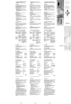
Servicing and
repair instructions
SOMNOsmart 2
smart PAP-device WM 24900
SOMNOsmart 2 with SOMNOclick WM 24950
SOMNOsmart 2 with SOMNOclick 300
WM 24975
SOMNOset
Titration Device WM 23200
SOMNOset with SOMNOsupport WM 23210
SOMNOsoft +
CPAP device with softPAP exhalation relief and
therapy monitoring WM 24600
SOMNOsoft + with SOMNOclick WM 24610
SOMNOsoft + with SOMNOclick 300 WM 24675
Contents
Introduction . . . . . . . . . . . . . . . . . . . . . . . . . 3
6. Troubleshooting . . . . . . . . . . . . . . . . . . . . . 20
1. Overview . . . . . . . . . . . . . . . . . . . . . . . . . . . 4
7. Repair Information and Instructions . . . . . . . 22
7.1 General . . . . . . . . . . . . . . . . . . . . . .22
7.2 Opening the device . . . . . . . . . . . . . .23
7.3 Closing the device . . . . . . . . . . . . . . .24
7.4 Replace Displayboard . . . . . . . . . . . .25
7.5 Replacing the fascia film . . . . . . . . . . .26
7.6 Changing fuses on the Powerboard . . .26
7.7 Replacing the Powerboard . . . . . . . . .27
7.8 Replacing the Smartboard/Softboard . .30
7.9 Replacing battery on Smartboard or
Softboard. . . . . . . . . . . . . . . . . . . . .31
7.10 Replacing transformer . . . . . . . . . . . . .31
7.11 Replacing the oscillation generator
(SOMNOsmart 2 and SOMNOset only) .34
7.12 Replacing the microphone
(SOMNOsmart 2 and SOMNOset only) .35
7.13 Replacing Smartbox/Comfortbox . . . . .35
7.14 Replacing the fan. . . . . . . . . . . . . . . .36
7.15 Replacing lower part of housing . . . . . .41
7.16 Replacing upper part of housing . . . . . .42
2. Description . . . . . . . . . . . . . . . . . . . . . . . . . . 6
2.1 Purpose of SOMNOsmart 2 . . . . . . . . . 6
2.2 Purpose of SOMNOset . . . . . . . . . . . . 6
2.3 Uses SOMNOsoft + . . . . . . . . . . . . . . . 7
2.4 Function of SOMNOsmart 2 . . . . . . . . . 7
2.5 Function of SOMNOset . . . . . . . . . . . . 8
2.6 Functional description of SOMNOsoft + . . 9
3. Servicing . . . . . . . . . . . . . . . . . . . . . . . . . . 10
3.1 Intervals . . . . . . . . . . . . . . . . . . . . . . 10
3.2 Filter change . . . . . . . . . . . . . . . . . . . 10
– Coarse dust filter
– Fine filter
3.3 Cleaning the device . . . . . . . . . . . . . . 11
3.4 Resetting the service symbol . . . . . . . . . 12
3.5 Disposal . . . . . . . . . . . . . . . . . . . . . 12
4. Hygienic preparation . . . . . . . . . . . . . . . . . 13
4.1 Cleaning and disinfecting after use . . . . 13
4.2 Cleaning and disinfection after repair . . 13
4.3 Cleaning and disinfecting on change of
patient . . . . . . . . . . . . . . . . . . . . . . . 13
4.4 Cleaning and disinfecting the
SOMNOclick/SOMNOclick 300
after use. . . . . . . . . . . . . . . . . . . . . .14
4.5 Cleaning and disinfecting the
SOMNOclick/SOMNOclick 300 on
change of patient . . . . . . . . . . . . . . .14
5. Test the device . . . . . . . . . . . . . . . . . . . . . . 15
5.1 General . . . . . . . . . . . . . . . . . . . . . .15
5.2 Performing the check . . . . . . . . . . . . .15
– Checking the power cord
– Checking the housing
– Checking display
– Checking pressure and button functions
– Checking OP signal (SOMNOsmart 2
and SOMNOset)
– Checking function of humidifier
8. Tools, testing equipment and disinfectants . . 44
8.1 Tools . . . . . . . . . . . . . . . . . . . . . . . .44
8.2 Testing equipment and fixtures . . . . . . .44
8.3 Disinfectant. . . . . . . . . . . . . . . . . . . .45
9. Spare parts . . . . . . . . . . . . . . . . . . . . . . . . 46
9.1 Spare parts list . . . . . . . . . . . . . . . . .46
9.2 Spare parts required for servicing . . . . .48
10. Technical data . . . . . . . . . . . . . . . . . . . . . . 50
10.1 Specifications . . . . . . . . . . . . . . . . .50
10.2 Pressure-Volume curve. . . . . . . . . . . . .51
10.3 Safety distances . . . . . . . . . . . . . . . .52
11. Repair and service record . . . . . . . . . . . . . . 53
© Copyright Weinmann GmbH & Co. KG.
The content and presentation are copyright protected and may only be used by authorised Weinmann Service Partners in the
course of their service operations. The content must not be reproduced or passed on to third parties. The complete documents
must be returned on termination of the cooperation with Weinmann.
2
Introduction
For decades Weinmann has been developing,
manufacturing and marketing devices for sleep
apnoea therapy, inhalation therapy, oxygen
therapy and emergency medical care.
With its SOMNOcomfort and SOMNOvent S
and ST, and also SOMNOsmart 2, SOMNOset
and SOMNOsoft +, Weinmann offers a
graduated therapy concept from treatment of
sleep-related respiratory disorders to treatment of
global respiratory insufficiency.
The aim of these service and repair instructions is
to familiarize you, as a trained expert in the field,
with the function, technology, servicing and repair
of the SOMNOsmart 2, SOMNOset and
SOMNOsoft +. This will enable you to give your
customers proper instructions, eliminate faults
yourself, perform the tests specified in the operating
instructions, carry out any repairs and service the
device in accordance with these service and
repair instructions.
In the event of a guarantee claim, the devices must be
sent to Weinmann.
To enable us to process ex gratia requests or
warranty claims, please enclose the customer’s
proof of purchase (invoice) with the device.
Repairs or servicing work may be performed only
by Weinmann or by trained specialist staff.
You are responsible for repairs carried out yourself
and for their warranty!
Use only original Weinmann spare parts for repairs.
Please bear in mind:
Your customer trusts you and relies on your expert
capability, just as you rely on Weinmann.
Note:
For the following information, please consult the Operating Instructions for the individual devices:
•
Safety instructions
•
Preparing for use
•
Operation
•
Cleaning and disinfecting after use
•
Guarantee
Introduction
3
1. Overview
SOMNOsmart 2, SOMNOset and SOMNOsoft +
9 Drying adapter
15 Cap
2 Bacteria filter
3 Power cord
14 Mask
8 Stopper (2x)
13 Exhalation system
1 Therapy device
7 Device outlet port
10 Adapter
12 Hose system
11 Pressure measurement tube
6 Humidifier connection
5 Control panel
and display
4 Ports
Control panel and display SOMNOsmart 2
17 Total therapy time /
Daily therapy time
16 Softstart symbol
22 Humidifier
activated
23 Service symbol
18 Change filters
19 Pressure rise/Pressure
drop and softPAP mode
28 Humidifier
activated
indicator
20 Therapy pressure
lamp
21 LC display
24 On/Off button
26 Softstart button
27 Humidifier button
(Levels 1-6)
Control panel and display SOMNOset
17 Total therapy time /
Daily therapy time
16 Softstart symbol
18 Change filters
Pini
Pini
24 On/Off
button
22 Humidifier
activated
23 Service symbol
25 Set button
19 Pressure rise/
Pressure drop
20 Therapy pressure
21 LC display
28 Humidifier
indicator lamp
26 Softstart button
27 Humidifier button
(Levels 1-6)
Control panel and display SOMNOsoft +
16 Softstart symbol
17 Total therapy time /
Daily therapy time
18 Change filters
SOMNOsoft +
1 hPa
22 Humidifier
activated
23 Service symbol
4
Overview
1 cmH2O
24 On/Off
button
19 softPAP mode
activated
20 Therapy pressure
21 LC display
27 Humidifier button 26 Softstart button
28 Humidifier
(Levels 1-6)
indicator lamp
Device combinations
29 Filter cover
IN
LER
WAND
DC-AC INVERTER
DC-AC
OUT
31 Rating plate
32 Carrying bag
33 Power inverter
34 O2 switching valve
35 SOMNOclick/
SOMNOclick 300
30 Power connection
Overview
5
2. Description
Note:
SOMNOsmart 2, SOMNOset and SOMNOsoft + are of largely identical basic design. They differ only in
the software, display and fascia film. SOMNOsoft + has no oscillation generator and no microphone.
2.1 Purpose of SOMNOsmart 2
SOMNOsmart 2 is a smartPAP device for treating
sleep-related respiratory disorders.
SOMNOsmart 2 from software version 6.0; in general from device no. 10,000: The softPAP mode in-
SOMNOsmart 2 generates positive airway
pressure (PAP).
creases patient comfort by means of a brief
pressure reduction during the transition from inhalation to exhalation.
SOMNOsmart 2 is a self-regulating device. It
recognizes respiratory events and varies the
airway pressure accordingly.
While the patient is asleep, the airways are
braced by the air pressure generated.
Airway pressure is administered by means of a
mask.
SOMNOsmart 2 can be used for people aged
12 years or more.
Important!
SOMNOsmart 2 can reliably prevent closure of
the airways only if the upper and lower pressure
limits specific to the patient and prescribed by a
doctor have been determined, e.g. in a sleep
laboratory, and set accordingly.
SOMNOsmart 2 is not suitable for use as a lifesupport system.
2.2 Purpose of SOMNOset
SOMNOset is a device for efficient adjustment to
CPAP patients. The device can work on a standalone basis or in conjunction with the remote
control SOMNOadjust or an extended user
interface of the SOMNOsupport software. The
recorded data can also be visualized and
evaluated with the aid of SOMNOsupport.
Airway pressure is administered by means of a
mask.
SOMNOset permits titration without the patient
coming to a sleep laboratory. Titration can be
carried out in the patient's familiar surroundings.
From the data recorded, the physician can
determine the required therapy pressure. This
pressure is set on the therapy device which is given
to the patient for long-term therapy following
titration.
SOMNOset generates positive airway pressure
(PAP).
SOMNOset may be operated as a self-regulating
device. In that case SOMNOset recognizes
respiratory events and varies the airway pressure
accordingly.
While the patient is asleep, the airways are
braced by the air pressure generated.
6
Description
In the Autotitration mode the device determines,
during the titration night, a therapy pressure
(recommended titration pressure) that largely
prevents closure of the upper airways.
SOMNOset can be used for people aged 12
years or more.
Important!
SOMNOset is not suitable for use as a life-support
system.
2.3 Uses SOMNOsoft +
SOMNOsoft + is a CPAP device for treating sleeprelated respiratory disorders.
Airway pressure is administered by means of a
mask.
SOMNOsoft + generates positive airway pressure
(PAP).
SOMNOsoft + can be used both in CPAP mode
and in softPAP mode for individuals aged 12 years
or more.
The softPAP mode increases patient comfort by
means of a brief pressure reduction during the transition from inhalation to exhalation.
SOMNOsoft + recognises respiratory events. This
permits efficient therapy control.
During sleeping, the patient’s airways are braced
by the air pressure generated.
Important!
SOMNOsoft + can reliably prevent closure of the
airways only if the therapy pressure specific to the
patient and prescribed by a physician has been
determined, e.g. in a sleep laboratory.
SOMNOsoft + is not suitable for use as a life-support system.
2.4 Function of SOMNOsmart 2
SOMNOsmart 2 works on the principle of an
electrically powered flow generator delivering an
electronically controlled constant pressure level.
The exhalation system before the mask prevents
accumulation of CO2-enriched expired air in the
hose system.
A radial fan draws in ambient air through a filter
and conveys it to the device outlet port. From here
the air flows through the hose system and the mask
to the patient.
Auto switch-on can be activated on the
SOMNOsmart 2. The device can then be
switched on by breathing into the mask. If there is
no pressure for about 5 seconds (e.g. because the
mask is taken off), the SOMNOsmart 2 switches
off automatically.
An oscillation generator creates a slight sinusoidal
pneumatic oscillation in the air flow produced by
the device.
The airway and oscillation pressure is registered
via the pressure measurement tube in the mask.
The current oscillation pressure reading is
compared with an average value and the
preceding values. This evaluation of the oscillation
pressure makes it possible to identify any
significant change in airway resistance and hence
to increase or reduce the therapy pressure via the
flow generator.
The pressure present in the mask is shown in the LC
display. The microprocessor-controlled flow
generator regulates the pressure at the value
determined.
The device also records a respiratory flow signal
that can be output to a PSG system or read off with
the aid of SOMNOsupport. This makes it possible
to identify apnoea, hypopnoea and respiratory
flow limitations.
Following a power failure and resumption of the
power supply, the status of SOMNOsmart 2 is the
same as it was before the power failure. The
stored data remain preserved.
There are two functions designed to make it easier
to go to sleep: (soft-)start or start pressure function.
(Soft-)start function: When this is switched on, the
pressure is adjusted to the (soft-)start pressure set by
the physician. The pressure limits then gradually increase to the set values. The time taken for this increase is adjustable. This function is suitable for
patients who find the high pressure unpleasant
while they are awake.
Additional function from software version 6.0:
Start pressure function: The pressure remains at the
set value throughout the start period. At the end of
the start period, the pressure is reduced to the lower pressure limit. This function is suitable for
patients who find low pressure unpleasant while
they are awake, or who need high pressure quickly after they have gone to sleep.
Description
7
In softPAP mode the respiratory flow curve is analysed continuously to ensure timely recognition of
the transition between inhalation and exhalation.
Before the transition to exhalation the therapy pressure is reduced to make it easier to breathe out.
The size of this pressure reduction can be set in two
stages: “slight” (stage 1) and “normal” (stage 2).
This increases patient comfort. Before the next inhalation phase, the pressure is raised to the therapy figure once again.
If apnoea or valid flow limitations occur while the
patient is sleeping, the softPAP mode is automatically deactivated for the relevant period. If the respiratory frequency is too high, the softPAP mode is
also temporarily deactivated. However, the therapy pressure remains reduced during this period.
In full face mode the device supports therapy with
a full face mask. The event-related pressure adjustment is modified accordingly.
2.5 Function of SOMNOset
SOMNOset works on the principle of an
electrically powered flow generator delivering an
electronically controlled constant pressure level.
the aid of SOMNOsupport. This makes it possible
to identify apnoea, hypopnoea and respiratory
flow limitations.
A radial fan draws in ambient air through a filter
and conveys it to the device outlet port. From here
the air flows through the hose system and the mask
to the patient.
The exhalation system before the mask prevents
accumulation of CO2-enriched expired air in the
hose system.
An oscillation generator creates a slight sinusoidal
pneumatic oscillation in the air flow produced by
the device.
The airway and oscillation pressure is registered
via the pressure measurement tube in the hose
system.
The current oscillation pressure reading is
compared with an average value and the
preceding values. This evaluation of the oscillation
pressure makes it possible to identify any
significant change in airway resistance and hence
to increase or reduce the therapy pressure via the
flow generator.
The pressure present in the mask is shown in the LC
display. The microprocessor-controlled flow
generator regulates the pressure at the value
determined.
The values determined are recorded. In
Autotitration mode, the recommended therapy
pressure is calculated at the end of the titration
night.
The device also records a respiratory flow signal
that can be output to a PSG system or read off with
8
Description
To make it easier for the patient to go to sleep, an
automatic Softstart system is incorporated for the
APAP and CPAP modes. When this is switched on,
the pressure is reduced to the Softstart pressure set
by the physician. The therapy pressure then
gradually increases to the set value. The period for
the pressure rise can be set in 5-minute steps
between 0 and 30 minutes. The automatic
Softstart system can be locked out by the
physician.
Auto switch-on can be activated in APAP and
CPAP modes. The device can then be switched on
by breathing into the mask. If there is no pressure
for about 5 seconds (e.g. because the mask is
taken off), the SOMNOset switches off
automatically.
If the power supply is interrupted and then
restored, data recording starts afresh in all modes.
In that case, pressure adjustment and event
evaluation restart in the Autotitration and APAP
modes. In the Pressure Profile and CPAP modes,
titration or therapy are continued in the status that
was active before the interruption. The stored data
remain recorded despite the interruption.
2.6 Functional description of SOMNOsoft +
SOMNOsoft + works on the principle of an electrically powered flow generator delivering an electronically controlled constant pressure level.
A radial fan draws in ambient air through a filter
and conveys it to the device outlet port. From here
the air flows through the hose system and mask to
the patient.
The airway pressure is registered via the pressure
measurement tube in the mask.
The pressure present in the mask is shown in the LC
display. The microprocessor-controlled flow generator regulates the pressure at the set value.
In softPAP mode the respiratory flow curve is analysed continuously to ensure timely recognition of
the transition between inhalation and exhalation.
Before the transition to exhalation the therapy pressure is reduced to make it easier to breathe out.
The size of this pressure reduction can be set in two
stages: “slight” (stage 1) and “normal” (stage 2).
This increases patient comfort. Before the next inhalation phase, the pressure is raised to the therapy figure once again.
If apnoea or valid flow limitations occur while the
patient is sleeping, the softPAP mode is automatically deactivated for the relevant period. If the respiratory frequency is too high, the softPAP mode is
also temporarily deactivated. However, the therapy pressure remains reduced during this period.
The device also records a respiratory flow signal
that can be output to a PSG system or read off with
the aid of SOMNOsupport. SOMNOsoft + recognises apnoea, hypopnoea and respiratory flow
limitations. This permits efficient therapy control.
The exhalation system in front of the mask prevents
accumulation of CO2-enriched expired air in the
tube system.
An automatic Softstart system is provided to enable
the patient to go to sleep more easily. When this
is switched on, the pressure is reduced to the Softstart pressure set by the physician. The therapy
pressure then gradually increases to the set value.
The period for the pressure rise can be set in 5minute steps between 0 and 30 minutes. The automatic Softstart system can be locked out by the
physician.
Auto switch-on can be activated on the
SOMNOsoft + The device can then be switched
on by breathing into the mask. If there is no pressure for about 5 seconds (e.g. because the mask
is taken off), SOMNOsoft + switches off automatically.
Following a power failure and resumption of the
power supply, the status of SOMNOsoft + is the
same as it was before the power failure. The
stored data remain preserved.
Description
9
3. Servicing
3.1 Intervals
The two filters 45 and 46 need to be checked regularly for soiling.
•
Coarse dust filter 45 must be changed every 6
months.
•
Fine filter 46 must be changed at least every
250 operating hours.
•
The pressure measurement tube 11 must be
changed at least every 6 months – and more
frequently if soiling is heavy.
For hygiene reasons we recommend:
•
replacing the complete mask system every 6 to
12 months depending on soiling, and
•
replacing the expiration system in accordance
with the relevant operating instructions.
See the section on “Cleaning” in the relevant
operating instructions.
The following preventive maintenance measures must also be carried out:
1. Service after every 5000 operating hours
(service symbol 23 appears in display and
must be reset after every service).
2. Service after a maximum of 2 years (see
service label on back of device).
3. The parts exposed to the air flow must be
cleaned every 10,000 hours or 4 years.
4. Every 2 years the battery on the Smartboard or
Softboard must be replaced.
After every service, replace the service label 87
with one bearing the new data (see “9. Spare
parts” on page 46). Use a hole punch or nail
scissors (V-shaped notch) to mark the month. Affix
the new service label to the left of the filter cover.
87
3.2 Filter change
3.2.1 Coarse dust filter
1. To ensure that no water runs into the device 1
when changing the filters, disconnect the
humidifier 35 from the device. Also observe
the operating instructions supplied.
2. Slightly raise the rear of the device or push the
back of the device off the edge of the table a
little, so that you can reach under the filter
cover 29.
10
Servicing
3. Press with your thumb on the underside of the
filter cover 29 and lift the cover off.
4. Pull out the coarse dust filter 45 with your
finger.
5. You can wash a soiled coarse dust filter in
clean water and reuse it after drying
thoroughly.
29
6. Insert the clean coarse dust filter 45.
7. Insert the filter cover 29 in the opening in the
housing with its upper edge first.
8. Using a finger to press in the catch on the
underside of the cover, fit the cover so that it
clicks into place.
9. If appropriate, fit the humidifier. Observe the
section “3.4 Humidifier” in the operating
instructions.
45
3.2.2 Fine filter
1. Remove the coarse dust filter 45 as described
under “3.2.1 Coarse dust filter”.
2. Remove the fine filter 46.
The fine filter must be changed if it has turned dark
grey, and in any case after 250 operating hours.
In the latter case the filter change symbol
appears.
3. Insert the new filter and filter cover 29 in
reverse order.
4. To clear the filter change symbol, hold down
the on/off button 24 when switching on the
device until the symbol disappears from the
display.
46
45
If the fine filter is changed because of soiling
before 250 operating hours are reached, the hour
counter must be reset to zero:
5. To do so, hold down the On/Off button 24
when switching on the device. After about 3
seconds the filter change symbol lights up and
after another 3 seconds it disappears. Now
you can release the button.
3.3 Cleaning the device
The parts exposed to the air flow must be cleaned
and disinfected every 10,000 hours or every 4
years. This must be done as described in Chapter
“4.3 Cleaning and disinfecting on change of
patient” on page 13.
After every service a test must be performed in
accordance with Chapter “5. Test the device” on
page 15.
Servicing
11
3.4 Resetting the service symbol
After every service/repair the service hours counter must be reset to “0”, and the service symbol 23 in the
display must be cleared. A new service label (current year + 2 years) must also be affixed to the back of the
device.
1. To reset the service hours counter to “0” or to
switch off the service symbol, hold down the
Softstart button 26 with the device switched off
until A0/A1 or soft0/soft1/soft2
appears in the display.
24
23
2. Now press the On/Off button 24 as well until
an S (for “service key”) appears.
26
3. Now release both buttons.
4. Briefly pressing the On/Off button 24 clears
the service key. If you want set the service
symbol again, press the On/Off button 24
again.
Pini
23
26
25
24
SOMNOsoft +
23
1 hPa
1 cmH2O
26
3.5 Disposal
Do not dispose of the device with
domestic waste. To dispose of the device
properly, please contact a licensed,
certified electronic scrap disposal
merchant. This address is available from
your Environment Officer or from your
local authority.
12
Servicing
24
4. Hygienic preparation
4.1 Cleaning and disinfecting after use
Caution!
This point is described in Chapter 5 “Cleaning and Disinfection” of the SOMNOsmart 2, SOMNOset or
SOMNOsoft + operating instructions.
Hygienic preparation of the device after repairs and for a new patient is described below.
4.2 Cleaning and disinfection after repair
In the event of repairs the following work should be performed by the qualified dealer.
Caution!
Be sure to follow the disinfectant manufacturer’s
instructions (8.3, page 45). You are
recommended to wear suitable gloves (e.g.
household or disposable gloves) during
disinfection procedures.
•
Wipe outside of device and power cord with
TERRALIN disinfectant.
•
Clean hoses, cap and mask as described in the
operating instructions or replace with new parts
(depending on condition).
•
Open device as described in 7.2.
•
Replace the coarse dust filter and fine filter 45
+ 46 as described in Chapter 3.2.
•
Clean the inside of the device and filter
housing with a vacuum cleaner. Thoroughly
clean any specially dirty parts.
•
Close device as described in 7.3.
4.3 Cleaning and disinfecting on change of patient
When making the device hygienic for a new patient, the following steps must be carried out:
Caution!
Be sure to follow the disinfectant manufacturer’s
instructions (8.3, page 45). You are
recommended to wear suitable gloves (e.g.
household or disposable gloves) during
disinfection procedures.
•
•
Replace the coarse dust filter and fine filter 45
+ 46 as described in Chapter 3.2.
•
Spray-disinfect device outlet 7, filter holder 44
and filter cover 29 twice with “MIKROZID
LIQUID”, taking care to wait for the prescribed
disinfection time in each case. At the
beginning of the disinfection time, also wipe
the accessible surfaces with a cloth moistened
with “MICROZID LIQUID”.
Wipe outside of device and power cord with
TERRALIN disinfectant. Dispose of hose and
mask system and carrying bag, and replace
with new parts.
•
Open device as described in Chapter 7.2.
•
Clean the inside of the device and filter
housing with a vacuum cleaner. Thoroughly
clean any specially dirty parts.
Caution!
No disinfectant residues must be left in the
pressure measurement stub of the device outlet
port 7; if necessary the pressure measurement
stub must be blown dry.
•
Replace OPS delivery tube 61 (only
SOMNOsmart 2 and SOMNOset).
Hygienic preparation
13
•
Open box 62/63 as described in Chapter
7.14.
•
Close box 62/63 again as described in
Chapter 7.14.
•
Replace both labyrinths 64 and 66, motor
frame 65, box damper insert 69 and cover
damper insert 68. Remove fan cap from fan.
•
Alternatively, box 62/63 can be replaced by
an exchange box (see “7.13 Replacing
Smartbox/Comfortbox” on page 35).
•
Spray-disinfect the box, fan and fan cap twice
with “MIKROZID LIQUID”, taking care to wait
for the prescribed disinfection time in each
case. At the beginning of the disinfection time,
also wipe the accessible surfaces with a cloth
moistened with “MICROZID LIQUID”.
•
Close appliance as described in Chapter 7.3.
Wipe housing and power cord with TERRALIN
disinfectant.
•
Set service symbol and clear it again, to reset
the service hours counter to “0” (see “3.4
Resetting the service symbol” on page 12).
Spray-disinfect fan blade twice with
“MIKROZID LIQUID”. The fan blades must not
be exposed to any mechanical forces.
•
Test the device.
•
Use SOMNOsupport to clear the patient data
stored in the device. Observe the relevant
operating instructions.
•
•
Dip-disinfect connecting tube 59 mit
“GIGASEPT FF”.
4.4 Cleaning and disinfecting the SOMNOclick/SOMNOclick 300
after use
This point is described in Chapter 4 “Cleaning and Disinfection” of the SOMNOclick or SOMNOclick 300
operating instructions.
4.5 Cleaning and disinfecting the SOMNOclick/SOMNOclick 300
on change of patient
When making the device hygienic for a new patient, the following steps must be carried out:
•
14
For hygiene reasons we recommend replacing
the plastic parts after a maximum of 2 years’
use. The spare parts list can be found in the
SOMNOclick/SOMNOclick 300 operating
instructions (WM 16719).
Hygienic preparation
•
If plastic parts and heating element are badly
soiled or covered with lime scale, offer the
customer a new device, otherwise:
Proceed as described in Chapter “4. Hygienic
preparation” of the SOMNOclick/
SOMNOclick 300 operating instructions
(WM 16719).
5. Test the device
5.1 General
Important
A test is required after every service or repair.
Please enter the following figures in your service
record sheet (see Page 53):
For SOMNOsmart 2: operating hours, humidifier
level, Softstart time and Softstart initial pressure,
and the patient’s pressure limits and pressure rise
rate as shown in the patient pass.
If the test reveals faults or deviations from the
specified values, the device must not be used
again until the faults are rectified.
To find out what may be causing the faults and
how to remedy the malfunction, see Chapter „6.
Troubleshooting“ on page 20.
For SOMNOset: operating hours, humidifier level,
Softstart time and Softstart initial pressure, and the
patient’s pressure limits and pressure rise rate as
shown in the patient pass, and also the mode.
For SOMNOsoft +: operating hours, humidifier
level, Softstart time and Softstart initial pressure,
CPAP pressure and mode.
5.2 Performing the check
5.2.1 Checking the power cord
1. Check the power cord 3.
Make sure that
– the insulation is sound,
– the cable is undamaged,
– there are no loose connections.
2. If necessary, change the power cord 3.
5.2.2 Checking the housing
Check the general condition of the housing.
– If the housing is damaged or faulty, replace
the relevant side of the device (see „7.15
Replacing lower part of housing“ on
page 41 or „7.16 Replacing upper part of
housing“ on page 42).
Test the device
15
5.2.3 Checking display
1. Check that the fascia film of the control panel
5 is flat all over and firmly in place. If it is not,
replace the fascia film (see “7.5 Replacing the
fascia film” on page 26).
2. Now fix up the power supply by connecting
one end of the power cord 3 to the device and
the other to the wall socket.
3. Press the On/Off button 24. The LC display 21
appears.
4. Briefly open and close the device outlet port.
The LC display changes.
5
21
26
24
5. Switch off the device with button 24. The day’s
therapy duration appears briefly in the LC
display 21. Then only “0” is left showing on the
LC display 21.
5.2.4 Checking pressure and button functions
1. Assemble the device ready for use with hose
system 12, mask 14 and power cord 3
attached.
Note:
If the SOMNOset is in Autotitration or Pressure
Profile mode, switch to APAP or CPAP.
2. With the device switched off, press the
Softstart button 26 repeatedly until the current
auto switch-on setting (A0 or A1) appears in the
display.
Note:
24
21
if the exhalation relief setting (soft0/soft1/
soft2) appears in the display, first press the
humidifier button 27 to switch to the auto
switch-on setting.
26
27
3. If necessary, press the On/Off button 24 to
change the setting to A1.
– The device will now be switched on
automatically as soon as breathing through
the mask starts (pressure > 0.5 hPa),
– When the mask is removed, the device must
switch off after 5 seconds.
Pini
21
27
4. The day’s therapy duration appears briefly in
the LC display 21. After that, only “0” is left
showing on the LC display 21.
16
Test the device
25
1 hPa
21
27
24
24
SOMNOsoft +
5. Press the On/Off button 24 to switch the
device on. For 3 seconds the display shows
the total use time 17.
6. Close the opening of the mask, e.g. with your
thumb or hand, and hold it closed.
26
1 cmH2O
26
7. If Softstart is switched on, switch it off by
pressing button 26. The radial fan delivers air
through the hose system to the mask, and the
current pressure in hPa is shown in the LC
display 21.
8. Compare the pressure shown in the LC
display 21 with the prescribed minimum
pressure limit. After approx. 1 minute the
difference must be not more than ± 0.2 hPa.
9. Use a pressure gauge to check the set pressure
at the connection stub of the mask.
– To do so, remove one stopper.
Stopper
– Connect a pressure gauge to the open
connection stub.
Compare the reading with the figure shown on
the LC display 21. After approx. 1 minute the
difference must be not more than ± 0.4 hPa.
10. Press button 26 to switch on Softstart. The
Softstart symbol 16 appears and the LC
display 21 shows the Softstart time. At the
same time the pressure is reduced to the initial
Softstart pressure.
24
16
21
26
The Softstart function can be locked out by the
physician. In that case the Softstart initial
pressure shown in the display is “– –”.
16
Pini
21
16
26
24
24
SOMNOsoft +
1 hPa
21
1 cmH2O
26
Test the device
17
5.2.5 Checking OP signal (SOMNOsmart 2 and SOMNOset)
Measuring equipment required:
•
ESD workplace,
•
Multimeter,
•
PSG connecting cable, WM 23976,
•
Operating instructions for PSG connecting cable, WM 16250.
Important
Auto switch-on must be deactivated.
1. Use SOMNOsupport to assign the OP signal
to channel 1.
2. Insert the Western plug W of the PSG
connecting cable in port 4 of the device.
3. Connect the pair of wires marked O to the
multimeter. The insulated wire 6 is the plus pole
for the oscilatory pressure (OP), the bare wires
5 are the earth.
4. Select a suitable measuring range on the
multimeter, e.g. 0 – 2 V DC.
5. Switch on the device at the On/Off switch 24.
6. With the mask open, the voltage measured
must be ≤ 0.3 V DC.
With the mask closed (use your hand to hold
it closed), the voltage measured must be
≥ 0.4 V DC.
If no OP signal can be measured, remove the
battery from the device (see “7.9 Replacing
battery on Smartboard or Softboard” on
page 31) for a few minutes, then put it back.
Perform the measurement again. If there is still
no measurable OPS, the Smartboard must be
replaced.
7. Switch off the device at the On/Off switch 24.
18
Test the device
5 1 5
W
T
6
O
5.2.6 Checking function of humidifier
1. Make a visual inspection of the plastic
housing:
If there are any cracks/damage or heavy
soiling, the plastic parts or seals must be
replaced.
2. Fill the humidifier up to the mark with water.
3. Check that the humidifier is not leaking.
4. Pour the water out.
5. Now pour in 50 ml water.
6. Click-fit the humidifier to the therapy device.
7. Insert the red drying adapter (supplied with the
therapy unit) in the outlet connection stub of the
humidifier.
8. Push the hose system onto the drying adapter.
9. Switch on the therapy appliance.
10. Switch on the humidifier by pressing the
Humidifier button
on the therapy device.
11. Select heating level 6 on the therapy device.
12. Check that the humidifier is heating up.
13. Remove the hose system by pressing the
adapter release catch.
14. Remove the red drying adapter from the
humidifier by twisting it slightly.
If servicing was completed successfully, reset the
service symbol (see “3.4 Resetting the service
symbol” on page 12).
Test the device
19
6. Troubleshooting
Fault
Cause
No running noise,
”Standby” and
”Operating” indicators
do not come on.
No power supply.
Check connection between power cord and device or socket.
Check power supply with a different device (e.g. lamp). If
necessary, replace power cord.
Fuse has blown.
Replace fuse (Chapter 7.6, page 26).
Transformer defective.
Replace transformer (Chapter 7.10, page 31).
Display board defective
Replace displayboard (Chapter 7.4, page 25).
Smartboard or Softboard
Replace Smartboard or Softboard (Chapter 7.8, page 30).
faulty.
Powerboard defective.
No running noise after
”Operating” indicator
comes on.
Rectifying faults
Motor not turning.
Replace Powerboard (Chapter 7.7, page 27). Send defective
Powerboard to manufacturer for fault analysis.
Replace Powerboard (Chapter 7.7, page 27). Send defective
Powerboard to manufacturer for fault analysis.
Replace fan (Chapter 7.14, page 36).
Transformer defective.
Replace transformer (Chapter 7.10, page 31).
Fuse has blown.
Replace fuse (Chapter 7.6, page 26).
Faulty display or none at
Display defective.
all.
Replace displayboard (Chapter 7.4, page 25).
Tolerance of therapy
Smartboard or Softboard
pressure is >0.4 hPa after
Replace Smartboard or Softboard (Chapter 7.8, page 30).
faulty.
1 minute.
Device cannot be
switched on by breathing
into mask in Automatic
mode.
Automatic mode not
active.
Activate auto switch-on
(see 4.1. of operating instructions).
SOMNOset only:
Autotitration or Pressure
Profile mode active.
Auto switch-on is not available in these modes. (See
“Supplementary Operating Instructions for Medical Staff
SOMNOset”).
Powerboard defective
Replace Powerboard (Chapter 7.7, page 27).
Smartboard or Softboard
Replace Smartboard or Softboard (Chapter 7.8, page 30).
faulty.
Device runs, but does not Filters soiled.
reach lower pressure
Leak in mask.
limit.
Auto switch-on mode not
Device does not switch activated
off 5 seconds after mask SOMNOset only:
is removed.
Autotitration or Pressure
Profile mode active.
Filter change indicator
comes on.
Service symbol
on
comes
Filters soiled.
Change both filters (Chapter 3.2, page 10).
Adjust cap and/or headstraps so that mask is a firm fit.
Activate auto switch-on (see section 4.1 of operating instructions).
Auto switch-on is not available in these modes. (See
“Supplementary Operating Instructions for Medical Staff
SOMNOset”).
Clean or change both filters (Chapter 3.2, page 10).
Have device serviced as soon as possible by Weinmann or an
authorized dealer.
Battery on Smartboard/
Softboard run down,
Replace battery on Smartboard/Softboard (Chapter 7.9,
Internal
clock
data
not
page 31) and reset date/time.
Error message “Err b” in
plausible
display
Internal clock data not
Replace Smartboard/Softboard (Chapter 7.8, page 30) and
plausible
reset date/time.
20
Troubleshooting
Data stored in E2Prom
incorrect (e.g.
Error message “Err d” in
Replace Smartboard or Softboard (Chapter 7.8, page 30) and
compliance counter,
display
reset date/time.
operating hours counter),
therapy data are correct
Check microphone, replace if necessary.
Error message “Err P” in
display
Oscillation pump
defective
Replace oscillation pump.
Replace Smartboard or Softboard (Chapter 7.8, page 30).
Error message “Err c” in
display
Pressure sensor not
calibrated or incorrectly
calibrated
Replace Smartboard or Softboard (Chapter 7.8, page 30).
Check fuses and replace if necessary (Chapter 7.6, page 26).
Replace Powerboard (Chapter 7.7, page 27).
Error message “Err S” in
Fan not running
display
Replace Smartboard or Softboard (Chapter 7.8, page 30).
Replace fan (Chapter 7.14, page 36).
Check continuity of pressure measurement zone.
Therapy data stored in
Error message “Err E” in E2Prom (e.g. pressures,
display
pressure calibration) are
incorrect
Water in humidifier does
not heat up.
Replace Smartboard or Softboard (Chapter 7.8, page 30) and
reset date/time.
Humidifier defective.
Test with different humidifier. If device defective, send humidifier
to manufacturer.
Powerboard defective.
Replace Powerboard (Chapter 7.7, page 27). Send defective
Powerboard to manufacturer for fault analysis.
Power cord damaged
Replace power cord.
Ribbon cable for
membrane keyboard has Check whether ribbon cable is correctly connected to
Device will not switch on slipped out of
Displayboard.
via membrane keyboard connection.
Fascia film defective
Replace fascia film (Chapter 7.5, page 26).
Troubleshooting
21
7. Repair Information and Instructions
7.1 General
Always perform repairs to SOMNOsmart 2, SOMNOset and SOMNOsoft + at an ESD workplace.
•
Observe the safety information in the operating
instructions for SOMNOsmart 2, SOMNOset and
SOMNOsoft +.
•
All operations on this device require detailed
knowledge and observation of the Operating
Instructions and the Service and Repair
Instructions.
•
Do not carry out any repairs that are not
described in these Service and Repair
Instructions. This is the only way to guarantee
trouble-free functioning of SOMNOsmart 2,
SOMNOset and SOMNOsoft +.
•
Make sure that your hands and workplace are
clean during the repair work.
•
Be sure to carry out a test after every repair
(see “5. Test the device” on page 15).
•
If you replace components or individual parts,
use only genuine Weinmann parts.
•
When ordering the lower part of the
housing 42, please specify device type, year
of manufacture and device number.
Note:
The item numbers quoted in the following text are identical to the item numbers in the spare parts list on
Page 46 and the overview on Page 4.
Important!
These service and repair instructions are for the devices
SOMNOsmart 2, SOMNOset and SOMNOsoft +.
In most cases the description is the same for all three devices. If this is not the case, the text draws attention to
the fact. The illustrations usually show the maximum
equipment level, with oscillation generator, microphone
and the relevant cables. Please note that SOMNOsoft +
does not have these components.
Oscillation generator
SOMNOsmart 2, SOMNOset
SOMNOsoft +
22
Repair Information and Instructions
7.2 Opening the device
Tools and equipment required:
•
Allen key 3 mm,
•
ESD workplace.
Caution!
Always pull out the mains plug before opening the device.
1. Place the device upside down on a non-slip
surface.
2. Slacken and remove the 2 screws 40 and the 2
screws 41.
3. Hinge the lower part of the housing 42 away
to the side.
40
42
41
48
4. Pull the Western port of the connecting cable
48 out of the housing base 42.
5. Disconnect plug X300 from the board.
6. Now you can put the lower part of the
housing 42 on one side.
X300
Caution!
On older devices there is a second connecting
cable:
SOMNOsmart 2 up to device number 7256
SOMNOset up to device number 1112
SOMNOsoft + up to device number 1264
Second connecting cable
7. Remove the Western socket from the base of the
device.
Repair Information and Instructions
23
If the second connecting cable is damaged,
proceed as follows:
1. Replace the connecting cable with connecting
cable 49.
Smartboard or Softboard
Plug for
Smartboard or
Softboard
2. Replace the base of the device (see “7.15 Replacing lower part of housing” on page 41).
49
Plug for Powerboard (X1)
red
7.3 Closing the device
Tools and equipment required:
•
Allen key 3 mm,
•
ESD workplace.
1. Hold the lower part of the housing 42 against
the upper part 43.
2. Push connector X300 onto the Powerboard 47.
The lug on the connector must be facing the
catch.
3. Push the Western port of the connecting cable
48 into the guides in the lower part of the
housing 42.
48
42
51/52/53
47
4. Check that all tubes and cables are firmly
connected. If necessary, push them carefully
right onto the stubs (tubes) or auf die connection
points (cables).
5. Align the Powerboard 47 and Smartboard 51/
52 or Softboard 53 in the guides inside the
device.
6. Place the lower part of the housing 42 on the
upper part 43.
Make sure that the Powerboard 47 is correctly
fitted and that the connecting cable 48 is not
trapped.
7. Now screw the upper part of the housing tight
using the 2 screws 40 and 2 screws 41.
8. Finally, turn the device the right way up.
24
Repair Information and Instructions
X300
43
40
41
7.4 Replace Displayboard
Tools and equipment required:
•
Allen key 3 mm,
•
ESD workplace,
•
Phillips screwdriver size 1.
1. Open the device (see “7.2 Opening the
device” on page 23).
2. Pull the connecting cable off the Smartboard/
Softboard.
3. Detach the ribbon cable for the fascia film:
To do so, pull the catch upwards. Then you can
lift out the ribbon cable.
Connecting cable
Caution:
Ribbon cable
If the catch is not opened correctly, the ribbon
cable will be damaged when pulling it out.
Catch
4. Slacken the two screws 55 slightly.
55
50
56
5. Remove the Displayboard 50 by pushing it
upwards against the clamp plates 56,
removing it at the bottom from the holder in the
housing, and then lifting it out.
6. Insert a new Displayboard 50:
First push the Displayboard under the clamp
plates 56, then place it in the holder in the
housing.
7. Align the clamp plates 56 and screw them tight
with screws 55.
8. Reconnect the ribbon cable for the fascia film
to the Displayboard.
– Pull the catch upwards.
– Push the ribbon cable into the connection.
– Press the catch down again.
9. Push the connecting cable for the
Displayboard onto the appropriate connector
on the Smartboard/Softboard.
Ribbon cable
Connecting
cable
Catch
10. Close the device (see “7.3 Closing the
device” on page 24).
11. Perform a test (see “5. Test the device” on
page 15).
Repair Information and Instructions
25
7.5 Replacing the fascia film
Tools and equipment required:
•
Allen key 3 mm,
•
ESD workplace,
•
Phillips screwdriver size 1,
•
Knife with smooth, flat blade.
1. Open the device (see “7.2 Opening the
device” on page 23).
2. Remove the Displayboard (see “7.4 Replace
Displayboard” on page 25, steps 3. to 5.).
3. Detach fascia film with a knife blade and pull
off carefully.
Degrease this area of the housing with a little
70%-strength isopropanol.
4. Remove the protective film from the inside of the
new fascia film and stick the fascia film 37/
38/39 to the appropriate part of the housing.
Take care when inserting the ribbon cable
through the opening in the housing; it must be
properly routed without any kinks.
5. Using your finger nail, carefully remove the
outer protective flim from the new fascia film.
6. Fit the Displayboard (see “7.4 Replace
Displayboard”, steps 6. to 8.).
7. Close the device (see “7.3 Closing the
device” on page 24).
8. Perform a test (see “5. Test the device” on
page 15).
7.6 Changing fuses on the Powerboard
Tools and equipment required:
•
Allen key 3 mm,
•
ESD workplace.
1. Open the device (see “7.2 Opening the
device” on page 23).
2. Carefully lift the Powerboard 47 and
Smartboard 51/52 or Softboard 53 slightly.
26
Repair Information and Instructions
Ribbon cable
3. Check whether one of the fuses F1 (88),
F2 (89), F3 (89) or F4 (89) has blown.
F3 (89)
F4 (89)
V IO
SW
GR
BLGE
Caution:
Fuses 88 (F1) and 89 (F2, F3, F4) have
RT
4. Remove the faulty fuse and replace it with a
new one. Fuses F3 (89) and F4 (89) must
always be changed at the same time.
GN WS
F2 (89)
different current ratings! Take care to use the
right rating.
F1 (88)
5. Carefully press Powerboard 47 and
Smartboard 51/52 or Softboard 53 back into
the groove in the housing.
6. Close the device (see “7.3 Closing the
device” on page 24).
7. Perform a test (see “5. Test the device” on
page 15).
7.7 Replacing the Powerboard
Tools and equipment required:
•
Allen key 3 mm
•
Philips screwdriver
•
ESD workplace.
1. Open the device (see “7.2 Opening the
device” on page 23).
51/52/53
47
X4
X5
2. Pull the display plug off the Smartboard/
Softboard.
Display
connector
3. Does not apply to SOMNOsoft +:
Detach plugs X5 and X4 from Smartboard 51/
52.
4. Detach the pressure measurement tube 60 from
the stub at the device outlet port.
60
5. Carefully lift Powerboard 47 and Smartboard
51/52 or Softboard 53 from inside the device.
6. Press the catch and remove the connector of
the connecting cable 48 from the Powerboard.
48
49
Guide hole
47
7. Pull plugs X6, X5 and X4 off the power board
47.
RT
VIO
SW
8. Carefully pull the three cables out through the
guide hole in the Powerboard.
GR
GN WS
BL GE
Catch
X4 X5 X6
Repair Information and Instructions
27
9. Undo the connector catch and carefully pull
out plug X100.
GR
GN WS
BL GE
12. Undo the other 3 screws 55.
VIO
SW
X100
11. Loosen the screws 55 on the battery holder
and remove the spring 57 and the sealing
washer 58 from the Smartboard.
RT
10. Remove the defective Powerboard 47 together
with Smartboard 51/52 or Softboard 53 from
the device.
Catch
55
58
57
55
13. Carefully detach Smartboard 51/52 or
Softboard 53 from the Powerboard.
51, 52
14. Disconnect plug X1 of the connecting cable 49
from the Powerboard. Smartboard/Softboard
and Powerboard are now completely
separated
X2
X1
54
Caution:
Make sure you do not confuse the two plugs
for the connecting cable 49.
Smartboard or Softboard
Plug for
Smartboard or
Softboard
15. Unscrew the distance pieces 54 from the defective
Powerboard.
16. Place plug X1 of the connecting cable 49 firmly on
the new Powerboard.
49
Plug for Powerboard (X1)
red
17. Carefully place Smartboard 51/52 or
Softboard 53 on the new Powerboard so that
plug X2 of the Powerboard fits into the
corresponding coupling on the Smartboard
(see double arrow in diagram).
18. Place the spring 57 and the sealing washer 58
on the battery holder on the Smartboard/
Softboard and fix the two parts with a screw
55.
19. Fasten the Smartboard 51/52 or Softboard 53
to the Powerboard with the remaining 3
screws 55.
20. Now insert the Powerboard 47 together with
the Smartboard/Softboard in the device as
described in the following steps.
28
Repair Information and Instructions
RT
21. Run the cable of plug X100 under the
Powerboard 47 and insert the plug in the
appropriate connection.
VIO
SW
GR
GN WS
BL GE
X100
22. Push plug of connecting cable 48 onto the
Powerboard.
48
47
Catch
Guide hole
23. Carefully thread the three cable harnesses for
X4, X5 and X6 into the guide hole of the
Powerboard.
RT
VIO
SW
24. Connect the transformer plugs X4, X5 and X6
to the Powerboard.
GR
GN WS
BL GE
Caution!
Do not under any circumstances confuse plugs X4
and X5. The plugs can be distinguished by the
colours of the wires:
Catch
X4: black and grey wires (“SW” + “GR”),
X5: violet and red wires (“VIO” + “RT”).
X4 X5 X6
The colours are likewise indicated as
abbreviations on the Powerboard.
25. Carefully insert the boards into the upper part
of the housing again. When doing so, run the
connecting cables 48 and 49 along under the
Smartboard/Softboard.
Caution!
Make sure that no cables are jammed between
the housing and the boards.
26. Fit the pressure measurement tube 60 onto the
stub at the device outlet port.
47
X4
X5
27. Connect the display connector to the
Smartboard/Softboard.
28. Does not apply to SOMNOsoft +:
Attach the plug of the microphone cable X5
(marked on the board as “MIC”) and the plug
of the oscillation generator cable X4 (marked
on the board as “OGEN”), and also the display
connector to the Smartboard.
Display
connector
60
29. Close the device (see “7.3 Closing the
device” on page 24).
30. Perform a test (see “5. Test the device” on
page 15).
Repair Information and Instructions
29
7.8 Replacing the Smartboard/Softboard
Tools and equipment required:
•
ESD workplace,
•
Allen key 3 mm,
•
Phillips screwdriver size 1.
1. Open the device (see “7.2 Opening the
device” on page 23).
2. Carefully remove the Powerboard 47 (see
“7.7 Replacing the Powerboard” on
page 27, steps 5. to 14.).
3. Disconnect the plug of the connecting cable
49 from the Powerboard. Smartboard/
Softboard and Powerboard are now
completely separated.
55
58
57
55
51, 52
Caution:
Make sure you do not confuse the two plugs
for the connecting cable 49.
X2
Plug for
Smartboard or
Softboard
5. Connect the plug of connecting cable 49
firmly to the new Smartboard/Softboard and
to the Powerboard.
7. Now fit the Powerboard 47 (see “7.7
Replacing the Powerboard”, steps 18. to 28.).
8. Close the device (see “7.3 Closing the
device” on page 24).
9. Reset the date and time and the therapy
parameters. To do so, either use
SOMNOadjust or proceed as described in
the setting instructions for SOMNOsmart 2/
SOMNOsoft + or the operating instructions for
medical staff for SOMNOset.
10. Perform a test (see “5. Test the device” on
page 15).
30
Repair Information and Instructions
54
Smartboard or Softboard
4. Place the defective Smartboard/Softboard on
one side.
6. Carefully place Smartboard 51/52 or
Softboard 53 on the new Powerboard so that
plug X2 of the Powerboard fits into the
corresponding coupling on the Smartboard/
Softboard (see double arrow in diagram).
X1
49
Plug for Powerboard (X1)
red
7.9 Replacing battery on Smartboard or Softboard
1. Open the device (see “7.2 Opening the
device” on page 23).
2. Loosen the screw 55 on the battery holder and
remove the spring 57 and the sealing washer
58 from the Smartboard/Softboard. Place the
parts on one side.
3. Remove the battery from its holder on the
Smartboard/Softboard.
57
55
58 Battery Support
4. Insert a new battery.
5. Place the spring 57 and the sealing washer 58
on the battery holder on the Smartboard/
Softboard and fix the two parts with screw 55.
6. Close the device (see “7.3 Closing the
device” on page 24).
7. Reset the date and time. To do so, either use
SOMNOadjust or proceed as described in
the setting instructions for SOMNOsmart 2/
SOMNOsoft + or the operating instructions for
medical staff for SOMNOset.
8. Perform a test (see “5. Test the device” on
page 15).
7.10 Replacing transformer
Tools and equipment required:
•
ESD workplace,
•
Allen key 3 mm,
•
Torque wrench,
•
Tubular hexagon box spanner 8 mm,
•
Cable binder pliers, set to setting 4,
•
Diagonal cutter.
1. Open the device (see “7.2 Opening the
device” on page 23).
2. Carefully remove the Powerboard 47 (see
“7.7 Replacing the Powerboard” on
page 27, steps 2. to 10.).
Repair Information and Instructions
31
3. Carefully pull the connecting tube 59 out of the
device outlet port. Lift the filter holder and filter
out of the device.
43
62
4. Lift the box 62 together with the connecting
tube 59 out of the upper part of the housing 43.
59
5. SOMNOsmart 2 and SOMNOset only: Use the
diagonal cutter to cut open the middle cable
binder 67.
71
73
67
62
SOMNOsmart 2, SOMNOset
or:
SOMNOsoft + only: Use the diagonal cutter to
cut open the front cable binder 67.
73
71
67
6. Unscrew nut 71 with the tubular hexagon box
spanner.
7. Remove the washer 72 from the bolt.
8. The transformer 73 is attached to an adhesive
disc 76. To remove it, prise it off carefully by
means of the plastic disc on the transformer.
62
9. Fit a new adhesive disc 76.
SOMNOsoft +
10. Slide the new transformer 73 onto the bolt and
press it firmly onto the adhesive disc 76 to fix it.
71
73
Make sure it is installed in the correct position:
The connections must lie on the right below the
upper edge of the box.
11. Place the washer 72 on the screw and screw
the transformer tight with the new self-locking
nut 71 using a torque of 1.6 Nm.
72
12. Use a cable binder 67 to attach the cables for
the transformer to the box 62 as shown in the
illustration.
76
67
7mm
Caution!
The head of the cable binder must lie on the
upper left side of the box.
73
32
Repair Information and Instructions
Align the cable harnesses as follows:
67
– On the left the cable harness with the
connector X5 (violet and red),
– in the middle the cable harness with the
connector X4 (grey and black),
– on the right the harness with the connector
X6.
17mm
+5
62
30mm
X5
+5
X4
X6
44
13. Insert the filter holder 44 in the housing cutout
and hold it tight there.
14. Insert box 62 in the appropriate guides in the
upper part of the housing 43. Make sure that
the filter seal 70 is not damaged.
43
SOMNOsmart 2, SOMNOset
67 62
X5
30m
30m
m +5
X4
m +5
X6
44
43
SOMNOsoft +
15. Fit the connecting tube 59 to the device outlet
port. Apply a little 70%-strength isopropanol to
the outside of the tube, to make it easier to
insert the tube in the hole.
16. Raise the entire lower part of the device slightly
and check whether you can see a crack of
light through the device outlet port 7. If so,
correct the fit of the connecting tube 59.
43
62
59
17. Now fit Powerboard 47 and Smartboard 51/
52 or Softboard 53 (see “7.7 Replacing the
Powerboard” on page 27, steps 21. to 28.).
18. Close the device (see “7.3 Closing the
device” on page 24).
19. Perform a test (see “5. Test the device” on
page 15).
Repair Information and Instructions
33
7.11 Replacing the oscillation generator (SOMNOsmart 2 and
SOMNOset only)
Tools and equipment required:
•
ESD workplace
•
Allen key 3 mm
•
Cable binder pliers, set to setting 4
•
Diagonal cutter
1. Open the device (see “7.2 Opening the
device” on page 23).
2. Detach the connectors X5 (microphone cable
connection) and X4 (oscillator generator cable
connection) from the Smartboard.
3. Detach the silicone tube 61 from the
connection on the oscillation generator 74.
4. Lift the oscillation generator and the oscillation
generator cable out of the foam. Take care not
to impose too much strain on the cable.
Otherwise the cable could break.
Note
For the sake of clarity, the Smartbox is shown
removed in the adjacent diagram. It is not
necessary to remove the Smartbox when replacing
the oscillation generator.
5. Insert the new oscillation generator. Position its
cable so that it runs along under the oscillation
generator to the Smartboard.
74
X4
61
74
X5
61
Tube connection
Microphone
cable (X5)
6. Push the silicone tube 61 onto the connection
on the oscillation generator 74.
7. Refit the the connectors X5 (microphone cable
connection) and X4 (oscillator generator cable
connection) to the Smartboard.
8. Close the device (see “7.3 Closing the
device” on page 24).
9. Perform a test (see “5. Test the device” on
page 15).
Oscillation generator cable (X4)
Front plate
Front foam element
34
Repair Information and Instructions
7.12 Replacing the microphone (SOMNOsmart 2 and SOMNOset only)
1. Open the device (see “7.2 Opening the
device” on page 23).
2. Take out the oscillation generator (see “7.11
Replacing the oscillation generator
(SOMNOsmart 2 and SOMNOset only)” on
page 34).
3. Take the microphone out of the oscillation
generator housing.
4. Place the new microphone in the oscillation
generator housing.
Microphone
74
5. Refit the oscillation generator (see “7.11
Replacing the oscillation generator
(SOMNOsmart 2 and SOMNOset only)” on
page 34)
6. Close the device (see “7.3 Closing the
device” on page 24).
7. Perform a test (see “5. Test the device” on
page 15).
7.13 Replacing Smartbox/Comfortbox
Tools and equipment required:
•
ESD workplace,
•
Allen key 3 mm,
•
Tubular hexagon box spanner 8 mm,
•
Cable binder pliers, set to setting 4,
•
Diagonal cutter.
1. Open the device (see “7.2 Opening the
device” on page 23).
2. Take out the transformer 73 (see “7.10 Replacing transformer” on page 31, steps 2. to 8.).
3. Does not apply to SOMNOsoft +:
Take out the oscillation generator 74 (see
“7.11 Replacing the oscillation generator
(SOMNOsmart 2 and SOMNOset only)” on
page 34, steps 1. to 4.).
You have now removed the old box 62. Perform
the steps in the reverse order to insert a new box
62 in the device:
4. Fit the transformer 73 (see “7.10 Replacing
transformer” on page 31, steps 10. to 17.)
5. Does not apply to SOMNOsoft +:
Fit the oscillation generator 74 (see “7.11
Replacing the oscillation generator
(SOMNOsmart 2 and SOMNOset only)” on
page 34, steps 5. to 8.).
Repair Information and Instructions
35
6. Close the device (see “7.3 Closing the
device” on page 24).
7. Perform a test (see “5. Test the device” on
page 15).
7.14 Replacing the fan
Tools and equipment required:
•
ESD workplace,
•
Allen key 3 mm,
•
Cable binder pliers, set to setting 4,
•
Diagonal cutter
1. Open the device (see “7.2 Opening the
device” on page 23).
2. Remove Powerboard 47 and Smartboard 51/
52 or Softboard 53 (see “7.7 Replacing the
Powerboard” on page 27, steps 5. to 10.).
3. Carefully pull the connecting tube 59 out of the
device outlet port.
43
62
4. Lif the box 62 out of the upper part of the
housing 43.
59
5. Open the cable binders 67 with the diagonal
cutter.
67
62
SOMNOsmart 2, SOMNOset
67
SOMNOsoft +
36
Repair Information and Instructions
6. Does not apply to SOMNOsoft +:
Take out the oscillation generator 74 (see
“7.11 Replacing the oscillation generator
(SOMNOsmart 2 and SOMNOset only)” on
page 34, steps 1. to 4.).
7. Place the box to one side with the lid
uppermost.
8. Open the lid of the box 62.
9. Raise the back of the fan 77 and pull the
decoupling tube 80 out of the hole in the motor
frame 65.
10. Remove fan 77 from the box 62.
If the same patient will be using the box,
continue the repair starting at step 19..
77
80
64
66
65
If the box 62 is to be prepared for a new
patient or cleaned as part of the 10,000hour/4-year service, proceed as follows:
265 - 2
70 mm
62
11. SOMNOsmart 2 and SOMNOset only:
Remove the motor frame 65 and the labyrinth
64 and the labyrinth 66 from the box and
dispose of them.
68
64
65
66
69
62
SOMNOsmart 2, SOMNOset
Repair Information and Instructions
37
or:
SOMNOsoft + only: Remove the motor frame 65
and the two labyrinths 64 from the box and
dispose of them.
12. Remove the lid damper insert 68 and the box
damper insert 69 from the box and dispose of
them.
68
13. Clean the box with a vacuum cleaner and
clean up any extremely soiled parts.
64
65
14. Disinfect the box with MIKROZID LIQUID
(observe manufacturer’s instructions).
64
69
62
SOMNOsoft +
15. As shown in the illustration, insert a new lid
damper insert 68 and box damper insert 69,
and also the two new labyrinths 64 and 66
and a new motor frame 65 in the box 62.
Make sure it is installed correctly:
68
– Insert the labyrinths as shown in the
illustration.
– The central hole in the motor frame 65 faces
forward towards the transformer.
64
65
66
Tip:
It is easiest to push the motor frame 65 and
labyrinths 64 and 66 into the box 62 together
with the box damper insert 69.
69
62
SOMNOsmart 2, SOMNOset
38
Repair Information and Instructions
68
64
65
64
69
62
SOMNOsoft +
16. Unscrew the two screws 83 of the fan cap and
remove the cap.
83
17. Clean the fan, then disinfect it with MIKROZID
LIQUID (follow manufacturer’s instructions).
77
18. Refit the fan cap with two new screws 83 from
the service pack.
83
19. Insert the fan 77 in the motor frame 65.
20. Apply a little 70%-strength isopropanol to the
outside of the decoupling tube 80 and fit it in
the appropriate hole in the motor frame 65.
The groove in the tube must snap into the hole
all the way round.
77
80
64
66
65
21. Place the lid on the box 62.
Make sure the lid is correctly positioned. The
cable harness for the fan must run through the
cutout in the lid and must not be trapped
anywhere. The cable must project between 265
and 270 mm.
265 - 2
70 mm
62
22. Turn the box 62 over so that the lid is
underneath.
23. Using the cable binder pliers, close the box at
the back with a cable binder 67.
24. Use a cable binder 67 to attach the cables for
the transformer to the box 62 as shown in the
illustration.
67
7mm
73
Repair Information and Instructions
39
25. Fit the third cable binder.
Caution!
The head of the first cable binder must rest on the
supporting surface of the oscillation generator.
The heads of the second and third cable binders
must be located on the upper left side of the box.
Align the cable harnesses as follows:
– On the left the cable with the connector X5
62
X5
X4
67
X6
44
(violet and red),
– in the middle the cable with the connector
X4 (grey and black),
– on the right the cable with the connector X6.
43
26. Pull the cable binders tight as shown in the
adjacent illustration.
67 62
27. Does not apply to SOMNOsoft +:
Fit the oscillation generator 74 as described in
Chapter “7.11 Replacing the oscillation
generator (SOMNOsmart 2 and SOMNOset
only)” on page 34.
17mm
+5
X5
+5
30mm
X4
X6
44
28. Insert the filter holder 44 in the housing cutout
and hold it tight there.
43
SOMNOsmart 2, SOMNOset
67
62
30m
30m
X5
m +5
X4
m +5
X6
44
43
SOMNOsoft +
29. Insert box 62 in the appropriate guides in the
upper part of the housing 43. Make sure that
the filter seal 70 is not damaged.
43
62
30. Fit the connecting tube 59 to the device outlet
port. Apply a little 70%-strength isopropanol to
the outside of the tube, to make it easier to
insert the tube in the hole.
31. Raise the entire lower part of the device slightly
and check whether you can see a crack of
light through the device outlet port 7. If so,
correct the fit of the connecting tube 59.
40
Repair Information and Instructions
59
32. Now fit Powerboard 47 and Smartboard 51/
52 or Softboard 53 (see “7.7 Replacing the
Powerboard”, steps 21. to 28.).
33. Close the device (see “7.3 Closing the
device” on page 24). Make sure that the
transformer cable is not jammed under the
front plate of the box.
34. Perform a test (see “5. Test the device” on
page 15).
7.15 Replacing lower part of housing
Tools and equipment required:
•
Allen key 3 mm,
•
ESD workplace,
•
Phillips screwdriver size 1,
•
Flathead screwdriver 0.5 x 3 x 100.
1. Open the device (see “7.2 Opening the
device” on page 23).
2. Undo screw 84.
84
86
3. Lift out the humidifier connecting cable 86.
Radius
You have now removed all the parts. You can now
start to install them in the new lower part of the
housing 42.
4. Insert connecting cable 86 with the radius on
the plug side facing down into the connector
holder. Both bars on the connector must be
inside the connector holder.
Connector holder
Bars
5. Fix the connecting cable 86 with safety washer
85 and screw 84.
6. Close the device (see “7.3 Closing the
device” on page 24).
7. Perform a test (see “5. Test the device” on
page 15).
correct
incorrect
Repair Information and Instructions
41
7.16 Replacing upper part of housing
Tools and equipment required:
•
Allen key 3 mm,
•
ESD workplace,
•
Phillips screwdriver size 1.
1. Open the device (see “7.2 Opening the
device” on page 23).
2. Disconnect the display connector from
Smartboard 51/52 or Softboard 53.
62
47
51, 52, 53
3. Detach the pressure measurement tube 60 from
the stub at the device outlet port.
Display
connector
4. Remove the filter holder 44.
60
59
5. Carefully pull the connecting tube 59 out of the
device outlet port.
6. Lift box 62 together with Powerboard 47 and
Smartboard 51/52 or Softboard 53 out of the
upper part of the housing.
7. Remove the display board (see “7.4 Replace
Displayboard” on page 25, steps 3. to 5.) and
also remove the screws 55 and the clamps 56.
You have now removed all the parts. You can now
start to install them in the new upper part of the
housing 43.
8. Refit the Displayboard 50 (see “7.4 Replace
Displayboard”, steps 6. to 8.).
42
Repair Information and Instructions
56 55
43
44
9. Place box 62 and then Powerboard 47 and
Smartboard 51/52 or Softboard 53 in the
upper part of the housing.
62
47
51, 52, 53
Display
connector
10. Fit the connecting tube 59 to the device outlet
port. Apply a little 70%-strength isopropanol to
the outside of the tube, to make it easier to
insert the tube in the hole.
11. Raise the entire upper part of the device
slightly and check whether you can see a
crack of light through the device outlet port 7.
If so, correct the fit of the connecting tube 59.
12. Align the box 62 inside the device.
13. Fit the pressure measurement tube 60 onto the
stub at the device outlet port.
60
59
14. Attach the display plug to Smartboard 51/52
or Softboard 53.
15. Push the filter holder 44 with the filter side
outwards down into the cutout in the housing.
16. Close the device (see “7.3 Closing the
device” on page 24).
17. First insert a new fine dust filter 46 and then a
coarse dust filter 45.
46
45
18. Refit the filter cover 29.
19. Perform a test (see “5. Test the device” on
page 15).
29
Repair Information and Instructions
43
8. Tools, testing equipment and disinfectants
This section lists all the tools and test equipment mentioned in these Service and Repair Instructions.
The specific tools and test equipment required in each case are listed in the individual chapter.
8.1 Tools
•
Phillips screwdriver, size 1;
•
•
Phillips screwdriver, size 2;
for screws 83;
•
Flat-head screwdriver 0.5 x 3 x 100;
•
Torque wrench, 1 - 12 Nm;
Cable binder pliers MK III,
set to setting 4,
obtainable from:
Hellermann Tyton GmbH
Grosser Moorweg 45
D-25436 Tornesch
•
Tubular hexagon box spanner 8 mm,
for torque wrench;
Tel.: +49 4122/701-1
Fax: +49 4122/701-400
•
Allen (internal hexagon) key, 2 mm,
for set screw 81 of motor mounting;
•
Knife with smooth, flat blade,
for removing fascia film.
•
Allen (internal hexagon) key, 3 mm,
•
Nail scissors or hole punch for marking the
service label.
•
Remote control SOMNOadjust,
for setting pressure
8.2 Testing equipment and fixtures
•
Multimeter,
to measure voltage, current and resistance;
•
Hand pressure gauge,
accuracy ±0.25%
e.g. type Digima premo SR
with pressure sensor 0–50 hPa
obtainable from:
Special Instruments
Henkersgasse 2; 86720 Nördlingen
Postfach 1451; 86714 Nördlingen
Tel.: +49 9081/220-61 or -62,
Fax: +49 9081/220 63;
•
SOMNOsupport WM 23975
•
ESD workplace
•
Control cable (2 m),
required for setting pressure
obtainable under No. WM 23772
from the manufacturer, Weinmann.
44
Tools, testing equipment and disinfectants
obtainable under No. WM 23930
from the manufacturer, Weinmann.
Note:
The pressure can also be set by means of the
control buttons on the fascia panel.
8.3 Disinfectant
•
TERRALIN
•
Mikrozid Liquid
•
GIGASEPT FF
obtainable from:
Schülke & Mayr GmbH
Robert-Koch-Str. 2
D-22851 Norderstedt
Tel.: +49 40 / 52 100 - 0
Fax: +49 40 / 52 100 - 318
internet: www.schuelkemayr.de
Tools, testing equipment and disinfectants
45
9. Spare parts
9.1 Spare parts list
Note:
The item numbers in the following table are identical to the numbers in the text of these Service and Repair
Instructions.
Item No.
Description
3
Power cord
WM 24133
8
Stopper for pressure measurement tube
WM 24115
12
Hose system
WM 24130
29
Filter cover
WM 24093
32
Carrying bag
WM 23717
37
Fascia film SOMNOsmart 2
WM 24925
38
Fascia film SOMNOset
WM 23281
39
Fascia film SOMNOsoft +
WM 24605
40
Cheese-head screw M4 x 8 ST-ZN
WM 50600
41
Cheese-head screw M4 x 40 ST-ZN
WM 51302
42
Lower part of housing with rating plate*
WM 24957
43
Upper part of housing with fascia film, SOMNOsmart 2
Upper part of housing with fascia film, SOMNOset
Upper part of housing with fascia film, SOMNOsoft +
WM 24923
WM 23313
WM 24649
44
Filter holder
WM 24094
45
Coarse dust filter
Set of 2 coarse dust filters
WM 24097
WM 15428
46
Fine filter, packaged
Set of 12 fine filters
WM 23596
WM 15565
47
For SOMNOsmart 2 and SOMNOset:
Powerboard PCB, insulated, new
Powerboard PCB, insulated, exchange
For SOMNOsoft +:
Powerboard PCB, insulated, new
Powerboard PCB, insulated, exchange
WM 24948
WM 24958
WM 24166
WM 24033
48
Connecting cable
WM 24518
49
Connecting cable
WM 23345
50
Displayboard PCB
WM 24930
51
Smartboard PCB for SOMNOsmart 2, new
Smartboard PCB for SOMNOsmart 2, exchange
WM 24980
WM 24919
52
Smartboard PCB, SOMNOset, new
Smartboard PCB, SOMNOset, exchange
WM 23490
WM 24929
53
Smartboard PCB, SOMNOsoft +, new
Smartboard PCB, SOMNOsoft +, exchange
WM 24660
WM 24619
* When ordering, please quote type, device no. and year of manufacture.
46
Order No.
Spare parts
54
Distance piece
WM 24513
55
Fillister head screw M 3 x 6
WM 53020
56
Clamp
WM 24086
57
Spring for battery
WM 24953
58
Sealing washer
WM 1145/32
59
Connecting tube
WM 24064
60
Pressure measurement tube, silicone 2.5 x 1.5, 100 mm long
WM 23953
61
Tube, silicone 3/6, length 80 mm
WM 24036
62
Smartbox, new, preassembled
Smartbox, exchange
WM 24960
WM 24956
63
Comfortbox, new, preassembled
Comfortbox, exchange
WM 24039
WM 24044
64
Labyrinth, stuck
WM 24081
65
Motor frame, stuck
WM 24060
66
Smart-Labyrinth
WM 24963
67
Cable binder
WM 24013
68
Damper insert, cover
WM 24599
69
Damper insert, box (SOMNOsmart 2, SOMNOset)
Damper insert, box (SOMNOsoft +)
WM 24908
WM 24598
70
Filter seal
WM 24011
71
Hexagonal nut DIN 985 M5 x 8 ST-GALZN
WM 51446
72
Washer A 5.3 DIN 125 MS NI
WM 50244
73
Transformer
WM 24128
74
Oscillation generator, complete
WM 24971
75
Microphone with connecting cable
WM 23864
76
Adhesive disc
WM 23538
77
Fan with mounting
comprising:
– Fan, complete
– Motor mounting
– Decoupling tube
– Set screw DIN 916, M4 x 6-V2A
WM 24014
82
Fan, complete, new
Fan, complete, exchange
WM 24031
WM 24046
83
Flat-head screw ISO 7045 M4 x 6
WM 51393
84
Fillister head screw KB 30 x 6
WM 23159
85
Safety washer
WM 24088
86
Connecting cable humidifier
WM 24117
87
Service label:
– for 2007
– for 2008
– for 2009
– for 2010
– for 2011
– for 2012
WM
WM
WM
WM
WM
WM
88
Fuse F1; 2 A TH 250 V
WM 24636
78
79
80
81
WM
WM
WM
WM
24031
24027
24028
50743
0438
0498
0499
0300
0609
0610
Spare parts
47
89
Fuse F2, F3; F4; 500 mA TH 250 V
WM 24637
Operating instructions, SOMNOsmart 2
WM 16812
Operating Instructions, SOMNOclick/SOMNOclick 300
WM 16719
Short guide, SOMNOsmart 2
WM 16821
Patient pass, sleep apnoea
WM 16162
Setting instructions, SOMNOsmart 2
WM 16826
Operating instructions, SOMNOset
WM 16970
Manual for medical staff, SOMNOset
WM 16975
Operating instructions, SOMNOsoft +
WM 16961
Short guide, SOMNOsoft +
WM 16965
9.2 Spare parts required for servicing
Service pack, 5,000 hours or 2 years
Set
WM 15662
comprising:
•
1 Coarse dust filter
•
1 Fine filter
•
1 Battery 3 V
•
1 Spring for battery
•
1 Sealing washer
Service pack, 10,000 operating hours or 4 years (SOMNOsmart 2 and SOMNOset)
Set
WM 15439
comprising:
•
1 Coarse dust filter
•
1 Fine filter
•
1 Damper insert for box
•
1 Damper insert for cover
•
1 Motor frame, stuck
•
1 labyrinth, stuck
•
1 Smartlabyrinth, stuck
•
3 cable binders
•
2 Flat-head screws
•
1 Filter seal
•
1 Battery 3V
48
Spare parts
Service pack, 10,000 operating hours or 4 years (SOMNOsoft +)
Set
WM 15439
comprising:
•
1 Coarse dust filter
•
1 Fine filter
•
1 Damper insert for box
•
1 Damper insert for cover
•
1 Motor frame, stuck
•
2 labyrinth, stuck
•
2 cable binders
•
2 Flat-head screws
•
1 Filter seal
•
1 Battery 3V
Spare parts
49
10. Technical data
10.1 Specifications
SOMNOsmart 2
SOMNOset
SOMNOsoft +
Product category according to
93/42/EEC
IIa
Dimensions W x H x D in cm
18 x 9 x 32
Weight
approx. 4.0 kg
Temperature range
Operation
Storage
Air pressure range
Electrical connection
Power consumption
Operation
Standby
approx. 3.4 kg
+5 °C to +35 °C
–20 °C to +70 °C
600 - 1100 hPa (automatic altitude compensation)
(allows for operation in an altitude of up to approximately 4000 meters)
115/230 V AC, 50 – 60 Hz or 12/24 V DC
(with inverter WM 24131 or WM 24132)
(voltage drop should be max. 10 %)
230 V 115 V
0.1 A
0.2 A
0.015 A 0.03 A
24 V
12 V
1.0 A
1.9 A
0.14 A 0.29 A
Classification according to
EN 60601-1
Protection against electric
shock
Degree of protection against
electric shock
Electromagnetic compatibility
(EMC)
acc. to EN 60601-1-2
Radio interference suppression
Radio interference resistance
Mean sound pressure level
during operation
EN ISO 17510
at 1m from device in patient
position
Humidity, operation and
storage
APAP operating pressure range
Pressure accuracy
Max. marginal pressure for
first error
50
Technical data
230 V 115 V 24 V
12 V
0.1 A 0.2 A 0.8 A
0.02 A 0.03 A 0.5 A
1.5 A
0.6 A
Class II
Type B
EN 55011
IEC 1000–4 Parts 2 to 6, Part 11
approx.
approx.
approx.
approx.
approx.
31
29
27
26
24
dB
dB
dB
dB
dB
(A)
(A)
(A)
(A)
(A)
at
at
at
at
at
18
15
12
10
7
hPa
hPa
hPa
hPa
hPa
≤ 95% r.h. (no dew formation)
4 to 18 hPa
±0.4 hPa
(1hPa = 1 mbar)
< 30 hPa
SOMNOsmart 2
Flow at max. speed at:
18 hPa
12 hPa
6 hPa
0 hPa
Tolerance
SOMNOset
120
150
175
195
±10
Respiration air heating acc. to
EN ISO 17510
Respiratory pressure
fluctuation, measured in
accordance with
EN ISO 17510
SOMNOsoft +
l/min
l/min
l/min
l/min
l/min
100
130
160
185
±10
2.5°C
at 6 hPa: Δp = 0.2 hPa
at 12 hPa: Δp = 0.3 hPa
at 18 hPa: Δp = 0.5 hPa
at 6 hPa: Δp = 0.4 hPa
at 12 hPa: Δp = 0.4 hPa
at 18 hPa: Δp = 0.5 hPa
Fine filter efficiency
up to 1 µm
up to 0.3 µm
≥ 99.5%
≥ 85%
Fine filter service life
≥ 250 hours given normal room air
Connections on side of
device
Front mounted port
l/min
l/min
l/min
l/min
l/min
Interface for setting therapy parameters, and also for medical staff to read
therapy data with SOMNOsupport WM 23930 or SOMNOsupport
WM 23975 or for controlling O2 switching valve WM 24042.
Maximum current consumption: 163 mA
Electrical connection for humidifier SOMNOclick/SOMNOclick 300
Device inlet port
Inlet for room air at ambient temperature
Device outlet port
Ambient air outlet at 4 - 18 hPa
We reserve the right to make design changes.
10.2 Pressure-Volume curve
SOMNOsmart 2/SOMNOset
p-V-curve at AV = 0.5l and f = 20/min
Volume/l
Pressure/hPa
Technical data
51
SOMNOsoft +
p-V-curve at AV = 0.5l and f = 20/min
Volume/l
Pressure/hPa
10.3 Safety distances
Recommended safe distances between portable or mobile HF telecommunication
devices (e.g. mobile phones) and the SOMNOset/SOMNOsmart 2
Rated output of HF
device
in W
52
Safe distance depending on transmission frequency
in m
150 kHz - 80 MHz
80 MHz - 800 MHz
800 MHz – 2.5 GHz
0.01
0.04
0.04
0.07
0.1
0.11
0.11
0.22
1
0.35
0.35
0.70
10
1.11
1.11
2.21
100
3.50
3.50
7.00
Technical data
Company
_____________
Date
Company
Repair and service record
_________________________________
_________________________________
Operator:
Device No.:________________________
Humidifier level:_____________________
Softstart time: _______________________
_____________
Date
Company
_____________
Date
_________________
Signature
_________________
Signature
_________________
Signature
_________________
Signature
Serviced in accordance with
service instructions
Company
Measures / Comments
Softstart initial pressure:_____________hPa
Comparative
measurement (hPa)
as per patient pass
_____________
Date
Total
operating
hours
Service and repair work carried out in accordance with service instructions
Mode:_____________________________
Pressure rise rate:____________________
Pmax as per patient pass:____________hPa
Pmin as per patient pass:____________hPa
SOMNOsoft +
SOMNOset
SOMNOsmart 2
Device type:
Manufacturer: Weinmann GmbH + Co.
22525 Hamburg
Device master data
11. Repair and service record
53
For decades Weinmann has been
developing, producing and marketing
medical devices for markets around
the world. In cooperation with our
partners we design economic health
systems for diagnosis and therapy in
Sleep Medicine, Home Mechanical
Ventilation, Oxygen Medicine
Weinmann
Geräte für Medizin GmbH + Co. KG
P.O. Box 540268 · D-22502 Hamburg
Phone +49/40/5 47 02-0
Fax
+49/40/5 47 02-461
E-mail
[email protected]
Internet www.weinmann.de
WM 16824d · 01/07 · 100% recycled paper
and Emergency Medicine.