1
Programmer Manual
TDS200, TDS1000, TDS2000,
and TPS2000 Series
Digital Oscilloscopes
071-1075-03
This document supports:
S TDS2CM or TDS2CMA version CMV:v1.04
and above, or TDS2MM any version, when used
in TDS210 and TDS220 instruments with
FV:v1.09 and above.
S TDS2CM, TDS2CMA, or TDS2MM any
version, when used in TDS224 instrument, any
version.
S TDS2CM, TDS2CMA, or TDS2MEM any version, when used in TDS1000 or TDS2000
S TPS2000 Series instruments, any version.
www.tektronix.com
Copyright © Tektronix, Inc. All rights reserved. Licensed software products
are owned by Tektronix or its subsidiaries or suppliers, and are protected by
national copyright laws and international treaty provisions.
Tektronix products are covered by U.S. and foreign patents, issued and
pending. Information in this publication supercedes that in all previously
published material. Specifications and price change privileges reserved.
TEKTRONIX and TEK are registered trademarks of Tektronix, Inc.
Tektronix is an authorized licensee of the CompactFlash® trademark.
Contacting Tektronix
Tektronix, Inc.
14200 SW Karl Braun Drive
P.O. Box 500
Beaverton, OR 97077
USA
For product information, sales, service, and technical support:
H
H
In North America, call 1-800-833-9200.
Worldwide, visit www.tektronix.com to find contacts in your area.
Table of Contents
Preface . . . . . . . . . . . . . . . . . . . . . . . . . . . . . . . . . . . . . . . . . . . .
Related Documents . . . . . . . . . . . . . . . . . . . . . . . . . . . . . . . . . .
Conventions . . . . . . . . . . . . . . . . . . . . . . . . . . . . . . . . . . . . . . . .
v
v
viii
Getting Started
Getting Started . . . . . . . . . . . . . . . . . . . . . . . . . . . . . . . . . . . . .
1-- 1
Syntax and Commands
Command Syntax . . . . . . . . . . . . . . . . . . . . . . . . . . . . . . . . . . . 2-- 1
Command and Query Structure . . . . . . . . . . . . . . . . . . . . . . . . . 2-- 2
Command Entry . . . . . . . . . . . . . . . . . . . . . . . . . . . . . . . . . . . . . 2-- 6
Constructed Mnemonics . . . . . . . . . . . . . . . . . . . . . . . . . . . . . . 2-- 9
Argument Types . . . . . . . . . . . . . . . . . . . . . . . . . . . . . . . . . . . . . 2-- 10
Command Groups . . . . . . . . . . . . . . . . . . . . . . . . . . . . . . . . . .
Acquisition Commands . . . . . . . . . . . . . . . . . . . . . . . . . . . . . . .
Calibration and Diagnostic Commands . . . . . . . . . . . . . . . . . . .
Cursor Commands . . . . . . . . . . . . . . . . . . . . . . . . . . . . . . . . . . .
Display Commands . . . . . . . . . . . . . . . . . . . . . . . . . . . . . . . . . .
File System Commands
(TDS2MEM Module and TPS2000 Only) . . . . . . . . . . . . . .
Hard Copy Commands . . . . . . . . . . . . . . . . . . . . . . . . . . . . . . .
Horizontal Commands . . . . . . . . . . . . . . . . . . . . . . . . . . . . . . . .
Math Commands . . . . . . . . . . . . . . . . . . . . . . . . . . . . . . . . . . . .
Measurement Commands . . . . . . . . . . . . . . . . . . . . . . . . . . . . .
Miscellaneous Commands . . . . . . . . . . . . . . . . . . . . . . . . . . . . .
Power and Battery-Related Commands
(TPS2000 Series Only) . . . . . . . . . . . . . . . . . . . . . . . . . . . .
Power Measurement
(TPS2000 Series with TPS2PWR1 Power Analysis
Application Key Installed) . . . . . . . . . . . . . . . . . . . . . . . . . .
RS-232 Commands . . . . . . . . . . . . . . . . . . . . . . . . . . . . . . . . . .
Save and Recall Commands . . . . . . . . . . . . . . . . . . . . . . . . . . .
Status and Error Commands . . . . . . . . . . . . . . . . . . . . . . . . . . .
Trigger Commands . . . . . . . . . . . . . . . . . . . . . . . . . . . . . . . . . .
Vertical Commands . . . . . . . . . . . . . . . . . . . . . . . . . . . . . . . . . .
TDS200/TDS1000/TDS2000/TPS2000 Series Programmer Manual
2-- 15
2-- 15
2-- 16
2-- 17
2-- 18
2-- 19
2-- 20
2-- 21
2-- 22
2-- 23
2-- 25
2-- 27
2-- 28
2-- 32
2-- 33
2-- 34
2-- 35
2-- 37
i
Table of Contents
Waveform Commands . . . . . . . . . . . . . . . . . . . . . . . . . . . . . . . .
Waveform Data Formats . . . . . . . . . . . . . . . . . . . . . . . . . . .
Waveform Data Record . . . . . . . . . . . . . . . . . . . . . . . . . . . .
Waveform Data Locations and Memory Allocation . . . . . .
Waveform Preamble . . . . . . . . . . . . . . . . . . . . . . . . . . . . . . .
Scaling Waveform Data . . . . . . . . . . . . . . . . . . . . . . . . . . . .
Transferring Waveform Data . . . . . . . . . . . . . . . . . . . . . . . .
2-- 38
2-- 40
2-- 42
2-- 43
2-- 43
2-- 43
2-- 44
Command Descriptions . . . . . . . . . . . . . . . . . . . . . . . . . . . . . . 2-- 45
Status and Events
Status and Events . . . . . . . . . . . . . . . . . . . . . . . . . . . . . . . . . . .
Registers . . . . . . . . . . . . . . . . . . . . . . . . . . . . . . . . . . . . . . . . . . .
Status Registers . . . . . . . . . . . . . . . . . . . . . . . . . . . . . . . . . .
Enable Registers . . . . . . . . . . . . . . . . . . . . . . . . . . . . . . . . . .
The Enable Registers and the *PSC Command . . . . . . . . .
Queues . . . . . . . . . . . . . . . . . . . . . . . . . . . . . . . . . . . . . . . . . . . .
The Output Queue . . . . . . . . . . . . . . . . . . . . . . . . . . . . . . . .
The Event Queue . . . . . . . . . . . . . . . . . . . . . . . . . . . . . . . . .
Event Handling Sequence . . . . . . . . . . . . . . . . . . . . . . . . . . . . .
Synchronization Methods . . . . . . . . . . . . . . . . . . . . . . . . . . . . .
Using the *WAI Command . . . . . . . . . . . . . . . . . . . . . . . . .
Using the BUSY Query . . . . . . . . . . . . . . . . . . . . . . . . . . . .
Using the *OPC Set Command . . . . . . . . . . . . . . . . . . . . . .
Using the *OPC? Query . . . . . . . . . . . . . . . . . . . . . . . . . . . .
Messages . . . . . . . . . . . . . . . . . . . . . . . . . . . . . . . . . . . . . . . . . .
3-- 1
3-- 1
3-- 1
3-- 4
3-- 6
3-- 6
3-- 6
3-- 7
3-- 8
3-- 10
3-- 11
3-- 13
3-- 14
3-- 16
3-- 17
Programming Examples
Programming Examples . . . . . . . . . . . . . . . . . . . . . . . . . . . . .
4-- 1
Appendices
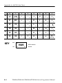
Appendix A: ASCII Code Chart . . . . . . . . . . . . . . . . . . . . . . .
A-- 1
Appendix B: Factory Setup . . . . . . . . . . . . . . . . . . . . . . . . . . .
B-- 1
Glossary and Index
ii
TDS200/TDS1000/TDS2000/TPS2000 Series Programmer Manual
Table of Contents
List of Figures
Figure 2-- 1: Command message elements . . . . . . . . . . . . . . .
2-- 4
Figure 2-- 2: Block Argument example . . . . . . . . . . . . . . . . . . 2-- 13
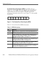
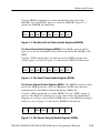
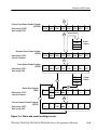
Figure 3-- 1: The Standard Event Status Register (SESR) . .
3-- 2
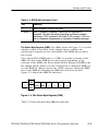
Figure 3-- 2: The Status Byte Register (SBR) . . . . . . . . . . . . .
3-- 3
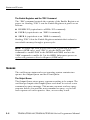
Figure 3-- 3: The Device Event Status Enable Register
(DESER) . . . . . . . . . . . . . . . . . . . . . . . . . . . . . . . . . . . . . . .
3-- 5
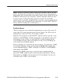
Figure 3-- 4: The Event Status Enable Register (ESER) . . . .
3-- 5
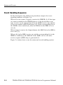
Figure 3-- 5: The Service Request Enable Register (SRER) .
3-- 5
Figure 3-- 6: Status and event handling process . . . . . . . . . . .
3-- 9
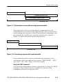
Figure 3-- 7: Command processing without using
synchronization . . . . . . . . . . . . . . . . . . . . . . . . . . . . . . . . . . 3-- 11
Figure 3-- 8: Processing sequence with synchronization . . . . 3-- 11
List of Tables
Table 1-- 1: Communications ports and functions . . . . . . . . .
1-- 1
Table 1-- 2: Oscilloscope and module compatibility . . . . . . .
1-- 2
Table 2-- 1: Oscilloscope communication protocol . . . . . . . .
2-- 1
Table 2-- 2: BNF notation . . . . . . . . . . . . . . . . . . . . . . . . . . . .
2-- 2
Table 2-- 3: Command message elements . . . . . . . . . . . . . . . .
2-- 3
Table 2-- 4: Comparison of Header Off and Header On
responses . . . . . . . . . . . . . . . . . . . . . . . . . . . . . . . . . . . . . . .
2-- 5
Table 2-- 5: Types of numeric arguments . . . . . . . . . . . . . . . . 2-- 11
Table 2-- 6: Oscilloscope handling of incorrect numeric
arguments . . . . . . . . . . . . . . . . . . . . . . . . . . . . . . . . . . . . . . 2-- 11
Table 2-- 7: Parts of a block argument . . . . . . . . . . . . . . . . . . 2-- 13
Table 2-- 8: Acquisition commands . . . . . . . . . . . . . . . . . . . . . 2-- 15
Table 2-- 9: Calibration and Diagnostic commands . . . . . . . 2-- 16
Table 2-- 10: Cursor commands . . . . . . . . . . . . . . . . . . . . . . . 2-- 17
TDS200/TDS1000/TDS2000/TPS2000 Series Programmer Manual
iii
Table of Contents
Table 2-- 11: Display commands . . . . . . . . . . . . . . . . . . . . . . . 2-- 18
Table 2-- 12: File System commands . . . . . . . . . . . . . . . . . . . 2-- 19
Table 2-- 13: Hard Copy commands . . . . . . . . . . . . . . . . . . . . 2-- 20
Table 2-- 14: Horizontal commands . . . . . . . . . . . . . . . . . . . . 2-- 21
Table 2-- 15: Math commands . . . . . . . . . . . . . . . . . . . . . . . . . 2-- 22
Table 2-- 16: Measurement commands
. . . . . . . . . . . . . . . . . 2-- 23
Table 2-- 17: Miscellaneous commands . . . . . . . . . . . . . . . . . 2-- 25
Table 2-- 18: Power and Battery-Related commands . . . . . . 2-- 27
Table 2-- 19: Power Measurement commands . . . . . . . . . . . . 2-- 28
Table 2-- 20: RS-232 commands . . . . . . . . . . . . . . . . . . . . . . . 2-- 32
Table 2-- 21: Save and Recall commands . . . . . . . . . . . . . . . . 2-- 33
Table 2-- 22: Status and Error commands . . . . . . . . . . . . . . . 2-- 34
Table 2-- 23: Trigger commands . . . . . . . . . . . . . . . . . . . . . . . 2-- 35
Table 2-- 24: Vertical commands . . . . . . . . . . . . . . . . . . . . . . . 2-- 37
Table 2-- 25: Waveform commands . . . . . . . . . . . . . . . . . . . . 2-- 38
Table 2-- 26: Binary data ranges . . . . . . . . . . . . . . . . . . . . . . . 2-- 42
Table 2-- 27: Vertical position ranges using a 1X probe . . . . 2-- 67
Table 2-- 28: DATa and WFMPre parameter settings . . . . . 2-- 88
Table 2-- 29: Commands that generate an Operation
Complete message . . . . . . . . . . . . . . . . . . . . . . . . . . . . . . . 2-- 166
Table 2-- 30: Additional WFMPre commands . . . . . . . . . . . . 2-- 248
Table 3-- 1: SESR bit functions . . . . . . . . . . . . . . . . . . . . . . . .
3-- 2
Table 3-- 2: SBR bit functions . . . . . . . . . . . . . . . . . . . . . . . . .
3-- 4
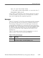
Table 3-- 3: No event messages . . . . . . . . . . . . . . . . . . . . . . . . 3-- 17
Table 3-- 4: Command error messages – CME bit 5 . . . . . . . 3-- 18
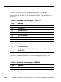
Table 3-- 5: Execution error messages – EXE bit 4 . . . . . . . . 3-- 18
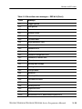
Table 3-- 6: Device error messages – DDE bit 3 . . . . . . . . . . 3-- 22
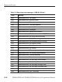
Table 3-- 7: System event messages . . . . . . . . . . . . . . . . . . . . . 3-- 22
Table 3-- 8: Execution warning messages – EXE Bit 4 . . . . . 3-- 23
Table 3-- 9: Internal warning messages . . . . . . . . . . . . . . . . . 3-- 24
iv
TDS200/TDS1000/TDS2000/TPS2000 Series Programmer Manual
Preface
This programmer manual provides information on how to remotely
operate your TDS200, TDS1000, TDS2000, or TPS2000 series
oscilloscope. You can use communication ports and protocols, such
as for the RS-232 and the General Purpose Interface Bus (GPIB)
standards, to remotely control and operate your oscilloscope.
Related Documents
Each series of oscilloscopes has a different set of documentation.
TPS2000 Series Manuals
For general operation, refer to the TPS2000 Series Digital Storage
Oscilloscope User Manual, a standard accessory.
Language
TPS2000 series user manual part number
English
071-1441-XX
French
071-1442-XX
Italian
071-1443-XX
German
071-1444-XX
Spanish
071-1445-XX
Japanese
071-1446-XX
Portuguese
071-1447-XX
Simplified Chinese
071-1448-XX
Traditional Chinese
071-1449-XX
Korean
071-1450-XX
Russian
071-1451-XX
For information on the TPS2PWR1 Power Analysis Application,
refer to the TPS2PWR1 Power Analysis Application User Manual, an
optional accessory available in eleven languages.
TDS200/TDS1000/TDS2000/TPS2000 Series Programmer Manual
v
Preface
Language
TDS2PWR1 user manual part number
English
071-1452-XX
French
071-1453-XX
Italian
071-1454-XX
German
071-1455-XX
Spanish
071-1456-XX
Japanese
071-1457-XX
Portuguese
071-1458-XX
Simplified Chinese
071-1459-XX
Traditional Chinese
071-1460-XX
Korean
071-1461-XX
Russian
071-1462-XX
TDS1000 and TDS2000 Series Manuals
For general operation, and information on the TDS2CMA Communications module, refer to the TDS1000 and TDS2000 Series Digital
Storage Oscilloscope User Manual, a standard accessory.
Language
TDS1000/TDS2000 series user manual part number
English
071-1064-XX
French
071-1065-XX
Italian
071-1066-XX
German
071-1067-XX
Spanish
071-1068-XX
Japanese
071-1069-XX
Portuguese
071-1070-XX
Simplified Chinese
071-1071-XX
Traditional Chinese 071-1072-XX
vi
Korean
071-1073-XX
Russian
071-1074-XX
TDS200/TDS1000/TDS2000/TPS2000 Series Programmer Manual
Preface
For information on the TDS2MEM Storage Memory and Communications module, refer to the TDS2MEM Storage Memory and
Communications Module User Manual (071-- 1262-- XX), an optional
accessory that includes all eleven languages.
TDS200 Series Manuals
For general operation, refer to the TDS200 Series Digital Real-Time
Oscilloscope User Manual, a standard accessory.
Language
TDS200 series user manual part number
English
071-0398-XX
French
071-0400-XX
Italian
071-0401-XX
German
071-0402-XX
Spanish
071-0399-XX
Japanese
071-0405-XX
Portuguese
071-0403-XX
Simplified Chinese
071-0406-XX
Traditional Chinese
071-0407-XX
Korean
071-0408-XX
Russian
071-0404-XX
For information on the TDS2CMA Communications module, or
TDS2MM Math Measurements module, refer to the TDS200 Series
Extension Modules Instructions Manual (071-0409-XX), a standard
accessory for extension modules in English only.
TDS200/TDS1000/TDS2000/TPS2000 Series Programmer Manual
vii
Preface
Service Manuals (English Only)
For information on how to service your oscilloscope, refer to the
appropriate manual from the following optional accessories:
H TPS2000 Series Digital Storage Oscilloscopes Service Manual
(071-1465-XX)
H TDS1000 and TDS2000 Series Digital Storage Oscilloscopes
Service Manual (071-1076-XX)
H TDS200 Series Digital Real-Time Oscilloscopes Service Manual
(071-0492-XX)
Conventions
Refer to the Command Syntax section of the Syntax and Commands
chapter (page 2-- 1) for information about command conventions.
This manual uses the following conventions:
H References to the TDS2CMA Communications Extension
Module include the TDS2CM and TDS2CMAX modules.
H References to the TDS1002 and TDS1012 models include the
TDS1001
H References to the TDS2014 and TDS2024 models include the
TDS2004
viii
TDS200/TDS1000/TDS2000/TPS2000 Series Programmer Manual
Getting Started
Getting Started
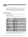
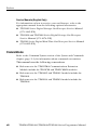
This manual contains information on how to remotely control and
operate your oscilloscope through communications protocol and
commands. First, you need to connect an appropriate cable between
the communications port on your oscilloscope and your PC.
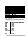
The next table describes where the communications port is located
on an extension module or oscilloscope, and the function of the port.
Table 1- 1: Communications ports and functions
Series
Port location
Port function
TDS200
TDS2CM, TDS2CMA, or TDS2CMAX RS--232, Centronics, GPIB
Communications, TDS2MM Math
TDS1000/ TDS2CMA or TDS2CMAX
TDS2000*
TDS2MEM Storage Memory and
Communications
RS--232, Centronics, GPIB
TPS2000
RS--232, Centronics
Back of oscilloscope
RS--232, Centronics, CompactFlash
*TDS1001 and TDS2004 models are not compatible with the TDS2MEM module.
Refer to your oscilloscope user manual (Tektronix part numbers
listed on page v) for information on how to install, test, and
configure your oscilloscope and module.
NOTE. The firmware for the TPS2000 series oscilloscopes includes
communications, math, and storage memory functions.
TDS200/TDS1000/TDS2000/TPS2000 Series Programmer Manual
1- 1
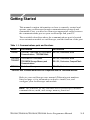
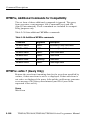
Getting Started
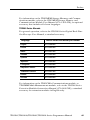
Table 1- 2: Oscilloscope and module compatibility
1- 2
Oscilloscope series
TDS2CM,TDS2CMA
or TDS2CMAX
TDS200
TDS1000/TDS2000
Yes
TDS2MM
Yes
TDS2MEM
No
Yes
No*
Yes{
*
Function included in the oscilloscope firmware.
{
TDS1001 and TDS2004 models are not compatible with the
TDS2MEM module.
TDS200/TDS1000/TDS2000/TPS2000 Series Programmer Manual
Syntax and Commands
Command Syntax
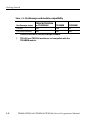
You can control the oscilloscope through the GPIB or RS-232
interface using a large group of commands and queries.
This section describes the syntax these commands and queries use
and the conventions the oscilloscope uses to process them. The
commands and queries themselves are listed in the Command
Descriptions section.
Table 2- 1: Oscilloscope communication protocol
Model or option
GPIB
RS-232
TDS2CM(A)
Yes
Yes
TDS2MM
Yes
Yes
TDS2MEM
No
Yes
TPS2000
No
Yes
You transmit commands to the oscilloscope using the enhanced
American Standard Code for Information Interchange (ASCII)
character encoding. Appendix A contains a chart of the ASCII
character set.
TDS200/TDS1000/TDS2000/TPS2000 Series Programmer Manual
2- 1
Command Syntax
The Backus Naur Form (BNF) notation is used in this manual to
describe commands and queries. Table 2-- 2 lists the BNF notation.
Table 2- 2: BNF notation
Symbol
Meaning
<>
Defined element
::=
Is defined as
|
Exclusive OR
{}
Group; one element is required
[]
Optional; can be omitted
...
Previous element(s) may be
repeated
()
Comment
Command and Query Structure
Commands consist of set commands and query commands (usually
simply called commands and queries). Commands change oscilloscope settings or perform a specific action. Queries cause the
oscilloscope to return data and information about its status.
Most commands have both a set form and a query form. The query
form of the command is the same as the set form except that it ends
with a question mark. For example, the set command ACQuire:MODe
has a query form ACQuire:MODe?. Not all commands have both a set
and a query form; some commands are set only and some are query
only.
A few commands do both a set and query action. For example, the
*CAL? command runs a self-calibration program on the oscilloscope,
then returns the result of the calibration.
A command message is a command or query name, followed by any
information the oscilloscope needs to execute the command or query.
Command messages consist of five different element types.
2- 2
TDS200/TDS1000/TDS2000/TPS2000 Series Programmer Manual
Command Syntax
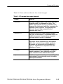
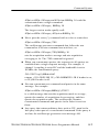
Table 2-- 3 lists and describes the five element types.
Table 2- 3: Command message elements
Symbol
Meaning
<Header>
The basic command name. If the header ends with
a question mark, the command is a query. The
header may begin with a colon (:) character; if the
command is concatenated with other commands the
beginning colon is required. The beginning colon
can never be used with command headers
beginning with a star (*).
<Mnemonic>
A header subfunction. Some command headers
have only one mnemonic. If a command header has
multiple mnemonics, they are always separated
from each other by a colon (:) character.
<Argument>
A quantity, quality, restriction, or limit associated with
the header. Not all commands have an argument,
while other commands have multiple arguments.
Arguments are separated from the header by a
<Space>. Arguments are separated from each
other by a <Comma>.
<Comma>
A single comma between arguments of multiple-argument commands. It may optionally have white
space characters before and after the comma.
<Space>
A white space character between command header
and argument. It may optionally consist of multiple
white space characters.
TDS200/TDS1000/TDS2000/TPS2000 Series Programmer Manual
2- 3
Command Syntax
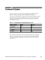
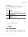
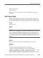
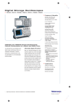
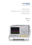
Figure 2-- 1 shows the five command message elements.
Header
Comma
SAVe:WAVEform CH1,REFA
Mnemonics
Arguments
Space
Figure 2- 1: Command message elements
Commands
Commands cause the oscilloscope to perform a specific function or
change one of its settings. Commands have the structure:
[:]<Header>[<Space><Argument>[<Comma><Argument>]...]
A command header is made up of one or more mnemonics arranged
in a hierarchical or tree structure. The first mnemonic is the base or
root of the tree and each subsequent mnemonic is a level or branch
off of the previous one. Commands at a higher level in the tree may
affect those at a lower level. The leading colon (:) always returns
you to the base of the command tree.
Queries
Queries cause the oscilloscope to return information about its status
or settings. Queries have the structure:
[:]<Header>?
[:]<Header>?[<Space><Argument>[<Comma><Argument>]...]
You can specify a query command at any level within the command
tree unless otherwise noted. These branch queries return information
about all the mnemonics below the specified branch or level. For
example, MEASUrement:MEAS<x>:UNIts? returns the measurement
units, while MEASUrement:MEAS<x>:TYPe? returns the measurement
type selected for the measurement, and MEASUrement:MEAS<x>?
2- 4
TDS200/TDS1000/TDS2000/TPS2000 Series Programmer Manual
Command Syntax
returns all the measurement parameters for the specified measurement.
Headers in Query Responses
You can control whether the oscilloscope returns headers as part of
the query response. Use the HEADer command to control this feature.
If header is on, the oscilloscope returns command headers as part of
the query and formats the query response as a valid set command.
When header is off, the oscilloscope sends back only the values in
the response. This format can make it easier to parse and extract the
information from the response.
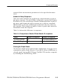
Table 2-- 4 shows the difference in responses.
Table 2- 4: Comparison of Header Off and Header On responses
Query
Header Off response
Header On response
ACQuire:NUMAVg?
64
:ACQUIRE:NUMAVG 64
CHx1:COUPling?
DC
:CH1:COUPLING DC
Clearing the Output Queue
To clear the output queue and reset the oscilloscope to accept a new
command or query, send a Device Clear (DCL) from a GPIB host or
a break signal from an RS-232 host. The RS-- 232 interface responds
by returning the ASCII string “DCL”.
TDS200/TDS1000/TDS2000/TPS2000 Series Programmer Manual
2- 5
Command Syntax
Command Entry
Follow these general rules when entering commands:
H Enter commands in upper or lower case.
H You can precede any command with white space characters.
White space characters include any combination of the ASCII
control characters 00 through 09 and 0B through 20 hexadecimal
(0 through 9 and 11 through 32 decimal).
H The oscilloscope ignores commands that consists of just a
combination of white space characters and line feeds.
Abbreviating Commands
You can abbreviate many oscilloscope commands. These abbreviations are shown in capital letters in the command listing in the
Command Groups section on page 2-- 15 and Command Descriptions
section on page 2-- 45. For example, the command ACQuire:NUMAvg
can be entered simply as ACQ:NUMA or acq:numa.
If you use the HEADer command to have command headers included
as part of query responses, you can also control whether the returned
headers are abbreviated or are full-length using the VERBose
command.
Concatenating Commands
You can concatenate any combination of set commands and queries
using a semicolon (;). The oscilloscope executes concatenated
commands in the order received. When concatenating commands
and queries you must follow these rules:
H Completely different headers must be separated by both a
semicolon and by the beginning colon on all commands but the
first. For example, the commands TRIGger:MODe NORMal and
ACQuire:NUMAVg 16 can be concatenated into a single
command:
TRIGger:MODe NORMal;:ACQuire:NUMAVg 16
H If concatenated commands have headers that differ by only the
last mnemonic, you can abbreviate the second command and
eliminate the beginning colon. For example, the commands
2- 6
TDS200/TDS1000/TDS2000/TPS2000 Series Programmer Manual
Command Syntax
ACQuire:MODe AVErage and ACQuire:NUMAVg 16 could be
concatenated into a single command:
ACQuire:MODe AVErage; NUMAVg 16
The longer version works equally well:
ACQuire:MODe AVErage;:ACQuire:NUMAVg 16
H Never precede a star (*) command with a colon or semicolon:
ACQuire:MODe AVErage;*TRG
The oscilloscope processes commands that follow the star
command as if the star command was not there, so:
ACQuire:MODe AVErage;*TRG;NUMAVg 16
sets the acquisition mode to average and sets acquisition
averaging to 16. The *TRG command is ignored.
H When you concatenate queries, the responses to all queries are
combined into a single response message. For example, if
channel 1 coupling is set to DC and the bandwidth is set to
20 MHz, the concatenated query:
CH1:COUPling?;BANdwidth?
returns :CH1:COUPLING DC;:CH1:BANDWIDTH ON if header is on,
or DC;ON if header is off.
H You can concatenate set commands and queries in the same
message. For example:
ACQuire:MODe AVErage;NUMAVg?;STATE?
is a valid message that sets the acquisition mode to average,
queries the number of acquisitions for averaging, and then
queries the acquisition state. The oscilloscope executes
concatenated commands and queries in the order it receives
them.
H Any query that returns arbitrary data, such as ID?, must be the
last query when part of a concatenated command. If the query is
not last, the oscilloscope generates event message 440.
TDS200/TDS1000/TDS2000/TPS2000 Series Programmer Manual
2- 7
Command Syntax
Here are some INVALID concatenation examples:
H CH1:COUPling DC;ACQuire:NUMAVg 16
(missing colon before ACQuire)
H CH1:COUPling DC;:BANDwidth ON
(invalid colon before BANDwidth)
H CH1:COUPling DC;:*TRG
(invalid colon before a star (*) command)
H HORizontal:MAIn:POSition 0;MAIn:SCAle 1E–13
(levels of mnemonics are different—either remove the second
occurrence of MAIn:, or put :HORizontal: in front of
MAIN:SCAle)
Message Terminators
This manual uses the term <EOM> (End of message) to represent a
message terminator.
GPIB End of Message Terminators. GPIB EOM terminators can be the
END message (EOI asserted concurrently with the last data byte),
the ASCII code for line feed (LF) sent as the last data byte, or both.
The oscilloscope always terminates messages with LF and EOI.
White space is allowed before the terminator; for example, CR LF is
acceptable.
RS-232 End of Message Terminators. RS-232 EOM terminators can be a
CR (carriage return), LF (line feed), CRLF (carriage return followed
by a line feed), or LFCR (line feed followed by a carriage return).
When receiving, the oscilloscope accepts all four combinations as
valid input message terminators regardless of the currently selected
terminator. When a combination of multiple characters is selected
(CRLF or LFCR), the oscilloscope interprets the first character as the
terminator and the second character as a null command.
2- 8
TDS200/TDS1000/TDS2000/TPS2000 Series Programmer Manual
Command Syntax
Constructed Mnemonics
Some header mnemonics specify one of a range of mnemonics. For
example, a channel mnemonic could be CH2. You can use these
mnemonics in the command just as you do any other mnemonic. For
example, there is a CH1:VOLts command and there is also a
CH2:VOLts command. In the command descriptions, this list of
choices is abbreviated CH<x>.
Channel Mnemonics
Commands specify the channel to use as a mnemonic in the header.
Symbol
Meaning
CH<x>
2-channel models: A channel specifier; <x> is 1 or 2.
4-channel models: A channel specifier; <x> is 1, 2,
3, or 4.
Reference Waveform Mnemonics
Commands can specify the reference waveform to use as a
mnemonic in the header.
Symbol
Meaning
REF<x>
2-channel models: A reference waveform specifier;
<x> is A or B.
4-channel models: A reference waveform specifier;
<x> is A, B, C, or D.
Waveform Mnemonics
In some commands you can specify a waveform without regard to its
type: channel waveform, math waveform, or reference waveform.
The “y” is the same as “x” in Reference Waveform Mnemonics.
Symbol
Meaning
<wfm>
Can be CH<x>, MATH, or REF<y>
TDS200/TDS1000/TDS2000/TPS2000 Series Programmer Manual
2- 9
Command Syntax
Cursor Position Mnemonic
When the oscilloscope displays cursors, commands may specify
which cursor of the pair to use.
Symbol
Meaning
POSITION<x>
A cursor selector; <x> is 1 or 2.
Measurement Specifier Mnemonics
Commands can specify which measurement to set or query as a
mnemonic in the header. The oscilloscope can display up to four
(TDS200 Series) or five (TDS1000, TDS2000, TPS2000 Series)
automated measurements.
Symbol
Meaning
MEAS<x>
A measurement specifier; <x> is 1--4 (TDS200
Series) or 1--5 (TDS1000, TDS2000, and TPS2000
Series).
Argument Types
A command argument can be in one of several forms. The individual
descriptions of each command tell which argument types to use with
that command.
Numeric Arguments
Many oscilloscope commands require numeric arguments. Table 2-- 5
lists the three types of numeric argument.
2- 10
TDS200/TDS1000/TDS2000/TPS2000 Series Programmer Manual
Command Syntax
Table 2- 5: Types of numeric arguments
Symbol
Meaning
<NR1>
Signed integer value
<NR2>
Floating point value without an exponent
<NR3>
Floating point value with an exponent
The syntax shown is the data format that the oscilloscope returns in
response to a query. This format is also the preferred format when
sending a command to the oscilloscope.
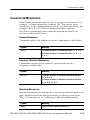
When you enter an incorrect numeric argument, the oscilloscope
automatically forces the numeric argument to a correct value.
Table 2-- 6 lists how the oscilloscope handles incorrect numeric
arguments.
Table 2- 6: Oscilloscope handling of incorrect numeric arguments
Argument value
Oscilloscope response
Numeric argument is
less than lowest correct
value for that command
Sets the specified command to the lowest correct
value and executes the command
Numeric argument is
greater than the highest
correct value for that
command
Sets the specified command to the highest correct
value and executes the command
Numeric value is beRounds the entered value to the nearest correct
tween two correct values value and executes the command
Quoted String Arguments
Some commands accept or return data in the form of a quoted string,
which is simply a group of ASCII characters enclosed by single
quotes (’) or double quotes (”). For example:
”this is a quoted string”
TDS200/TDS1000/TDS2000/TPS2000 Series Programmer Manual
2- 11
Command Syntax
Symbol
Meaning
<QString>
Quoted string of ASCII text
Follow these rules when you use quoted strings:
1. A quoted string can include any character defined in the 7-bit
ASCII character set. Refer to Appendix A.
2. Use the same type of quote character to open and close the string:
”this is a valid string”
3. You can mix quotation marks within a string as long as you
follow the previous rule:
”this is an ’acceptable’ string”
4. You can include a quote character within a string simply by
repeating the quote. For example,
”here is a ”” mark”
5. Strings can have upper or lower case characters.
6. If you use a GPIB network, you cannot terminate a quoted string
with the END message before the closing delimiter.
7. A carriage return or line feed embedded in a quoted string does
not terminate the string, but is treated as just another character in
the string.
8. The maximum length of a quoted string returned from a query is
1000 characters.
Here are some examples of invalid strings:
”Invalid string argument’
(quotes are not of the same type)
”test<EOI>”
(termination character is embedded in the string)
2- 12
TDS200/TDS1000/TDS2000/TPS2000 Series Programmer Manual
Command Syntax
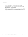
Block Arguments
Several oscilloscope commands use a block argument form.
Table 2-- 7 lists and describes each part of a block argument.
Table 2- 7: Parts of a block argument
Symbol
Meaning
<NZDig>
A non-zero digit character, in the range 1–9
Specifies the number of <Dig> elements that follow
<Dig>
A digit character, in the range 0–9
<DChar>
A character with the hex equivalent of 00 through FF hexadecimal
(0 through 255 decimal)
<Block>
A block of data bytes, defined as:
<Block> ::=
{ #<NZDig><Dig>[<Dig>...][<DChar>...]
| #0[<DChar>...]<terminator> }
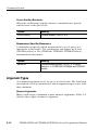
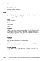
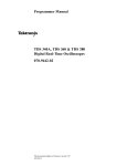
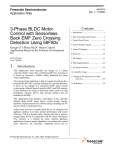
Figure 2-- 2 shows an example of a block argument.
Block argument
*DDT #217ACQuire:STATE RUN
Block header
Specifies data length
Specifies number of
length digits that follow
Figure 2- 2: Block Argument example
<NZDig> specifies the number of <Dig> elements that follow. Taken
together, the <Dig> elements form a decimal integer that specifies
how many <DChar> elements follow.
TDS200/TDS1000/TDS2000/TPS2000 Series Programmer Manual
2- 13
Command Syntax
#0 means that the <Block> is an indefinite length block. The
<terminator> ends the block. You should not use indefinite length
blocks with RS-232, because there is no way to include a <terminator> character as a <DChar> character.
The first occurrence of a <terminator> character signals the end of
the block and any subsequent <DChar> characters will be interpreted
as a syntax error. With the GPIB, the EOI line signals the last byte.
2- 14
TDS200/TDS1000/TDS2000/TPS2000 Series Programmer Manual
Command Groups
This section lists the commands organized by functional group. The
Command Descriptions section, starting on page 2-- 45, lists all
commands alphabetically.
The oscilloscope GPIB and RS-232 interfaces conform to Tektronix
standard codes and formats except where noted. The GPIB interface
also conforms to IEEE Std 488.2–1987 except where noted.
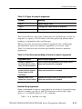
Acquisition Commands
Acquisition commands affect the acquisition of waveforms. These
commands control mode, averaging, and single-waveform
acquisition. Table 2-- 8 lists and describes Acquisition commands.
Table 2- 8: Acquisition commands
Header
Description
ACQuire?
Return acquisition parameters
ACQuire:MODe
Set or query the acquisition mode
ACQuire:NUMACq?
Return the # of acquisitions obtained
ACQuire:NUMAVg
Set or query the number of acquisitions
for average
ACQuire:STATE
Start or stop the acquisition system
ACQuire:STOPAfter
Set or query the acquisition control
TDS200/TDS1000/TDS2000/TPS2000 Series Programmer Manual
2- 15
Command Groups
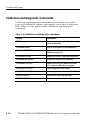
Calibration and Diagnostic Commands
Calibration and Diagnostic commands let you initiate the oscilloscope self-calibration routines and examine the results of diagnostic
tests. Table 2-- 9 lists and describes Calibration and Diagnostic
commands.
Table 2- 9: Calibration and Diagnostic commands
2- 16
Header
Description
*CAL?
Perform an internal self-calibration and
return result status
CALibrate:ABOrt
Stop an in-progress factory calibration
CALibrate:CONTINUE
Perform the next step in the factory
calibration sequence
CALibrate:FACtory
Initialize the factory calibration sequence
CALibrate:INTERNAL
Perform an internal self-calibration
CALibrate:STATUS?
Return PASS or FAIL status of the last
self- or factory-calibration operation
DIAg:RESUlt:FLAG?
Return diagnostic tests status
DIAg:RESUlt:LOG?
Return diagnostic test sequence results
ERRLOG:FIRST?
Returns first entry from error log
ERRLOG:NEXT?
Returns next entry from error log
TDS200/TDS1000/TDS2000/TPS2000 Series Programmer Manual
Command Groups
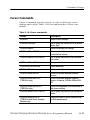
Cursor Commands
Cursor commands provide control over the oscilloscope cursor
display and readout. Table 2-- 10 lists and describes Cursor commands.
Table 2- 10: Cursor commands
Header
Description
CURSor?
Return cursor settings
CURSor:FUNCtion
Set or query the cursors on or off; select
cursor type
CURSor:HBArs?
Return horizontal bar settings
CURSor:HBArs:DELTa?
Return vertical distance between
horizontal bar cursors
CURSor:HBArs:POSITION<x>
Set or query the position of a horizontal
bar cursor
CURSor:HBArs:UNIts?
Query vertical scale units
CURSor:SELect:SOUrce
Select waveform
CURSor:VBArs?
Return vertical bar settings
CURSor:VBArs:DELTa?
Return horizontal distance between
cursors
CURSor:VBArs:HDELTa?
(TPS2000 only)
Return horizontal distance between
cursors. Same as CURSor:VBArs:DELTa?
CURSor:VBArs:HPOS<x>?
(TPS2000 only)
Return the amplitude of the waveform at
the cursor position
CURSor:VBArs:POSITION<x>
Set or query the position of a vertical bar
cursor
CURSor:VBArs:SLOPE?
(TPS2000 with Power Analysis
Module only)
Return the value of the on-screen dV/dt
or dI/dt measurement
TDS200/TDS1000/TDS2000/TPS2000 Series Programmer Manual
2- 17
Command Groups
Table 2- 10: Cursor commands (Cont.)
Header
Description
CURSor:VBArs:UNIts
Set or query the vertical cursors to time
or frequency
CURSor:VBArs:VDELTa?
(TPS2000 only)
Return the vertical distance between
cursors
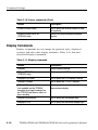
Display Commands
Display commands let you change the graticule style, displayed
contrast, and alter other display attributes. Table 2-- 11 lists and
describes Display commands.
Table 2- 11: Display commands
2- 18
Header
Description
DISplay?
Return display settings
DISplay:BRIGHTness
(TPS2000 only)
Set or query the LCD display brightness
DISplay:CONTRast
Set or query the LCD display contrast
DISplay:FORMat
Set or query the YT or XY display
DISplay:INVert
(not available on the TDS200,
accepted as a legal command on
the TPS2000 but has no effect on
these models)
Set or query the normal or inverted
monochrome display
DISplay:PERSistence
Set or query the accumulate time
DISplay:STYle
Set or query the waveform display style
TDS200/TDS1000/TDS2000/TPS2000 Series Programmer Manual
Command Groups
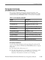
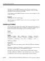
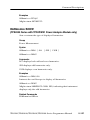
File System Commands
(TDS2MEM Module and TPS2000 Only)
File system commands perform file management tasks on the
CompactFlash (CF) card of TPS2000 Series oscilloscopes or TDS
Series models with TDS2MEM. Table 2-- 12 lists these commands.
Table 2- 12: File System commands
Header
Description
FILESystem?
Return the current working directory
(CWD) and CF free space values
FILESystem:CWD
Set or query the current CF card
directory
FILESystem:DELEte
Delete specified file on the CF card
FILESystem:DIR?
Return a list of files in current CF card
directory
FILESystem:FORMat
Format the CF card
FILESystem:FREESpace?
Return free space on the CF card
FILESystem:MKDir
Create a new directory on the CF card
FILESystem:REName
Assign new name to specified file on the
CF card
FILESystem:RMDir
Delete specified directory
File System Conventions
Use the following information when specifying file paths and file
names for use with the TPS2000 and TDS2MEM module CompactFlash card:
H The default folder (directory) is A:\.
H File and folder names have a maximum of 11 characters; eight
characters, followed by a period, followed by up to three
characters. This format is referred to as 8.3 naming.
TDS200/TDS1000/TDS2000/TPS2000 Series Programmer Manual
2- 19
Command Groups
H Wild card characters (*, %, ?) are not valid characters in file or
path names.
H The TPS2000 and TDS2MEM display the Windows-generated
short file and folder names for long file or folder names created
on PC Windows operating systems.
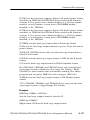
Hard Copy Commands
The hard copy commands let you control the format of hard copy
output and control the starting and stopping of hard copies.
Table 2-- 13 lists and describes Hard Copy commands.
Table 2- 13: Hard Copy commands
Header
Description
HARDCopy
Start or terminate hard copy
HARDCopy:BUTTON
(TDS2MEM module and TPS2000
only)
Set or query the hardcopy button
function
HARDCopy:FORMat
Set or query the hard copy output format
HARDCopy:INKSaver
(TDS1000, TDS2000, TPS2000
only)
Set or query the hard copy ink saver
option
HARDCopy:LAYout
Set or query the hard copy orientation
HARDCopy:PORT
Set or query the hard copy port for
output, RS232, GPIB, or Centronics
The TDS2MEM and TPS2000 do not
have a GPIB port
2- 20
TDS200/TDS1000/TDS2000/TPS2000 Series Programmer Manual
Command Groups
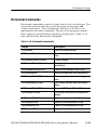
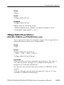
Horizontal Commands
Horizontal commands control the time bases of the oscilloscope. You
can set the position and time per division of both the main and
window time bases. You can substitute SECdiv for SCAle in all
appropriate horizontal commands. This provides program compatibility with previous Tektronix digitizing oscilloscopes. Table 2-- 14
lists and describes Horizontal commands.
Table 2- 14: Horizontal commands
Header
Description
HORizontal?
Return horizontal settings
HORizontal:DELay?
Return all settings for the window time
base
HORizontal:DELay:POSition
Position window
HORizontal:DELay:SCAle
Set or query the window time base
time/division
HORizontal:DELay:SECdiv
Same as HORizontal:DELay:SCAle
HORizontal:MAIn?
Return the main time base time/division
HORizontal:MAIn:POSition
Set or query the main time base trigger
point
HORizontal:MAIn:SCAle
Set or query the main time base time/division
HORizontal:MAIn:SECdiv
Same as HORizontal:MAIn:SCAle
HORizontal:POSition
Set or query the position of waveform to
display
HORizontal:RECOrdlength
Return waveform record length
HORizontal:SCAle
Same as HORizontal:MAIn:SCAle
HORizontal:SECdiv
Same as HORizontal:MAIn:SCAle
HORizontal:VIEW
Select view
TDS200/TDS1000/TDS2000/TPS2000 Series Programmer Manual
2- 21
Command Groups
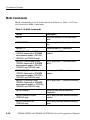
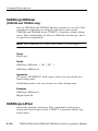
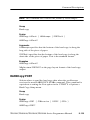
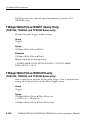
Math Commands
Math commands provide math function definition. Table 2-- 15 lists
and describes Math commands.
Table 2- 15: Math commands
2- 22
Header
Description
MATH?
Query the definition for the math waveform
MATH:DEFINE
Set or query the math waveform definition
MATH:FFT?
Return all math FFT parameters
MATH:FFT:HORizontal:POSition
(TDS200 Series with a TDS2MM
measurement module, TDS1000,
TDS2000, and TPS2000 only)
Set or query the FFT horizontal display
position
MATH:FFT:HORizontal:SCAle
(TDS200 Series with a TDS2MM
measurement module, TDS1000,
TDS2000, and TPS2000 only)
Set or query the FFT horizontal zoom
factor
MATH:FFT:VERtical:POSition
(TDS200 Series with a TDS2MM
measurement module, TDS1000,
TDS2000, and TPS2000 only)
Set or query the FFT vertical display
position
MATH:FFT:VERtical:SCAle
(TDS200 Series with a TDS2MM
measurement module or TDS1000,
TDS2000, and TPS2000 only)
Set or query the FFT vertical zoom factor
MATH:VERtical?
Return all math vertical waveform
parameters
MATH:VERtical:POSition
(TPS2000 only)
Set or query the math waveform display
position
MATH:VERtical:SCAle
(TPS2000 only)
Set or query the math waveform display
scale
TDS200/TDS1000/TDS2000/TPS2000 Series Programmer Manual
Command Groups
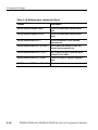
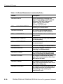
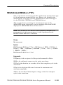
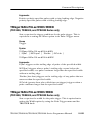
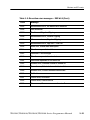
Measurement Commands
Measurement commands control the automated measurement
system. Up to four (TDS200 Series) or five (TDS1000, TDS2000,
and TPS2000 Series) automated measurements can be displayed on
the oscilloscope screen. In the commands, these measurement
readouts are named MEAS<x>, where <x> can be 1, 2, 3, or 4 (or 5
for TDS1000, TDS2000, and TPS2000 Series).
The best method for taking measurements over the computer
interface is to use the MEASUREMENT:IMMED commands and
queries. The immediate measurement has no front-panel equivalent,
and the oscilloscope never displays immediate measurements.
Because they are computed only when they are requested, immediate
measurements slow the waveform update rate less than displayed
measurements.
Use the VALue? query to obtain measurement results of either
displayed or immediate measurements.
Several measurement commands set and query measurement
parameters. You can assign some parameters, such as waveform
sources, differently for each measurement readout.
Table 2-- 16 lists and describes Measurement commands.
Table 2- 16: Measurement commands
Header
Description
MEASUrement?
Return all measurement parameters
MEASUrement:IMMed?
Return immediate measurement parameters
MEASUrement:IMMed:SOUrce1
Set or query the channel for immediate
measurement
MEASUrement:IMMed:SOUrce2
Set or query the channel for two-source
immediate measurements (TPS2000
with Power Analysis Module)
MEASUrement:IMMed:TYPe
Set or query the immediate measurement to be taken
TDS200/TDS1000/TDS2000/TPS2000 Series Programmer Manual
2- 23
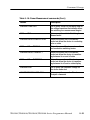
Command Groups
Table 2- 16: Measurement commands (Cont.)
2- 24
Header
Description
MEASUrement:IMMed:UNIts?
Return the immediate measurement
units
MEASUrement:IMMed:VALue?
Return the immediate measurement
result
MEASUrement:MEAS<x>?
Return parameters on the periodic
measurement
MEASUrement:MEAS<x>:SOUrce
Set or query the channel to take the
periodic measurement from
MEASUrement:MEAS<x>:TYPe
Set or query the type of periodic measurement to be taken
MEASUrement:MEAS<x>:UNIts?
Return the units for periodic measurement
MEASUrement:MEAS<x>:VALue?
Return periodic measurement results
TDS200/TDS1000/TDS2000/TPS2000 Series Programmer Manual
Command Groups
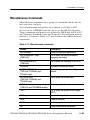
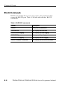
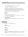
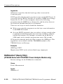
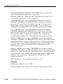
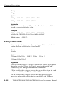
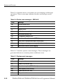
Miscellaneous Commands
Miscellaneous commands are a group of commands that do not fit
into any other category.
Several commands and queries are common to all 488.2–1987
devices on the GPIB BUS and the device on the RS-232 interface.
These commands and queries are defined by IEEE Std. 488.2–1987
and Tektronix Standard Codes and Formats 1989 and begin with an
asterisk (*) character. Table 2-- 17 lists and describes Miscellaneous
commands.
Table 2- 17: Miscellaneous commands
Header
Description
AUTORange?
Return all autorange parameters
AUTORange:SETTings
(TPS2000)
Set or query the which parameters
autorange can adjust
AUTORange:STATE
(TPS2000)
Set or query the autorange to on or off
AUTOSet
Automatic oscilloscope setup
AUTOSet:SIGNAL?
(TDS1000, TDS2000, and
TPS2000 only)
Return the type of signal found by
autoset
AUTOSet:VIEW
(TDS1000, TDS2000, and
TPS2000 only)
Set or query the Autoset view
DATE
(TPS2000 and TDS2MEM module)
Set or query the date value
*DDT
Set or query the group execute trigger
(GET)
FACtory
Reset to factory default
HDR
Same as HEADer
HEADer
Set or query the command header
ID?
Return identification information
TDS200/TDS1000/TDS2000/TPS2000 Series Programmer Manual
2- 25
Command Groups
Table 2- 17: Miscellaneous commands (Cont.)
2- 26
Header
Description
*IDN?
Return identification information
LANGUAGE
Set or query the language for display
messages
LOCk
Lock front panel (local lockout)
*LRN?
Query device settings
REM
No action; remark only
*RST
Reset
SET?
Same as *LRN?
TIME
(TPS2000 and TDS2MEM module)
Set or query the time value
*TRG
Perform Group Execute Trigger (GET)
*TST?
Return self-test results
UNLock
Unlock front panel (local lockout)
VERBose
Return full command name or minimum
spellings with query
TDS200/TDS1000/TDS2000/TPS2000 Series Programmer Manual
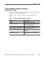
Command Groups
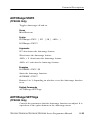
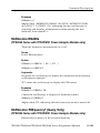
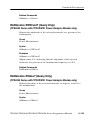
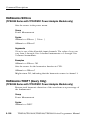
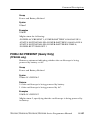
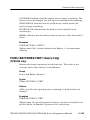
Power and Battery-Related Commands
(TPS2000 Series Only)
Power and Battery-Related commands provide battery management
functions to a TPS2000 oscilloscope.
Table 2-- 18 lists and describes Power and Battery-Related commands.
Table 2- 18: Power and Battery-Related commands
Header
Description
POWer?
Return all power parameters
POWer:AC:PRESENt?
Return whether the oscilloscope is being
powered by battery or AC
POWer:BATTERY<x>:GASgauge?
Return the charge remaining in battery x
POWer:BATTERY<x>:STATUS?
Return status for battery x
POWer:BATTERIES:TIME?
Return the time remaining in both
batteries
POWer:BUTTONLIGHT
Turn the lighted front-panel buttons on
and off
TDS200/TDS1000/TDS2000/TPS2000 Series Programmer Manual
2- 27
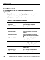
Command Groups
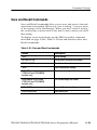
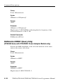
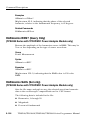
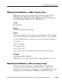
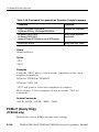
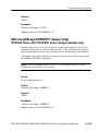
Power Measurement
(TPS2000 Series, TPS2PWR1 Power Analysis Application
Key Installed)
Power Measurement commands provide power measurements to a
TPS2000 oscilloscope with the TPS2PWR1 Power Analysis
application software key installed.
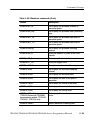
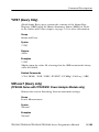
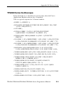
Table 2-- 19 lists and describes Power Measurement commands.
Table 2- 19: Power Measurement commands
2- 28
Header
Description
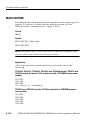
HARmonics?
Return all harmonic parameters
HARmonics:ENABle
Set or query the harmonics menu on and
off
HARmonics:FREquency?
Return the frequency of the selected
harmonic
HARmonics:HRMS?
Return the frequency of the selected
harmonic
HARmonics:PERCent?
Return the amplitude of the selected
harmonic as a percent of the fundamental
HARmonics:PHAse?
Return the phase of the selected
harmonic, in degrees, relative to the
fundamental
HARmonics:RMS?
Return the amplitude of the harmonics
source in RMS units. This may be Vrms
or Irms depending on the type of source
waveform
HARmonics:SAVe
Set the file name and path to save
harmonic data
HARmonics:SELect
Set or query the selected harmonic
HARmonics:SETUp
Set or query the operating mode for
harmonics measurements commands
TDS200/TDS1000/TDS2000/TPS2000 Series Programmer Manual
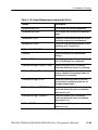
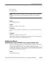
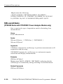
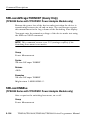
Command Groups
Table 2- 19: Power Measurement commands (Cont.)
Header
Description
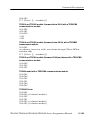
HARmonics:SHOW
Set or query the specified harmonics
HARmonics:SOUrce
Set or query the source in the harmonics
menu
HARmonics:THDF?
Query the total harmonic distortion of the
waveform as percent of fundamental
HARmonics:THDR?
Query the total harmonic distortion of the
waveform as % of input Vrms
POWerANALYSIS:SOUrces
Sets or query the power analysis sources
SWLoss?
Return switching loss measurement
settings
SWLoss:ACQuire
Set or query the type of acquisition to
use for Switching Loss commands
SWLoss:AVErage:CONDUCTION?
Return the power loss of the device
under test when the device is conducting
SWLoss:AVErage:N?
Return the number of measurements
used to calculate the averaged value for
switching loss commands
SWLoss:AVErage:TOTAL?
Return the sum of the turn-on, turn-off,
and conduction switching losses for an
Average measurement
SWLoss:AVErage:TURNOFF?
Return the power loss of the device
under test when the device is transitioning from on to off
SWLoss:AVErage:TURNON?
Return the power loss of the device
under test when the device is transitioning from off to on
SWLoss:ENABLe
Set or query switching loss measurements on or off
TDS200/TDS1000/TDS2000/TPS2000 Series Programmer Manual
2- 29
Command Groups
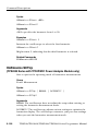
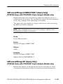
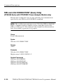
Table 2- 19: Power Measurement commands (Cont.)
2- 30
Header
Description
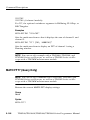
SWLoss:LEVELS
Return oscilloscope Switching Loss
Measurement settings to factory default
(SWLoss:TONSTART, SWLoss:TONEND, SWLoss:TOFFSTART,
SWLoss:TOFFEND only)
SWLoss:LOG:CONDUCTION?
Return the Conduction Loss for a
switching loss measurement
SWLoss:LOG:INDEX
Set or query which measurement to
return for a SWLoss:LOG command
SWLoss:LOG:TOTAL?
Return the Total Loss for a switching loss
measurement
SWLoss:LOG:TURNOFF?
Return the Turn-Off Loss for a switching
loss measurement
SWLoss:LOG:TURNON?
Return the Turn-On Loss for a switching
loss measurement
SWLoss:SAVE
Saves the Switching Loss Measurements
SWLoss:SOURCES
Set or query the input sources for
Switching Loss Measurements
SWLoss:STOPAfter
Set or query the number of acquisitions
used for Switching Loss Measurements
SWLoss:TOFFEND
Set or query a level on the first falling
edge of the current waveform that occurs
after the turn-off starts
SWLoss:TONEND
Set or query a level on the first rising
edge of the voltage waveform that occurs
after the first falling edge
SWLoss:TOFFSTART
Set or query a level on the falling edge of
the voltage waveform that defines where
the beginning of the switching loss
measurement ends
TDS200/TDS1000/TDS2000/TPS2000 Series Programmer Manual
Command Groups
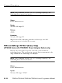
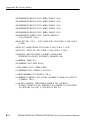
Table 2- 19: Power Measurement commands (Cont.)
Header
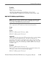
Description
SWLoss:TONSTART
Set or query a level on the falling edge of
the voltage waveform that defines where
the switching loss measurement begins
SWLoss:UNIts
Set or query the units for Switching Loss
Measurement
SWLoss:VALue:CONDUCTION?
Return the power loss of the device
under test when the device is conducting
in its on state
SWLoss:VALue:TOTAL?
Return the sum of the turn-on, turn-off,
and conduction switching losses
SWLoss:VALue:TURNOFF?
Return the power loss of the device
under test when the device is transitioning between its on and off state
SWLoss:VALue:TURNON?
Return the power loss of the device
under test when the device is transitioning between its off and on state display
SWLoss:VSAT
Set or query the saturation voltage for
the device under test
WAVEFORMANALYSIS:SOUrce
Set or query the source for Waveform
Analysis commands
TDS200/TDS1000/TDS2000/TPS2000 Series Programmer Manual
2- 31
Command Groups
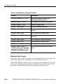
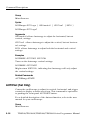
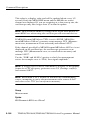
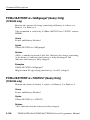
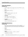
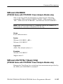
RS-232 Commands
RS-232 commands allow you to set or query the parameters that
control the RS-232 port. Table 2-- 20 lists and describes RS-232
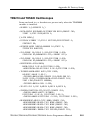
commands.
Table 2- 20: RS-232 commands
2- 32
Header
Description
RS232?
Query RS232 parameters
RS232:BAUd
Set or query the baud rate
RS232:HARDFlagging
Set or query the hard flagging
RS232:PARity
Set or query the parity type
RS232:SOFTFlagging
Set or query the soft flagging
RS232:TRANsmit:TERMinator
Set or query the end-of-line terminator
TDS200/TDS1000/TDS2000/TPS2000 Series Programmer Manual
Command Groups
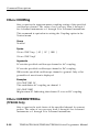
Save and Recall Commands
Save and Recall commands allow you to store and retrieve internal
waveforms and settings. When you “save a setting,” you save most
of the settings of the oscilloscope. When you then “recall a setting,”
the oscilloscope restores itself to the state it was in when you saved
that setting.
To display a saved waveform, use the SELect:<wfm> command
described on page 2-- 186. Table 2-- 21 lists and describes Save and
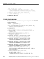
Recall commands.
Table 2- 21: Save and Recall commands
Header
Description
*RCL
Recall setting
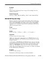
RECAll:SETUp
Recall saved oscilloscope setting
RECAll:WAVEform
Recall saved waveform
*SAV
Save oscilloscope setting
SAVe:IMAge
(TPS2000 and TDS2MEM
module only)
Save screen image to file
SAVe:IMAge:FILEFormat
(TPS2000 and TDS2MEM
module only)
Set screen image file format
SAVe:SETUp
Save oscilloscope setting
SAVe:WAVEform
Save waveform
TDS200/TDS1000/TDS2000/TPS2000 Series Programmer Manual
2- 33
Command Groups
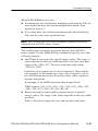
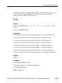
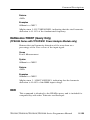
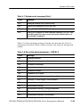
Status and Error Commands
Status and error commands let you determine the status of the
oscilloscope and control events.
Several commands and queries are common to all devices on the
GPIB bus. These commands and queries are defined by IEEE Std.
488.2–1987 and Tek Standard Codes and Formats 1989, and begin
with an asterisk (*) character. Table 2-- 22 lists and describes Status
and Error commands.
Table 2- 22: Status and Error commands
2- 34
Header
Description
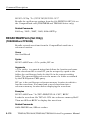
ALLEv?
Return all events
BUSY?
Return oscilloscope busy status
*CLS
Clear status
DESE
Set or query the device event status enable
*ESE
Set or query the standard event status enable
*ESR?
Return standard event status register; this is the usual
way to determine whether a set command executed
without error
EVENT?
Return event code
EVMsg?
Return event message
EVQty?
Return number of events in queue
*OPC
Set or query the operation complete
*PSC
Set or query the power-on status clear
*SRE
Set or query the service request enable
*STB?
Read status byte
*WAI
Wait to continue
TDS200/TDS1000/TDS2000/TPS2000 Series Programmer Manual
Command Groups
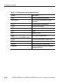
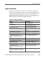
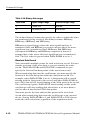
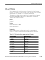
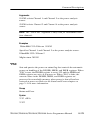
Trigger Commands
Trigger commands control all aspects of oscilloscope triggering.
The two types of triggers are edge and video. Edge triggering is the
default type. Edge triggering lets you acquire a waveform when the
signal passes through a voltage level of your choosing. Video
triggering adds the capability of triggering on video fields and lines.
Table 2-- 23 lists and describes Trigger commands.
Table 2- 23: Trigger commands
Header
Description
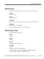
TRIGger
Force trigger event
TRIGger:MAIn
Set main trigger level to 50%; Query
returns main trigger settings
TRIGger:MAIn:EDGE?
Return edge trigger settings
TRIGger:MAIn:EDGE:COUPling
Set or query the edge trigger coupling
TRIGger:MAIn:EDGE:SLOpe
Set or query the edge trigger slope
TRIGger:MAIn:EDGE:SOUrce
Set or query the edge trigger source
TRIGger:MAIn:FREQuency?
(TDS1000, TDS2000, and TPS2000
only)
Return trigger frequency value
TRIGger:MAIn:HOLDOff?
Return trigger holdoff value
TRIGger:MAIn:HOLDOff:VALue
Set or query the trigger holdoff value
TRIGger:MAIn:LEVel
Set or query the trigger level
TRIGger:MAIn:MODe
Set or query the trigger mode
TRIGger:MAIn:PULse?
(TDS1000, TDS2000, and TPS2000
only)
Return pulse trigger settings
TRIGger:MAIn:PULse:SOUrce
(TDS1000, TDS2000, and TPS2000
only)
Set or query the pulse trigger source
TDS200/TDS1000/TDS2000/TPS2000 Series Programmer Manual
2- 35
Command Groups
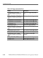
Table 2- 23: Trigger commands (Cont.)
2- 36
Header
Description
TRIGger:MAIn:PULse:WIDth?
(TDS1000, TDS2000, and TPS2000
only)
Return pulse trigger width parameters
TRIGger:MAIn:PULse:WIDth:POLarity
(TDS1000, TDS2000, and TPS2000
only)
Set or query the pulse trigger polarity
TRIGger:MAIn:PULse:WIDth:WHEN
Set or query the pulse trigger when
TRIGger:MAIn:PULse:WIDth:WIDth
Set or query the pulse trigger width
TRIGger:MAIn:TYPe
Set or query the main trigger type
TRIGger:MAIn:VIDeo?
Query video trigger parameters
TRIGger:MAIn:VIDeo:LINE
(TDS1000, TDS2000, and TPS2000
only)
Set or query the video trigger line
TRIGger:MAIn:VIDeo:POLarity
Set or query the video trigger polarity
TRIGger:MAIn:VIDeo:SOUrce
Set or query the video trigger source
TRIGger:MAIn:VIDeo:STANdard
(TDS1000, TDS2000, and TPS2000
only)
Set or query the video trigger
standard
TRIGger:MAIn:VIDeo:SYNC
Set or query the video trigger sync
TRIGger:STATE?
Return trigger system status
TDS200/TDS1000/TDS2000/TPS2000 Series Programmer Manual
Command Groups
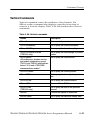
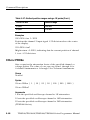
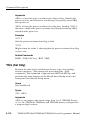
Vertical Commands
Vertical commands control the attributes of the channels. The
SELect:<wfm> command also displays a specified waveform or
removes it from the display. Table 2-- 24 lists and describes Vertical
commands.
Table 2- 24: Vertical commands
Header
Description
CH<x>?
Return vertical parameters
CH<x>:BANdwidth
Set or query the channel bandwidth
CH<x>:COUPling
Set or query the channel coupling
CH<x>:CURRENTPRObe
(TPS2000 only)
Set or query the scale settings for current
probes
CH<x>:INVert
(All oscilloscope, firmware version,
and module combinations except
TDS210 and TDS220 with firmware
below V 2.00 and a TDS2CMA
communications module.)
Set or query the channel invert
CH<x>:POSition
Set or query the channel position
CH<x>:PRObe
Set or query the channel probe parameters
CH<x>:SCAle
Set or query the channel volts/div
CH<x>:VOLts
Same as CH<x>:SCAle
CH<x>:YUNit
(TPS2000 only)
Set or query the units of the specified
channel
SELect?
Controls the display of waveforms
SELect:<wfm>
Set or query the waveform display state
TDS200/TDS1000/TDS2000/TPS2000 Series Programmer Manual
2- 37
Command Groups
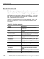
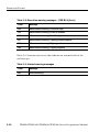
Waveform Commands
Waveform commands let you transfer waveform data points to and
from the oscilloscope. Waveform data points are a collection of
values that define a waveform. One data value usually represents one
data point in the waveform record. When working with peak-detect
waveforms, each data value is either the min or max of a min/max
pair. Before you can transfer waveform data, you must specify the
data format and waveform locations.
Table 2-- 25 lists and describes Waveform commands. Refer to the
text following this table for more information about waveform
commands.
Table 2- 25: Waveform commands
2- 38
Header
Description
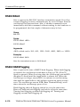
CURVe
Transfer waveform data to or from the
oscilloscope
DATa
Set or query the waveform data format and
location
DATa:DESTination
Set or query the destination for waveforms
sent to the oscilloscope
DATa:ENCdg
Set or query the waveform data encoding
method
DATa:SOUrce
Set or query the source of CURVe? data
DATa:STARt
Set or query the starting point in waveform
transfer
DATa:STOP
Set or query the ending point in waveform
transfer
DATa:TARget
Same as DATa:DESTination
DATa:WIDth
Set or query the byte width of waveform
points
WAVFrm?
Return waveform preamble and curve data
WFMPre?
Return waveform preamble
TDS200/TDS1000/TDS2000/TPS2000 Series Programmer Manual
Command Groups
Table 2- 25: Waveform commands (Cont.)
Header
Description
WFMPre:BIT_Nr
Set or query the preamble bit width of
waveform points
WFMPre:BN_Fmt
Set or query the preamble binary encoding
type
WFMPre:BYT_Nr
Set or query the preamble byte width of
waveform points
WFMPre:BYT_Or
Set or query the preamble byte order of
waveform points
WFMPre:ENCdg
Set or query the preamble encoding
method
WFMPre:NR_Pt
Query the number of points in the curve
transfer
WFMPre:PT_Fmt
Set or query the format of curve points
WFMPre:PT_Off
Query the trigger offset
WFMPre:WFId?
Query the waveform identifier
WFMPre:XINcr
Set or query the horizontal sampling
interval
WFMPre:XUNit
Set or query the horizontal units
WFMPre:XZEro
Set or query the time of first point in
waveform
WFMPre:YMUlt
Set or query the vertical scale factor
WFMPre:YOFf
Set or query the vertical offset
WFMPre:YUNit
Set or query the vertical units
WFMPre:YZEro?
(TDS200 Series with TDS2MM
measurement module, TDS1000,
TDS2000, TPS2000 only)
Set or query the waveform conversion
factor
WFMPre:<wfm>?
Return waveform formatting data
TDS200/TDS1000/TDS2000/TPS2000 Series Programmer Manual
2- 39
Command Groups
Table 2- 25: Waveform commands (Cont.)
Header
Description
WFMPre:<wfm>:NR_Pt?_Fmt
Return the number of points in the
transmitted waveform record
WFMPre:<wfm>:PT_Fmt
Set or query the format of curve points
WFMPre:<wfm>:PT_Off?
Query the trigger offset
WFMPre:<wfm>:WFId?
Query the waveform identifier
WFMPre:<wfm>:XINcr
Set or query the horizontal sampling
interval
WFMPre:<wfm>:XUNit
Set or query the horizontal units
WFMPre:<wfm>:XZEro
Set or query the time of first data point in
waveform
WFMPre:<wfm>:YMUlt
Set or query the vertical scale factor
WFMPre:<wfm>:YOFf
Set or query the vertical position
WFMPre:<wfm>:YUNit
Set or query the vertical units
WFMPre:<wfm>:YZEro?
(TDS200 Series with TDS2MM
measurement module, TDS1000,
TDS2000, and TPS2000 only)
Set or query the waveform conversion
factor
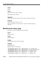
Waveform Data Formats
Internally, the oscilloscope uses one 8-bit data byte to represent each
waveform data point, regardless of the acquisition mode.
The DATa:WIDth command lets you specify the number of bytes per
data point when transferring data to and from an oscilloscope. This
provides compatibility with other digitizing oscilloscopes.
2- 40
TDS200/TDS1000/TDS2000/TPS2000 Series Programmer Manual
Command Groups
When DATa:WIDth is set to two:
H If sending data, the oscilloscope multiplies each point by 256; the
most significant byte then has meaningful data and the least
significant byte is 0
H If receiving data, the oscilloscope truncates the data (divides by
256) and saves the most significant byte
NOTE. The oscilloscopes uses these methods to handle waveforms
transmitted in ASCII or binary format.
The oscilloscope can transfer waveform data in either ASCII or
binary format. Use the DATa:ENCdg command to specify one of the
following formats:
H ASCII data is represented by signed integer values. The range of
values depends on the byte width specified. One-byte-wide data
ranges from –128 to 127. Two-byte-wide data ranges from
–32768 to 32767.
Each data value requires two to seven characters. This includes
one character for the minus sign if the value is negative, one to
five ASCII characters for the waveform value, and a comma to
separate data points.
An example of an ASCII waveform data string follows:
CURVE<space>–110,–109,–110,–110,–109,–107,–109,–107,
–106,–105,–103,–100,–97,–90,–84,–80
H Binary data can be represented by signed integer or positive
integer values. The range of the values depends on the byte width
specified.
Table 2-- 26 lists the ranges for one- and two-byte-wide data.
TDS200/TDS1000/TDS2000/TPS2000 Series Programmer Manual
2- 41
Command Groups
Table 2- 26: Binary data ranges
Byte width
Signed integer range
Positive integer range
1
–128 to 127
0 to 255
2
–32,768 to 32,767
0 to 65,535
The defined binary formats also specify the order in which the bytes
are transferred giving a total of four binary formats: RIBinary,
RPBinary, SRIbinary, and SRPbinary.
RIBinary is signed integer where the most significant byte is
transferred first, and RPBinary is positive integer where the most
significant byte is transferred first. SRIbinary and SRPbinary
correspond to RIBinary and RPBinary respectively but use a
swapped byte order where the least significant byte is transferred
first. The byte order is ignored when DATa:WIDth is set to 1.
Waveform Data Record
You can transfer multiple points for each waveform record. You can
transfer a portion of the waveform or you can transfer the entire
record. The DATa:STARt and DATa:STOP commands let you
specify the first and last data points of the waveform record.
When transferring data into the oscilloscope you must specify the
location of the first data point within the waveform record. For
example, when DATa:STARt is set to 1, data points will be stored
starting with the first point in the record, and when DATa:STARt is
set to 500, data will be stored starting at the 500th point in the record.
The oscilloscope ignores DATa:STOP when reading in data as the
oscilloscope will stop reading data when there is no more data to
read or when it has reached 2500 data points.
You must specify the first and last data points in the waveform
record when transferring data from the oscilloscope to an external
device. Setting DATa:STARt to 1 and DATa:STOP to 2500 always
sends the entire waveform, regardless of the acquisition mode.
2- 42
TDS200/TDS1000/TDS2000/TPS2000 Series Programmer Manual
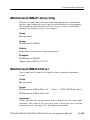
Command Groups
Waveform Data Locations and Memory Allocation
The DATa:SOUrce command specifies the location of the data when
transferring waveforms from the oscilloscope. You can transfer one
waveform at a time.
You can transfer only one waveform into the oscilloscope at a time.
Each waveform is stored in one of two stored waveform locations for
2-channel models or one of four stored waveform locations for
4-channel models. You specify the stored waveform location with
the DATa:DESTination command.
NOTE. The oscilloscope stores waveforms that are ≤2500 data points
long. The oscilloscope truncates waveforms longer than 2500 data
points.
Waveform Preamble
Each waveform that is transferred has an associated waveform
preamble that contains information such as the horizontal scale,
vertical scale, and other settings in place when the waveform was
created. Refer to the WFMPre commands on page 2-- 232 for more
information about the waveform preamble.
Scaling Waveform Data
Once you transfer the waveform data to the controller, you can
convert the data points into voltage values for analysis using
information from the waveform preamble.
TDS200/TDS1000/TDS2000/TPS2000 Series Programmer Manual
2- 43
Command Groups
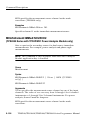
Transferring Waveform Data
Data transfer times depend on data format, data width, and the speed
of the controller. Refer to Programming Examples on page 4-- 1.
From the Oscilloscope. To transfer waveforms from the oscilloscope to
an external controller, follow these steps:
1. Use the DATa:SOUrce command to select the waveform source.
2. Use the DATa:ENCdg command to specify the waveform data
format.
3. Use the DATa:WIDth command to specify the number of bytes
per data point.
4. Use the DATa:STARt and DATa:STOP commands to specify the
portion of the waveform that you want to transfer.
5. Use the WFMPRe? command to transfer waveform preamble
information.
6. Use the CURVe? command to transfer waveform data.
To the Oscilloscope. To transfer waveform data to an oscilloscope
waveform storage location, follow these steps:
1. Use the DATa:DESTination command to specify the stored
waveform location.
2. Use the DATa:ENCdg command to specify the waveform data
format.
3. Use the DATa:WIDth command to specify the number of bytes
per data point.
4. Use the DATa:STARt command to specify the first data point in
the waveform record.
5. Use the WFMPRe command to transfer waveform preamble
information.
6. Use the CURVe? command to transfer waveform data.
2- 44
TDS200/TDS1000/TDS2000/TPS2000 Series Programmer Manual
Command Descriptions
Commands either set or query oscilloscope values. Some commands
both set and query, some only set, and some only query.
Manual Conventions
This manual uses the following conventions:
H No query form exists for commands identified as “Set Only”
H A question mark (?) appended to the command and “Query
Only” indicates query-only commands
H Fully spells out headers, mnemonics, and arguments with the
minimal spelling shown in upper case; for example, to use the
abbreviated form of the ACQuire:MODe command, just type
ACQ:MOD
H Syntax of some commands varies, depending on the model of
oscilloscope and extension module you are using; differences are
noted
NOTE. While Trigger View is active (when you push the TRIG VIEW
button on the front panel), the oscilloscope ignores the set form of
most commands. If you send a command at this time, the oscilloscope
generates execution error 221 (Settings conflict).
ACQuire? (Query Only)
Returns current acquisition settings.
Group
Acquisition
Syntax
ACQuire?
TDS200/TDS1000/TDS2000/TPS2000 Series Programmer Manual
2- 45
Command Descriptions
Returns
Returns current acquisition settings.
Examples
ACQuire?
Might return the following string for the current acquisition:
ACQUIRE:STOPAFTER RUNSTOP;STATE 1;MODE SAMPLE;NUMAVG 16
ACQuire:MODe
Sets or queries the oscilloscope acquisition mode. This affects all
live waveforms and is equivalent to setting the Mode option in the
Acquire menu.
Waveforms are the displayed data point values taken from
acquisition intervals. Each acquisition interval represents a time
duration that is determined by the horizontal scale (time per
division).
The oscilloscope sampling system can operate at a rate greater than
that indicated by the horizontal scale. Therefore, an acquisition
interval can include more than one sample.
The acquisition mode, which you set using this ACQuire:MODe
command, determines how the final value of the acquisition interval
is generated from the many data samples.
Group
Acquisition
Syntax
ACQuire:MODe { SAMple | PEAKdetect | AVErage }
ACQuire:MODe?
Arguments
SAMple specifies that the displayed data point value is the first
sampled value that was taken during the acquisition interval. The
waveform data has 8 bits of precision in all acquisition modes. You
2- 46
TDS200/TDS1000/TDS2000/TPS2000 Series Programmer Manual
Command Descriptions
can request 16 bit data with a CURVe? query, but the lower-order
8 bits of data will be zero. SAMple is the default mode.
PEAKdetect specifies the display of the high-low range of the
samples taken from a single waveform acquisition. The oscilloscope
displays the high-low range as a vertical range that extends from the
highest to the lowest value sampled during the acquisition interval.
PEAKdetect mode can reveal the presence of aliasing.
AVErage specifies averaging mode, where the resulting waveform
shows an average of SAMple data points from several separate
waveform acquisitions. The number of waveform acquisitions that
go into making up the average waveform is set or queried using the
ACQuire:NUMAVg command.
Examples
ACQuire:MODe PEAKdetect
Displays a vertical area representing the range of the highest to
lowest value of the acquired signal.
ACQuire:MODe?
Might return SAMPLE.
Related Commands
WFMPre:PT_Fmt
ACQuire:NUMACq? (Query Only)
Indicates the number of acquisitions that have taken place since
starting oscilloscope acquisition. The maximum number of
acquisitions that can be counted is 231-1. This value is reset to zero
when you change most Acquisition, Horizontal, Vertical, or Trigger
arguments that affect the waveform except for the following:
H Changing the trigger level or trigger holdoff when in Sample or
Peak Detect mode does not reset the value
TDS200/TDS1000/TDS2000/TPS2000 Series Programmer Manual
2- 47
Command Descriptions
NOTE. Any change made when in Average mode aborts the
acquisition and resets ACQuire:NUMACq to zero.
H TDS200 Series: changing the vertical position does not reset the
value
H TDS1000, TDS2000, and TPS2000 Series: if the Trigger mode is
set to Auto, and the Horizontal Scale is 10 ms/div or slower,
changing the vertical position does not reset the value
NOTE. In Scan mode, ACQuire:NUMACq? always returns zero.
Group
Acquisition
Syntax
ACQuire:NUMACq?
Returns
<NR1>
Examples
ACQuire:NUMACq?
Might return 350, indicating that 350 acquisitions took place since
an ACQuire:STATE RUN command was executed.
ACQuire:NUMAVg
Sets the number of oscilloscope waveform acquisitions that make up
an averaged waveform. This command is equivalent to setting the
Averages option in the Acquire menu.
Group
Acquisition
2- 48
TDS200/TDS1000/TDS2000/TPS2000 Series Programmer Manual
Command Descriptions
Syntax
ACQuire:NUMAVg <NR1>
ACQuire:NUMAVg?
Arguments
<NR1> is the number of waveform acquisitions. Correct values are 4,
16, 64, and 128.
Examples
ACQuire:NUMAVg 16
This specifies that an averaged waveform will show the result of
combining 16 separately acquired waveforms.
ACQuire:NUMAVg?
Might return 64, indicating that there are 64 acquisitions specified
for averaging.
ACQuire:STATE
Starts or stops oscilloscope acquisitions. This command is the
equivalent of pressing the front-panel RUN/STOP button. If
ACQuire:STOPAfter is set to SEQuence, other signal events may
also stop acquisition.
NOTE. The best way to determine when a single sequence acquisition
is complete is to use *OPC? rather than ACQuire:STATE?. For more
information on the *OPC? command, refer to page 2-- 165.
Group
Acquisition
Syntax
ACQuire:STATE { OFF | ON | RUN | STOP | <NR1> }
ACQuire:STATE?
TDS200/TDS1000/TDS2000/TPS2000 Series Programmer Manual
2- 49
Command Descriptions
Arguments
OFF | STOP | <NR1> = 0 stops acquisitions.
ON | RUN | <NR1> ≠ 0 starts acquisition and display of waveforms. If
the command was issued in the middle of an acquisition sequence
(for instance averaging), RUN restarts the sequence, discarding any
data accumulated before the STOP. It also resets the number of
acquisitions.
Examples
ACQuire:STATE RUN
Starts acquisition of waveform data and resets the number of
acquisitions count (NUMACq) to zero.
ACQuire:STATE?
Returns 0 or 1, depending on whether or not the acquisition system is
running.
Related Commands
*OPC?
ACQuire:STOPAfter
Tells the oscilloscope when to stop taking acquisitions.
Group
Acquisition
Syntax
ACQuire:STOPAfter { RUNSTop | SEQuence}
ACQuire:STOPAfter?
Arguments
RUNSTop specifies that the run and stop states should be determined
by pressing the front-panel RUN/STOP button or issuing the
ACQuire:STATE command.
2- 50
TDS200/TDS1000/TDS2000/TPS2000 Series Programmer Manual
Command Descriptions
SEQuence specifies “single sequence” operation, where the
oscilloscope stops after it has acquired enough waveforms to satisfy
the conditions of the acquisition mode. For example, if the
acquisition mode is set to sample, the oscilloscope stops after
digitizing a waveform from a single trigger event. However, if the
acquisition mode is set to average 64 waveforms, then the oscilloscope stops only after acquiring all 64 waveforms.
The ACQuire:STATE command and the front-panel RUN/STOP
button also stop acquisitions when the oscilloscope is in single
sequence mode.
Examples
ACQuire:STOPAfter RUNSTop
Sets the oscilloscope to stop the acquisition when you press the
front-panel RUN/STOP button.
ACQuire:STOPAfter?
Might return SEQUENCE.
ALLEv? (Query Only)
Causes the oscilloscope to return all events and their messages, and
removes the returned events from the Event Queue. The messages
are separated by commas. Use the *ESR? query to enable the events
to be returned. For a complete discussion of how to use these
registers, refer to page 3-- 1. This command is similar to repeatedly
sending *EVMsg? queries to the oscilloscope.
Group
Status and error
Syntax
ALLEv?
Returns
The event code and message in the following format:
TDS200/TDS1000/TDS2000/TPS2000 Series Programmer Manual
2- 51
Command Descriptions
<Event Code><Comma><QString>[<Comma><Event
Code><Comma><QString>...]
<QString>::= <Message>;[<Command>]
<Command> is the command that caused the error and may be
returned when a command error is detected by the oscilloscope. As
much of the command is returned as possible without exceeding the
60 character limit of the <Message> and <Command> strings
combined. The command string is right-justified.
Examples
ALLEv?
Might return the following string:
:ALLEV 2225,“Measurement error, No waveform to measure;
”,420,“Query UNTERMINATED; ”
Related Commands
*CLS, DESE, *ESE, *ESR?, EVENT?, EVMsg?, EVQty?, *SRE,
*STB?
AUTORange?
(TPS2000 Only)
Returns current AUTORange settings.
Group
Power Measurement
Syntax
AUTORange?
Examples
AUTORange?
Might return :AUTORANGE:SETTINGS BOTH;STATE 1, indicating that
Autorange is active and adjusting both the horizontal and vertical
settings.
2- 52
TDS200/TDS1000/TDS2000/TPS2000 Series Programmer Manual
Command Descriptions
AUTORange:STATE
(TPS2000 Only)
Toggles Autorange off and on.
Group
Miscellaneous
Syntax
AUTORange:STATE { OFF | ON | <NR1> }
AUTORange:STATE?
Arguments
OFF deactivates the Autorange feature.
ON activates the Autorange feature.
<NR1> = 0 deactivates the Autorange feature.
<NR1> ≠ 0 activates the Autorange feature.
Examples
AUTORANGE:STATE ON
Starts the Autorange function.
AUTORANGE:STATE?
Returns 0 or 1, depending on whether or not the Autorange function
is on.
Related Commands
AUTORange:SETTings
AUTORange:SETTings
(TPS2000 Only)
Controls the parameters that the Autorange function can adjust. It is
equivalent to the option buttons in the Autorange menu.
TDS200/TDS1000/TDS2000/TPS2000 Series Programmer Manual
2- 53
Command Descriptions
Group
Miscellaneous
Syntax
AUTORange:SETTings { HORizontal | VERTical | BOTH }
AUTORange:SETTings?
Arguments
HORizontal allows Autorange to adjust the horizontal, but not
vertical, settings.
VERTical allows Autorange to adjust the vertical, but not horizontal, settings.
BOTH allows Autorange to adjust both the horizontal and vertical
settings.
Examples
AUTORANGE:SETTINGS VERTICAL
Turns on the Autorange vertical settings.
AUTORANGE:SETTINGS?
Might return VERTICAL, indicating that Autorange will only adjust
the vertical settings.
Related Commands
AUTORange:STATE
AUTOSet (Set Only)
Causes the oscilloscope to adjust its vertical, horizontal, and trigger
controls to display a stable waveform. This command is equivalent
to pushing the front-panel AUTOSET button.
For a detailed description of the Autoset function, refer to the user
manual for your oscilloscope.
Group
Miscellaneous
2- 54
TDS200/TDS1000/TDS2000/TPS2000 Series Programmer Manual
Command Descriptions
Syntax
AUTOSet EXECute
Arguments
EXECute invokes Autoset.
AUTOSet:SIGNAL? (Query Only)
(TDS1000, TDS2000, and TPS2000 only)
Returns the type of signal discovered by the most recent execution of
Autoset.
Group
Miscellaneous
Syntax
AUTOSet:SIGNAL?
Returns
Might return { LEVEL | SINE | SQUARE | VIDPAL | VIDNTSC |
OTHER | NONe }
LEVEL if the oscilloscope discovered a DC level.
SINE if the oscilloscope discovered a sine-like waveform.
SQUARE if the oscilloscope discovered a square-like waveform.
VIDPAL if the oscilloscope discovered a PAL or SECAM standard
video signal.
VIDNTSC if the oscilloscope discovered an NTSC standard video
signal.
OTHER if the oscilloscope was unable to classify the signal.
NONE if the AUTOSET menu is not displayed.
TDS200/TDS1000/TDS2000/TPS2000 Series Programmer Manual
2- 55
Command Descriptions
AUTOSet:VIEW
(TDS1000, TDS2000, and TPS2000 Only)
If the current menu is not the Autoset menu, or if the view is not
valid for the detected waveform, the set command causes the
oscilloscope to generate error 221 (Settings conflict).
Group
Miscellaneous
Syntax
AUTOSet:VIEW { MULTICYcle | SINGLECYcle | FFT |
RISINGedge | FALLINGedge | FIELD | ODD | EVEN | LINE |
LINENum | DCLIne | DEFault | NONE }
Arguments
MULTICYcle displays a sine or square wave of several cycles. Default
for sine-like and square-like signals.
SINGLECYcle displays a sine or square wave of approximately one
cycle.
FFT displays the FFT of a sine wave.
RISING displays the rising edge of a square wave.
FALLING displays the falling edge of a square wave.
FIELD displays a video signal synchronized on all fields. This is the
default for video signals.
ODD displays a video signal synchronized on odd fields.
EVEN displays a video signal synchronized on even fields.
LINE displays a video signal synchronized on all lines.
LINENum displays a video signal synchronized on the specified line
number.
DCLIne returns a query response when the oscilloscope finds a DC
level.
2- 56
TDS200/TDS1000/TDS2000/TPS2000 Series Programmer Manual
Command Descriptions
DEFault returns a query response when the oscilloscope cannot
determine the signal type.
NONE returns a query response when the AUTOSET menu is not
displayed. Set is ignored.
Examples
AUTOSet:VIEW EVEN
The oscilloscope will display video signals synchronized on even
fields when operated in autoset mode.
BUSY? (Query Only)
Returns the status of the oscilloscope. This command allows you to
synchronize the operation of the oscilloscope with your application
program. Refer to Synchronization Methods on page 3-- 10 for more
information.
Group
Status and error
Syntax
BUSY?
Returns
0 when the oscilloscope is not busy processing any of the commands
listed in Table 2-- 29 (*OPC) on page 2-- 166.
1 when the oscilloscope is busy processing one of the commands
listed in Table 2-- 29 (*OPC) on page 2-- 166.
Examples
BUSY?
Might return 1, indicating that the oscilloscope is busy.
Related Commands
*OPC, *WAI
TDS200/TDS1000/TDS2000/TPS2000 Series Programmer Manual
2- 57
Command Descriptions
*CAL? (Query Only)
Performs an internal self-calibration and returns its status. This is
equivalent to selecting the Do Self Cal option in the Utility menu.
Although *CAL? is a query command, it does perform an action.
NOTE. The self-calibration can take several minutes to complete.
During this time, the oscilloscope does not execute any commands.
Disconnect all signals from the oscilloscope before performing an
internal self-calibration.
Group
Calibration and Diagnostic
Syntax
*CAL?
Returns
0 indicates that the self-calibration completed without any errors
detected.
Any value other than zero indicates that the self-calibration did not
complete successfully or completed with errors.
Examples
*CAL?
Performs a self-calibration and might return 0 to indicate that it
completed successfully.
Related Commands
CALibrate:INTERNAL
2- 58
TDS200/TDS1000/TDS2000/TPS2000 Series Programmer Manual
Command Descriptions
CALibrate:ABOrt (Set Only)
NOTE. You should only use this command in a qualified service
environment. For more information about the factory calibration
sequence, refer to the service manual for your oscilloscope.
Aborts the factory calibration process. When you abort the factory
calibration, the oscilloscope restores the calibration settings to the
previous factory calibration constants stored in non-volatile memory.
Group
Calibration and Diagnostic
Syntax
CALibrate:ABOrt
Examples
CALibrate:ABOrt
Stops the in-process factory calibration procedure.
CALibrate:CONTINUE (Set Only)
NOTE. You should only use this command in a qualified service
environment. For more information about the factory calibration
sequence, refer to the service manual for your oscilloscope.
Performs the next step in the factory calibration operation.
Group
Calibration and Diagnostic
Syntax
CALibrate:CONTINUE
TDS200/TDS1000/TDS2000/TPS2000 Series Programmer Manual
2- 59
Command Descriptions
Examples
CALibrate:CONTINUE
Performs the next step in the factory calibration operation.
CALibrate:FACtory (Set Only)
NOTE. You should only use this command in a qualified service
environment. For more information about the factory calibration
sequence, refer to the service manual for your oscilloscope.
Starts the oscilloscope’s internal factory calibration operation. The
calibration operation consists of a sequence of steps. You send the
CALibrate:CONTINUE command to advance to the next calibration
step. The calibration program automatically sets up the oscilloscope
for each calibration step. Use the CALibrate:ABOrt command to
abort the factory calibration.
You can only send synchronization commands or queries (such as
*OPC, OPC?, *WAI, BUSY?) while doing a factory calibration.
Group
Calibration and Diagnostic
Syntax
CALibrate:FACtory
Examples
CALibrate:FACtory
Starts the factory calibration process.
CALibrate:INTERNAL (Set Only)
Performs an internal self-calibration but does not return any status.
This is equivalent to selecting the Do Self Cal option in the Utility
menu.
2- 60
TDS200/TDS1000/TDS2000/TPS2000 Series Programmer Manual
Command Descriptions
NOTE. The self-calibration can take several minutes to complete.
During this time, the oscilloscope does not execute any commands.
Disconnect all signals from the oscilloscope before performing an
internal self-calibration.
Syntax
CALibrate:INTERNAL
Examples
CALibrate:INTERNAL
Performs an internal self-calibration.
Related Commands
*CAL?
CALibrate:STATUS? (Query Only)
Returns the status of the last calibration operation performed (either
self- or factory-calibration) since power up.
Group
Calibration and Diagnostic
Syntax
CALibrate:STATUS?
Returns
PASS indicates that the oscilloscope completed the last calibration
operation without detecting any errors.
FAIL indicates that the oscilloscope detected errors during the last
calibration operation, or that no calibration operations have been
performed since power up.
TDS200/TDS1000/TDS2000/TPS2000 Series Programmer Manual
2- 61
Command Descriptions
Examples
CALibrate:STATUS?
Might return CALIBRATE:STATUS FAIL, if the oscilloscope failed the
last calibration operation.
CH<x>? (Query Only)
Returns the current oscilloscope vertical settings. The value of <x>
can vary from 1 through 4 for 4-channel instruments or 1 through 2
for 2-channel instruments.
Because CH<x>:SCAle and CH<x>:VOLts are identical, only
CH<x>:SCAle is returned.
Group
Vertical
Syntax
CH<x>?
Returns
Oscilloscope vertical settings.
Examples
CH1?
Might return the following string for channel 1:
CH1:SCALE 1.0E0;POSITION 0.0E0; COUPLING DC;BANDWIDTH
OFF;PROBE 1.0E0
Related Commands
SELect:CH<x>
CH<x>:BANdwidth
Sets or queries the bandwidth setting of the specified oscilloscope
channel. The value of <x> can vary from 1 through 4 for 4-channel
instruments or 1 through 2 for 2-channel instruments.
2- 62
TDS200/TDS1000/TDS2000/TPS2000 Series Programmer Manual
Command Descriptions
This command is equivalent to setting the BW Limit option in the
Vertical menu.
Group
Vertical
Syntax
CH<x>:BANdwidth { ON | OFF }
CH<x>:BANdwidth?
Arguments
ON sets the channel bandwidth to 20 MHz.
OFF sets the channel bandwidth to the full bandwidth of the
oscilloscope.
In most acquisition modes, full bandwidth is 60 MHz, 100 MHz, or
200 MHz (depending on the oscilloscope model). There are
exceptions.
TDS1000, TDS2000, TPS2000 Series
At vertical scales from 2.00 to 4.99 mV/div (sensitivity at the BNC;
that is, after the probe factor is removed), the full bandwidth is
20 MHz.
TDS200 Series
At vertical scales of 5 mV/div or less (sensitivity at the BNC; that is,
after the probe factor is removed), the full bandwidth is 20 MHz.
When the acquisition mode is Peak Detect, and the vertical scale at
the BNC is 10 mV/div or less, the full bandwidth is also 20 MHz.
Examples
CH2:BANDWIDth ON
Sets the bandwidth of channel 2 to 20 MHz.
CH1:BANDWIDth?
Might return OFF. This indicates there is no bandwidth limiting on
channel 1.
TDS200/TDS1000/TDS2000/TPS2000 Series Programmer Manual
2- 63
Command Descriptions
CH<x>:COUPling
Sets or queries the input attenuator coupling setting of the specified
oscilloscope channel. The value of <x> can vary from 1 through 4
for 4-channel instruments or 1 through 2 for 2-channel instruments.
This command is equivalent to setting the Coupling option in the
Vertical menu.
Group
Vertical
Syntax
CH<x>:COUPling { AC | DC | GND }
CH<x>:COUPling?
Arguments
AC sets the specified oscilloscope channel to AC coupling.
DC sets the specified oscilloscope channel to DC coupling.
GND sets the specified oscilloscope channel to ground. Only a flat
ground-level waveform is displayed.
Examples
CH1:COUPlING AC
This establishes AC coupling on channel 1.
CH2:COUPlING?
Might return DC. Indicating that channel 2 is set to DC coupling.
CH<x>:CURRENTPRObe
(TPS2000 Only)
Sets or queries the scale factor of the specified channel for current
probes. The value of <x> can vary from 1 through 4 for 4-channel
instruments or 1 through 2 for 2-channel instruments.
2- 64
TDS200/TDS1000/TDS2000/TPS2000 Series Programmer Manual
Command Descriptions
You can issue this command when CH<x>:YUNit <QString> is set
to V. However, this command only affects the readouts when
CH<x>:YUNit <QString> is set to A.
Group
Vertical
Syntax
CH<x>:CURRENTPRObe { 0.2 | 1 | 2 | 5 | 10 | 50 | 100 |
1000 }
CH<x>:CURRENTPRObe?
Arguments
0.2 sets the specified oscilloscope channel to 0.2X attenuation.
1 sets the specified oscilloscope channel to 1X attenuation.
2 sets the specified oscilloscope channel to 2X attenuation.
5 sets the specified oscilloscope channel to 5X attenuation.
10 sets the specified oscilloscope channel to 10X attenuation.
50 sets the specified oscilloscope channel to 50X attenuation.
100 sets the specified oscilloscope channel to 100X attenuation.
1000 sets the specified oscilloscope channel to 1000X attenuation.
Returns
<NR1>
Examples
CH2:CURRENTPRObe 1000
This sets channel 2 to 1000X attenuation.
CH1:CURRENTPRObe?
Might return 10.
TDS200/TDS1000/TDS2000/TPS2000 Series Programmer Manual
2- 65
Command Descriptions
CH<x>:INVert
NOTE. You can NOT use this command with a TDS210 or TDS220
oscilloscope with firmware below V 2.00 and a TDS2CMA
(or TDS2CM) communications module.
Sets or queries the inversion state of the specified oscilloscope
channel. The value of <x> can vary from 1 through 4 for 4-channel
instruments or 1 through 2 for 2-channel instruments.
This command is equivalent to setting the Invert option in the
Vertical channel menus.
Group
Vertical
Syntax
CH<x>:INVert { ON | OFF }
CH<x>:INVert?
Arguments
ON inverts the specified oscilloscope channel.
OFF sets the specified oscilloscope channel to non-inverted.
Examples
CH1:INVert ON
Inverts the signal on channel 1.
CH2:INVert?
Might return OFF, indicating that channel 2 is not inverted.
2- 66
TDS200/TDS1000/TDS2000/TPS2000 Series Programmer Manual
Command Descriptions
CH<x>:POSition
Sets or queries the vertical position of the specified oscilloscope
channel. The value of <x> can vary from 1 through 4 for 4-channel
instruments or 1 through 2 for 2-channel instruments.
The position voltage value is applied to the signal before digitization. This command is equivalent to adjusting the front-panel
VERTICAL POSITION knob.
Group
Vertical
Syntax
CH<x>:POSition <NR3>
CH<x>:POSition?
Arguments
<NR3> is the position in divisions from the center graticule.
Table 2-- 27 lists the vertical position ranges using a 1X probe.
Table 2- 27: Vertical position ranges using a 1X probe
CH<x>:SCAle
Position range
2 mV/div
±1000 divs
5 mV/div
±400 divs
10 mV/div
±200 divs
20 mV/div
±100 divs
50 mV/div
±40 divs
100 mV/div
±20 divs
200 mV/div
±10 divs
500 mV/div
±100 divs
1 V/div
±50 divs
TDS200/TDS1000/TDS2000/TPS2000 Series Programmer Manual
2- 67
Command Descriptions
Table 2- 27: Vertical position ranges using a 1X probe (Cont.)
CH<x>:SCAle
Position range
2 V/div
±25 divs
5 V/div
±10 divs
Examples
CH2:POSition 1.32E0
Positions the channel 2 input signal 1.32 divisions above the center
of the display.
CH1:POSition?
Might return –1.32E0, indicating that the current position of channel
1 is at –1.32 divisions.
CH<x>:PRObe
Sets or queries the attenuation factor of the specified channel or
voltage probes. The value of <x> can vary from 1 through 4 for
4-channel instruments or 1 through 2 for 2-channel instruments.
Group
Vertical
Syntax
CH<x>:PRObe { 1 | 10 | 20 | 50 | 100 | 500 | 1000 }
CH<x>:PRObe?
Arguments
1 sets the specified oscilloscope channel to 1X attenuation.
10 sets the specified oscilloscope channel to 10X attenuation.
20 sets the specified oscilloscope channel to 20X attenuation.
(TPS2000 Series)
2- 68
TDS200/TDS1000/TDS2000/TPS2000 Series Programmer Manual
Command Descriptions
50 sets the specified oscilloscope channel to 50X attenuation.
(TPS2000 Series)
100 sets the specified oscilloscope channel to 100X attenuation.
500 sets the specified oscilloscope channel to 500X attenuation.
(TPS2000 Series)
1000 sets the specified oscilloscope channel to 1000X attenuation.
Returns
<NR1>
Examples
CH2:PRObe 1000
Sets channel 2 to 1000X attenuation.
CH1:PRObe?
Might return CH1:PROBE 10
CH<x>:SCAle
Sets or queries the vertical gain of the specified oscilloscope
channel. The value of <x> can vary from 1 through 4 for 4-channel
instruments or 1 through 2 for 2-channel instruments.
This command is equivalent to adjusting the front-panel VOLTS/
DIV knob.
Group
Vertical
Syntax
CH<x>:SCAle <NR3>
CH<x>:SCAle?
TDS200/TDS1000/TDS2000/TPS2000 Series Programmer Manual
2- 69
Command Descriptions
Arguments
<NR3> is the gain, in volts or amps per division. For example, the
voltage range is 5 V/div to 2 mV/div when using a 1X voltage probe.
Examples
CH1:SCAle 100E–3
Sets the channel 1 gain to 100 mV/div.
CH2:SCAle?
Might return 1.0E0, indicating that the current V/div setting of
channel 2 is 1 V/div.
Related Commands
CH1:VOLts
CH<x>:VOLts
Sets or queries the vertical gain of the specified channel. The value
of <x> can vary from 1 through 4 for 4-channel instruments or 1
through 2 for 2-channel instruments.
This command is identical to the CH<x>:SCAle command and is
included for compatibility purposes. Only CH<x>:SCAle is returned
in response to a CH<x>? query.
CH<x>:YUNit
(TPS2000 Only)
Sets or queries the units of the specified channel. The value of <x>
can vary from 1 through 4 for 4-channel instruments or 1 through 2
for 2-channel instruments.
Group
Vertical
Syntax
CH<x>:YUNit <QString>
2- 70
TDS200/TDS1000/TDS2000/TPS2000 Series Programmer Manual
Command Descriptions
CH<x>:YUNit?
Arguments
<QString> is either “V” for volts or “A” for amps. This is equivalent
to setting the probe to Voltage or Current in the probe front-panel
menu. This command is case insensitive.
Examples
CH2:YUNIT?
Might return CH2:YUNIT “V”, indicating that the channel 2 units are
volts.
*CLS (Set Only)
The *CLS command clears the following oscilloscope status data
structures:
H The Event Queue
H The Standard Event Status Register (SESR)
H The Status Byte Register (except the MAV bit described on
page 2-- 71)
If the *CLS command immediately follows an <EOI>, the Output
Queue and MAV bit (Status Byte Register bit 4) are also cleared.
MAV indicates information is in the output queue. The device clear
(DCL) GPIB control message will clear the output queue and also
MAV.
*CLS does not clear the output queue or MAV. *CLS can suppress a
service request that is to be generated by an *OPC command. This
will happen if a hard copy output or single sequence acquisition
operation is still being processed when the *CLS command is
executed.
Refer to Registers on page 3-- 1 for more information.
Group
Status and Error
TDS200/TDS1000/TDS2000/TPS2000 Series Programmer Manual
2- 71
Command Descriptions
Syntax
*CLS
Related Commands
DESE, *ESE, *ESR?, EVENT?, EVMsg?, *SRE, *STB?
CURSor? (Query Only)
Returns current cursor settings.
Group
Cursor
Syntax
CURSor?
Returns
Oscilloscope cursor settings.
Examples
CURSor?
Might return the following string as the current cursor settings:
CURSOR:FUNCTION VBARS;SELECT:SOURCE CH1; :CURSOR:VBARS:UNITS SECONDS;POSITION1 0.0E0;POSITION2
4.48E–3;:CURSOR:HBARS:UNITS VOLTS;POSITION1 0.0E0;POSITION2 5.0E–1.
CURSor:FUNCtion
Selects and displays the oscilloscope cursor type. Cursors are
attached to the waveform selected by CURSor:SELect:SOUrce. This
command is equivalent to setting the Type option in the Cursor
menu. Setting the function to anything other than OFF causes the
Cursor menu to be displayed.
2- 72
TDS200/TDS1000/TDS2000/TPS2000 Series Programmer Manual
Command Descriptions
NOTE. Setting the display format to XY removes the cursors. Sending
the CURSor:FUNCtion command when the display format is XY
causes the oscilloscope to generate event 221 (Settings conflict) and
leaves the display in XY format.
Group
Cursor
Syntax
CURSor:FUNCtion { HBArs | OFF | VBArs }
CURSor:FUNCtion?
Arguments
HBArs specifies horizontal bar cursors that measure the vertical units
in volts, amps, divisions, or decibels.
OFF removes cursors from the display.
VBArs specifies vertical bar cursors that measure time or frequency.
Examples
CURSor:FUNCtion VBArs
Selects vertical bar type cursors.
CURSor:HBArs? (Query Only)
Returns the current settings for the oscilloscope horizontal bar
cursors.
Group
Cursor
Syntax
CURSor:HBArs?
TDS200/TDS1000/TDS2000/TPS2000 Series Programmer Manual
2- 73
Command Descriptions
Returns
Current horizontal bar cursor settings.
Examples
CURSor:HBArs?
Might return the following string:
CURSOR:HBARS:UNITS VOLTS;POSITION1 0.0E0; POSITION2
0.0E0.
CURSor:HBArs:DELTa? (Query Only)
Returns the difference (in vertical units) between the two horizontal
bar cursors in the oscilloscope display.
NOTE. If Trigger View is active, this query returns 9.9E37 and
generates event 221 (Settings conflict).
Group
Cursor
Syntax
CURSor:HBArs:DELTa?
Returns
<NR3>
Examples
CURSor:HBArs:DELTa?
Might return 5.08E0 for the difference between the two cursors.
CURSor:HBArs:POSITION<x>
Positions a horizontal bar cursor. The value of <x> can vary from 1
through 2.
2- 74
TDS200/TDS1000/TDS2000/TPS2000 Series Programmer Manual
Command Descriptions
NOTE. If Trigger View is active, the query form returns 9.9E37 and
generates event 221 (Settings conflict).
Group
Cursor
Syntax
CURSor:HBArs:POSITION<x> <NR3>
CURSor:HBArs:POSITION<x>?
Arguments
<NR3> specifies the horizontal bar cursor position, relative to ground
(in volts when the units are volts and amps when the units are amps),
relative to the center of the screen (in divs when units are divisions),
or relative to 1 V RMS (in decibels when the source is an FFT math
waveform), for the waveform specified by the CURSor:SELect:SOUrce command.
The cursor position is limited to the graticule whenever an attempt is
made to move it outside the graticule.
NOTE. The source always determines the measurement units.
Examples
CURSor:HBArs:POSITION1 25.0E–3
Positions one of the horizontal cursors at 25.0 mV (assuming the
vertical units are volts).
CURSor:HBArs:POSITION2?
Might return –6.40E–2, indicating that the second horizontal bar
cursor is at –64.0 mV (assuming the vertical units are volts).
TDS200/TDS1000/TDS2000/TPS2000 Series Programmer Manual
2- 75
Command Descriptions
CURSor:HBArs:UNIts? (Query Only)
Returns the vertical scale units for the selected cursor source
waveform.
Group
Cursor
Syntax
CURSor:HBArs:UNIts?
Returns
VOLts indicates volts from ground as the unit of measure.
DIVs indicates divisions as the unit of measure, with center of screen
as 0 divisions and bottom of screen as –4 divisions.
DECIBELS indicates decibels as the unit of measure, relative to a
1 Vrms sine wave. (FFT only)
UNKNOWN indicates that Trigger View is active. This also generates
event message 221. (Settings conflict)
AMPS indicates amps as the unit of measure. (TPS2000 Series only)
VOLTSSQUARED indicates volts squared (V*V) as the unit of measure.
(TPS2000 Series only)
AMPSSQUARED indicates amps squared (A*A) as the unit of measure.
(TPS2000 Series only)
VOLTSAMPS indicates voltage times current (V*A) as the unit of
measure. (TPS2000 Series only)
NOTE. Unknown units are represented by ”?” in the oscilloscope
readouts.
2- 76
TDS200/TDS1000/TDS2000/TPS2000 Series Programmer Manual
Command Descriptions
Examples
CURSor:HBArs:UNIts?
Might return CURSOR:HBARS:UNITS VOLTS.
CURSor:SELect:SOUrce
Sets or queries the waveform that is the source of the vertical and
horizontal scale factors used in determining cursor values. This
command is equivalent to setting the Source option in the Cursor
menu.
Group
Cursor
Syntax
CURSor:SELect:SOUrce <wfm>
CURSor:SELect:SOUrce?
Arguments
<wfm> specifies the waveform data source on which cursor
measurements will be taken.
Examples
CURSor:SELect:SOUrce CH1
Selects channel 1.
CURSor:SELect:SOUrce?
Might return MATH.
CURSor:VBArs? (Query Only)
Returns the current vertical bar cursor horizontal position and units
settings.
Group
Cursor
TDS200/TDS1000/TDS2000/TPS2000 Series Programmer Manual
2- 77
Command Descriptions
Syntax
CURSor:VBArs?
Examples
CURSor:VBArs?
Might return CURSOR:VBARS:UNITS SECONDS;
POSITION1 1.00E–6;POSITION2 9.00E–6
CURSor:VBArs:DELTa? (Query Only)
Returns the time or frequency difference between the two vertical
bar cursors. The units (seconds or Hertz) are specified by the
CURSor:VBArs:UNIts command. If the cursor source is an FFT
math waveform, CURSor:VBArs:DELTa is always in Hertz,
regardless of the value set by CURSor:VBArs:UNIts.
NOTE. If Trigger View is active, this query returns 9.9E37 and
generates event 221 (Settings conflict).
Group
Cursor
Syntax
CURSor:VBArs:DELTa?
Returns
<NR3>
Examples
CURSor:VBArs:DELTa?
Might return 8.92E–1, indicating that the time difference between
the vertical bar cursors is 0.892 seconds.
2- 78
TDS200/TDS1000/TDS2000/TPS2000 Series Programmer Manual
Command Descriptions
CURSor:VBArs:HDELTa? (Query Only)
(TPS2000 only)
Returns the time or frequency difference between the two vertical
bar cursors. The units (seconds or Hertz) are specified by the
CURSor:VBArs:UNIts command. If the cursor source is an FFT
math waveform, CURSor:VBArs:DELTa is always in Hertz,
regardless of the value set by CURSor:VBArs:UNIts.
The command is identical to the CURSor:VBArs:DELTa? query. It is
included for compatibility with the TDS3000 Series.
NOTE. If Trigger View is active, this query returns 9.9E37 and
generates event 221 (Settings conflict).
Group
Cursor
Syntax
CURSor:VBArs:HDELTa?
Returns
<NR3>
Examples
CURSor:VBArs:HDELTa?
Might return 8.92E–1, indicating that the time difference between
the vertical bar cursors is 0.892 seconds.
CURSor:VBArs:HPOS<x>? (Query Only)
Returns the waveform amplitude at the specified cursor position. The
units are specified by the CURSor:HBArs:UNIts query.
TDS200/TDS1000/TDS2000/TPS2000 Series Programmer Manual
2- 79
Command Descriptions
Group
Cursor
Syntax
CURSor:VBArs:HPOS<x>?
Arguments
<x> specifies the cursor. Valid values are 1 and 2.
Returns
<NR3> indicates the amplitude value at the selected position.
Examples
CURSOR:VBARS:HPOS1?
Might return 1.37, indicating the value of one vertical bar tic.
Related Commands
CURSor:HBArs:UNIts
CURSor:VBArs:POSITION<x>
Positions a vertical bar cursor. The unit is specified by the
CURSor:VBArs:UNIts command, and can be in units of seconds or
frequency (Hertz). If the cursor source is an FFT math waveform,
CURSor:VBArs:POSITION is always in Hertz, regardless of the
value set by CURSor:VBArs:UNIts.
NOTE. If Trigger View is active, the query form returns 9.9E37 and
generates event 221 (Settings conflict).
Group
Cursor
2- 80
TDS200/TDS1000/TDS2000/TPS2000 Series Programmer Manual
Command Descriptions
Syntax
CURSor:VBArs:POSITION<x> <NR3>
CURSor:VBArs:POSITION<x>?
Arguments
<x> specifies which cursor to position. Correct values are 1 and 2.
<NR3> specifies the cursor position in the units specified by the
CURSor:VBArs:UNIts command. The position is relative to the
trigger except when the cursor source is a math FFT waveform.
The cursor position is limited to the graticule whenever an attempt is
made to move it outside the graticule.
Examples
CURSor:VBArs:POSITION2 9.00E–6
Positions the second vertical bar cursor at 9 s.
CURSor:VBArs:POSITION1?
Might return 1.00E–6, indicating the first vertical bar cursor is at
1 s.
CURSor:VBArs:SLOPE? (Query Only)
(TPS2000 Series with TPS2PWR1 Power Analysis Module only)
Returns the change in amplitude divided by the change in time, as
measured between the two cursors. The units are derivable from the
CURSor:HBArs:UNIts and CURSor:VBArs:UNIts queries.
Group
Cursor
Syntax
CURSor:VBArs:SLOPE?
TDS200/TDS1000/TDS2000/TPS2000 Series Programmer Manual
2- 81
Command Descriptions
Examples
CURSor:VBArs:SLOPE?
Might return 1.22E3, indicating the slope measured between Vertical
Cursor 1 and Vertical Cursor 2.
CURSor:VBArs:UNIts
Sets or queries the units for the vertical bar cursors.
NOTE. When Trigger View is active, CURSor:VBArs:UNIts?
generates event 221(Settings conflict).
Group
Cursor
Syntax
CURSor:VBArs:UNIts { SECOnds | HERtz }
CURSor:VBArs:UNIts?
Arguments
SECOnds specifies units of time.
HERtz specifies units of frequency (reciprocal of time).
Examples
CURSor:VBArs:UNIts SECONDS
Sets the units for the vertical bar cursors to seconds.
CURSor:VBArs:UNIts?
Returns HERTZ when the vertical bar cursor units are Hertz.
2- 82
TDS200/TDS1000/TDS2000/TPS2000 Series Programmer Manual
Command Descriptions
CURSor:VBArs:VDELTa? (Query Only)
(TPS2000 only)
Returns the vertical (amplitude) difference between the two vertical
bar cursors. The units are specified by the CURSor:HBArs:UNits
query.
Group
Cursor
Syntax
CURSor:VBArs:VDELTa?
Returns
<NR3> indicates the vertical difference between the two vertical bar
cursors.
Examples
CURSor:VBArs:VDELTa?
Might return 1.064E+0, indicating that the vertical difference
between the vertical bar cursor ticks is 1.064 units.
CURVe
Transfers oscilloscope waveform data to and from the oscilloscope in
binary or ASCII format. Each waveform that is transferred has an
associated waveform preamble that contains information such as
data format and scale. For information about the waveform
preamble, refer to WFMPre? (Query Only) on page 2-- 232. The data
format is specified by the DATa:ENCdg and DATa:WIDth commands.
The CURVe? query sends data from the oscilloscope to an external
device. The data source is specified by the DATa:SOUrce command.
The first and last data points that are transferred are specified by the
DATa:STARt and DATa:STOP commands.
TDS200/TDS1000/TDS2000/TPS2000 Series Programmer Manual
2- 83
Command Descriptions
NOTE. If the waveform specified by the DATa:SOUrce command is
not displayed, the CURVe? query returns nothing, and generates
events 2244 (Waveform requested is not activated) and 420 (Query
UNTERMINATED).
In Scan Mode (Sec/di ≥100 ms and AUTO Mode), approximately one
division’s worth of data points will be invalid due to the blanked
moving cursor.
The CURVe set command sends waveform data from an external
device to the oscilloscope. The data is stored in the stored waveform
location specified by DATa:DESTination, starting with the data point
specified by DATa:STARt. Only one waveform can be transferred at
a time. The waveform will only be displayed if the reference
waveform is displayed.
Refer to Waveform Commands on page 2-- 38 for a description of the
waveform transfer process.
Group
Waveform
Syntax
CURVe { <Block> | <asc curve> }
CURVe?
Arguments
<Block> is the waveform data in binary format. The waveform is
formatted as: #<x><yyy><data> where <x> is the number of
characters in <yyy>. For example, if <yyy> = 500, then <x> = 3,
where <yyy> is the number of bytes to transfer. Refer to Block
Arguments on page 2-- 13 for more information.
If width is 1, then all bytes on the bus are single data points. If width
is 2, then all bytes on the bus are 2-byte pairs. Use the DATa:WIDth
command to set the width. <data> is the curve data.
<asc curve> is the waveform data in ASCII format. The format for
ASCII data is <NR1>[,<NR1>...] where each <NR1> represents a
data point.
2- 84
TDS200/TDS1000/TDS2000/TPS2000 Series Programmer Manual
Command Descriptions
Examples
CURVe?
Might return the following ASCII data:
:CURVE 13,6,3,2,–1,–9,–14,–19,–29,–35,–67,–1,–78,–62,
–50,–31,–27,–7,0,12,29,39,45,43,41,47,41,38,33,26
Related Commands
DATa, WFMPre
DATa
Sets or queries the format and location of the waveform data that is
transferred with the CURVe command. Since DATa:DESTination and
DATa:TARget are equivalent, only DATa:DESTination is returned by
the DATa? query.
Group
Waveform
Syntax
DATa { INIT }
DATa?
Arguments
INIT reinitializes the waveform data settings to their factory
defaults.
Examples
DATa INIT
Reinitializes the waveform data settings to their factory defaults:
DESTINATION = REFA (=TARGET)
ENCDG = RIBINARY
SOUrce = CH1
START = 1
STOP = 2500
WIDTH = 1
TDS200/TDS1000/TDS2000/TPS2000 Series Programmer Manual
2- 85
Command Descriptions
DATa?
Might return the following string:
:DATA:ENCDG RPBINARY;DESTINATION REFA; SOURCE REFB;START
1;STOP 500;WIDTH 2
Related Commands
CURVe, WAVFrm
DATa:DESTination
Sets or queries the reference memory location for storing oscilloscope waveform data that is transferred into the oscilloscope by the
CURVe command. This command is identical to the DATa:TARget
command.
Group
Waveform
Syntax
DATa:DESTination REF<x>
DATa:DESTination?
Arguments
REF<x> is the reference memory location where the waveform will
be stored.
Examples
DATa:DESTINATION REFA
Stores incoming waveform data into reference memory REFA.
DATa:DESTINATION?
Might return REFB as the waveform location that is currently
selected.
2- 86
TDS200/TDS1000/TDS2000/TPS2000 Series Programmer Manual
Command Descriptions
Related Commands
CURVe?
DATa:ENCdg
Sets or queries the format of the waveform data. This command is
equivalent to setting WFMPre:ENCdg, WFMPre:BN_Fmt, and
WFMPre:BYT_Or as shown in Table 2-- 28 on page 2-- 88.
Setting the DATa:ENCdg value causes the corresponding WFMPre
values to update. Setting the WFMPre value causes the corresponding DATa:ENCdg values to update.
Group
Waveform
Syntax
DATa:ENCdg { ASCIi | RIBinary | RPBinary | SRIbinary |
SRPbinary }
DATa:ENCdg?
Arguments
ASCIi specifies the ASCII representation of signed integer
(RIBinary) data. If this is the value at power-on, the WFMPre values
for BN_Fmt, BYT_Or, and ENCdg are set as RP, MSB, and ASC
respectively.
RIBinary specifies signed integer data-point representation with the
most significant byte transferred first. This format results in the
fastest data transfer rate when DATa:WIDth is set to 2.
The range is –128 to 127 when DATa:WIDth is 1. Zero is center
screen. The range is –32768 to 32767 when DATa:WIDth is 2. The
upper limit is one division above the top of the screen and the lower
limit is one division below the bottom of the screen.
RPBinary specifies positive integer data-point representation with
the most significant byte transferred first.
The range is 0 to 255 when DATa:WIDth is 1. Center screen is 127.
The range is 0 to 65,535 when DATa:WIDth is 2. The upper limit is
TDS200/TDS1000/TDS2000/TPS2000 Series Programmer Manual
2- 87
Command Descriptions
one division above the top of the screen and the lower limit is one
division below the bottom of the screen.
SRIbinary is the same as RIBinary except that the byte order is
swapped, meaning that the least significant byte is transferred first.
This format is useful when transferring data to IBM compatible PCs.
SRPbinary is the same as RPBinary except that the byte order is
swapped, meaning that the least significant byte is transferred first.
This format is useful when transferring data to IBM compatible PCs.
Table 2-- 28 lists DATa and WFMPre parameter settings.
Table 2- 28: DATa and WFMPre parameter settings
WFMPre settings
DATa:ENCdg setting
:ENCdg
:BN_Fmt
:BYT_Or
ASCIi
ASC
N/A
N/A
RIBinary
BIN
RI
MSB
RPBinary
BIN
RP
MSB
SRIbinary
BIN
RI
LSB
SRPbinary
BIN
RP
LSB
Examples
DATa:ENCdg RPBINARY
Sets the data encoding format to be positive integer where the most
significant byte is transferred first.
DATa:ENCdg?
Might return SRPBINARY for the format of the waveform data.
Related Commands
WFMPre:ENCdg, WFMPre:BN_Fmt, WFMPre:BYT_Or
2- 88
TDS200/TDS1000/TDS2000/TPS2000 Series Programmer Manual
Command Descriptions
DATa:SOUrce
Sets or queries which waveform will be transferred from the
oscilloscope by the CURVe?, WFMPre?, or WAVFrm? queries. You
can transfer only one waveform at a time.
Group
Waveform
Syntax
DATa:SOUrce <wfm>
DATa:SOUrce?
Arguments
<wfm> is the location of the waveform data that will be transferred
from the oscilloscope to the external device. Allowable values are
CH<x>, MATH, and REF<x>.
Examples
DATa:SOUrce REFB
Specifies that reference waveform REFB will be transferred in the
next CURVe? query.
DATa:SOUrce?
Might return REFA, indicating the source for the waveform data that
is transferred using the CURVe? command.
Related Commands
CURVe?, WFMPre?, WAVFrm?
DATa:STARt
Sets or queries the starting data point for waveform data transfers.
This command lets you transfer partial waveforms to and from the
oscilloscope.
TDS200/TDS1000/TDS2000/TPS2000 Series Programmer Manual
2- 89
Command Descriptions
Group
Waveform
Syntax
DATa:STARt <NR1>
DATa:STARt?
Arguments
<NR1> is an integer value that ranges from 1 to 2500, and specifies
the first data point that will be transferred. Data is transferred from
<NR1> to DATa:STOP or 2500, whichever is less. When
DATa:STOP is less than DATa:STARt, the values are swapped
internally for CURVe?.
Examples
DATa:STARt 10
Specifies that the waveform transfer will begin with data point 10.
DATa:STARt?
Might return 214 as the first waveform data point that will be
transferred.
Related Commands
CURVe?
DATa:STOP
Sets or queries the last data point in the waveform that will be
transferred when executing the CURVe? command. This lets you
transfer partial waveforms from the oscilloscope.
When using the CURVe command, the oscilloscope stops reading
data when there is no more data to read or when the 2500 data point
limit is reached.
Group
Waveform
2- 90
TDS200/TDS1000/TDS2000/TPS2000 Series Programmer Manual
Command Descriptions
Syntax
DATa:STOP <NR1>
DATa:STOP?
Arguments
<NR1> is an integer value that ranges from 1 to 2500, and specifies
the last data point that will be transferred. When DATa:STOP is less
than DATa:STARt, the values are swapped internally for CURVe?.
If you always want to transfer complete waveforms, set DATa:STARt
to 1 and DATa:STOP to 2500.
Examples
DATa:STOP 150
Specifies that the waveform transfer will stop at data point 150.
DATa:STOP?
Might return 285 as the last data point that will be transferred.
Related Commands
CURVe?
DATa:TARget
Sets or queries the location for storing waveform data transferred
from an external device to the oscilloscope when executing the
CURVe command. This command is equivalent to the DATa:DESTination command and is included here for compatibility with older
Tektronix oscilloscopes.
DATa:WIDth
Sets the number of bytes per waveform data point to be transferred
when executing the CURVe command. (Changing DATa:WIDth may
change the following WFMPre parameters: BIT_Nr, BYT_Nr,
YMULt, YOFf, and YZEro.)
TDS200/TDS1000/TDS2000/TPS2000 Series Programmer Manual
2- 91
Command Descriptions
Group
Waveform
Syntax
DATa:WIDth <NR1>
DATa:WIDth?
Arguments
<NR1> = 1 sets the number of bytes per waveform data point to 1
byte (8 bits).
<NR1> = 2 sets the number of bytes per waveform data point to
2 bytes (16 bits). If DATa:WIDth is set to 2, the least significant byte
is always zero.
Examples
DATa:WIDth 1
Sets the data width to 1 byte per data point for CURVe data.
Related Commands
CURVe, WFMPre:BIT_Nr, WFMPre:BYT_Nr
DATE
(TDS2MEM and TPS2000 Only)
Sets or queries the oscilloscope date value. The oscilloscope uses
these values to time stamp files saved to the CompactFlash memory
card, as well as show the time and date on the oscilloscope display.
Group
Miscellaneous
Syntax
DATE <QString>
DATE?
2- 92
TDS200/TDS1000/TDS2000/TPS2000 Series Programmer Manual
Command Descriptions
Arguments
<QString> is a date in the form “yyyy-mm-dd”.
Examples
DATE “2003-05-06”
Sets the date to May 6th, 2003.
Related Commands
TIMe
*DDT
Lets you specify a command or a list of commands to execute when
the oscilloscope receives a *TRG command or the GET GPIB
interface message. This is a special alias that *TRG uses.
Group
Miscellaneous
Syntax
*DDT { <Block> | <QString> }
*DDT?
Arguments
<Block> or <QString> is a complete sequence of program messages.
The messages must contain only valid commands that must be
separated by semicolons and must follow all rules for concatenating
commands (refer to page 2-- 6). The sequence must be ≤80 characters.
<Block> format is always returned as a query response.
Examples
*DDT #217ACQuire:STATE RUN<EOI>
Specifies that the acquisition system will be started each time a
*TRG command is sent.
Related Commands
*TRG
TDS200/TDS1000/TDS2000/TPS2000 Series Programmer Manual
2- 93
Command Descriptions
DESE
Sets and queries the bits in the Device Event Status Enable Register
(DESER). The DESER is the mask that determines whether or not
events are reported to the Standard Event Status Register (SESR),
and entered into the Event Queue. Refer to the Status and Events
chapter on page 3-- 1 for more information.
Group
Status and Error
Syntax
DESE <NR1>
DESE?
Arguments
<NR1> is an integer value in the range from 0 to 255. The binary bits
of DESER are set according to this value. For example, DESE 209
sets the DESER to the binary value 11010001 (that is, the most
significant bit in the register is set to 1, the next most significant bit
to 1, the next bit to 0, and so on).
The power-on default for DESER is all bits set to 1 if *PSC is 1. If
*PSC is 0, the DESER maintains its value through a power cycle.
NOTE. Setting DESER and ESER to the same value allows only those
codes to be entered into the Event Queue and summarized on the
ESB bit (bit 5) of the Status Byte Register. Use the *ESE command to
set ESER. For more information on event handling, refer to the
Status and Events chapter.
Examples
DESE 209
Sets the DESER to binary 11010001, which enables the PON, URQ,
EXE, and OPC bits.
2- 94
TDS200/TDS1000/TDS2000/TPS2000 Series Programmer Manual
Command Descriptions
DESE?
Might return the following string :DESE 186, showing that DESER
contains the binary value 10111010.
Related Commands
*CLS, *ESE, *ESR?, EVENT?, EVMsg?, *SRE, *STB?
DIAg:RESUlt:FLAg? (Query Only)
Returns the Pass/Fail status from the last diagnostic test sequence
execution (those run automatically at power on, or those requested
through the Service Menu). Use the DIAg:RESUlt:LOG? query to
determine which test(s) has failed.
Group
Calibration and Diagnostic
Syntax
DIAg:RESUlt:FLAg?
Returns
PASS means that the oscilloscope passes all diagnostic tests.
FAIL means that the oscilloscope has failed at least one of the
diagnostic tests.
Examples
DIAg:RESUlt:FLAG?
Returns either PASS or FAIL.
DIAg:RESUlt:LOG? (Query Only)
Returns the internal results log from the last diagnostic test sequence
execution (those run automatically at power on, or those requested
through the Service Menu). The list contains all modules and module
interfaces that were tested along with the pass or fail status of each.
TDS200/TDS1000/TDS2000/TPS2000 Series Programmer Manual
2- 95
Command Descriptions
Group
Calibration and Diagnostic
Syntax
DIAg:RESUlt:LOG?
Returns
<QString> in the following format:
<Status>,<Module name>[,<Status>,<Module name>...]
Examples
DIAg:RESUlt:LOG?
Might return “pass-CPU, pass-ACQ1, pass-EXTENSION” for
power-up diagnostics.
DISplay? (Query Only)
Returns the current display settings.
Group
Display
Syntax
DISplay?
Returns
The current display settings
Examples
DISplay?
Might return :DISPLAY:FORMAT YT;STYLE VECTORS;
PERSISTENCE OFF;CONTRAST 50; INVERT OFF
DISplay:BRIGHTness (TPS2000 Only)
Sets or queries the brightness of the LCD display.
2- 96
TDS200/TDS1000/TDS2000/TPS2000 Series Programmer Manual
Command Descriptions
Group
Display
Syntax
DISplay:BRIGHTness { 100 | 90 | 75| 60 | 45 | 30
| 15 | 0 }
DISplay:BRIGHTness?
Arguments
Sets the display brightness in percent.
Examples
DISPLAY:BRIGHTNESS 75
Sets the display brightness to 75%.
Related Commands
DISplay:CONTRast
DISplay:INVert
DISplay:CONTRast
Sets or queries the contrast of the LCD display. This command is
equivalent to setting the Contrast option in the Display menu.
Group
Display
Syntax
DISplay:CONTRast <NR1>
DISplay:CONTRast?
Arguments
<NR1> is an integer in the range from 1 through 100. The larger the
value, the greater the screen contrast.
TDS200/TDS1000/TDS2000/TPS2000 Series Programmer Manual
2- 97
Command Descriptions
Examples
DISplay:CONTRast 63
Sets the display contrast to 63%.
Related Commands
DISplay:INVert,
DISplay:BRIGHTness
DISplay:FORMat
Sets or queries the oscilloscope display format. This command is
equivalent to setting the Format option in the Display menu.
Group
Display
Syntax
DISplay:FORMat { XY | YT }
DISplay:FORMat?
Arguments
XY displays the voltage of channel 1 (horizontal axis) against the
voltage of channel 2 (vertical axis).
NOTE. Setting the display format to XY turns cursors off. Sending the
CURSor:FUNCtion command when the display format is XY causes
the oscilloscope to generate event 221 (Settings conflict) and leaves
the display in XY format.
YT sets the display to vertical values versus time format and is the
default mode.
Examples
DISplay:FORMat YT
Selects a voltage versus time format for the display.
2- 98
TDS200/TDS1000/TDS2000/TPS2000 Series Programmer Manual
Command Descriptions
DISplay:FORMat?
Might return XY for the display format.
DISplay:INVert
Sets or queries the TDS1000 display format. This command is
equivalent to setting the Display Style option in the Utility Options
menu for the TDS1000 Series.
The TDS2000 and TPS2000 Series do not have a Display Style
option, but accept the DISplay:INVert command and query for
compatibility. The query always returns OFF.
The TDS200 Series is not supported.
Group
Display
Syntax
DISplay:INVert { ON | OFF}
DISplay:INVert?
Arguments
OFF chooses a default black-on-white display.
ON chooses a white-on-black display.
Examples
DISplay:INVert?
Might return OFF.
DISplay:PERSistence
Sets the length of time that data points are displayed.
Group
Display
TDS200/TDS1000/TDS2000/TPS2000 Series Programmer Manual
2- 99
Command Descriptions
Syntax
DISplay:PERSistence { 1 | 2 | 5 | INF | OFF }
DISplay:PERSistence?
Arguments
1 | 2 | 5 specifies the length, in seconds, that the waveform points
are displayed on the screen.
INF specifies infinite persistence.
OFF specifies that persistence is turned off.
Returns
0 means that the persistence is turned off.
2 or 5 means that the persistence is set to two or five seconds.
99 means that the persistence is set to infinite.
Examples
DISplay:PERSistence 5
Specifies that the waveform points are displayed on the screen for
five seconds before they fade.
DISplay:STYle
Selects how to display the waveform data. This command is
equivalent to setting the Type option in the Display menu.
Group
Display
Syntax
DISplay:STYle { DOTs | VECtors }
DISplay:STYle?
Arguments
DOTs displays individual data points.
2- 100
TDS200/TDS1000/TDS2000/TPS2000 Series Programmer Manual
Command Descriptions
VECtors connects adjacent data points.
Examples
DISplay:STYle VEC
Sets the display to connect adjacent data points.
DISplay:STYle?
Might return DOTS indicating that the display shows individual
waveform data points.
ERRLOG:FIRST? (Query Only)
Returns the first entry in the error log, or an empty string if the error
log is empty. Use this command along with ERRLOG:NEXT? to
retrieve error log messages.
Group
Calibration and Diagnostic
Syntax
ERRLOG:FIRST?
Returns
Refer to the service manual for your oscilloscope for information
about error log message format.
ERRLOG:NEXT? (Query Only)
Returns the next entry in the error log, or an empty string if the error
log is empty or you have reached the end of the log. To start at the
top of the error log, run the ERRLOG:FIRST? query to return the
first error log message. Then use the ERRLOG:NEXT? query to step
through the error log.
Group
Calibration and Diagnostic
TDS200/TDS1000/TDS2000/TPS2000 Series Programmer Manual
2- 101
Command Descriptions
Syntax
ERRLOG:NEXT?
Returns
Refer to the service manual for your oscilloscope for information
about error log message format.
*ESE
Sets and queries the bits in the Event Status Enable Register (ESER).
The ESER prevents events from being reported to the Status Byte
Register (STB). Refer to the Status and Events chapter on page 3-- 1
for more information.
Group
Status and Error
Syntax
*ESE <NR1>
*ESE?
Arguments
<NR1> is a value in the range from 0 through 255. The binary bits of
the ESER are set according to this value.
The power-on default for ESER is 0 if *PSC is 1. If *PSC is 0, the
ESER maintains its value through a power cycle.
NOTE. Setting the DESER and the ESER to the same value allows
only those codes to be entered into the Event Queue and summarized
on the ESB bit (bit 5) of the Status Byte Register. Use the DESE
command to set the DESER. Refer to Event Handling Sequence on
page 3-- 8 for more information.
2- 102
TDS200/TDS1000/TDS2000/TPS2000 Series Programmer Manual
Command Descriptions
Examples
*ESE 209
Sets the ESER to binary 11010001, which enables the PON, URQ,
EXE, and OPC bits.
*ESE?
Might return the string *ESE 186, showing that the ESER contains
the binary value 10111010.
Related Commands
*CLS, DESE, *ESR?, EVENT?, EVMsg? *SRE, *STB?
*ESR? (Query Only)
Returns the contents of the Standard Event Status Register (SESR).
*ESR? also clears the SESR (since reading the SESR clears it).
Refer to the Status and Events chapter on page 3-- 1 for more
information.
Group
Status and Error
Syntax
*ESR?
Returns
Contents of the Standard Event Status Register.
Examples
*ESR?
Might return the value 213, showing that the SESR contains binary
11010101.
Related Commands
ALLEv?, *CLS, DESE, *ESE, EVENT?, EVMsg?, *OPC, *SRE,
*STB?
TDS200/TDS1000/TDS2000/TPS2000 Series Programmer Manual
2- 103
Command Descriptions
EVENT? (Query Only)
Returns from the Event Queue an event code that provides
information about the results of the last *ESR? read. EVENT? also
removes the returned value from the Event Queue. Refer to Event
Handling Sequence on page 3-- 8 for for more information.
Group
Status and Error
Syntax
EVENT?
Returns
<NR1>
Examples
EVENT?
Might return :EVENT 110, indicating there was an error in a
command header.
Related Commands
ALLEv?, *CLS, DESE, *ESE, *ESR?, EVMsg?, *SRE, *STB?
EVMsg? (Query Only)
Removes from the Event Queue a single event code associated with
the results of the last *ESR? read, and returns the event code along
with an explanatory message. Refer to Event Handling Sequence on
page 3-- 8 for for more information.
Group
Status and Error
Syntax
EVMsg?
2- 104
TDS200/TDS1000/TDS2000/TPS2000 Series Programmer Manual
Command Descriptions
Returns
The event code and message in the following format:
<Event Code><Comma><QString>[<Event Code><Comma>
<QString>...]
<QString>::= <Message>;[<Command>]
where <Command> is the command that caused the error and may
be returned when a command error is detected by the oscilloscope.
As much of the command as possible is returned without exceeding
the 60 character limit of the <Message> and <Command> strings
combined. The command string is right-justified.
Examples
EVMsg?
Might return the message :EVMSG 110, “Command header error”
Related Commands
ALLEv?, *CLS, DESE, *ESE, *ESR?, EVENT?, *SRE, *STB?
EVQty? (Query Only)
Returns the number of event codes that are in the Event Queue. This
is useful when using ALLEv? since it lets you know exactly how
many events will be returned.
Group
Status and Error
Syntax
EVQty?
Returns
<NR1>
Examples
EVQty?
Might return 3 as the number of event codes in the Event Queue.
TDS200/TDS1000/TDS2000/TPS2000 Series Programmer Manual
2- 105
Command Descriptions
Related Commands
ALLEv?, EVENT?, EVMsg?
FACtory (Set Only)
Resets the oscilloscope to its factory default settings. Refer to
Appendix B: Factory Setup for a list of the factory default settings.
Group
Miscellaneous
Syntax
FACtory
Setting the oscilloscope to factory default has the following impact
on the programming interface:
H Clears the Event Status Enable Register
H Clears the Service Request Enable Register
H Sets the Device Event Status Enable Register to 255
H Sets the Power On Status Clear Flag to TRUE
H Enables all Command Headers (HEADer ON)
H Sets the macro defined by *DDT to a “zero-length field”
H Clears the pending operation flag and associated operations
H Performs the equivalent of DATA INIT
The FACtory command does not alter the following items:
H State of the RS-232 or GPIB interface
H Selected GPIB address
H Front panel LOCK state
H Verbose state
H Display Brightness, TPS2000 Series only
H Display Contrast, TDS1000, TDS2000, and TPS2000 Series only
2- 106
TDS200/TDS1000/TDS2000/TPS2000 Series Programmer Manual
Command Descriptions
H Calibration data that affects device specifications
H Stored settings
H Stored waveforms or data
H Hard copy parameters
H Display messages language selection
H Current page of paged menus
H SAVE:IMAGE:FILEFORMAT
H FILESYSTEM:CWD
Examples
Refer to Appendix B: Factory Setup.
Related Commands
*PSC, *RCL, RECAll:SETUp, *RST, *SAV, SAVe:SETUp,
SAVe:IMAge:FILEFormat, FILESystem:CWD
FILESystem? (Query Only)
(TDS2MEM and TPS2000 only)
Returns the current working directory and amount of free space on
the CF card.
Group
File system
Syntax
FILESystem?
Examples
FILESystem?
Might return FILESYSTEM:CWD “A:\”;FREESPACE 29691904.
TDS200/TDS1000/TDS2000/TPS2000 Series Programmer Manual
2- 107
Command Descriptions
Related Commands
FILESystem:CWD
FILESystem:CWD
(TDS2MEM and TPS2000 only)
Sets or queries the current working folder path on the CompactFlash
card.
Group
File system
Syntax
FILESystem:CWD <folder path>
FILESystem:CWD?
Arguments
<folder path> is a quoted string that defines the folder name and
path. The root folder is A:\. If there is no CompactFlash card
installed in the oscilloscope, the query returns a null string. This
command is the easiest way for a program to check for the presence
of a CompactFlash card.
Examples
FILESystem:CWD “A:\MYDIR”
Sets the current working folder to MYDIR.
FILESystem:CWD?
Might return FILESYSTEM:CWD “A:\PROD-TST”, if PROD-- TST is
the current working folder.
FILESystem:DELEte (Set Only)
(TDS2MEM and TPS2000)
Deletes the specified file name from the CompactFlash card.
2- 108
TDS200/TDS1000/TDS2000/TPS2000 Series Programmer Manual
Command Descriptions
Group
File system
Syntax
FILESystem:DELEte <file path>
Arguments
<file path> is a quoted string that defines the folder path and file
name of the file to delete. The root directory is A:\. You cannot use
an asterisk (*) wild card character to delete multiple files. For
example, FILESYSTEM:DELETE “A:\PROD-TST\*.SET” is not valid.
Examples
FILESystem:DELEte “A:\PROD-TST\1ST-RUN\TESTFREQ.SET”
Deletes the setup file TESTFREQ.SET from the CompactFlash card.
Related Commands
FILESystem:RMDir
FILESystem:DIR? (Query Only)
(TDS2MEM and TPS2000)
Returns a list of strings. Each string contains the name of a file or
folder in the current working folder on the CompactFlash card.
Group
File system
Syntax
FILESystem:DIR?
Examples
FILESystem:DIR?
Might return FILESYSTEM:DIR “ALL000”,”ALL001”.
Related Commands
FILESystem:CWD
TDS200/TDS1000/TDS2000/TPS2000 Series Programmer Manual
2- 109
Command Descriptions
FILESystem:FORMat (Set Only)
(TDS2MEM and TPS2000)
Formats the CompactFlash card. Formatting a CF card deletes all
files and folders on the card.
Group
File system
Syntax
FILESystem:FORMat <drive>
Arguments
<drive> is a quoted string that sets the CompactFlash drive to
format. Valid drive values are “A:” and “a:”. Using any other drive
value returns an error.
NOTE. The oscilloscope reads the CompactFlash card internal
structure every time the card is inserted. The time to complete the
read depends on the size of the card and how it was formatted. To
significantly shorten the initial read time of 64 MB and larger cards,
format the card using the FILESystem:FORMat command or the
front panel UTILITY > File Utilities > Format option.
Examples
FILESystem:FORMat “A:”
Formats the CompactFlash card.
FILESystem:FREESpace? (Query Only)
(TDS2MEM and TPS2000)
Returns a numeric value, in bytes, of the memory space available on
the CompactFlash card. This command returns 0 (zero) when there is
no card installed in the oscilloscope.
2- 110
TDS200/TDS1000/TDS2000/TPS2000 Series Programmer Manual
Command Descriptions
Group
File system
Syntax
FILESystem:FREESpace?
Examples
FILESystem:FREESpace?
Might return 6242501.
FILESystem:MKDir (Set Only)
(TDS2MEM and TPS2000)
Creates a folder at the specified location on the CompactFlash card.
Group
File system
Syntax
FILESystem:MKDir <folder path>
Arguments
<folder path> is a quoted string that defines the location and name
of the folder to create. If you do not specify a path to the folder, the
oscilloscope creates the folder in the current working directory. The
current directory refers to the name of a folder as returned by the
FILESystem:CWD query.
Folder names must follow the same rules as file names. See
page 2-- 19.
Examples
FILESystem:MKDir “A:\PROD-TST\2ND-RUN”
Creates a new folder 2ND-RUN in the existing folder A:\PROD-TST.
FILESystem:MKDir “VID-EVAL”
Creates a new folder VID-EVAL in the current working folder.
TDS200/TDS1000/TDS2000/TPS2000 Series Programmer Manual
2- 111
Command Descriptions
Related Commands
FILESystem:CWD; FILESystem:RMDir
FILESystem:REName (Set Only)
(TDS2MEM and TPS2000)
Assigns a new name to a file or folder. You can also move a file or
folder by specifying the new name in a different folder.
Group
File system
Syntax
FILESystem:REName <old filepath>,<new filepath>
Arguments
<old filepath> is a quoted string that defines the path and name
of the file to rename. If you do not specify a path to the file, the
oscilloscope looks for the file in the current working folder. The
current directory refers to the name of a folder as returned by the
FILESystem:CWD query.
<new filepath> is a quoted string that defines the path and new
name of the file. If you do not specify a path to a folder, the
oscilloscope places the renamed file into the current working folder.
See page 2-- 19 for file naming rules.
Examples
FILESystem:REName “VID-CH1.BMP”,”VID-EVAL.BMP”
Renames the file VID-CH1.BMP to VID-EVAL.BMP in the current
working folder.
FILESystem:REName “VID-EVAL.BMP”,“A:\PROD-TST
\VID-EVAL.BMP”
Moves the file VID-EVAL.BMP to the folder A:\PROD-TST.
See page 2-- 19 for file and folder name rules.
2- 112
TDS200/TDS1000/TDS2000/TPS2000 Series Programmer Manual
Command Descriptions
Related Commands
FILESystem:CWD; FILESystem:RMDir
FILESystem:RMDir (Set Only)
(TDS2MEM and TPS2000)
Deletes a folder at the specified location on the CompactFlash card.
Group
File system
Syntax
FILESystem:RMDir <folder path>
Arguments
<folder path> is a quoted string that defines the location and name
of the folder to delete. If you do not specify a path to the folder, the
oscilloscope deletes the specified folder in the current working
folder. The current folder refers to the name of a folder as returned
by the FILESystem:CWD query.
NOTE. A folder must be empty before you can delete it.
Examples
FILESystem:RMDir “A:\PROD-TST\2ND-RUN”
Deletes the folder 2ND-RUN in the folder A:\PROD-TST.
FILESystem:RMDir “VID-EVAL”
Deletes the folder VID-EVAL in the current working folder.
Related Commands
FILESystem:CWD; FILESystem:MKDir
TDS200/TDS1000/TDS2000/TPS2000 Series Programmer Manual
2- 113
Command Descriptions
HARDCopy
Sends a copy of the screen display followed by an EOI to the port
specified by HARDCopy:PORT. The format and layout of the output
is specified with the HARDCopy:FORMat and HARDCopy:LAYout
commands. This command is equivalent to pressing the PRINT
button on the front panel of the TDS1000, TDS2000, and TPS2000
Series or the HARDCOPY button on the front panel of the TDS200
Series.
HARDCopy? returns format, layout, and port information.
NOTE. This command is not IEEE Std 488.2-1987 compatible.
Group
Hard copy
Syntax
HARDCopy { ABOrt | STARt }
HARDCopy?
Arguments
ABOrt terminates the hard copy output in process.
NOTE. DCL does not clear the output queue once a hard copy is in
process. The only way to abort the hard copy process is to send the
HARDCopy ABOrt command. The output queue can then be cleared
by sending a DCL message.
STARt initiates a screen copy that is sent to the port specified by the
HARDCOPY:PORT command.
2- 114
TDS200/TDS1000/TDS2000/TPS2000 Series Programmer Manual
Command Descriptions
NOTE. Use the *WAI command between HARDCopy STARt
commands to ensure that the first hard copy is complete before
starting another.
Examples
HARDCopy ABOrt
Stops any hard copy output that is in process.
Related Commands
*WAI
HARDCopy:BUTTON
(TDS2MEM and TPS2000 only)
Sets or returns the current PRINT front-panel button function.
NOTE. This command does not affect the HARDCopy STARt
command.
Group
Hard copy
Syntax
HARDCopy:BUTTON { PRINTS | SAVESAll| SAVESImage }
HARDCopy:BUTTON?
Arguments
PRINTS sets the PRINT button to send the screen image to the
current printer port, using the current printer format.
TDS200/TDS1000/TDS2000/TPS2000 Series Programmer Manual
2- 115
Command Descriptions
SAVESAll sets the PRINT button to save all active oscilloscope
information (waveforms, screen image, settings) to files in a new
subfolder in the current CF card folder.
SAVESImage sets the PRINT button to save the screen image to a file
on the CF card.
Examples
HARDCopy:BUTTON SAVESImage
Sets the front-panel PRINT button to save the screen image to a file
when pushed.
HARDCopy:FORMat
Sets the hard copy output data format. This command is the same as
setting the Format option in the UTILITY > Options > Hard Copy or
Printer Setup menu, depending on your oscilloscope model.
Group
Hard copy
Syntax
HARDCopy:FORMat { BMP | BUBBLEJet | DESKJet | DPU3445 |
DPU411 | DPU412 | EPSC60 | EPSC80 | EPSIMAGE | EPSOn |
INTERLEAF | LASERJet | PCX | RLE | THINKjet | TIFF }
HARDCopy:FORMat?
Arguments
BMP sets the hard copy output format to Microsoft Windows Bitmap
format.
BUBBLEJet (TDS1000, TDS2000, and TPS2000 Series only) sets the
hard copy output format to Canon Bubblejet format.
DESKjet sets the hard copy output format to HP DeskJet format.
DPU3445 (TDS1000, TDS2000, and TPS2000 Series only), DPU411,
and DPU412 set the hard copy output format to Seiko formats.
2- 116
TDS200/TDS1000/TDS2000/TPS2000 Series Programmer Manual
Command Descriptions
EPSC60 sets the hard copy output to Epson C60 model printer format.
Available on TDS1000 and TDS2000 Series models with firmware
versions 2.12 or greater (two channel models) or 4.12 (four channel
models), or any firmware version with a TDS2MEM module
installed, or the TPS2000.
EPSC80 sets the hard copy output to Epson C80 model printer format.
Available on TDS1000 and TDS2000 Series models with firmware
versions 2.12 or greater (two channel models) or 4.12 (four channel
models), or any firmware version with a TDS2MEM module
installed, or the TPS2000.
EPSIMAGE sets the hard copy format data to Postscript format.
EPSOn sets the hard copy output format to 9-pin or 24-pin dot matrix
printer format.
INTERLEAF (TDS200 Series only) sets the hard copy format data to
Interleaf file format.
LASERJet sets the hard copy output format to HP LaserJet II printer
format.
PCX sets the hard copy output format to DOS Paintbrush format.
RLE (TDS1000, TDS2000, and TPS2000 Series only) sets the hard
copy output format to Windows color image file format (*.RLE).
Use RLE for faster transfer rates and smaller resulting files. Many
programs that recognize .BMP files also recognize .RLE files.
THINKjet sets the hard copy output format to HP Thinkjet printer
format.
TIFF (TDS1000, TDS2000, and TPS2000 Series only) sets the hard
copy output format to Tagged Image File Format.
Examples
HARDCopy:FORMat LASERJet
Sets the hard copy output format to LaserJet II.
HARDCopy:FORMat?
Might return EPSON as the hard copy output format.
TDS200/TDS1000/TDS2000/TPS2000 Series Programmer Manual
2- 117
Command Descriptions
HARDCopy:INKSaver
(TDS2000 and TPS2000 only)
Sets the TDS2000 and TPS2000 Ink Saver feature to on or off. This
command is equivalent to setting the Ink Saver option in the
TDS2000 and TPS2000 Series UTILITY > Options > Printer Setup
menu. This command has no effect in TDS1000 oscilloscope, but is
accepted for compatibility.
NOTE. This command also controls the format of saved images.
Group
Hard copy
Syntax
HARDCopy:INKSaver { ON | OFF }
HARDCopy:INKSaver?
Arguments
OFF prints “WYSIWYG” hard copies, with color waveforms on a
black background.
ON (default) prints color waveforms on a white background.
Examples
HARDCopy:INKSaver?
Might return ON
HARDCopy:LAYout
Selects the printing orientation. This command is equivalent to
setting the Layout option in the UTILITY > Options > Hard Copy
Setup menu.
2- 118
TDS200/TDS1000/TDS2000/TPS2000 Series Programmer Manual
Command Descriptions
NOTE. This command also controls the format of saved images.
Group
Hard copy
Syntax
HARDCopy:LAYout { LANdscape | PORTRait }
HARDCopy:LAYout?
Arguments
LANdscape specifies that the bottom of the hard copy is along the
long side of the piece of paper.
PORTRait specifies that the bottom of the hard copy is along the
short side of the piece of paper. This is the standard format.
Examples
HARDCopy:LAYout?
Might return PORTRAIT as the page layout format of the hard copy
output.
HARDCopy:PORT
Selects where to send the hard copy data when the oscilloscope
receives the next HARDCOPY STARt command. This command is
equivalent to setting the Port option in the UTILITY > Options >
Hard Copy Setup menu.
Group
Hard copy
Syntax
HARDCopy:PORT { CENtronics | RS232 | GPIb }
HARDCopy:PORT?
TDS200/TDS1000/TDS2000/TPS2000 Series Programmer Manual
2- 119
Command Descriptions
Arguments
CENtronics specifies that the hard copy data is sent out the
Centronics port.
RS232 specifies that the hard copy data is sent out the RS232 port. If
you set the port to RS232, and use it to transfer a BMP screen image
format file to a PC or other computer, observe the following
precaution that the BMP file is a binary file, and therefore does not
use linefeeds (hexadecimal 0a) as a terminator.
There are two ways to work around this limitation:
H Write your controller program to use the byte count information
in the BMP file header.
H Set your RS232 program’s time out value to a large enough value
to guarantee that the program does not time out before completing the data transfer. For example, to transfer an 80 kB file at
9600 baud, set the transfer program time out to 300 seconds.
GPIb specifies that the hard copy data is sent to the GPIB port. This
argument is not available with the TDS2MEM module or the
TPS2000 Series oscilloscope.
Examples
HARDCopy:PORT?
Might return RS232 as the selected hard copy output port.
HARmonics? (Query Only)
(TPS2000 Series with TPS2PWR1 Power Analysis Module only)
Returns settings for the HARmonic commands.
Group
Power Measurement
Syntax
HARmonics?
2- 120
TDS200/TDS1000/TDS2000/TPS2000 Series Programmer Manual
Command Descriptions
Examples
HARmonics?
Might return :HARMONICS:ENABLE ON;SETUP AUTOMATIC;SHOW
ALL;SELECT 1;SOURCE CH1, indicating that the oscilloscope is
acquiring and showing all harmonics and measuring the first
harmonic from channel 1.
HARmonics:ENABle
(TPS2000 Series with TPS2PWR1 Power Analysis Module only)
Turns the harmonics measurement on or off.
Group
Power Measurement
Syntax
HARmonics:ENABle { ON | OFF }
HARmonics:ENABle?
Arguments
ON causes the oscilloscope to display the harmonics menu and turn
on Harmonics analysis.
OFF causes the oscilloscope to display the CH1 menu.
Examples
HARmonics:ENABLe ON
Causes the oscilloscope to display the harmonics menu.
HARmonics:ENABLe?
Might return OFF, indicating that the harmonics menu is turned off.
HARmonics:FREquency? (Query Only)
(TPS2000 Series with TPS2PWR1 Power Analysis Module only)
Returns the frequency of the selected harmonic.
TDS200/TDS1000/TDS2000/TPS2000 Series Programmer Manual
2- 121
Command Descriptions
Group
Power Measurement
Syntax
HARmonics:FREquency?
Returns
<NR3>
Examples
HARmonics:FREquency?
Might return 3.60576923E2, indicating that the frequency of the
selected harmonic is 360.57 Hz.
Related Commands
HARmonics:SELect
HARmonics:HRMS? (Query Only)
(TPS2000 Series with TPS2PWR1 Power Analysis Module only)
Returns the RMS amplitude of the selected harmonic in the same
units as the source waveform.
Group
Power Measurement
Syntax
HARmonics:HRMS?
Returns
<NR3>
Examples
HARmonics:HMRS?
Might return 6.18267221409E-1.
2- 122
TDS200/TDS1000/TDS2000/TPS2000 Series Programmer Manual
Command Descriptions
Related Commands
HARmonics:SELect
HARmonics:PERCent? (Query Only)
(TPS2000 Series with TPS2PWR1 Power Analysis Module only)
Returns the amplitude of the selected harmonic as a percent of the
fundamental.
Group
Power Measurement
Syntax
HARmonics:PERCent?
Examples
HARmonics:PERCent?
Might return 5.0, indicating that the amplitude of the selected
harmonic as a percent of the fundamental frequency is 5.0%.
Related Commands
HARmonics:SELect
HARmonics:PHAse? (Query Only)
(TPS2000 Series with TPS2PWR1 Power Analysis Module only)
Returns the phase of the selected harmonic, in degrees, relative to
the fundamental.
Group
Power Measurement
Syntax
HARmonics:PHAse?
TDS200/TDS1000/TDS2000/TPS2000 Series Programmer Manual
2- 123
Command Descriptions
Examples
HARmonics:PHAse?
Might return 45.0, indicating that the phase of the selected
harmonic, relative to the fundamental frequency, is 45 degrees.
Related Commands
HARmonics:SELect
HARmonics:RMS? (Query Only)
(TPS2000 Series with TPS2PWR1 Power Analysis Module only)
Returns the amplitude of the harmonics source in RMS. This may be
Vrms or Irms depending on the type of source waveform.
Group
Power Measurement
Syntax
HARmonics:RMS?
Examples
HARmonics:RMS?
Might return 120.0, indicating that the RMS value is 120 volts
RMS.
HARmonics:SAVe (Set only)
(TPS2000 Series with TPS2PWR1 Power Analysis Module only)
Sets the file name and path to save the selected waveform harmonic
data to the oscilloscope CompactFlash card in .CSV format.
The following data is included in the file:
H Harmonics, 1 through 50
H Magnitude
H Percent of fundamental
2- 124
TDS200/TDS1000/TDS2000/TPS2000 Series Programmer Manual
Command Descriptions
H Frequency
H Phase angle
NOTE. You can view the contents of the saved file on your personal
computer. You cannot recall saved harmonics files to the oscilloscope.
Group
Power Measurement
Syntax
HARmonics:SAVe <file path>
Arguments
<file path> specifies the full path to save harmonic measurement
data.
Examples
HARmonics:”SAVe A:\data1.CSV”
Specifies the file name and path to save harmonic loss measurement
data to the oscilloscope CompactFlash card.
HARmonics:SELect
(TPS2000 Series with TPS2PWR1 Power Analysis Module only)
Selects an individual harmonic. If the harmonics function is enabled
but the requested harmonic is not currently on the screen, the
oscilloscope will put it on the screen. If the harmonics function is not
enabled, the oscilloscope will remember the requested value but will
not enable the harmonics function.
Group
Power Measurement
TDS200/TDS1000/TDS2000/TPS2000 Series Programmer Manual
2- 125
Command Descriptions
Syntax
HARmonics:SELect <NR1>
HARmonics:SELect?
Arguments
<NR1> specifies the harmonic from 1 to 50.
Examples
HARmonics:SELect 1
Instructs the oscilloscope to select the first harmonic.
HARmonics:SELect?
Might return 3, indicating that the third harmonic is selected.
Related Commands
HARmonics:SHOW
HARmonics:SETUp
(TPS2000 Series with TPS2PWR1 Power Analysis Module only)
Sets or queries the operating mode of harmonics measurements.
Group
Power Measurement
Syntax
HARmonics:SETUp { MANUAL | AUTOMATIC }
HARmonics:SETUp?
Arguments
MANUAL The oscilloscope does not adjust the setup when entering or
exiting the harmonics measurement mode.
AUTOMATIC The oscilloscope adjusts various settings to optimize the
harmonics display. The oscilloscope returns to your previous settings
when you exit the harmonics measurement mode.
2- 126
TDS200/TDS1000/TDS2000/TPS2000 Series Programmer Manual
Command Descriptions
Examples
HARmonics:SETUp?
Might return AUTOMATIC.
HARmonics:SHOW
(TPS2000 Series with TPS2PWR1 Power Analysis Module only)
Sets or returns the type of displayed harmonics.
Group
Power Measurement
Syntax
HARmonics:SHOW { ALL | ODD | EVEN }
HARmonics:SHOW?
Arguments
ALL displays both odd and even harmonics.
ODD displays odd harmonics only.
EVEN displays even harmonics only.
Examples
HARmonics:SHOW ALL
Instructs the oscilloscope to display all harmonics.
HARmonics:SHOW?
Might return HARMONICS:SHOW ODD, indicating that instrument
displays only the odd harmonics.
Related Commands
HARmonics:SELect
TDS200/TDS1000/TDS2000/TPS2000 Series Programmer Manual
2- 127
Command Descriptions
HARmonics:SOUrce
(TPS2000 Series with TPS2PWR1 Power Analysis Module only)
Sets the source in the power menu.
Group
Power Measurement
Syntax
HARmonics:SOUrce { CH<x> }
HARmonics:SOUrce?
Arguments
CH<x> is one of the allowable input channels. The value of <x> can
vary from 1 through 4 for 4-channel instruments or 1 through 2 for
2-channel instruments.
Examples
HARmonics:SOUrce CH1
Sets the source for the harmonics function to CH1.
HARmonics:SOUrce?
Might return CH1, indicating that the harmonics source is channel 1.
HARmonics:THDF? (Query Only)
(TPS2000 Series with TPS2PWR1 Power Analysis Module only)
Returns total harmonic distortion of the waveform as a percentage of
the fundamental.
Group
Power Measurement
Syntax
HARmonics:THDF?
2- 128
TDS200/TDS1000/TDS2000/TPS2000 Series Programmer Manual
Command Descriptions
Returns
<NR3>
Examples
HARmonics:THDF?
Might return 1.1117748204298E1, indicating that the total harmonic
distortion is 11.11% of the fundamental frequency.
HARmonics:THDR? (Query Only)
(TPS2000 Series with TPS2PWR1 Power Analysis Module only)
Returns the total harmonic distortion of the waveform as a
percentage of the Vrms or Irms of the input signal.
Group
Power Measurement
Syntax
HARmonics:THDR?
Returns
<NR3>
Examples
HARmonics:THDR?
Might return 1.1094271493299E1, indicating that the harmonic
distortion is 11.09% of the RMS input voltage.
HDR
This command is identical to the HEADer query and is included for
compatibility with other Tektronix oscilloscopes.
TDS200/TDS1000/TDS2000/TPS2000 Series Programmer Manual
2- 129
Command Descriptions
HEADer
Sets and queries the Response Header Enable State that causes the
oscilloscope to either include or omit headers on query responses.
This command does not affect IEEE Std 488.2–1987 Common
Commands (those starting with an asterisk); they never return
headers.
Group
Miscellaneous
Syntax
HEADer { <NR1> | OFF | ON }
HEADer?
Arguments
ON or <NR1> ≠ 0 sets the Response Header Enable State to true. This
causes the oscilloscope to include headers on applicable query
responses. You can then use the query response as a command.
OFF or <NR1> = 0 sets the Response Header Enable State to false.
This causes the oscilloscope to omit headers on query responses so
that only the argument is returned.
Examples
HEADer OFF
Causes the oscilloscope to omit headers from query responses.
HEADer?
Might return 1, showing that the Response Header Enable State is
true.
Related Commands
VERBose
2- 130
TDS200/TDS1000/TDS2000/TPS2000 Series Programmer Manual
Command Descriptions
HORizontal? (Query Only)
Returns all settings for the horizontal commands. The commands
HORizontal:MAIn:SCAle, HORizontal:MAIn:SECdiv, HORizontal:SCAle, and HORizontal:SECdiv are equivalent, so HORizontal:MAIn:SCAle is the value that is returned.
The commands HORizontal:MAIn:POSition and HORizontal:POSition are equivalent, so HORizontal:MAIn:POSition is the value that
is returned.
Group
Horizontal
Syntax
HORizontal?
Returns
Returns all horizontal settings
Examples
HORizontal?
Might return the following string:
:HORIZONTAL:VIEW MAIN;RECORDLENGTH 2500;MAIN:POSITION
0.0E0;SCALE 5.0E–4;HORIZONTAL:DELAY:POSITION 0.0E0;SCALE
2.5E–4
HORizontal:DELay? (Query Only)
Returns all settings for the window time base. The commands
HORizontal:DELay:SECdiv and HORizontal:DELay:SCAle are
equivalent, so only the values for HORizontal:DELay:SCAle are
returned.
Group
Horizontal
TDS200/TDS1000/TDS2000/TPS2000 Series Programmer Manual
2- 131
Command Descriptions
Syntax
HORizontal:DELay?
Returns
All settings for the window time base
Examples
HORizontal:DELay?
Might return :HORIZONTAL:DELAY:POSITION 0.0E0;
SCALE 5.0E–4
HORizontal:DELay:POSition
Sets or queries the window time base horizontal position. This
command is equivalent to adjusting the Horizontal Position when
Window Zone or Window is selected from the Horizontal menu.
Group
Horizontal
Syntax
HORizontal:DELay:POSition <NR3>
HORizontal:DELay:POSition?
Arguments
<NR3> is the position in seconds. This value is the difference between
the trigger point and the center graticule. Positive values place the
trigger before the center graticule.
Examples
HORizontal:DELay:POSition 2.0E–6
Sets the window position to 2 s before the center graticule.
HORizontal:DELay:POSition?
Might return –1.0E–3, indicating that the window position is 1 ms
after the center graticule.
2- 132
TDS200/TDS1000/TDS2000/TPS2000 Series Programmer Manual
Command Descriptions
HORizontal:DELay:SCAle
Sets the time per division for the oscilloscope window time base.
This command is equivalent to setting SEC/DIV when Window Zone
or Window is selected from the Horizontal menu.
Group
Horizontal
Syntax
HORizontal:DELay:SCAle <NR3>
HORizontal:DELay:SCAle?
Arguments
<NR3> is the time per division. The range depends on the oscilloscope model. The acceptable values are in a 1–2.5–5 sequence. If the
window time base scale is set slower than the main time base scale,
both the main and window time base scales are set to the window
scale value.
Examples
HORizontal:DELay:SCAle 2.0E–6
Sets the window scale to 2 s per division.
HORizontal:DELay:SCAle 9.0E–6
Sets the window scale to 10 s per division. Since 9 s is not a
correct value within the 1–2.5–5 sequence, it is automatically set to
the closest correct value.
HORizontal:DELay:SCAle?
Might return 1.0E–3, indicating that the window scale is 1 ms per
division.
TDS200/TDS1000/TDS2000/TPS2000 Series Programmer Manual
2- 133
Command Descriptions
HORizontal:DELay:SECdiv
This command is identical to the HORizontal:DELay:SCAle. It is
provided to maintain program compatibility with some older models
of Tektronix oscilloscopes.
HORizontal:MAIn? (Query Only)
Returns all settings for the oscilloscope main time base. The
HORizontal:MAIn:SECdiv and HORizontal:MAIn:SCAle commands are identical so only HORizontal:MAIn:SCAle is returned.
Group
Horizontal
Syntax
HORizontal:MAIn?
Returns
All settings for the main time base.
Examples
HORizontal:MAIn?
Might return :HORIZONTAL:MAIN:POSITION 0.0E0;SCALE 5.0E–4
HORizontal:MAIn:POSition
Sets or queries the main time base horizontal position. This
command is equivalent to adjusting the Horizontal Position when
Main is selected from the Horizontal menu.
Group
Horizontal
Syntax
HORizontal:MAIn:POSition <NR3>
2- 134
TDS200/TDS1000/TDS2000/TPS2000 Series Programmer Manual
Command Descriptions
HORizontal:MAIn:POSition?
Arguments
<NR3> is the position in seconds. This value is the difference between
the trigger point and the center graticule. Positive values place the
trigger before the center graticule.
Examples
HORizontal:MAIn:POSition 2.0E–6
Sets the main trigger position to 2 s before the center graticule.
HORizontal:MAIn:POSition?
Might return -1.0E-3, indicating that the main trigger position is
1 ms after the center graticule.
HORizontal:MAIn:SCAle
Sets the time per division for the main time base. This command is
equivalent to setting SEC/DIV when Main is selected from the
Horizontal menu.
Group
Horizontal
Syntax
HORizontal:MAIn:SCAle <NR3>
HORizontal:MAIn:SCAle?
Arguments
<NR3> is the time per division. The range depends on the oscilloscope model. The acceptable values are in a 1–2.5–5 sequence.
Other values are forced to the closest acceptable value.
Examples
HORizontal:MAIn:SCAle 2.5E–6
Sets the main scale to 2.5 s per division.
TDS200/TDS1000/TDS2000/TPS2000 Series Programmer Manual
2- 135
Command Descriptions
HORizontal:MAIn:SECdiv
Sets the time per division for the oscilloscope main time base. This
command is identical to the HORizontal:MAIn:SCAle command. It
is provided to maintain program compatibility with some older
models of Tektronix oscilloscopes.
HORizontal:POSition
Sets or queries the main time base horizontal position. This
command is identical to the HORizontal:MAIn:POSition command.
This command is included for compatibility.
Group
Horizontal
Syntax
HORizontal:POSition <NR3>
HORizontal:POSition?
Arguments
<NR3> is the position in seconds. This value is the difference between
the trigger point and the center graticule. Positive values place the
trigger before the center graticule.
Examples
HORizontal:POSition 2.0E–6
Sets the main trigger position to 2 s before the center graticule.
HORizontal:POSition?
Might return -1.0E-3, indicating that the main trigger position is
1 ms after the center graticule.
2- 136
TDS200/TDS1000/TDS2000/TPS2000 Series Programmer Manual
Command Descriptions
HORizontal:RECOrdlength? (Query Only)
Returns the number of acquisition data points. For TDS200,
TDS1000, TDS2000, and TPS2000 Series oscilloscopes, this value is
always 2500, even in FFT mode. This command is provided to
maintain program compatibility with other Tektronix digital
oscilloscopes.
Group
Horizontal
Syntax
HORizontal:RECOrdlength?
Returns
2500
Examples
HORizontal:RECOrdlength?
Returns 2500 as the number of data points in each record.
Related Commands
WFMPre:NR_Pt?, WFMPre:<wfm>:NR_Pt?
HORizontal:SCAle
Sets the time per division for the main time base and is identical to
the HORizontal:MAIn:SCAle command. It is included for compatibility purposes.
HORizontal:SECdiv
Sets the time per division for the main time base and is identical to
the HORizontal:MAIn:SCAle command. It is included for compatibility purposes.
TDS200/TDS1000/TDS2000/TPS2000 Series Programmer Manual
2- 137
Command Descriptions
HORizontal:VIEW
Specifies whether the horizontal display uses the Main, Window
Zone, or Window view. This is equivalent to setting the View in the
Horizontal menu.
Group
Horizontal
Syntax
HORizontal:VIEW { MAIn | WINDOW | ZONE }
HORizontal:VIEW?
Arguments
MAIn specifies that the waveform is acquired and displayed using the
Main time base.
WINDOW specifies that the waveform is acquired and displayed using
the Window (delay) time base.
ZONE is the same as MAIn, but adds display of vertical cursor bars to
show the portion of the waveform that would be acquired and
displayed using the window (delay) time base.
Examples
HORizontal:VIEW MAIn specifies the default horizontal view.
ID? (Query Only)
Returns identifying information about the oscilloscope and its
firmware in Tektronix Codes and Formats notation.
NOTE. ID? must be the last command when it is part of a concatenated statement. Otherwise the oscilloscope generates event message
440.
2- 138
TDS200/TDS1000/TDS2000/TPS2000 Series Programmer Manual
Command Descriptions
Group
Status and Events
Syntax
ID?
Returns
Returns the oscilloscope identification in the following format for
TDS2CM, TDS2CMA, and TDS2MM modules:
TEK/<model number>,CF:91.1CT,FV:v<oscilloscope firmware
version number>,TDS2XX:XXV:v<module firmware version
number>
Where XX is the module type, CM (TDS2CM or TDS2CMA
communications module) or MM (measurement module).
Returns the oscilloscope identification in the following format for
TDS2MEM modules:
TEK/<model number>,CF:91.1CT TDS2MEM:FV:v<module
firmware version number>
The *IDN? and ID? responses are slightly different.
The oscilloscope identification is the following format for TPS2000
oscilloscopes:
TEK/<model number>,CF:91.1CT FV:v<oscilloscope firmware
version number> TPS2XXXV:v<module firmware version
number>
Examples
ID?
Might return the following response with a TDS2CMA installed:
ID TEK/TDS 220,CF:91.1CT,FV:v1.00 TDS2CM:CMV:v1.00
Might return the following response with a TDS2MEM installed:
ID TEK/TDS 2022,CF:91.1CT TDS2MEM:FV:v6.00
Might return the following response with a TPS2PWR installed:
ID TEK/TPS 2012,CF:91.1CT FV:v9.48 TPS2PWR1:v1.00
TDS200/TDS1000/TDS2000/TPS2000 Series Programmer Manual
2- 139
Command Descriptions
Related Commands
*IDN?
*IDN? (Query Only)
Returns the oscilloscope identification code in IEEE 488.2 notation.
NOTE. IDN? must be the last command when it is part of a
concatenated statement. Otherwise the oscilloscope generates event
message 440.
Group
Status and Events
Syntax
*IDN?
Returns
The oscilloscope identification in the following format for TDS2CM,
TDS2CMA, and TDS2MM modules:
TEKTRONIX, <model number>,CF:91.1CT FV:v<oscilloscope
firmware version number>,TDS2XX:XXV:v<module firmware
version number>
Where XX is the module type CM (TDS2CM or TDS2CMA
communications module) or MM (measurement module).
The oscilloscope identification in the following format for
TDS2MEM modules:
TEKTRONIX, <model number>,CF:91.1CT TDS2MEM:FV:v<module
firmware version number>
The *IDN? and ID? responses are slightly different.
The oscilloscope identification is the following format for TPS2000
oscilloscopes:
2- 140
TDS200/TDS1000/TDS2000/TPS2000 Series Programmer Manual
Command Descriptions
TEK,<model number>,CF:91.1CT FV:v<oscilloscope firmware
version number> TPS2XXXV:v<module firmware version
number>
Examples
IDN?
Might return the following response with a TDS2CMA installed:
ID TEKTRONIX,TDS 220,0,CF:91.1CT FV:v2.12 TDS2CM:CMV:
v1.04
Might return the following response with a TDS2MEM installed:
ID TEKTRONIX,TDS 2022,0,CF:91.1CT TDS2MEM:FV:v6.00
Might return the following response with a TPS2PWR installed:
TEKTRONIX,TPS 2012,0,CF:91.1CT FV:v9.48 TPS2PWR1:v1.00
Related Commands
ID?
LANGuage
Sets or queries the languages that the oscilloscope uses to display
information on the screen. This is equivalent to setting the Language
option in the Utility menu.
Group
Miscellaneous
Syntax
LANGuage { ENGLish | FRENch | GERMan | ITALian |
PORTUguese | SPANish | JAPAnese | KOREan |
TRADitionalchinese | SIMPlifiedchinese }
LANGuage?
TDS200/TDS1000/TDS2000/TPS2000 Series Programmer Manual
2- 141
Command Descriptions
Arguments
Specifies the language used to display oscilloscope information on
the screen.
Examples
LANGuage FRENch
Specifies that the oscilloscope displays information in French.
LANGuage?
Might return SPANISH
LOCk
Enables and disables all front-panel buttons and knobs. There is no
front-panel equivalent.
Group
Miscellaneous
Syntax
LOCk { ALL | NONe }
LOCk?
Arguments
ALL disables all front-panel controls.
NONe enables all front-panel controls. This is equivalent to the
UNLock ALL command.
Examples
LOCk ALL
Locks the front-panel controls.
LOCk?
Returns NONE when the front-panel controls are enabled by this
command.
2- 142
TDS200/TDS1000/TDS2000/TPS2000 Series Programmer Manual
Command Descriptions
Related Commands
UNLock
*LRN? (Query Only)
This is identical to the SET? query described on page 2-- 187.
Group
Miscellaneous
Syntax
*LRN?
MATH? (Query Only)
Returns the definition for the math waveform.
Group
Math
Syntax
MATH?
Returns
Definition for the math waveform.
Examples
MATH?
Might return the following for an FFT waveform:
:MATH:DEFINE ”FFT(CH1,HANNING)”;VERTICAL:POSITION
0.0E0;SCALE 1.0E0;:MATH:FFT:HORIZONTAL:POSITION
5.0E1;SCALE 1.0E0;:MATH:FFT:VERTICAL:POSITION
0.0E0;SCALE 1.0E0
TDS200/TDS1000/TDS2000/TPS2000 Series Programmer Manual
2- 143
Command Descriptions
MATH:DEFINE
Performs the specified mathematical operation on the input signal or
signals. To activate or deactivate the math waveform, use the
SELect:<wfm> command (refer to page 2-- 186).
Group
Math
Syntax
MATH:DEFINE <QString>
MATH:DEFINE?
NOTE. Remember that <QString> must be enclosed in quotes. You
can use white space characters between words.
Arguments
<QString> specifies a math waveform, and can be one of the
following:
TDS1002, TDS1012, TDS2002, TDS2012 and TDS2022 models; TDS210 and
TDS220 models (firmware V2.00 and above) with a TDS2MM measurement
module.
CH1+CH2
CH1–CH2
CH2–CH1
FFT (CH<x> [, <window>])
TDS2014 and TDS2024 models; TDS224 model with a TDS2MM measurement module.
CH1+CH2
CH3+CH4
CH1–CH2
CH2–CH1
CH3–CH4
2- 144
TDS200/TDS1000/TDS2000/TPS2000 Series Programmer Manual
Command Descriptions
CH4–CH3
FFT (CH<x> [, <window>])
TDS210 and TDS220 models, firmware below V2.00 with a TDS2CMA
communications module.
CH1–CH2
CH2–CH1
CH1+CH2
–CH1
–CH2
TDS210 and TDS220 models (firmware below V2.00) with a TDS2MM
measurement module.
CH1+CH2
(to subtract, invert one of the waveforms through CH<x>:INVert,
and then add)
FFT (CH<x> [, <window>])
TDS210 and TDS220 models (firmware V2.00) and above with a TDS2CMA
communications module.
CH1+CH2
CH1–CH2
CH2–CH1
TDS224 model with a TDS2CMA communications module.
CH1+CH2
CH3+CH4
CH1–CH2
CH2–CH1
CH3–CH4
CH4–CH3
TPS2000 Series.
CH1+CH2
CH3+CH4 (4-channel models)
CH1–CH2
CH2–CH1
CH3–CH4 (4-channel models)
CH4–CH3 (4-channel models)
TDS200/TDS1000/TDS2000/TPS2000 Series Programmer Manual
2- 145
Command Descriptions
CH1*CH2
CH3*CH4 (4-channel models)
For FFT, the optional <window> argument is HANning, FLATtop, or
RECTangular.
Examples
MATH:DEFINE “CH1+CH2”
Sets the math waveform so that it displays the sum of channel 1 and
channel 2.
MATH:DEFINE “FFT (CH1, HANNING)”
Sets the math waveform to display an FFT of channel 1 using a
Hanning window.
NOTE. You can use this example with a TDS1000, TDS2000, and
TPS2000 Series oscilloscope, as well as a TDS200 Series oscilloscope with a TDS2MM measurement module.
MATH:FFT? (Query Only)
NOTE. You can use this command with a TDS1000, TDS2000, and
TPS2000 Series oscilloscope, as well as a TDS200 Series oscilloscope with a TDS2MM measurement module.
Returns the current MATH:FFT display settings.
Group
Math
Syntax
MATH:FFT?
2- 146
TDS200/TDS1000/TDS2000/TPS2000 Series Programmer Manual
Command Descriptions
Examples
MATH:FFT?
Might return the following:
:MATH:FFT:HORIZONTAL:POSITION 5.0E1;SCALE
1.0E0;:MATH:FFT:VERTICAL:POSITION 0.0E0;SCALE 1.0E0
MATH:FFT:HORizontal:POSition
NOTE. You can use this command with a TDS1000, TDS2000, and
TPS2000 Series oscilloscope, as well as a TDS200 Series oscilloscope with a TDS2MM measurement module.
Sets or queries the FFT math waveform horizontal position.
Group
Math
Syntax
MATH:FFT:HORizontal:POSition <NR3>
MATH:FFT:HORizontal:POSition?
Arguments
<NR3> specifies the point in the FFT waveform data record to display
at the center vertical graticule line. The data record point is a
percentage of the total record length, in the range of 0 to 100. The
default value is 50. How much data is displayed depends on the FFT
Zoom factor setting. The oscilloscope rounds <NR3> to the nearest
workable value.
Examples
MATH:FFT:HORizontal:POSition 25
Sets the FFT waveform horizontal position such that the data at the
25% point of the record is centered on the display.
MATH:FFT:HORizontal:POSition?
TDS200/TDS1000/TDS2000/TPS2000 Series Programmer Manual
2- 147
Command Descriptions
Might return 5.0E1, indicating that the 50% point in the data record
is horizontally centered on the display.
MATH:FFT:HORizontal:SCAle
NOTE. You can use this command with a TDS1000, TDS2000, and
TDS200 Series oscilloscope, as well as a TDS200 Series oscilloscope
with a TDS2MM measurement module.
Sets or queries the FFT math waveform horizontal zoom factor.
Group
Math
Syntax
MATH:FFT:HORizontal:SCAle <NR3>
MATH:FFT:HORizontal:SCAle?
Arguments
<NR3> specifies the horizontal magnification factor, where the axis of
magnification is the center vertical graticule line. Valid zoom factors
are 1, 2, 5, and 10. If other values are entered the oscilloscope
rounds the value of <NR3> to the nearest valid zoom factor.
Examples
MATH:FFT:HORizontal:SCAle 5
Sets the FFT waveform horizontal zoom factor to X5.
MATH:FFT:HORizontal:SCAle?
Might return 2.0E0, indicating that the zoom factor setting is X2.
2- 148
TDS200/TDS1000/TDS2000/TPS2000 Series Programmer Manual
Command Descriptions
MATH:FFT:VERtical:POSition
NOTE. You can use this command with a TDS1000, TDS2000, and
TPS2000 Series oscilloscope, as well as a TDS200 Series oscilloscope with a TDS2MM measurement module.
Sets or queries the FFT math waveform vertical position.
Group
Math
Syntax
MATH:FFT:VERtical:POSition <NR3>
MATH:FFT:VERtical:POSition?
Arguments
<NR3> specifies the FFT waveform vertical position in divisions.
Examples
MATH:FFT:VERtical:POSition 2
Sets the FFT waveform vertical position to 2 major divisions above
the center horizontal graticule line.
MATH:FFT:VERtical:POSition?
Might return 5, indicating that the FFT waveform 0 reference point
is 5 major divisions from the center horizontal graticule line.
MATH:FFT:VERtical:SCAle
NOTE. You can use this command with a TDS1000. TDS2000, and
TPS200 Series oscilloscope, as well as a TDS200 Series oscilloscope
with a TDS2MM measurement module.
TDS200/TDS1000/TDS2000/TPS2000 Series Programmer Manual
2- 149
Command Descriptions
Sets or queries the FFT math waveform vertical zoom factor.
Group
Math
Syntax
MATH:FFT:VERtical:SCAle <NR3>
MATH:FFT:VERtical:SCAle?
Arguments
<NR3> specifies the vertical zoom factor, where the axis of
magnification is the center horizontal graticule line. Valid zoom
factors are 0.5, 1, 2, 5, and 10. If other values are entered the
oscilloscope rounds the value of <NR3> to the nearest valid zoom
factor.
Examples
MATH:FFT:VERtical:SCAle 5
Sets the FFT waveform vertical zoom factor to X5.
MATH:FFT:VERtical:SCAle?
Might return 2.0E0, indicating that the zoom factor setting is X2.
MATH:VERtical? (Query Only)
(TPS2000 Series only)
Returns the MATH:VERtical display settings.
Group
Math
Syntax
MATH:VERtical?
2- 150
TDS200/TDS1000/TDS2000/TPS2000 Series Programmer Manual
Command Descriptions
Examples
MATH:VERtical?
Might return :MATH:VERTICAL:POSITION 0.0E0;SCALE 5.0E-1,
indicating the math waveform position and scale.
MATH:VERtical:POSition
(TPS2000 Series only)
Sets or returns the math waveform display position.
Group
Math
Syntax
MATH:VERtical:POSition <NR3>
MATH:VERtical:POSition?
Arguments
<NR3> specifies the math vertical position in divisions from center
screen.
Examples
MATH:VERtical:POSITION?
Might return -3.0E0, indicating that the math waveform is 3
divisions below center screen.
MATH:VERtical:SCAle
(TPS2000 Series only)
Sets or returns the math waveform display scale in units per division.
It is not possible to use this command to set the math scale to a fine
scale not achievable from the front panel. This command typically
rounds down to an achievable value. If the value input is below the
minimum value, then the command will round up.
TDS200/TDS1000/TDS2000/TPS2000 Series Programmer Manual
2- 151
Command Descriptions
Group
Math
Syntax
MATH:VERtical:SCAle <NR3>
MATH:VERtical:SCAle?
Arguments
<NR3> specifies the math vertical scale in units per division.
Examples
MATH:VERTICAL:SCALE 5.0e0
Sets the math vertical scale to five math waveform units per
division.
MEASUrement? (Query Only)
Returns the current MEASUrement settings.
Group
Measurement
Syntax
MEASUrement?
Returns
Oscilloscope measurement settings.
Examples
MEASUrement?
Might return the following:
:MEASUREMENT:MEAS1:TYPE
:MEASUREMENT:MEAS2:TYPE
:MEASUREMENT:MEAS3:TYPE
:MEASUREMENT:MEAS4:TYPE
:MEASUREMENT:IMMED:TYPE
2- 152
PERIOD;UNITS “s”;SOURCE CH1;
FREQUENCY;UNITS “Hz”;SOURCE CH1;
PK2PK;UNITS “V”;SOURCE CH2;
MEAN;UNITS “V”;SOURCE CH2;
CRMS;UNITS “V”;SOURCE CH1
TDS200/TDS1000/TDS2000/TPS2000 Series Programmer Manual
Command Descriptions
MEASUrement:IMMed? (Query Only)
Returns all immediate measurement setup parameters. Immediate
queries and commands are the preferred methods for programming.
An immediate measurement selection is not visible or accessible
through the display screen or front panel.
Group
Measurement
Syntax
MEASUrement:IMMed?
Returns
Immediate measurement setup parameters
Examples
MEASUrement:IMMed?
Might return PERIOD;“s”;CH1
MEASUrement:IMMed:SOUrce1
Sets or queries the source for single-source immediate measurements.
Group
Measurement
Syntax
MEASUrement:IMMed:SOUrce1 { CH<x> | MATH (TPS2000 only) }
MEASUrement:IMMed:SOUrce1?
Arguments
CH<x> specifies the measurement source channel as one of the input
channels. The value of <x> can vary from 1 through 4 for 4-channel
instruments or 1 through 2 for 2-channel instruments.
TDS200/TDS1000/TDS2000/TPS2000 Series Programmer Manual
2- 153
Command Descriptions
MATH specifies the measurement source channel as the math
waveform. (TPS2000 only)
Examples
MEASUrement:IMMed:SOUrce CH1
Specifies channel 1 as the immediate measurement source.
MEASUrement:IMMed:SOURCE2
(TPS2000 Series with TPS2PWR1 Power Analysis Module only)
Sets or queries the secondary source for dual-source immediate
measurements. For example, power analysis and phase angle
measurements.
NOTE. This command is only available when the Power Analysis
Module application key is installed.
Group
Measurement
Syntax
MEASUrement:IMMed:SOURCE2 { CH<x> | MATH (TPS2000
only) }
MEASUrement:IMMed:SOURCE2?
Arguments
CH<x> specifies the measurement source channel as one of the input
channels. The value of <x> can vary from 1 through 4 for 4-channel
instruments or 1 through 2 for 2-channel instruments. For power
analysis, Source2 must be Amperes.
MATH specifies the measurement source channel as the math
waveform.
2- 154
TDS200/TDS1000/TDS2000/TPS2000 Series Programmer Manual
Command Descriptions
Examples
MEASUrement:IMMed:SOURCE2 CH2
Specifies channel 2 as the immediate measurement source.
MEASUrement:IMMed:TYPe
Sets or queries the immediate measurement type.
NOTE. Selecting one of the power arguments for this command,
without installing the Power Analysis Module application key, will
generate an error.
Group
Measurement
Syntax
MEASUrement:IMMed:TYPe { FREQuency | MEAN | PERIod |
PHAse | PK2pk | CRMs | MINImum | MAXImum | RISe | FALL |
PWIdth | NWIdth }
TPS2000 Power Analysis Module only: { WFCREST | WFFREQ |
WFCYCRMS | TRUEPOWER | VAR | POWERFACTOR | PFPHASE |
PHAse }
MEASUrement:IMMed:TYPe?
Arguments
FREQuency is the reciprocal of the period measured in Hertz.
MEAN is the arithmetic mean over the entire waveform.
PERIod is the duration, in seconds, of the first complete cycle in the
waveform.
PK2pk is the absolute difference between the maximum and
minimum amplitude.
CRMs is the true Root Mean Square voltage of the first complete
cycle in the waveform.
TDS200/TDS1000/TDS2000/TPS2000 Series Programmer Manual
2- 155
Command Descriptions
MINImum (TDS1000, TDS2000, and TPS2000 Series only) is the
value of the smallest point in the waveform.
MAXImum (TDS1000, TDS2000, and TPS2000 Series only) is the
value of the largest point in the waveform.
RISe ( TDS200 Series with a TDS2MM measurement module,
TDS1000, TDS2000, TPS2000 Series only) is the rise time between
10% and 90% of the first rising edge of the waveform. Rising edge
must be displayed to measure. The oscilloscope automatically
calculates the 10% and 90% measurement points.
FALL (TDS200 Series with a TDS2MM measurement module,
TDS1000, TDS2000, TPS2000 Series only) is the fall time between
90% and 10% of the first falling edge of the waveform. Falling edge
must be displayed to measure. The oscilloscope automatically
calculates the 10% and 90% measurement points.
PWIdth (TDS200 Series with a TDS2MM measurement module,
TDS1000, TDS2000, and TPS2000 Series only) is the positive pulse
width between the first rising edge and the next falling edge at the
waveform 50% level. Rising and falling edges must be displayed to
measure. The oscilloscope automatically calculates the 50%
measurement point.
NWIdth (TDS200 Series with a TDS2MM measurement module,
TDS1000, TDS2000, and TPS2000 Series only) is the negative pulse
width between the first falling edge and the next rising edge at the
waveform 50% level. Falling and rising edges must be displayed to
measure. The oscilloscope automatically calculates the 50%
measurement point.
WFCREST is the measurement of the maximum value to the cycle
RMS value of the waveform, a unit-less ratio.
WFFREQ is the measurement of frequency using the min-max,
high-low method.
WFCYCRMS is the measurement of RMS voltage calculated over the
first cycle, using the min-max, high-low method.
TRUEPOWER (TPS2000 Series with TPS2PWR1 Power Analysis
Module) is the true power measurement in Watts. Source 1 must be
volts; source 2 must be Amperes.
2- 156
TDS200/TDS1000/TDS2000/TPS2000 Series Programmer Manual
Command Descriptions
VAR (TPS2000 Series with TPS2PWR1 Power Analysis Module) is
the reactive power measurement. Source 1 must be volts; source 2
must be Amperes.
POWERFACTOR (TPS2000 Series with TPS2PWR1 Power Analysis
Module) is the true power factor ratio measurement. Source 1 must
be volts; source 2 must be Amperes.
PFPHASE (TPS2000 Series with TPS2PWR1 Power Analysis Module)
is the phase angle measurement in degrees. Source 1 must be volts;
source 2 must be Amperes.
PHAse is the measurement of phase between source 1 and source 2,
in degrees.
Examples
MEASUrement:IMMed:TYPe FREQuency
Defines the immediate measurement to be a frequency measurement.
MEASUrement:IMMed:UNIts? (Query Only)
Returns the units for the immediate oscilloscope measurement.
Group
Measurement
Syntax
MEASUrement:IMMed:UNIts?
Returns
<QString> returns “V” for volts, “s” for seconds, or “Hz” for Hertz.
For the TPS2000 Series, <QString> can also return the following:
A for amps
VA for volt-amps
AA for amps*amps
VV for volts*volts
TDS200/TDS1000/TDS2000/TPS2000 Series Programmer Manual
2- 157
Command Descriptions
You can also use this command for undefined math waveforms.
Examples
MEASUrement:IMMed:UNIts?
Might return “s”, indicating that the unit for the immediate
measurement is seconds.
MEASUrement:IMMed:VALue? (Query Only)
Executes the immediate oscilloscope measurement specified by the
MEASUrement:IMMed:TYPe command. The measurement is taken
on the source specified by the MEASUrement:IMMed:SOUrce
command. Immediate queries and commands are the preferred
measurement method for programming.
To check whether the measurement was successful, use the *ESR?
query followed by the EVENT? or ALLEv? queries to read the
Standard Event Status Register (SESR).
NOTE. If the channel specified by MEASUrement:IMMed:SOUrce is
not currently displayed, the oscilloscope generates event 2225 and
returns 9.9E37.
NOTE. If Trigger View is active, Scan mode is in effect, or the display
format is set to XY, this query returns 9.9E37 and generates event
221 (Settings conflict).
NOTE. When math is FFT, turned on, and used as a measurement
source, attempting to query the measurement value returns 9.9e37
and raises error 2225 (no waveform to measure).
Group
Measurement
2- 158
TDS200/TDS1000/TDS2000/TPS2000 Series Programmer Manual
Command Descriptions
Syntax
MEASUrement:IMMed:VALue?
Returns
<NR3>
Examples
MEASUrement:IMMed:VALue?
Might return 28.75E6 if you are measuring the frequency of a
28.75 MHz signal.
MEASUrement:IMMed:VALue?
Might return 9.9E37, which means that the channel specified by
MEASUrement:IMMed:SOUrce is not currently displayed.
*ESR?
After a measurement query might return 16, indicating that there are
error messages in the queue.
ALLEv?
Might return :ALLEV 541,“Measurement warning, Low signal
amplitude: ”
Related Commands
*ESR?, EVENT?, ALLEv?
MEASUrement:MEAS<x>? (Query Only)
Returns all measurement parameters for the displayed oscilloscope
periodic measurement specified by <x>. Where <x> identifies the
measurement, 1 through 4 for the TDS200 Series, and 1 through 5
for the TDS1000, TDS2000, and TPS2000 Series.
Group
Measurement
Syntax
MEASUrement:MEAS<x>?
TDS200/TDS1000/TDS2000/TPS2000 Series Programmer Manual
2- 159
Command Descriptions
Returns
Settings for the specified measurement source.
Examples
MEASUrement:MEAS3?
Might return PERIOD;“s”;CH1
MEASUrement:MEAS<x>:SOUrce
Sets or queries the source for an automated measurement. Where
<x> identifies the measurement, 1 through 4 for the TDS200 Series,
and 1 through 5 for the TDS1000, TDS2000, and TPS2000 Series.
This is equivalent to selecting the measurement source in the
MEASURE menu.
Group
Measurement
Syntax
MEASUrement:MEAS<x>:SOUrce { CH<y> | MATH (TPS2000
only) }
MEASUrement:MEAS<x>:SOUrce?
Arguments
CH<y> specifies the input channel source for the measurement.
MATH specifies the measurement source channel as the math
waveform. (TPS2000 only)
Examples
MEASUrement:MEAS2:SOUrce CH1
Sets the source for Measurement 2 to channel 1.
2- 160
TDS200/TDS1000/TDS2000/TPS2000 Series Programmer Manual
Command Descriptions
MEASUrement:MEAS<x>:TYPe
Sets or queries the on-screen periodic oscilloscope measurement type
for the measurement specified by <x>. Where <x> identifies the
measurement, 1 through 4 for the TDS200 Series, and 1 through 5
for the TDS1000, TDS2000, and TPS2000 Series.
This is equivalent to selecting the measurement type in the
MEASURE menu. Setting the type to anything other than NONE
displays the MEASURE menu on the screen.
NOTE. You should use the MEASUrement:IMMed command with
programming to take measurements, as this is preferred to the
MEASUrement:MEAS<x>command.
Group
Measurement
Syntax
MEASUrement:MEAS<x>:TYPe { FREQuency | MEAN | PERIod |
PK2pk | CRMs | MINImum | MAXImum | RISe | FALL | PWIdth
| NWIdth | NONe }
MEASUrement:MEAS<x>:TYPe?
Arguments
FREQuency is the reciprocal of the period measured in Hertz.
MEAN is the arithmetic mean over the entire waveform.
PERIod is the duration, in seconds, of the first complete cycle in the
waveform.
PK2pk is the absolute difference between the maximum and
minimum amplitude.
CRMs is the true Root Mean Square voltage of the first complete
cycle in the waveform.
TDS200/TDS1000/TDS2000/TPS2000 Series Programmer Manual
2- 161
Command Descriptions
MINImum (TDS1000, TDS2000, and TPS2000 Series only) is the
value of the smallest point in the waveform.
MAXImum (TDS1000, TDS2000, and TDS2000 Series only) is the
value of the largest point in the waveform.
RISe (TDS200 Series with a TDS2MM measurement module,
TDS1000, TDS2000, and TPS2000 Series only) is the rise time
between 10% and 90% of the first rising edge of the waveform.
Rising edge must be displayed to measure. The oscilloscope
automatically calculates the 10% and 90% measurement points.
FALL (TDS200 Series with a TDS2MM measurement module,
TDS1000, TDS2000, and TPS2000 Series only) is the fall time
between 90% and 10% of the first falling edge of the waveform.
Falling edge must be displayed to measure. The oscilloscope
automatically calculates the 10% and 90% measurement points.
PWIdth (TDS200-Series with a TDS2MM measurement module,
TDS1000, TDS2000, and TPS2000 Series only) is the positive pulse
width between the first rising edge and the next falling edge at the
waveform 50% level. Rising and falling edges must be displayed to
measure. The oscilloscope automatically calculates the 50%
measurement point.
NWIdth (TDS200 Series with a TDS2MM measurement module,
TDS1000, TDS2000, and TPS2000 Series only) is the negative pulse
width between the first falling edge and the next rising edge at the
waveform 50% level. Falling and rising edges must be displayed to
measure. The oscilloscope automatically calculates the 50%
measurement point.
NONE disables the measurement specified by <x>.
Examples
MEASUrement:MEAS3:TYPe CRMS
Specifies MEAS3 to calculate the true Root Mean Square value.
2- 162
TDS200/TDS1000/TDS2000/TPS2000 Series Programmer Manual
Command Descriptions
MEASUrement:MEAS<x>:UNIts? (Query Only)
Returns the units for the oscilloscope measurement specified by
MEASUrement:MEAS<x>:TYPe. Where <x> identifies the
measurement, 1 through 4 for the TDS200 Series, and 1 through 5
for the TDS1000, TDS2000, and TPS2000 Series.
Group
Measurement
Syntax
MEASUrement:MEAS<x>:UNIts?
Returns
<QString> returns “V” for volts, “s” for seconds, or “Hz” for Hertz,
or a null string if MEASUrement:MEAS<x>:TYPe is set to NONE.
For the TPS2000 Series, <QString> can also return the following:
A for amps
VA for volt-amps
AA for amps*amps
VV for volts*volts
You can also use this command for undefined math waveforms.
Examples
MEASUrement:MEAS3:UNIts?
Might return “V”, indicating the units for measurement 3 are volts.
MEASUrement:MEAS<x>:VALue? (Query Only)
Returns the value that has been calculated for the oscilloscope
on-screen periodic measurement specified by <x>. Where <x>
identifies the measurement, 1 through 4 for the TDS200 Series, and
1 through 5 for the TDS1000, TDS2000, and TPS2000 Series.
TDS200/TDS1000/TDS2000/TPS2000 Series Programmer Manual
2- 163
Command Descriptions
This value is a display value and will be updated about every 1/2
second if both the MEASURE menu and the MEAS<x> source
channel are displayed. If you are acquiring at a slow sweep rate, the
oscilloscope may take longer than 1/2 second to update.
NOTE. MEASurement:IMMed is usually more useful than MEASUrement:MEAS<x> when using the oscilloscope with external devices.
If MEASUrement:MEAS<x>:TYPe is set to NONE, MEASUrement:MEAS<x>:VALue? generates event message 2231 (Measurement error, measurement is not activated) and returns 9.9E37.
If the channel specified by MEASUrement:MEAS<x>:SOUrce is not
displayed on the oscilloscope, the oscilloscope generates event
message 2225 (Measurement error, no waveform to measure) and
returns 9.9E37.
Use the *ESR? and ALLEv? queries to check for measurement
errors. An example error is “2204, Low signal amplitude”.
NOTE. If Trigger View is active, scan mode is in effect, or the display
format set to XY, this query generates event 221 (Settings conflict)
and returns 9.9E37.
NOTE. When math is FFT, turned on, and used as a measurement
source, attempting to query the measurement value returns 9.9e37
and raises error 2225 (no waveform to measure).
Group
Measurement
Syntax
MEASUrement:MEAS<x>:VALue?
2- 164
TDS200/TDS1000/TDS2000/TPS2000 Series Programmer Manual
Command Descriptions
Returns
<NR3>
Examples
MEASUrement:MEAS3:VALue?
Might return 28.75E6 if measurement number three is frequency.
*OPC
The *OPC? query and the *OPC set command provide two different
methods for checking for the completion of the commands listed in
Table 2-- 29 on page 2-- 166, such as single sequence acquisitions.
The *OPC? query uses a more simple method than the *OPC set
command. The *OPC? query places the ASCII character “1” into the
output queue when all pending operations listed in Table 2-- 29 are
complete. If none of the operations are pending, the *OPC? query
immediately places a “1” in the output queue.
NOTE. When using the *OPC? query method, the time-out on your
controller must be set for longer than the operation for which the
controller is waiting, such as a single sequence acquisition.
Unlike the *OPC command, the *OPC? query does not affect the
OPC Event bit in the Standard Event Status Register (ESR).
The *OPC set command uses a more complex method than the
*OPC? query. However, there are advantages to using this method in
some situations. For more information, refer to Using the *OPC Set
Command on page 3-- 14. Table 2-- 29 lists commands that generate an
Operation Complete message.
TDS200/TDS1000/TDS2000/TPS2000 Series Programmer Manual
2- 165
Command Descriptions
Table 2- 29: Commands that generate an Operation Complete message
Command
Operation
*CAL?, CALibrate:CONTINUE,
CALIbrate:FACtory, CALIbrate:INTERNAL
Internal self-calibration
ACQuire:STATE ON or
ACQuire:STATE RUN
(when ACQuire:STOPAfter is set to SEQuence)
Busy single sequence
acquisition
HARDCopy STARt
Busy hard copy output
Group
Status and Error
Syntax
*OPC
*OPC?
Examples
Using the *OPC? query to check for the completion of the single
sequence acquisition:
ACQuire:STOPAfter SEQUENCE
ACQuire:STATE ON
*OPC? will return a 1 after the acquisition is complete.
Refer to page 3-- 14 for examples of how to use the *OPC set
command.
Related Commands
ALLEv, BUSY?, DESE, *ESR?, *WAI
POWer? (Query Only)
(TPS2000 only)
Returns the current POWer measurement settings.
2- 166
TDS200/TDS1000/TDS2000/TPS2000 Series Programmer Manual
Command Descriptions
Group
Power and Battery-Related
Syntax
POWer?
Examples
POWER?
Might return the following:
:POWER:AC:PRESENT 1;:POWER:BATTERY1:GASGAUGE 0
;STATUS NOTINSTALLED;:POWER:BATTERY2:GASGAUGE 0
;STATUS NOTINSTALLED;:POWER:BATTERIES:TIME 0;
:POWER:BUTTONLIGHT 1
POWer:AC:PRESENt? (Query Only)
(TPS2000 only)
Returns a statement indicating whether the oscilloscope is being
powered by battery or AC.
Group
Power and Battery-Related
Syntax
POWer:AC:PRESENt?
Returns
0 if the oscilloscope is being powered by battery.
1 if the oscilloscope is being powered by AC.
Examples
POWER:AC:PRESENT?
Might return 0, specifying that the oscilloscope is being powered by
its battery.
TDS200/TDS1000/TDS2000/TPS2000 Series Programmer Manual
2- 167
Command Descriptions
POWer:BATTERY<x>:GASgauge? (Query Only)
(TPS2000 only)
Returns the amount of charge remaining in Battery x, where x is
Battery 1 or Battery 2.
This command is valid only if POWer:BATTERY<x>:STATUS? returns
NORMAL.
Group
Power and Battery-Related
Syntax
POWer:BATTERY<x>:GASgauge?
Returns
<NR1>, a number between 0 and 100, indicates the charge remaining
in the battery. 0 indicates the battery is fully discharged. 100
indicates the battery is fully charged.
Examples
POWER:BATTERY1:GASgauge?
Might return 60, specifying that battery 1 is 60% charged.
POWer:BATTERY<x>:STATUS? (Query Only)
(TPS2000 only)
Returns the status of battery x, where x is Battery 1 or Battery 2.
Group
Power and Battery-Related
Syntax
POWer:BATTERY<x>:STATUS?
Returns
FULL indicates that the battery is fully charged.
2- 168
TDS200/TDS1000/TDS2000/TPS2000 Series Programmer Manual
Command Descriptions
DISCHARGED indicates that the battery has no charge remaining. The
battery can be discharged, but still report a small percent remaining.
UNCALIBRATED indicates that the oscilloscope cannot predict the
battery charge remaining.
NOTINSTALLED indicates that the battery is not installed in the
oscilloscope.
NORMAL indicates that the battery status is not any of the states listed
above.
Examples
POWER:BATTERY1:STATUS?
Might return FULL, which indicates that Battery 1 is at maximum
capacity.
POWer:BATTERIES:TIME? (Query Only)
(TPS2000 only)
Returns the charge remaining in both batteries. This value is not
accurate when either battery is uncalibrated.
Group
Power and Battery-Related
Syntax
POWer:BATTERIES:TIME?
Returns
<NR1> specifies the operating time remaining for both batteries in
minutes.
Examples
POWER:BATTERIES:TIME?
Might return 10, specifying that the battery or batteries installed can
provide about 10 minutes of power to the oscilloscope.
TDS200/TDS1000/TDS2000/TPS2000 Series Programmer Manual
2- 169
Command Descriptions
POWer:BUTTONLIGHT
(TPS2000 Only)
Turns the lights on the front-panel buttons of the TPS2000 on and
off.
Group
Power and Battery-Related
Syntax
POWer:BUTTONLIGHT <NR1> | ON | OFF
POWer:BUTTONLIGHT?
Arguments
ON or <NR1> ≠ 0 turns the lights on.
OFF or <NR1> = 0 turns the lights off.
Examples
POWER:BUTTONLIGHT ON
Sets the front-panel button lights to on.
POWerANALYSIS:SOUrces
(TPS2000 only)
Sets or queries the Power Analysis sources. This command is
equivalent to setting the Sources option in the Power Analysis menu.
It does not affect the sources for any customer-- visible PI measurements.
Group
Power Measurement
Syntax
POWerANALYSIS:SOUrces { CH1CH2 | CH3CH4 }
POWerANALYSIS:SOUrces?
2- 170
TDS200/TDS1000/TDS2000/TPS2000 Series Programmer Manual
Command Descriptions
Arguments
CH1CH2 selects Channel 1 and Channel 2 as the power analysis
source.
CH3CH4 selects Channel 3 and Channel 4 as the power analysis
source.
NOTE. The “CH3CH4” argument is only valid for instruments with
four channels.
Examples
POWerANALYSIS:SOUrces CH1CH2
Specifies Channel 1 and Channel 2 as the power analysis source.
POWerANALYSIS:SOUrces?
Might return CH1CH2.
*PSC
Sets and queries the power-on status flag that controls the automatic
power-on handling of the DESER, SRER, and ESER registers. When
*PSC is true, the DESER register is set to 255 and the SRER and
ESER registers are set to 0 at power on. When *PSC is false, the
current values in the DESER, SRER, and ESER registers are
preserved in nonvolatile memory when power is shut off and are
restored at power on. Refer to the Status and Events chapter on
page 3-- 1 for more information.
Group
Status and Error
Syntax
*PSC <NR1>
*PSC?
TDS200/TDS1000/TDS2000/TPS2000 Series Programmer Manual
2- 171
Command Descriptions
Arguments
<NR1> = 0 sets the power-on status clear flag to false, disables the
power on clear, and allows the oscilloscope to possibly assert SRQ
after power on.
<NR1> ≠ 0 sets the power-on status clear flag true. Sending *PSC 1,
therefore, enables the power-on status clear and prevents any SRQ
assertion after power on.
Examples
*PSC 0
Sets the power-on status clear flag to false.
*PSC?
Might return the value 1, showing that the power-on status clear flag
is set to true.
Related Commands
DESE, *ESE, FACtory, *RST, *SRE
*RCL (Set Only)
Restores the state of the oscilloscope from a copy of its settings
stored in memory. (The settings are stored using the *SAV
command.) This command is equivalent to RECAll:SETUp, and
performs the same function as the Recall Saved Setup item in the
front-panel Save/Recall Setup menu.
Group
Save and Recall
Syntax
*RCL <NR1>
Arguments
<NR1> is an integer value in the range from 1 to 5 (TDS200 Series)
or 1 to 10 (TDS1000, TDS2000, and TPS2000 Series), and specifies
a setup storage location.
2- 172
TDS200/TDS1000/TDS2000/TPS2000 Series Programmer Manual
Command Descriptions
Examples
*RCL 3
Restores the oscilloscope from a copy of the settings stored in
memory location 3.
Related Commands
FACtory, *LRN?, RECAll:SETUp, *RST, *SAV, SAVe:SETUp
RECAll:SETUp (Set Only)
Restores a stored or factory front-panel setup of the oscilloscope
from internal nonvolatile memory, or from a file on the CompactFlash card (TDS2MEM only). When used with the FACTORY
argument, this command is equivalent to pushing the DEFAULT
SETUP front-panel button.
Group
Save and Recall
Syntax
RECAll:SETUp { FACtory | <NR1> | <file path> }
Arguments
FACtory selects the factory setup.
<NR1> is a value in the range from 1 to 5 (TDS200 Series) or 10
(TDS1000, TDS2000, and TPS2000 Series) and specifies a setup
storage location.
<file path> (TDS2MEM and TPS2000 Series only) is a quoted
string that defines the location and name of the setup file to recall
from the CompactFlash card. If you do not specify a path to the
folder, the TDS2MEM looks for the file in the current working
folder. The current folder refers to the name of a folder as returned
by the FILESystem:CWD query.
Examples
RECAll:SETUp FACtory
Recalls the oscilloscope setup to its factory defaults.
TDS200/TDS1000/TDS2000/TPS2000 Series Programmer Manual
2- 173
Command Descriptions
RECAll:SETUp “A:\TSTSETUP\PRTST01.SET”
Recalls the oscilloscope settings from the file PRTST01.SET file on
the CompactFlash card (TDS2MEM and TPS2000 Series only).
Related Commands
FACtory, *RCL, *RST, *SAV, SAVe:SETUp
RECAll:WAVEForm (Set Only)
(TDS2MEM and TPS2000)
Recalls a stored waveform from the CompactFlash card into a
reference location.
Group
Save and Recall
Syntax
RECAll:WAVEForm <file path>,REF<x>
Arguments
<file path> is a quoted string that defines the location and name
of the waveform file to recall. If you do not specify a path to the
folder, the oscilloscope looks for the file in the current working
folder. The current folder refers to the name of a folder as returned
by the FILESystem:CWD query.
REF<x> is the oscilloscope reference memory location in which to
load the waveform. You must load a saved waveform into a
reference memory location before displaying the waveform.
Examples
RECAll:WAVEForm “A:\TST-- PRD\TST-- 01.CSV”, REFC
Loads the waveform file TST-- 01.CSV into reference memory RefC.
Then use SELect:REFC to display this waveform.
Related Commands
SAVe:WAVEForm, SELect:<wfm>
2- 174
TDS200/TDS1000/TDS2000/TPS2000 Series Programmer Manual
Command Descriptions
REM (Set Only)
Specifies a comment. This line is ignored by the oscilloscope.
Group
Miscellaneous
Syntax
REM <QString>
Arguments
<QString> is a string that can have a maximum of 80 characters.
Examples
REM “This is a comment”
This command is ignored by the oscilloscope.
RS232? (Query Only)
Returns the RS232 settings.
Group
RS-232
Syntax
RS232?
Returns
The current RS-232 settings
Examples
RS232?
Might return the following string:
:RS232:BAUD 9600; SOFTFLAGGING 0; HARDFLAGGING 1;
PARITY NONE; TRANSMIT:TERMINATOR LF
TDS200/TDS1000/TDS2000/TPS2000 Series Programmer Manual
2- 175
Command Descriptions
RS232:BAUd
Sets or queries the RS-232C interface transmission speed. If no flow
control (flagging) is used, commands may be received faster than the
oscilloscope can process them. Also, if another command is sent
immediately after this command, without waiting for the baud rate to
be programmed, the first couple of characters may be lost.
Group
RS-232
Syntax
RS232:BAUd <NR1>
RS232:BAUd?
Arguments
<NR1> which can be 300, 600, 1200, 2400, 4800, 9600, or 19200.
Examples
RS232:BAUd 9600
Sets the transmission rate to 9600 baud.
RS232:HARDFlagging
Sets or queries the state of RS232 hard flagging. When hard flagging
is enabled, the oscilloscope sends data as long as CTS (Clear To
Send) is asserted. When receiving data, the oscilloscope asserts RTS
(Request To Send) until the input buffer is almost full. When the
oscilloscope no longer asserts RTS, it continues to read incoming
data until the input buffer is full and then reports an input overrun
error. The oscilloscope asserts DTR (Data Terminal Ready) at all
times when the oscilloscope power is on.
Hard flagging and soft flagging cannot be on at the same time.
However, hard and soft flagging can both be off at the same time.
Turning hard flagging on turns soft flagging off. Turning soft
flagging on turns hard flagging off.
2- 176
TDS200/TDS1000/TDS2000/TPS2000 Series Programmer Manual
Command Descriptions
Group
RS-232
Syntax
RS232:HARDFlagging { ON | OFF | <NR1> }
RS232:HARDFlagging?
Arguments
ON or <NR1> ≠ 0 activates hard flagging and turns off soft flagging.
OFF or <NR1> = 0 deactivates hard flagging (RTS always asserted).
Examples
RS232:HARDFlagging ON
Activates hard flagging and deactivates soft flagging.
RS232:PARity
Sets or queries the parity used for all RS-232C data transfers. When
parity is odd or even, the oscilloscope generates the selected parity
on output and checks all input against the selected parity. When
parity is none, the oscilloscope performs no input parity error checks
and generates no output parity.
When the parity (ninth) bit does not match the parity type, the
oscilloscope reports a parity error. If another command is sent
immediately after this command, without waiting for the parity to be
programmed, the first few characters may be lost.
Group
RS-232
Syntax
RS232:PARity { EVEN | ODD | NONe }
RS232:PARity?
Arguments
EVEN sets even parity.
TDS200/TDS1000/TDS2000/TPS2000 Series Programmer Manual
2- 177
Command Descriptions
ODD sets odd parity.
NONe sets no parity (no ninth bit transmitted).
Examples
RS232:PARity EVEN\
Sets even parity.
RS232:SOFTFlagging
Sets or queries the input and output soft flagging over the RS-232C
port. After receiving an XOFF (DC3), the oscilloscope sends two or
less characters. The oscilloscope begins transmitting data again when
it receives an XON (DC1) character.
The oscilloscope sends an XOFF character when its input buffer is
running out of space. After sending an XOFF character it can receive
at least 20 more bytes. It sends XON when its input buffer has an
acceptable number of free bytes.
When soft flagging is enabled and binary data is transferred, data
transmission will lock up if the data contains XOFF or XON
characters.
Hard flagging and soft flagging cannot be active at the same time.
However, hard and soft flagging can both be inactive at the same
time. Activating soft flagging deactivates hard flagging. Activating
hard flagging deactivates soft flagging.
Group
RS-232
Syntax
RS232:SOFTFlagging { ON | OFF | <NR1> }
RS232:SOFTFlagging?
Arguments
ON or NR1 ≠ 0 activates soft flagging and deactivates hard flagging.
2- 178
TDS200/TDS1000/TDS2000/TPS2000 Series Programmer Manual
Command Descriptions
OFF or NR1 = 0 deactivates soft flagging.
Examples
RS232:SOFTFlagging ON
Activates soft flagging and deactivates hard flagging.
RS232:TRANsmit:TERMinator
Sets or queries the end-of-line (EOL) terminator. When transmitting,
the oscilloscope appends the terminator to the end of each message.
When receiving, the oscilloscope accepts all four terminators,
regardless of the currently selected terminator. When a combination
of multiple characters is selected (CRLF or LFCR), the oscilloscope
interprets the first character as the terminator; it treats the second
character as a null command.
CR represents an ASCII carriage return character (0x0D) and LF
represents an ASCII linefeed character (0x0A).
Group
RS-232
Syntax
RS232:TRANsmit:TERMinator { CR | LF | CRLf | LFCr }
RS232:TRANsmit:TERMinator?
Arguments
CR selects the carriage return character as the EOL terminator.
LF selects the line feed character as the EOL terminator.
CRLf selects the carriage return and line feed characters as the EOL
terminator.
LFCr selects the line feed and carriage return characters as the EOL
terminator.
TDS200/TDS1000/TDS2000/TPS2000 Series Programmer Manual
2- 179
Command Descriptions
Examples
RS232:TRANsmit:TERMinator CR
Sets the carriage return as the EOL terminator.
*RST (Set Only)
(Reset) Returns the oscilloscope to a known set of oscilloscope
settings, but does not purge any stored settings. This command
executes a subset of the FACtory command.
Group
Status and Error
Syntax
*RST
Sending the *RST command does the following:
H Returns the oscilloscope settings to the factory defaults (refer to
Appendix B: Factory Setup)
H Sets the macro defined by *DDT to a zero-length field
H Clears the pending operation flag and associated operations
The *RST command does not alter the following items:
H State of the RS-232 or GPIB interface
H Calibration data that affects device specifications
H Current GPIB oscilloscope address
H Stored settings or waveforms
H Output queue
H Service Request Enable Register settings
H Standard Event Status Enable Register settings
H Power-On Status Clear flag setting
H Hard copy parameters
H Response Header Enable State
2- 180
TDS200/TDS1000/TDS2000/TPS2000 Series Programmer Manual
Command Descriptions
H Front panel LOCK state
H Verbose State
H Display Brightness, TPS2000 Series only
H Display Contrast, TDS1000, TDS2000, and TPS2000 Series only
Related Commands
FACtory, *PSC, *RCL, RECAll:SETUp, *SAV, SAVe:SETUp
*SAV (Set Only)
(Save) Stores the state of the oscilloscope into a specified nonvolatile memory location. You can later use the *RCL command to
restore the oscilloscope to this saved state. This is equivalent to
selecting the Save Setup option in the Save/Recall Setup menu.
Group
Save and Recall
Syntax
*SAV <NR1>
Arguments
<NR1> is an integer value in the range from 1 to 5 (TDS200 Series)
or from 1 to 10 (TDS1000, TDS2000, and TPS2000 Series) and
specifies a memory location. Any settings that have been stored
previously at this location are overwritten.
Examples
*SAV 2
Saves the current settings in memory location 2.
Related Commands
FACtory, *RCL, RECAll:SETUp, SAVe:SETUp
TDS200/TDS1000/TDS2000/TPS2000 Series Programmer Manual
2- 181
Command Descriptions
SAVe:IMAge (Set Only)
(TDS2MEM and TPS2000 only)
Saves the screen image to a file on the CompactFlash card.
Group
Save and Recall
Syntax
SAVe:IMAge <file path>
Arguments
<file path> is a quoted string that defines the path and name of the
screen image file to save. Use file name extensions that are
appropriate for image format. If you do not specify a path to a folder,
the oscilloscope saves the screen image file in the current working
folder, using the current save image file format. The current folder
refers to the name of a folder as returned by the FILESystem:CWD
query.
Use the SAVe:IMAge:FILEFormat command to set the screen image
graphical file format.
Examples
SAVe:IMAge “A:\PROD-TST\VID-EVAL.BMP”
Saves the screen image to the file VID-EVAL.BMP in the folder
A:\PROD-TST on the CompactFlash card.
Related Commands
SAVe:IMAge:FILEFormat
SAVe:IMAge:FILEFormat (Set Only)
(TDS2MEM and TPS2000 only)
Sets the screen image file format used by the SAVe:IMAGE
command and by the SAVE > Action > Save Image and SAVE >
Action > Save All front-panel operations.
2- 182
TDS200/TDS1000/TDS2000/TPS2000 Series Programmer Manual
Command Descriptions
Group
Save and Recall
Syntax
SAVe:IMAge:FILEFormat {BMP | EPSIMAGE | PCX | RLE |
TIFF}
Arguments
BMP sets the screen image file format to Microsoft Windows Bitmap
format.
EPSIMAGE sets the screen image file format data to Postscript format.
PCX sets the screen image file format to DOS Paintbrush format.
RLE (TDS1000, TDS2000, and TPS2000 Series only) sets the screen
image file format to Windows color image file format (*.RLE). Use
RLE for faster transfer rates and smaller resulting files. Many
programs that recognize .BMP files also recognize .RLE files.
TIFF (TDS1000, TDS2000, and TPS2000 Series only) sets the screen
image file format to Tagged Image File Format.
Examples
SAVe:IMAge:FILEFormat TIFF
Sets the screen image graphical file format to TIFF.
Related Commands
SAVe:IMAge
SAVe:SETUp (Set Only)
Saves the current state of the oscilloscope into the specified
nonvolatile memory location, or to a file on the CompactFlash card
(TDS2MEM module only). This is equivalent to selecting the Save
Setup option in the Save/Recall Setup menu.
Group
Save and Recall
TDS200/TDS1000/TDS2000/TPS2000 Series Programmer Manual
2- 183
Command Descriptions
Syntax
SAVe:SETUp {<NR1> | <file path>}
Arguments
<NR1> is an integer value in the range from 1 to 5 (TDS200 Series)
or 10 (TDS1000, TDS2000, and TPS2000 Series) and specifies a
memory location. Any settings that have been stored previously at
this location are overwritten.
<file path> (TDS2MEM only) is a quoted string that defines the
path and name of the setup file to save. Use the extension .SET for
oscilloscope setup file names. If you do not specify a path to a
folder, the TDS2MEM saves the setup file in the current working
folder. The current folder refers to the name of a folder as returned
by the FILESystem:CWD query.
Examples
SAVe:SETUp 5
Saves the current front-panel setup to memory location 5.
SAVe:SETUp “A:\PROD-TST\VID-EVAL.SET”
Saves the oscilloscope settings to the file VID-EVAL.SET in the folder
A:\PROD-TST on the CompactFlash card (TDS2MEM and TPS2000
only).
Related Commands
RECAll:SETUp, *RCL, *SAV
SAVe:WAVEform (Set Only)
Stores a waveform in one of the nonvolatile reference memory
locations, or to a file on the CompactFlash card (TDS2MEM module
and TPS2000 only). This command is equivalent to selecting the
Save Waveform option in the Save/Recall Waveform menu.
Group
Save and Recall
2- 184
TDS200/TDS1000/TDS2000/TPS2000 Series Programmer Manual
Command Descriptions
Syntax
SAVe:WAVEform <wfm>, {REF<x> | <file path>}
Arguments
<wfm> is CH<y> (one of the allowable channels) or MATH. This is the
waveform that will be saved. For TDS2MEM module and TPS2000
only, <wfm> can also be a reference waveform location (for example
REF4) if the destination is <file path>.
REF<x> is one of the allowable reference waveform storage
locations.
<file path> (TDS2MEM module and TPS2000 only) is a quoted
string that defines the path and name of the waveform file to save on
the CompactFlash card. Use the extension .CSV for saved waveform
files. Waveform data is saved as self-documented comma-separated
ASCII values. If you do not specify a path to a folder, the
TDS2MEM creates the waveform file in the current working folder.
The current folder refers to the name of a folder as returned by the
FILESystem:CWD query.
Examples
SAVe:WAVEform MATH, REFB
Saves the math waveform in stored waveform memory location
REFB.
SAVe:WAVEform CH1, “A:\PROD-TST\FRQTST03.CSV”
Saves the channel 1 waveform data to the file FRQTST03.CSV in the
folder A:\PROD-TST on the CompactFlash card (TDS2MEM and
TPS2000 only).
Related Commands
SELect:<wfm> can be used to display a saved reference waveform.
SELect? (Query Only)
Returns the display status of all waveforms.
Group
Vertical
TDS200/TDS1000/TDS2000/TPS2000 Series Programmer Manual
2- 185
Command Descriptions
Syntax
SELect?
Returns
Waveform display status
Examples
SELect?
2-channel models with CH2, Math and REFB waveforms displayed
would return :SELECT:CH1 0;CH2 1;MATH 1;REFA 0;REFB 1
4-channel models with CH1 through CH4 displayed, Math disabled,
REFA displayed, and REFD displayed would return
:SELECT:CH1 1;CH2 1;CH3 1;CH4 1;MATH 0;REFA 1;REFB
0;REFC 0;REFD 1
SELect:<wfm>
Controls the display of waveforms. This command is equivalent to
activating or deactivating a waveform from the oscilloscope front
panel.
Group
Vertical
Syntax
SELect:<wfm> { OFF | ON | <NR1> }
SELect:<wfm>?
Arguments
OFF or <NR1> = 0 deactivates the display of the specified waveform.
ON or <NR1> ≠ 0 activates the display of the specified waveform.
<wfm> can be CH<x>, MATH, or REF<y>. Refer to Constructed
Mnemonics on page 2-- 9 for more information.
Examples
SELect:CH2 ON
2- 186
TDS200/TDS1000/TDS2000/TPS2000 Series Programmer Manual
Command Descriptions
Displays channel 2.
SELect:REFA?
Returns either 0 or 1, indicating whether the REFA waveform is
displayed.
SET? (Query Only)
Returns most oscilloscope settings. You can send these responses
back to the oscilloscope to return the oscilloscope to the state it was
in when you sent SET?. This query is identical to the *LRN? query.
Group
Miscellaneous
Syntax
SET?
NOTE. The SET? query always returns command headers, regardless
of the setting of the HEADer command. This is because the returned
data is intended to be able to be sent back to the oscilloscope as
concatenated commands. The VERBose command can still be used to
specify whether the returned headers should be abbreviated or full
length.
Returns
Most oscilloscope settings. See Appendix B: Factory Setup.
Examples
SET?
A partial return string may look like the following:
:ACQUIRE:STOPAFTER RUNSTOP;STATE 1;MODE SAMPLE;
NUMAVG 16;:HEADER 1;:VERBOSE 1;:DISPLAY:FORMAT YT;STYLE
VECTORS;PERSISTENCE 500.0E–3;CONTRAST 50;:LOCK
NONE;:HARDCOPY:FORMAT EPSON;PORT RS232;LAYOUT PORTRAIT;
TDS200/TDS1000/TDS2000/TPS2000 Series Programmer Manual
2- 187
Command Descriptions
Related Commands
HEADer, *LRN?, VERBose
*SRE
(Service Request Enable) sets and queries the bits in the Service
Request Enable Register (SRER). Refer to the Status and Events
chapter on page 3-- 1 for more information.
Group
Status and Error
Syntax
*SRE <NR1>
*SRE?
Arguments
<NR1> is an integer value in the range from 0 to 255. The binary bits
of the SRER are set according to this value. Using an out-of-range
value causes an execution error. The power-on default for SRER is 0
if *PSC is 1. If *PSC is 0, the SRER maintains its value through a
power cycle.
Examples
*SRE 48
Sets the bits in the SRER to 00110000 binary.
*SRE?
Might return a value of 32, showing that the bits in the SRER have
the binary value 00100000.
Related Commands
*CLS, DESE, *ESE, *ESR?, EVENT?, EVMSg?, FACtory, *PSC,
*STB?
2- 188
TDS200/TDS1000/TDS2000/TPS2000 Series Programmer Manual
Command Descriptions
*STB? (Query Only)
(Read Status Byte) query returns the contents of the Status Byte
Register (SBR) using the Master Summary Status (MSS) bit. Refer
to the Status and Events chapter on page 3-- 1 for more information.
Group
Status and Error
Syntax
*STB?
Returns
<NR1>
Examples
*STB?
Might return the value 96, showing that the SBR contains the binary
value 01100000.
Related Commands
*CLS, DESE, *ESE, *ESR?, EVENT?, EVMSg?, FACtory, *SRE
SWLoss? (Query only)
(TPS2000 Series with TPS2PWR1 Power Analysis Module only)
Returns the current Switching Loss measurement settings.
Group
Power Measurement
Syntax
SWLoss?
Examples
SWLoss?
TDS200/TDS1000/TDS2000/TPS2000 Series Programmer Manual
2- 189
Command Descriptions
Might return the following:
:SWLOSS:ACQUIRE CONTINUOUS;ENABLE ON;SOURCES
CH1CH2;STOPAFTER 10 ;TONSTART 90;TONEND 10;TOFFSTART
10;TOFFEND 10;VSAT 4.300000190735E0;UNITS WATTS
SWLoss:ACQuire
(TPS2000 Series with TPS2PWR1 Power Analysis Module only)
Sets or queries the type of acquisition used for Switching Loss
measurements.
Group
Power Measurement
Syntax
SWLoss:ACQuire { STOPAfter | CONTINUOUS }
SWLoss:ACQuire?
Arguments
STOPAfter instructs the oscilloscope to perform measurements on N
acquisitions and then stop.
CONTINUOUS instructs the oscilloscope to continuously acquire
waveforms and display measurements.
Examples
SWLoss:ACQuire?
Might return SWLOSS:ACQUIRE CONTINUOUS, indicating that the
oscilloscope is continuously taking switching loss measurements.
Related Commands
SWLoss:STOPAfter
2- 190
TDS200/TDS1000/TDS2000/TPS2000 Series Programmer Manual
Command Descriptions
SWLoss:AVErage:CONDUCTION? (Query Only)
(TPS2000 Series with TPS2PWR1 Power Analysis Module only)
Returns the power loss of the device under test when the device is
conducting in its on state. The oscilloscope reports this measurement
in the Avg. column of the Switching Loss display.
You must enter the saturation voltage of the device under test using
the SWLoss:VSAT command.
NOTE. This command returns error 221 (settings conflict) if the
Switching Loss menu is not active.
Group
Power Measurement
Syntax
SWLoss:AVErage:CONDUCTION?
Returns
<NR3>
Examples
SWLoss:AVErage:CONDUCTION?
Might return 6.0880498608E-2.
SWLoss:AVErage:N? (Query Only)
(TPS2000 Series with TPS2PWR1 Power Analysis Module only)
Returns the number of measurements used to calculate the AVG.
(averaged) measurement value for switching loss measurements.
TDS200/TDS1000/TDS2000/TPS2000 Series Programmer Manual
2- 191
Command Descriptions
NOTE. This command returns error 221 (settings conflict) if the
Switching Loss menu is not active.
Group
Power Measurement
Syntax
SWLoss:AVErage:N?
Returns
<NR1>
Examples
SWLoss:AVErage:N?
Might return 185, indicating that the oscilloscope used 185
measurements to calculate the average.
SWLoss:AVErage:TOTAL? (Query Only)
(TPS2000 Series with TPS2PWR1 Power Analysis Module only)
Returns the sum of the Turn-On, Turn-Off, and Conduction
switching losses. The oscilloscope reports this measurement in the
Avg column of the Switching Loss display.
NOTE. This command returns error 221 (settings conflict) if the
Switching Loss menu is not active.
Group
Power Measurement
Syntax
SWLoss:AVErage:TOTAL?
2- 192
TDS200/TDS1000/TDS2000/TPS2000 Series Programmer Manual
Command Descriptions
Returns
<NR3>
Examples
SWLoss:AVErage:TOTAL?
Might return 9.1715589532E-2.
SWLoss:AVErage:TURNOFF? (Query Only)
(TPS2000 Series with TPS2PWR1 Power Analysis Module only)
Returns the power loss of the device under test when the device is
transitioning between its on and off state. The oscilloscope reports
this measurement in the Avg column of the Switching Loss display.
You must enter the saturation voltage of the device under test using
the SWLoss:VSAT command.
NOTE. This command returns error 221 (settings conflict) if the
Switching Loss menu is not active.
Group
Power Measurement
Syntax
SWLoss:AVErage:TURNOFF?
Returns
<NR3>
Examples
SWLoss:AVErage:TURNOFF?
Might return 1.3790115628E-- 2.
TDS200/TDS1000/TDS2000/TPS2000 Series Programmer Manual
2- 193
Command Descriptions
SWLoss:AVErage:TURNON? (Query Only)
(TPS2000 Series with TPS2PWR1 Power Analysis Module only)
Returns the power loss of the device under test when the device is
transitioning between its off and on state. The oscilloscope reports
this measurement in the Avg column of the Switching Loss display.
You must enter the saturation voltage of the device under test using
the SWLoss:VSAT command.
NOTE. This command returns error 221 (settings conflict) if the
Switching Loss menu is not active.
Group
Power Measurement
Syntax
SWLoss:AVErage:TURNON?
Returns
<NR3>
Examples
SWLoss:AVErage:TURNON?
Might return 1.698264356E-2.
SWLoss:ENABLe
(TPS2000 Series with TPS2PWR1 Power Analysis Module only)
Sets or queries the switching loss menu, on or off.
Group
Power Measurement
2- 194
TDS200/TDS1000/TDS2000/TPS2000 Series Programmer Manual
Command Descriptions
Syntax
SWLoss:ENABLe { ON | OFF }
SWLoss:ENABLe?
Arguments
ON enables the switching loss menu.
OFF disables the switching loss menu.
Examples
SWLoss:ENABLe ON
Sets the switching loss measurement to on.
SWLoss:LEVELS (Set only)
(TPS2000 Series with TPS2PWR1 Power Analysis Module only)
Returns the Switching Loss measurement levels to factory default
values for the following commands:
SWLoss:TONSTART
SWLoss:TONEND
SWLoss:TOFFSTART
SWLoss:TOFFEND
Group
Power Measurement
Syntax
SWLoss:LEVELS { DEFault }
Arguments
DEFault sets Switching Loss measurement levels to default values.
Examples
SWLoss:LEVELS DEFault
Returns Switching Loss measurement levels to default values.
TDS200/TDS1000/TDS2000/TPS2000 Series Programmer Manual
2- 195
Command Descriptions
SWLoss:LOG:CONDUCTION? (Query Only)
(TPS2000 Series with TPS2PWR1 Power Analysis Module only)
Returns the Conduction Loss for the switching loss measurement
specified by the SWLoss:LOG:INDEX command.
NOTE. The oscilloscope generates error 221 if the SWLoss:LOG:INDEX? command returns a number greater than that reported by
SWLoss:AVErage:N? This indicates that insufficient measurements
have been taken to generate a log report.
Group
Power Measurement
Syntax
SWLoss:LOG:CONDUCTION?
Returns
<NR3>
Examples
SWLoss:LOG:CONDUCTION?
Might return 6.0524113476E-2.
Related Commands
SWLoss:LOG:INDEX
SWLoss:LOG:TOTAL?
SWLoss:LOG:TURNON?
SWLoss:LOG:TUNROFF?
2- 196
TDS200/TDS1000/TDS2000/TPS2000 Series Programmer Manual
Command Descriptions
SWLoss:LOG:INDEX
(TPS2000 Series with TPS2PWR1 Power Analysis Module only)
Sets or queries which measurement to return for the following
commands: SWLoss:LOG:CONDUCTION?, SWLoss:LOG:TOTAL?, SWLoss:LOG:TURNON?, and SWLoss:LOG:TURNOFF?.
NOTE. The SWLoss:AVErage:N? command returns the number of
measurements currently accumulated in the log.
Group
Power Measurement
Syntax
SWLoss:LOG:INDEX <NR1>
SWLoss:LOG:INDEX?
Arguments
<NR1> The default value is 1.
Examples
SWLoss:LOG:INDEX?
Might return 5.
SWLoss:LOG:TOTAL? (Query Only)
(TPS2000 Series with TPS2PWR1 Power Analysis Module only)
Returns the Total Loss for a switching loss measurement specified by
the SWLoss:LOG:INDEX command.
TDS200/TDS1000/TDS2000/TPS2000 Series Programmer Manual
2- 197
Command Descriptions
NOTE. The oscilloscope generates error 221 if the SWLoss:LOG:INDEX? command returns a number greater than that reported by
SWLoss:AVErage:N? This indicates that insufficient measurements
have been taken to generate a log report.
Group
Power Measurement
Syntax
SWLoss:LOG:TOTAL?
Returns
<NR3>
Examples
SWLoss:LOG:TOTAL?
Might return 9.0796045959E-2.
Related Commands
SWLoss:LOG:INDEX
SWLoss:LOGCONDUCTION?
SWLoss:LOG:TURNON?
SWLoss:LOG:TUNRNOFF?
SWLoss:LOG:TURNOFF? (Query Only)
(TPS2000 Series with TPS2PWR1 Power Analysis Module only)
Returns the Turn-Off Loss for a switching loss measurement
specified by the SWLoss:LOG:INDEX command.
2- 198
TDS200/TDS1000/TDS2000/TPS2000 Series Programmer Manual
Command Descriptions
NOTE. The oscilloscope generates error 221 if the SWLoss:LOG:INDEX? command returns a number greater than that reported by
SWLoss:AVErage:N? This indicates that insufficient measurements
have been taken to generate a log report.
Group
Power Measurement
Syntax
SWLoss:LOG:TUNROFF?
Returns
<NR3>
Examples
SWLoss:LOG:TUNROFF?
Might return 1.3477193192E-2.
Related Commands
SWLoss:LOG:INDEX
SWLoss:LOGCONDUCTION?
SWLoss:LOG:TURNON?
SWLoss:LOG:TOTAL?
SWLoss:LOG:TURNON? (Query Only)
(TPS2000 Series with TPS2PWR1 Power Analysis Module only)
Returns the Turn-On Loss for a switching loss measurement
specified by the SWLoss:LOG:INDEX command.
TDS200/TDS1000/TDS2000/TPS2000 Series Programmer Manual
2- 199
Command Descriptions
NOTE. The oscilloscope generates error 221 if the SWLoss:LOG:INDEX? command returns a number greater than that reported by
SWLoss:AVErage:N? This indicates that insufficient measurements
have been taken to generate a log report.
Group
Power Measurement
Syntax
SWLoss:LOG:TURNON?
Returns
<NR3>
Examples
SWLoss:LOG:TURNON?
Might return 1.7111644149E-2.
Related Commands
SWLoss:LOG:INDEX
SWLoss:LOGCONDUCTION?
SWLoss:LOG:TURNOFF?
SWLoss:LOG:TOTAL?
SWLoss:SAVE
(TPS2000 Series with TPS2PWR1 Power Analysis Module only)
Saves the Switching Loss measurements to the oscilloscope
CompactFlash card. Uses .CSV format.
NOTE. You can view the contents of the saved file on your personal
computer. You cannot recall saved Switching Loss files to the
oscilloscope.
2- 200
TDS200/TDS1000/TDS2000/TPS2000 Series Programmer Manual
Command Descriptions
Group
Power Measurement
Syntax
SWLoss:SAVE <filename>
SWLoss:SAVE?
Arguments
<filename> specifies the file name and full path to save switching
loss measurement data.
Examples
SWLoss:SAVE “A:\Data2.CSV”
Specifies the file name and path to save switching loss measurement
data to the oscilloscope CompactFlash card.
SWLoss:SOURCES
(TPS2000 Series with TPS2PWR1 Power Analysis Module only)
Sets or queries the input sources for Switching Loss measurements.
Before taking measurements, you must use the CH<x>:YUNit
command to set the units of the voltage and current sources.
Group
Power Measurement
Syntax
SWLoss:SOURCES { CH1CH2 | CH3CH4 }
SWLoss:SOURCES?
Arguments
CH1CH2 specifies Channel 1 and Channel 2 as the input sources.
CH3CH4 specifies Channel 3 and Channel 4 as the input sources.
TDS200/TDS1000/TDS2000/TPS2000 Series Programmer Manual
2- 201
Command Descriptions
NOTE. The “CH3CH4” argument is only valid for instruments with
four channels.
Examples
SWLoss:SOURCES?
Might return CH1CH2.
Related Commands
CH<x>:YUNit
SWLoss:STOPAfter
(TPS2000 Series with TPS2PWR1 Power Analysis Module only)
Sets or queries the number of measurements used for Switching Loss
measurement.
Group
Power Measurement
Syntax
SWLoss:STOPafter <NR1>
SWLoss:STOPafter?
Arguments
<NR1> defines the number of measurements you want to include.
Examples
SWLoss:STOPafter?
Might return 15, indicating that the oscilloscope will take fifteen
measurements and stop.
Related Commands
SWLoss:ACQuire
2- 202
TDS200/TDS1000/TDS2000/TPS2000 Series Programmer Manual
Command Descriptions
SWLoss:TOFFEND
(TPS2000 Series with TPS2PWR1 Power Analysis Module only)
Sets or queries a level on the first falling edge of the current
waveform that occurs after the turn-off start point (SWLoss:TOFFSTART).
The Turn-Off loss measurement is calculated by integrating the math
waveform between the turn-off start (SWLoss:TOFFSTART) and
turn-off end (SWLoss:TOFFEND) points.
Group
Power Measurement
Syntax
SWLoss:TOFFEND <NR1>
SWLoss:TOFFEND?
Arguments
<NR1> in percent. Default value is 10.
Examples
SWLoss:TOFFEND?
Might return 10, indicating that Switching Loss Turn-off End is set
to 10%.
Related Commands
SWLoss:TOFFSTART
SWLoss:TONSTART
SWLoss:TONEND
SWLoss:LEVELS
SWLoss:TONEND
(TPS2000 Series with TPS2PWR1 Power Analysis Module only)
Sets or queries a level on the first falling edge of the voltage
waveform.
TDS200/TDS1000/TDS2000/TPS2000 Series Programmer Manual
2- 203
Command Descriptions
The Turn-On loss measurement is calculated by integrating the math
waveform between the turn-on start (SWLoss:TONSTART) and
turn-on end (SWLoss:TONEND) points.
Group
Power Measurement
Syntax
SWLoss:TONEND <NR1>
SWLoss:TONEND?
Arguments
<NR1> in percent. Default value is 10.
Examples
SWLoss:TONEND?
Might return 10, indicating that Switching Loss Turn-off Start is set
to 10%.
Related Commands
SWLoss:TONSTART
SWLoss:TOFFSTART
SWLoss:TOFFEND
SWLoss:LEVELS
SWLoss:TOFFSTART
(TPS2000 Series with TPS2PWR1 Power Analysis Module only)
Sets or queries a level on the rising edge of the voltage waveform.
The Turn-Off loss measurement is calculated by integrating the math
waveform between the turn-off start (SWLoss:TOFFSTART) and
turn-off end (SWLoss:TOFFEND) points.
Group
Power Measurement
2- 204
TDS200/TDS1000/TDS2000/TPS2000 Series Programmer Manual
Command Descriptions
Syntax
SWLoss:TOFFSTART <NR1>
SWLoss:TOFFSTART?
Arguments
<NR1> in percent. Default value is 10.
Examples
SWLoss:TOFFSTART?
Might return 10, indicating that Switching Loss Turn-on End is set to
10%.
Related Commands
SWLoss:TOFFEND
SWLoss:TONSTART
SWLoss:TONEND
SWLoss:LEVELS
SWLoss:TONSTART
(TPS2000 Series with TPS2PWR1 Power Analysis Module only)
Sets or queries a level on the falling edge of the voltage waveform.
The Turn-On loss measurement is calculated by integrating the math
waveform between the turn-on start (SWLoss:TONSTART) and
turn-on end (SWLoss:TONEND) points.
Group
Power Measurement
Syntax
SWLoss:TONSTART <NR1>
SWLoss:TONSTART?
Arguments
<NR1> in percent. Default value is 90.
TDS200/TDS1000/TDS2000/TPS2000 Series Programmer Manual
2- 205
Command Descriptions
Examples
SWLoss:TONSTART?
Might return 80, indicating that Switching Loss Turn-on Start is set
to 80%.
Related Commands
SWLoss:TONEND
SWLoss:TOFFSTART
SWLoss:TOFFEND
SWLoss:LEVELS
SWLoss:UNITs
(TPS2000 Series with TPS2PWR1 Power Analysis Module only)
Sets or queries the units for Switching Loss measurements.
Group
Power Measurement
Syntax
SWLoss:UNITs { WATTS | JOULES }
SWLoss:UNITs?
Arguments
WATTS sets the measurement units to Watts.
JOULES sets the measurement units to Joules.
Examples
SWLoss:UNITs?
Might return WATTS, indicating that the current measurement units
are Watts.
NOTE. If the units are Watts, the trigger type must be Edge and the
trigger source must be a channel specified by SWLoss:SOURCES.
2- 206
TDS200/TDS1000/TDS2000/TPS2000 Series Programmer Manual
Command Descriptions
SWLoss:VALue:CONDUCTION? (Query Only)
(TPS2000 Series with TPS2PWR1 Power Analysis Module only)
Returns the power loss of the device under test when the device is
conducting in its on state. You must enter the saturation voltage of
the device under test using the SWLoss:VSAT command.
This command returns an immediate-measurement value that does
not depend of the current oscilloscope menu.
Group
Power Measurement
Syntax
SWLoss:VALue:CONDUCTION?
Returns
<NR3>
Returns
SWLoss:VALue:CONDUCTION?
Might return 6.0166666667E-2.
SWLoss:VALue:TOTAL? (Query Only)
(TPS2000 Series with TPS2PWR1 Power Analysis Module only)
Returns the sum of the Turn-On, Turn-Off, and Conduction
switching losses.
This command returns an immediate-measurement value that does
not depend of the current oscilloscope menu.
Group
Power Measurement
Syntax
SWLoss:VALue:TOTAL?
TDS200/TDS1000/TDS2000/TPS2000 Series Programmer Manual
2- 207
Command Descriptions
Returns
<NR3>
Examples
SWLoss:VALue:TOTAL?
Might return
SWLoss:VALue:TURNOFF? (Query Only)
(TPS2000 Series with TPS2PWR1 Power Analysis Module only)
Returns the power loss of the device under test when the device is
transitioning between its on and off state. You must enter the
saturation voltage of the device under test using the SWLoss:VSAT
command.
This command returns an immediate-measurement value that does
not depend of the current oscilloscope menu.
Group
Power Measurement
Syntax
SWLoss:VALue:TURNOFF?
Returns
<NR3>
Examples
Syntax
SWLoss:VALue:TURNOFF?
Might return
SWLoss:VALue:TURNON?
(TPS2000 Series with TPS2PWR1 Power Analysis Module only)
Returns the power loss of the device under test when the device is
transitioning between its off and on state. You must enter the
2- 208
TDS200/TDS1000/TDS2000/TPS2000 Series Programmer Manual
Command Descriptions
saturation voltage of the device under test using the SWLoss:VSAT
command.
This command returns an immediate-measurement value that does
not depend of the current oscilloscope menu.
Group
Power Measurement
Syntax
SWLoss:VALue:TURNON?
Returns
<NR3>
Examples
SWLoss:VALue:TURNON?
Might return
SWLoss:VSAT
(TPS2000 Series with TPS2PWR1 Power Analysis Module only)
Sets or queries the saturation voltage for the device under test.
Group
Power Measurement
Syntax
SWLoss:VSAT <NR3>
SWLoss:VSAT?
Arguments
<NR3> specifies the saturation voltage.
Examples
SWLoss:VSAT?
TDS200/TDS1000/TDS2000/TPS2000 Series Programmer Manual
2- 209
Command Descriptions
Might return 4.800000667572E0, indicating that the saturation
voltage is set to 4.80 volts.
TIMe
(TDS2MEM and TPS2000 only)
Sets or queries the oscilloscope time value. The oscilloscope uses the
time and date values to time stamp files saved to the CompactFlash
memory card, as well as show the time and date on the oscilloscope
display.
Group
Miscellaneous
Syntax
DATE <QString>
DATE?
Arguments
<QString> is a time in the form “hh:mm:ss”, based on a 24-hour
clock (00:00:00 through 23:59:59).
Examples
TIMe “14:45:00”
Sets the time to 2:45 pm.
Related Commands
DATE
*TRG (Set Only)
(Trigger) Executes commands that are defined by *DDT.
Group
Miscellaneous
2- 210
TDS200/TDS1000/TDS2000/TPS2000 Series Programmer Manual
Command Descriptions
Syntax
*TRG
Examples
*TRG
Immediately executes all commands defined by *DDT.
Related Commands
*DDT
TRIGger
Forces a trigger event to occur. When used as a query, TRIGger?
returns the current trigger settings.
Group
Trigger
Syntax
TRIGger FORCe
TRIGger?
Arguments
FORCe creates a trigger event. If TRIGger:STATE is REAdy, the
acquisition will complete; otherwise this command will be ignored.
This is equivalent to selecting FORCE TRIG on the front panel.
Examples
TRIGger FORCe
Forces a trigger event to occur.
TRIGger?
Might return the following string:
:TRIGGER:MAIN:MODE AUTO;TYPE EDGE;LEVEL 0.0E0;HOLDOFF:VALUE 5.0E–7;:TRIGGER:MAIN:EDGE:SOURCE CH1;COUPLING
TDS200/TDS1000/TDS2000/TPS2000 Series Programmer Manual
2- 211
Command Descriptions
DC;SLOPE RISE;:TRIGGER:MAIN:VIDEO:SOURCE CH1;SYNC
FIELD;POLARITY NORMAL
TRIGger:MAIn
Sets the oscilloscope trigger level to 50% of the minimum and
maximum values of the signal. Returns the current main trigger
settings when used as a query.
Group
Trigger
Syntax
TRIGger:MAIn SETLevel
TRIGger:MAIn?
Arguments
SETLevel sets the main trigger level to half way between the MIN
and MAX amplitudes of the trigger source input. This is equivalent
to pressing the front-panel SET LEVEL TO 50% button.
If the oscilloscope acquisition state is STOP and you send
TRIGger:MAIn SETLevel, the oscilloscope ignores the command
and generates event 221 (Settings conflict).
Examples
TRIGger:MAIn SETLEVel
Sets the main trigger level mid way between MAX and MIN.
TRIGger:MAIn:EDGE? (Query Only)
Returns the trigger coupling, source, and slope settings for the edge
trigger.
Group
Trigger
2- 212
TDS200/TDS1000/TDS2000/TPS2000 Series Programmer Manual
Command Descriptions
Syntax
TRIGger:MAIn:EDGE?
Returns
Trigger coupling, source, and slope settings for the main edge trigger
Examples
TRIGger:MAIn:EDGE?
Might return SOURCE CH1;COUPLING DC;SLOPE RISE
TRIGger:MAIn:EDGE:COUPling
Sets or queries the type of coupling for the edge trigger. This is
equivalent to setting the Coupling option in the Trigger menu.
Group
Trigger
Syntax
TRIGger:MAIn:EDGE:COUPling { AC | DC | HFRej | LFRej |
NOISErej }
TRIGger:MAIn:EDGE:COUPling?
Arguments
AC selects AC trigger coupling.
DC selects DC coupling.
HFRej coupling removes the high-frequency components of the DC
signal.
LFRej coupling removes the low-frequency components of the AC
signal.
NOISErej selects DC low sensitivity. It requires added signal
amplitude for more stable, less false triggering.
Examples
TRIGger:MAIn:EDGE:COUPling DC
TDS200/TDS1000/TDS2000/TPS2000 Series Programmer Manual
2- 213
Command Descriptions
Sets the main edge trigger coupling to DC.
TRIGger:MAIn:EDGE:SLOpe
Selects a rising or falling slope for the edge trigger. This is
equivalent to setting the Slope option in the Trigger menu.
Group
Trigger
Syntax
TRIGger:MAIn:EDGE:SLOpe { FALL | RISe }
TRIGger:MAIn:EDGE:SLOpe?
Arguments
FALL specifies to trigger on the falling or negative edge of a signal.
RISe specifies to trigger on the rising or positive edge of a signal.
Examples
TRIGger:MAIn:EDGE:SLOpe RISE
Sets the main edge trigger to occur on the rising slope.
TRIGger:MAIn:EDGE:SOUrce
Sets or queries the source for the edge trigger. This is equivalent to
setting the Source option in the Trigger menu.
Group
Trigger
Syntax
TRIGger:MAIn:EDGE:SOUrce { CH<x> | EXT | EXT5 | EXT10 |
LINE }
TRIGger:MAIn:EDGE:SOUrce?
2- 214
TDS200/TDS1000/TDS2000/TPS2000 Series Programmer Manual
Command Descriptions
Arguments
CH<x> specifies one of the allowable input channels. The value of
<x> can vary from 1 through 4 for 4-channel instruments or 1
through 2 for 2-channel instruments.
EXT specifies the external input (not available on TDS224 oscilloscopes).
EXT5 specifies that the external input is attenuated by a factor of 5
(not available on TDS224 oscilloscope).
EXT10 specifies that the external input is attenuated by a factor of 10
(TPS2000 only).
LINE specifies the power line signal as a trigger source (not available
on TPS2000).
Examples
TRIGger:MAIn:EDGE:SOUrce CH1
Specifies channel 1 as the edge trigger source.
TRIGger:MAIn:EDGE:SOUrce?
Might return CH2 for the edge trigger source.
TRIGger:MAIn:FREQuency? (Query Only)
(TDS1000, TDS2000, and TPS2000 only)
Returns the edge or pulse width trigger frequency. This is the same
as the readout in the lower right corner of the screen.
If the trigger frequency is less than 10 Hz, the query returns 9.9e37
and generates error 2207 (Measurement error, Measurement
overflow).
If the trigger type is video, the query returns 9.9e37 and generates
event 221 (Settings conflict).
Group
Trigger
TDS200/TDS1000/TDS2000/TPS2000 Series Programmer Manual
2- 215
Command Descriptions
Syntax
TRIGger:MAIn:FREQuency?
Returns
Edge or pulse width trigger frequency
Examples
TRIGger:MAIn:FREQuency?
Might return :TRIGGER:MAIN:FREQUENCY 1.0E3
Related Commands
MEASUrement:IMMed:VALue?
TRIGger:MAIn:HOLDOff? (Query Only)
Returns the trigger holdoff value.
Group
Trigger
Syntax
TRIGger:MAIn:HOLDOff?
Returns
Main trigger holdoff value
Examples
TRIGger:MAIn:HOLDOff?
Might return :TRIGGER:MAIN:HOLDOFF:VALUE 5.0E-7
TRIGger:MAIn:HOLDOff:VALue
Sets or queries the oscilloscope trigger holdoff value.
Group
Trigger
2- 216
TDS200/TDS1000/TDS2000/TPS2000 Series Programmer Manual
Command Descriptions
Syntax
TRIGger:MAIn:HOLDOff:VALue <NR3>
TRIGger:MAIn:HOLDOff:VALue?
Arguments
<NR3> is the main trigger holdoff value. The range is 500 ns to 10 s.
Examples
TRIGger:MAIn:HOLDOff:VALue 10
Sets the holdoff value to 10s.
TRIGger:MAIn:LEVel
Sets the oscilloscope edge (all models) and pulse width (TDS1000,
TDS2000, and TPS2000 Series only) trigger level. This command is
equivalent to adjusting the front-panel TRIGGER LEVEL knob.
NOTE. When the edge trigger source is set to AC LINE, the
oscilloscope ignores the set form of the command and generates
event 221 (Settings conflict).
When the edge trigger source is set to AC LINE, the query form of
the command returns zero.
Group
Trigger
Syntax
TRIGger:MAIn:LEVel <NR3>
TRIGger:MAIn:LEVel?
Arguments
<NR3> the main trigger level, in volts.
TDS200/TDS1000/TDS2000/TPS2000 Series Programmer Manual
2- 217
Command Descriptions
Examples
TRIGger:MAIn:LEVel?
Might return 1.4, indicating that the main edge trigger is set to
1.4 V.
TRIGger:MAIn:MODe
Sets or queries the trigger mode for the Edge (all models) and Pulse
width (TDS1000, TDS2000, and TPS2000 Series only) trigger types.
Group
Trigger
Syntax
TRIGger:MAIn:MODe { AUTO | NORMal }
TRIGger:MAIn:MODe?
Arguments
AUTO generates a trigger if a trigger is not detected within a specific
time period. AUTO also enables scan mode for sweep speeds of
100 ms/div and slower.
NORMal waits for a valid trigger event.
Examples
TRIGger:MAIn:MODe AUTO
Specifies that a trigger event is automatically generated.
Related Commands
ACQuire:STOPAfter
TRIGger:MAIn:PULse? (Query Only)
(TDS1000, TDS2000, and TPS2000 Series only)
Returns the current Pulse Trigger settings.
2- 218
TDS200/TDS1000/TDS2000/TPS2000 Series Programmer Manual
Command Descriptions
Group
Trigger
Syntax
TRIGger:MAIn:PULse?
Examples
TRIGger:MAIn:PULse?
Might return the following string:
:TRIGGER:MAIN:PULSE:SOURCE CH1;WIDTH:POLARITY POSITIVE;WHEN EQUAL;WIDTH 1.0E-3
TRIGger:MAIn:PULse:SOUrce
(TDS1000, TDS2000, and TPS2000 Series only)
Sets or queries the source for the pulse trigger. This is equivalent to
setting the Source option in the Trigger menu.
Group
Trigger
Syntax
TRIGger:MAIn:PULse:SOUrce
{ CH<x> | EXT | EXT5 | EXT10 }
TRIGger:MAIn:PULse:SOUrce?
Arguments
CH<x> specifies one of the allowable input channels. The value of
<x> can vary from 1 through 4 for 4-channel instruments or 1
through 2 for 2-channel instruments.
EXT specifies the external input (not available on TDS224 oscilloscopes).
EXT5 specifies the external input attenuated by a factor of 5 (not
available on TDS224 oscilloscopes).
TDS200/TDS1000/TDS2000/TPS2000 Series Programmer Manual
2- 219
Command Descriptions
EXT10 specifies the external input attenuated by a factor of 10
(TPS2000 only).
TRIGger:MAIn:PULse:WIDth? (Query Only)
(TDS1000, TDS2000, and TPS2000 Series only)
Returns the pulse trigger width settings.
Group
Trigger
Syntax
TRIGger:MAIn:PULse:WIDth?
Examples
TRIGger:MAIn:PULse:WIDth?
Might return the following string:
:TRIGGER:MAIN:PULSE:WIDTH:POLARITY POSITIVE;WHEN
EQUAL;WIDTH 1.0E-3
TRIGger:MAIn:PULse:WIDth:POLarity
(TDS1000, TDS2000, and TPS2000 Series only)
Sets or queries the polarity for the pulse trigger. This is equivalent to
setting the Polarity option in the Pulse Trigger menu.
Group
Trigger
Syntax
TRIGger:MAIn:PULse:WIDth:POLarity
{ POSITIVe | NEGAtive }
TRIGger:MAIn:PULse:WIDth:POLarity?
2- 220
TDS200/TDS1000/TDS2000/TPS2000 Series Programmer Manual
Command Descriptions
Arguments
Positive polarity specifics pulses with a rising leading edge. Negative
polarity specifies pulses with a falling leading edge.
TRIGger:MAIn:PULse:WIDth:WHEN
(TDS1000, TDS2000, and TPS2000 Series only)
Sets or queries the trigger conditions for the pulse trigger. This is
equivalent to setting the When option in the Pulse Trigger menu.
Group
Trigger
Syntax
TRIGger:MAIn:PULse:WIDth:WHEN
{ EQual | NOTEqual | INside | OUTside }
TRIGger:MAIn:PULse:WIDth:WHEN?
Arguments
EQual triggers on the trailing edge of pulses of the specified width.
NOTEQual triggers when a pulse’s trailing edge occurs before the
specified width, or a pulse continues longer than the specified width
without a trailing edge.
INside (less than) triggers on the trailing edge of any pulses that are
narrower than the specified width.
OUTside (greater than; also called time-out trigger) triggers when a
pulse continues longer that the specified width.
TRIGger:MAIn:PULse:WIDth:WIDth
(TDS1000, TDS2000, and TPS2000 Series only)
Sets or queries the width for the pulse trigger. This is equivalent to
setting the Width option by using the Pulse Trigger menu and the
TRIGGER knob.
TDS200/TDS1000/TDS2000/TPS2000 Series Programmer Manual
2- 221
Command Descriptions
Group
Trigger
Syntax
TRIGger:MAIn:PULse:WIDth:WIDth <NR3>
TRIGger:MAIn:PULse:WIDth:WIDth?
Arguments
Time, in seconds. Range is 33 ns to 10 s. Resolution varies. Value is
forced to nearest achievable value.
Examples
TRIGger:MAIn:PULse:WIDth:WIDth .000000123
followed by TRIGGER:MAIN:PULse:WIDth:WIDth?
Might return 1.155E-7.
TRIGger:MAIn:TYPe
Sets or queries the type of oscilloscope trigger. This is equivalent to
setting the Type option in the Trigger menu.
Group
Trigger
Syntax
TRIGger:MAIn:TYPe { EDGE | VIDeo | PULse }
TRIGger:MAIn:TYPe?
Arguments
EDGE is a normal trigger. A trigger event occurs when a signal passes
through a specified voltage level in the specified direction and is
controlled by the TRIGger:MAIn:EDGE commands.
VIDeo specifies that a trigger occurs when a specified signal is found
and is controlled by the TRIGger:MAIn:VIDeo commands.
PULse specifies that a trigger occurs when the specified signal
meets the pulse width criteria that is controlled by the TRIGger:
2- 222
TDS200/TDS1000/TDS2000/TPS2000 Series Programmer Manual
Command Descriptions
MAIn:PULse commands (not available on TDS200 Series oscilloscopes).
Examples
TRIGger:MAIn:TYPe?
Might return VIDEO, indicating that the main trigger type is a video
trigger.
TRIGger:MAIn:VIDeo? (Query Only)
Returns the main video trigger settings.
Group
Trigger
Syntax
TRIGger:MAIn:VIDeo?
Examples
TRIGger:MAIn:VIDeo?
Might return :TRIGGER:MAIN:VIDEO:SOURCE CH1;SYNC FIELD;POLarity NORMAL
TRIGger:MAIn:VIDeo:LINE
(TDS1000, TDS2000, and TPS2000 Series only)
Sets or queries the line number for the video trigger when
TRIGger:MAIn:VIDeo:SYNC is set to LINENUM. This is
equivalent to selecting a line number in the Trigger/Video menu.
Group
Trigger
Syntax
TRIGger:MAIn:VIDeo:LINE <NR1>
TDS200/TDS1000/TDS2000/TPS2000 Series Programmer Manual
2- 223
Command Descriptions
TRIGger:MAIn:VIDeo:LINE?
Arguments
<NR1> specifies the line number. The minimum is 1. The maximum
is 525 for NTSC, 625 for PAL and SECAM.
Examples
The following sequence sets the oscilloscope to trigger on video line
123:
TRIGger:MAIn:TYPe VIDeo
TRIGger:MAIn:VIDeo:SYNC LINENum
TRIGger:MAIn:VIDeo:LINE 123
TRIGger:MAIn:VIDeo:POLarity
Sets or queries the video trigger polarity. This is equivalent to
selecting the Polarity option in the Trigger/Video menu.
Group
Trigger
Syntax
TDS210 and TDS220 models with firmware below V2.00 and a
TDS2CMA communications module:
TRIGger:MAIn:VIDeo:POLarity { INVERTed | NORMal }
All other oscilloscope, firmware version, and module combinations:
TRIGger:MAIn:VIDeo:POLarity { INVert | NORMal }
TRIGger:MAIn:VIDeo:POLarity?
Arguments
INVERTed or INVert specifies a positive sync pulse.
NORMal specifies a negative sync pulse.
2- 224
TDS200/TDS1000/TDS2000/TPS2000 Series Programmer Manual
Command Descriptions
Examples
TRIGger:MAIn:VIDeo:POLarity NORMAL
Selects negative synchronization polarity for the video trigger.
TRIGger:MAIn:VIDeo:SOUrce
Sets or queries the source for the video trigger. This is equivalent to
selecting the Source option in the Video trigger menu.
Group
Trigger
Syntax
TRIGger:MAIn:VIDeo:SOUrce { CH<x> | EXT | EXT5 | EXT10 }
TRIGger:MAIn:VIDeo:SOUrce?
Arguments
CH<x> specifies one of the allowable input channels. The value of
<x> can vary from 1 through 4 for 4-channel instruments or 1
through 2 for 2-channel instruments.
EXT specifies the external input (not available with TDS224
oscilloscopes).
EXT5 specifies the external input, attenuated by a factor of 5 (not
available with TDS224 oscilloscopes).
EXT10 specifies the external input attenuated by a factor of 10
(TPS2000 only).
Examples
TRIGger:MAIn:VIDeo:SOUrce CH1
Selects channel 1 as the source for the main video trigger.
TDS200/TDS1000/TDS2000/TPS2000 Series Programmer Manual
2- 225
Command Descriptions
TRIGger:MAIn:VIDeo:STANDard
NOTE. You can use this command ONLY with the TDS1000,
TDS2000, and TPS2000 Series.
Sets or queries the video trigger standard. This is equivalent to
selecting the Standard option in the Trigger/Video menu.
Group
Trigger
Syntax
TRIGger:MAIn:VIDeo:STANDard { NTSc | PAL }
TRIGger:MAIn:VIDeo:STANdard?
Arguments
NTSC (default) specifies the NTSC video standard.
PAL specifies the PAL or SECAM video standard.
Examples
TRIGger:MAIn:VIDeo:STANdard NTSC
Selects the NTSC standard for the video trigger.
TRIGger:MAIn:VIDeo:SYNC
Sets or queries the type for the video trigger sync. This is equivalent
to selecting the Sync option in the Trigger/Video menu.
Group
Trigger
2- 226
TDS200/TDS1000/TDS2000/TPS2000 Series Programmer Manual
Command Descriptions
Syntax
TRIGger:MAIn:VIDeo:SYNC { FIELD | LINE | ODD | EVEN |
LINENum }
TRIGger:MAIn:VIDeo:SYNC?
Arguments
FIELD specifies that triggering occur on the vertical sync pulse.
LINE specifies that triggering occur on the horizontal sync pulse.
ODD (TDS1000, TDS2000, and TPS2000 Series only) specifies
triggering on odd fields.
EVEN (TDS1000, TDS2000, and TPS2000 Series only) specifies
triggering on even fields.
LINENum (TDS1000, TDS2000, and TPS2000 Series only) sets the
oscilloscope to trigger on a specific line number, which is specified
through TRIGger:MAIn:VIDeo:LINE.
Examples
TRIGger:MAIn:VIDeo:SYNC FIELD
Selects the vertical synchronization pulse for the video trigger sync.
TRIGger:STATE? (Query Only)
Returns the current state of the triggering system.
NOTE. Accurate real time reporting of the trigger state within any
single waveform acquisition is limited by several factors, including
horizontal sweep speed, and communications and task latencies. To
check for the completion of a single sequence acquisition, use the
*OPC? query.
Group
Trigger
TDS200/TDS1000/TDS2000/TPS2000 Series Programmer Manual
2- 227
Command Descriptions
Syntax
TRIGger:STATE?
Returns
ARMED indicates that the oscilloscope is acquiring pretrigger
information. All triggers are ignored when TRIGger:STATE is
ARMed.
READY indicates that all pretrigger information has been acquired and
the oscilloscope is ready to accept a trigger.
TRIGGER indicates that the oscilloscope has seen a trigger and is
acquiring the posttrigger information.
AUTO indicates that the oscilloscope is in auto mode and acquires
data even in the absence of a trigger.
SAVE indicates that acquisition is stopped or that all channels are off.
SCAN indicates that the oscilloscope is in scan mode.
Examples
TRIGger:STATE?
Might return READY, indicating that pretrigger data has been acquired
and the oscilloscope is waiting for a trigger.
Related Commands
*OPC?
*TST? (Query Only)
(Self-Test) Tests the GPIB interface and always returns a 0.
Group
Miscellaneous
Syntax
*TST?
2- 228
TDS200/TDS1000/TDS2000/TPS2000 Series Programmer Manual
Command Descriptions
Returns
0
UNLock (Set Only)
Unlocks the front panel. This command is equivalent to LOCk
NONe.
NOTE. If the oscilloscope is in the Remote With Lockout State
(RWLS), the UNLock command has no effect. For more information
refer to ANSI-IEEE Std. 488.1–1987, Standard Digital Interface for
Programmable Instrumentation, section 2.8.3, on RL State
descriptions.
Group
Miscellaneous
Syntax
UNLock ALL
Arguments
ALL specifies all front-panel buttons.
Examples
UNLock ALL
Unlocks all front-panel buttons and knobs so they can be used.
Related Commands
LOCk
TDS200/TDS1000/TDS2000/TPS2000 Series Programmer Manual
2- 229
Command Descriptions
VERBose
Sets and queries the Verbose state that controls the length of
keywords on query responses. Keywords can be both headers and
arguments. This command does not affect IEEE Std 488.2–1987
Common Commands (those starting with an asterisk).
Group
Miscellaneous
Syntax
VERBose { OFF | ON | <NR1> }
VERBose?
Arguments
ON or <NR1> ≠ 0 sets the Verbose state true, which returns full-length
keywords for applicable setting queries.
OFF or <NR1> = 0 sets the Verbose state false, which returns
minimum-length keywords for applicable setting queries.
Examples
VERBose ON
Sets the Verbose state true.
VERBose?
Might return the value 1, showing that the Verbose state is true.
Related Commands
HEADer, *LRN?, SET?
*WAI (Set Only)
*WAI (wait) prevents the oscilloscope from executing further
commands or queries until all pending operations finish. This
command lets you synchronize the operation of the oscilloscope with
2- 230
TDS200/TDS1000/TDS2000/TPS2000 Series Programmer Manual
Command Descriptions
your application program. Refer to Synchronization Methods on
page 3-- 10 for more information.
Unlike *OPC?, *WAI returns no value when pending operations
finish. Table 2-- 29 (*OPC) on page 2-- 166 lists commands that
generate an operation complete message.
Group
Status and Error
Syntax
*WAI
Related Commands
BUSY?, *OPC
WAVEFORMANALYSIS:SOUrce
(TPS2000 Series with TPS2PWR1 Power Analysis Module only)
Sets or queries the Waveform Analysis source. This command is
equivalent to setting the Sources option in the Waveform Analysis
menu.
Group
Waveform
Syntax
WAVEFORMANALYSIS:SOUrce { CH1 | CH2 | CH3 | CH4 | MATH }
WAVEFORMANALYSIS:SOUrce?
Arguments
| CH1 | CH2 | CH3 | CH4 | specifies channel 1 through 4 as the
waveform analysis source.
TDS200/TDS1000/TDS2000/TPS2000 Series Programmer Manual
2- 231
Command Descriptions
NOTE. The “CH3 and CH4” options are only valid for instruments
with four channels.
MATH specifies the math waveform as the analysis source.
Examples
WAVEFORMANALYSIS:SOUrce CH2
Specifies Channel 2 as the waveform analysis source.
WAVFrm? (Query Only)
Returns WFMPre? and CURVe? data for the waveform specified by
the DATa:SOUrce command. This command is equivalent to sending
WFMPre?; CURVe?. If the waveform specified by the DATa:SOUrce
command is not displayed, the oscilloscope returns only the
waveform transmission parameters (BYT_Nr, BIT_Nr, ENCdg,
BN_Fmt, BYT_Or).
Group
Waveform
Syntax
WAVFrm?
Returns
See WFMPre? and CURVe? commands.
Related Commands
CURVe?, DATa:SOUrce, WFMPre?
WFMPre? (Query Only)
Returns waveform transmission and formatting settings for the
waveform specified by the DATa:SOUrce command.
2- 232
TDS200/TDS1000/TDS2000/TPS2000 Series Programmer Manual
Command Descriptions
If the waveform specified by the DATa:SOUrce command is not
displayed, the oscilloscope returns only the waveform transmission
parameters (BYT_Nr, BIT_Nr, ENCdg, BN_Fmt, BYT_Or).
Group
Waveform
Syntax
WFMPre?
Returns
The format of the response when the DATa:SOUrce waveform is
activated is:
BYT_NR <NR1>;BIT_NR <NR1>;ENCDG { ASC | BIN };
BN_FMT { RI | RP };BYT_OR { LSB | MSB };NR_PT <NR1>;
WFID <QSTRING>;PT_FMT {ENV | Y};XINCR <NR3>;
PT_OFF <NR1>;XZERO <NR3>;XUNIT<QSTRING>;YMULT <NR3>;
YZERO <NR3>;YOFF <NR3>;YUNIT <QSTRING>
Related Commands
WAVFrm?
WFMPre:BIT_Nr
Sets or queries the number of bits per waveform point for the
waveform to be transferred. Changing the value of WFMPre:BIT_Nr
also changes the values of WFMPRe:BYT_Nr and DATa:WIDth.
Group
Waveform
Syntax
WFMPre:BIT_Nr <NR1>
WFMPre:BIT_Nr?
TDS200/TDS1000/TDS2000/TPS2000 Series Programmer Manual
2- 233
Command Descriptions
Arguments
<NR1> is either 8 or 16, and is equivalent to WFMPre:BYT_Nr * 8
and DATa:WIDth * 8.
Examples
WFMPre:BIT_Nr?
Might return 8, indicating that there are 8 bits per waveform point.
Related Commands
DATa:WIDth
WFMPre:BN_Fmt
Sets or queries the format of binary data for the waveform to be
transferred. Changing the value of WFMPre:BN_Fmt also changes
the value of DATa:ENCdg.
Group
Waveform
Syntax
WFMPre:BN_Fmt { RI | RP }
WFMPre:BN_Fmt?
Arguments
RI specifies signed integer data-point representation.
RP specifies positive integer data-point representation.
Examples
WFMPre:BN_Fmt RP
Specifies that the binary waveform data are positive integer
data-points.
WFMPre:BN_Fmt?
Returns either RI or RP as the current waveform data format.
2- 234
TDS200/TDS1000/TDS2000/TPS2000 Series Programmer Manual
Command Descriptions
Related Commands
DATa:ENCdg
WFMPre:BYT_Nr
Sets or queries the data width for the waveform to be transferred.
This command is equivalent to DATa:WIDth. Changing
WFMPre:BYT_Nr also changes WFMPre:BIT_Nr and DATa:WIDth.
Group
Waveform
Syntax
WFMPre:BYT_Nr <NR1>
WFMPre:BYT_Nr?
Arguments
<NR1> is an integer in the range of 1 to 2 that sets the number of
bytes per point.
Examples
WFMPre:BYT_Nr 2
Specifies that there are 2 bytes per waveform data point.
Related Commands
DATa:WIDth
WFMPre:BYT_Or
Sets or queries which byte of binary waveform data is transmitted
first during a waveform data transfer when DATa:WIDth or
WFMPre:BYT_Nr is set to 2, or WFMPre:BIT_Nr is set to 16.
Changing WFMPre:BYT_Or changes DATa:ENCdg.
Group
Waveform
TDS200/TDS1000/TDS2000/TPS2000 Series Programmer Manual
2- 235
Command Descriptions
Syntax
WFMPre:BYT_Or { LSB | MSB }
WFMPre:BYT_Or?
Arguments
LSB selects the least significant byte to be transmitted first.
MSB selects the most significant byte to be transmitted first.
Examples
WFMPre:BYT_Or MSB
specifies that the most significant byte in the waveform data is
transferred first.
WFMPre:BYT_Or?
Returns either MSB or LSB depending on which data byte is
transferred first.
Related Commands
DATa:ENCdg
WFMPre:ENCdg
Sets or queries the type of encoding for waveform data transferred
with the CURVe command. Changing WFMPre:ENCdg also changes
DATa:ENCdg.
Group
Waveform
Syntax
WFMPre:ENCdg { ASC | BIN }
WFMPre:ENCdg?
Arguments
ASC specifies ASCII curve data.
2- 236
TDS200/TDS1000/TDS2000/TPS2000 Series Programmer Manual
Command Descriptions
BIN specifies binary curve data.
Examples
WFMPre:ENCdg ASC
Specifies that the waveform data is in ASCII format.
WFMPre:ENCdg?
Might return BIN, indicating that the waveform data is in binary
format.
Related Commands
DATa:ENCdg
WFMPre:NR_Pt? (Query Only)
Returns the number of points that are in the transmitted waveform
record, as specified by DATa:SOUrce. The number of points depends
on DATa:STARt, DATa:STOP, and whether DATa:SOUrce is YT or
FFT. NR_Pt is at most 2500 for YT and 1024 for FFT. NR_Pt is
always at least one.
When the DATa:SOUrce is not displayed, the TDS210 and TDS220
(firmware below V 2.00) with a TDS2CMA communications module
will return a value. All other oscilloscope, firmware version, and
module combinations will generate an error and will return event
code 2244.
Group
Waveform
Syntax
WFMPre:NR_Pt?
Examples
WFMPre:NR_Pt?
Returns <NR1>, which is the number of data points. If DATa:WIDth is
2, then there are <NR1>*2 bytes in the curve.
TDS200/TDS1000/TDS2000/TPS2000 Series Programmer Manual
2- 237
Command Descriptions
Related Commands
DATa:ENCdg, DATa:SOUrce, DATa:STARt, DATa:STOP
WFMPre:PT_Fmt
The set form of this command sets the format (Y or ENV) of the
reference waveform specified by the DATa:DESTination command.
The query form returns the format of the waveform specified by the
DATa:SOUrce command, if that waveform is on or displayed. If the
waveform is not displayed, the query form of this command
generates an error and returns event code 2244.
Group
Waveform
Syntax
WFMPre:PT_Fmt { ENV | Y }
WFMPre:PT_Fmt?
Arguments
Y specifies a normal waveform where one ASCII or binary data point
is transmitted for each point in the waveform record.
For Y format, the time (absolute coordinate) of a point, relative to the
trigger, can be calculated using the following formula. N ranges from
0 to 2499.
Xn = XZEro + XINcr (n - PT_OFf)
For Y format, the magnitude (usually voltage, relative to ground)
(absolute coordinate) of a point can be calculated:
Yn = YZEro + YMUIty (yn - YOFf)
ENV specifies that the oscilloscope transmit the waveform as
minimum and maximum point pairs. Peak detect waveforms use
ENV format. Peak Detect mode specifies a maximum of 1250
(minimum, maximum) pairs, with the time between pairs being
2*XINcr.
2- 238
TDS200/TDS1000/TDS2000/TPS2000 Series Programmer Manual
Command Descriptions
The magnitudes and times of ENV format waveform points can be
calculated using the same formulas used for Y format, as long as you
recognize that the points consist of (minimum, maximum) pairs,
where each pair was collected over a time period of 2*XINcr.
Thus, the samples for n=0 (a minimum) and n=1 (a maximum), the
first (minimum, maximum) pair, were collected over a time interval
of width 2*XINcr, that began at the time found by setting n to zero
in the formula. The next pair were collected over the interval that
began at the time found by setting n to 2 in the formula, and so on.
Examples
WFMPre:PT_Fmt Y
Sets the waveform data point format to Y.
WFMPre:PT_Fmt?
Returns either Y or ENV
Related Commands
CURVe, ACQuire:MODe
WFMPre:PT_Off
The set form this command is ignored.
The query form always returns a 0, unless the DATA:SOUrce
waveform is not displayed, in which case the query generates an
error and returns event code 2244.
This command is included for compatibility with other Tektronix
oscilloscopes.
NOTE. Use the WFMPre:XINcr, WFMPre:XUNit, and
WFMPre:XZEro queries to determine the trigger position.
TDS200/TDS1000/TDS2000/TPS2000 Series Programmer Manual
2- 239
Command Descriptions
Group
Waveform
Syntax
WFMPre:PT_Off?
Arguments
Arguments are ignored.
WFMPre:WFId? (Query Only)
Returns a descriptive string from the waveform specified in the
DATa:SOUrce command, if that waveform is active or displayed. If
that waveform is not active or displayed, the query fails and the
oscilloscope generates an execution error with event code 2244
(waveform requested is not active).
Group
Waveform
Syntax
WFMPre:WFId?
Examples
WFMPre:WFId?
For a YT waveform, this might return:
:WFMPRE:WFID “Ch1, DC coupling, 1.0E0 V/div, 5.0E-4
s/div, 2500 points, Sample mode”
For a Math waveform, this might return:
:WFMPRE:WFID “Math, DC coupling, 1.0E0 V/div, 5.0E-4
s/div, 2500 points, Sample mode”
For an FFT spectrum (TDS200 Series with a TDS2MM measurement
module, TDS1000, TDS2000, and TDS2000 Series oscilloscopes)
this might return:
:WFMPRE:WFID “Math, DC coupling, 1.0E1 dB/div,
2.52525253E4 Hz/div, 1024 points, Sample mode”
2- 240
TDS200/TDS1000/TDS2000/TPS2000 Series Programmer Manual
Command Descriptions
WFMPre:XINcr
The set form of this command specifies the interval (seconds per
point for non-FFT, Hertz per point for FFT) between samples of the
reference waveform specified by the DATa:DESTination command.
The oscilloscope uses this value to calculate the seconds/division or
Hertz/division units shown in the status bar and cursor readouts when
displaying a reference waveform.
The query form returns the interval between samples of the
waveform specified by the DATa:SOUrce command, if that
waveform is active or displayed. If that waveform is inactive or not
displayed, the query fails and the oscilloscope generates an
execution error with event code 2244 (waveform requested is not
active).
NOTE. For waveform records acquired in Peak Detect mode, even
though there is a pair of samples for each conceptual time period,
the XINcr is such that (XINcr * recl) = the total time over which the
data was collected.
Group
Waveform
Syntax
WFMPre:XINcr <NR3>
WFMPre:XINcr?
Arguments
<NR3> is the interval between points in the waveform record, in the
units specified by WFMPre:XUNit. Note that at some fast sweeps,
some points in the waveform record are produced by interpolation.
Examples
DATa:SOUrce CH1 WFMPre:XINcr
Might return :WFMPRE:XINCR 2.0E-6
TDS200/TDS1000/TDS2000/TPS2000 Series Programmer Manual
2- 241
Command Descriptions
WFMPre:XUNit
For all model and firmware combinations except the TDS200 Series
with a TDS2CMA communications module, the set form of this
command specifies the horizontal units (”s” for seconds and “Hz”
for Hertz) for the reference waveform specified by the DATa:DESTination command. Setting a reference waveform to Hz causes the
oscilloscope to display the waveform as an FFT waveform.
NOTE. For TDS200 oscilloscopes used with a TDS2CMA communications module, the set form is ignored.
The query form returns the horizontal units for the waveform
specified by DATa:SOURce. If the waveform specified by
DATa:SOURce is not displayed, the query generates event message
2244.
Group
Waveform
Syntax
WFMPre:XUNit <qstring>
WFMPre:XUNit?
Arguments
<qstring> is “s” or “Hz”
WFMPre:XZEro
The set form of this command specifies the position, in XUNits, of
the first sample of the reference waveform specified by the
DATa:DESTination command, relative to the trigger.
The query form returns the position of the first sample of the
waveform specified by the DATa:SOUrce command, if that
waveform is active or displayed.
2- 242
TDS200/TDS1000/TDS2000/TPS2000 Series Programmer Manual
Command Descriptions
If that waveform is not active or displayed, the query fails and the
oscilloscope generates an execution error with event code 2244
(waveform requested is not active).
The oscilloscope sets WFMPre:XZEro to zero when:
H The display mode is set to XY.
H The DATa:SOUrce is set to MATH FFT when the waveform is
acquired.
NOTE. The oscilloscope uses XZEro when calculating cursor
readouts.
Group
Waveform
Syntax
WFMPre:XZEro <NR3>
WFMPre:XZEro?
Arguments
<NR3> is the position, in XUNits, of the first waveform sample.
WFMPre:YMUlt
YMUlt is a value, expressed in YUNits per digitizer level, used to
convert waveform record values to YUNit values using the following
formula (where dl is digitizer levels):
value_in_YUNits = ((curve_in_dl – YOFF_in_dl) * YMUlt) +
YZERO_in_YUNits
The set form of this command sets the vertical scale factor of the
reference waveform specified by the DATa:DESTination command,
expressed in YUNits per digitizing level.
TDS200/TDS1000/TDS2000/TPS2000 Series Programmer Manual
2- 243
Command Descriptions
The query form returns a value for the waveform specified by the
DATa:SOUrce command, if that waveform is active or displayed. If
that waveform is not active or displayed, the query fails and the
oscilloscope generates an execution error with event code 2244
(waveform requested is not active).
Group
Waveform
Syntax
WFMPre:YMUlt <NR3>
WFMPre:YMUlt?
Arguments
<NR3> is the vertical scale factor, in YUNits (usually volts) per
sample value.
Returns
A query result of zero has special meaning. A zero indicates the
waveform has unknown vertical scaling. (TDS200, TDS1000, or
TDS2000 Series; TPS2000 Series will never return zero.)
An example of unknown vertical scaling is a math waveform of
CH1+CH2 where CH1 vertical scaling is different from CH2 vertical
scaling. In this case, WFMPre:YUNit? returns U. (Does not apply to
TPS2000 Series).
WFMPre:YOFf
YOFf is a value, expressed in digitizer levels, used to convert
waveform record values to YUNit values using the following
formula (where dl is digitizer levels):
value_in_YUNits =
((curve_in_dl – YOFF_in_dl) * YMUlt) + YZERO_in_YUNits
The set form of this command stores a value for the reference
waveform specified by the DATa:DESTination command. This value
2- 244
TDS200/TDS1000/TDS2000/TPS2000 Series Programmer Manual
Command Descriptions
does not affect how the oscilloscope displays the waveform, but does
affect the cursor readouts.
The query form returns a value for the waveform specified by the
DATa:SOUrce command, in digitizer levels, if that waveform is
active or displayed. If that waveform is not active or displayed, the
query fails and the oscilloscope generates an execution error with
event code 2244 (waveform requested is not active).
Group
Waveform
Syntax
WFMPre:YOFf <NR3>
WFMPre:YOFf?
Arguments
<NR3> is a value expressed in digitizing levels.
WFMPre:YUNit
For all model and firmware combinations except the TDS200 Series
with a TDS2CMA communications module or a TDS2MM
measurement module, the set form of this command sets the vertical
units for the reference waveform specified by DATa:DESTination.
NOTE. It is possible to set a combination of WFMPre:XUNit and
WFMPre:YUNit for a reference waveform that is inconsistent (for
example, seconds with dB or Hertz with volts). The oscilloscope will
not warn you of this condition. The oscilloscope uses WFMPre:XUNit to determine whether the waveform is a YT or an FFT.
For TDS200 oscilloscopes used with a TDS2CMA communications
or a TDS2MM measurement module, the set form is ignored. Refer to
the WFMPre:YMUlt command for equivalent functionality.
TDS200/TDS1000/TDS2000/TPS2000 Series Programmer Manual
2- 245
Command Descriptions
The query form returns the vertical units of the waveform specified
by the DATa:SOUrce command, if that waveform is active or
displayed. If that waveform is not active or displayed, the query fails
and the oscilloscope generates an execution error with event code
2244 (waveform requested is not active).
Group
Waveform
Syntax
WFMPre:YUNit <qstring>
WFMPre:YUNit?
Arguments
<qstring> is “Volts”, “U”, or “dB”.
The TPS2000 Series has the following additional arguments:
A for amps
VA for volt-amps
AA for amps*amps
VV for volts*volts
Returns
<QString> returns the following:
Volts for volts
U for unknown units (divisions)
dB for decibels
? for unknown mask waveforms units
For the TPS2000 Series, <QString> can return the following:
A for amps
VA for volts*amps
AA for amps*amps
2- 246
TDS200/TDS1000/TDS2000/TPS2000 Series Programmer Manual
Command Descriptions
VV for volts*volts
WFMPre:YZEro
For all model and firmware combinations except the TDS210 or
TDS220 oscilloscope (firmware below V 2.00) with a TDS2CMA
communications module, YZEro is a value, expressed in YUNits,
used to convert waveform record values to YUNit values using the
following formula (where dl is digitizer levels):
value_in_YUNits =
((curve_in_dl – YOFF_in_dl) * YMUlt) + YZERO_in_YUNits
YZEro is used when calculating cursor readouts.
The set form of this command affects the reference waveform
specified by DATA:DESTination.
The query form of this command returns a value for the waveform
specified by DATA:SOUrce. If that waveform is not active or
displayed, the query fails and the oscilloscope generates an
execution error with event code 2244 (waveform requested is not
active).
NOTE. For the TDS210 or TDS220 oscilloscope (firmware below
V 2.00) with a TDS2CMA communications module, the set form is
ignored. The query always returns zero.
Group
Waveform
Syntax
WFMPre:YZEro <NR3>
WFMPre:YZEro?
Arguments
<NR3> is a value, expressed in YUNits.
TDS200/TDS1000/TDS2000/TPS2000 Series Programmer Manual
2- 247
Command Descriptions
WFMPre, Additional Commands for Compatibility
The set form of these additional commands is ignored. The query
form generates event messages 100 (Command Error) and 420
(Query Unterminated). These commands are included for compatibility purposes only.
Table 2-- 30 lists additional WFMPre commands.
Table 2- 30: Additional WFMPre commands
Command
Argument
Description
WFMPre:XMUlt
<NR3>
Horizontal (X-axis) scale factor
WFMPre:XOFf
<NR3>
Horizontal (X-axis) offset
WFMPre:ZMUlt
<NR3>
Z-axis scale factor
WFMPre:ZOFf
<NR3>
Z-axis offset
WFMPre:ZUNit
<QString>
Z-axis units
WFMPre:ZZEro
<NR3>
Z-axis origin offset
WFMPre:<wfm>? (Query Only)
Returns the waveform formatting data for the waveform specified by
<wfm>, if that waveform is active or displayed. If that waveform is
not active or displayed, the query fails and the oscilloscope generates
event message 420 (Query unterminated) and 2244 (waveform
requested is not active).
Group
Waveform
2- 248
TDS200/TDS1000/TDS2000/TPS2000 Series Programmer Manual
Command Descriptions
Syntax
WFMPre:<wfm>? (Refer to Waveform Mnemonics on page 2-9
for more information.)
Returns
Returns the response in the following format:
:WFMPre:<wfm>:WFID <Qstring>;PT_FMT { ENV | Y };
XINcr <NR3>;PT_Off <NR1>;XZEro <NR3>;XUNit <QString>;
YMUlt <NR3>;YZEro <NR3>;YOFF <NR3>;YUNit <QString>;
NR_Pt <NR1>
WFMPre:<wfm>:NR_Pt? (Query Only)
NOTE. This query is not available when using a TDS210 or TDS220
oscilloscope (firmware below V 2.00) with a TDS2CMA communications module.
Returns the number of points that are in the transmitted waveform
record. The number of points depends on DATa:STARt, DATa:STOP,
and whether DATa:SOUrce is YT or FFT. NR_Pt is at most 2500 for
YT and 1024 for FFT. NR_Pt is always at least one.
When the DATa:SOUrce is not displayed, the oscilloscope will
generate an error and return event code 2244.
Group
Waveform
Syntax
WFMPre:<wfm>:NR_Pt?
Examples
WFMPre:CH1:NR_Pt?
Returns <NR1>, which is the number of data points. If DATa:WIDth is
2, then there are <NR1>*2 bytes in the curve.
TDS200/TDS1000/TDS2000/TPS2000 Series Programmer Manual
2- 249
Command Descriptions
Related Commands
DATa:SOUrce, DATa:STARt, DATa:STOP
WFMPre:<wfm>:PT_Fmt
Same as WFMPre:PT_Fmt, except that <wfm> specifies the
source/destination waveform instead of DATa:SOUrce and
DATa:DESTINATION. For set commands, if <wfm> is not a
reference waveform, the oscilloscope generates error 2241.
WFMPre:<wfm>:PT_Off
Same as WFMPre:PT_Off, except that <wfm> specifies the
source/destination waveform instead of DATa:SOUrce and
DATa:DESTINATION.
For set commands, if <wfm> is not a reference waveform, the
oscilloscope generates error 2241.
Otherwise, the set form of this command is ignored.
WFMPre:<wfm>:WFId? (Query Only)
Same as WFMPre:WFId?, except that <wfm> specifies the source
waveform instead of DATa:SOUrce.
WFMPre:<wfm>:XINcr
Same as WFMPre:XINcr, except that <wfm> specifies the
source/destination waveform instead of DATa:SOUrce and
DATa:DESTINATION.
For set commands, if <wfm> is not a reference waveform, the
oscilloscope generates error 2241.
2- 250
TDS200/TDS1000/TDS2000/TPS2000 Series Programmer Manual
Command Descriptions
WFMPre:<wfm>:XUNit
Same as WFMPre:XUNit, except that <wfm> specifies the
source/destination waveform instead of DATa:SOUrce and
DATa:DESTINATION.
WFMPre:<wfm>:XZEro
Same as WFMPre:XZEro, except that <wfm> specifies the
source/destination waveform instead of DATa:SOUrce and
DATa:DESTINATION.
For set commands, if <wfm> is not a reference waveform, the
oscilloscope generates error 2241.
WFMPre:<wfm>:YMUlt
Same as WFMPre:YMUlt, except that <wfm> specifies the
source/destination waveform instead of DATa:SOUrce and
DATa:DESTINATION.
For set commands, if <wfm> is not a reference waveform, the
oscilloscope generates error 2241.
WFMPre:<wfm>:YOFf
Same as WFMPre:YOFf, except that <wfm> specifies the source/
destination waveform instead of DATa:SOUrce and DATa:DESTINATION.
For set commands, if <wfm> is not a reference waveform, the
oscilloscope generates error 2241.
TDS200/TDS1000/TDS2000/TPS2000 Series Programmer Manual
2- 251
Command Descriptions
WFMPre:<wfm>:YUNit
Same as WFMPre:YUNit, except that <wfm> specifies the
source/destination waveform instead of DATa:SOUrce and
DATa:DESTINATION.
For set commands, if <wfm> is not a reference waveform, the
oscilloscope generates error 2241.
WFMPre:<wfm>:YZEro
Same as WFMPre:YZEro, except that <wfm> specifies the
source/destination waveform instead of DATa:SOUrce and
DATa:DESTINATION.
For set commands, if <wfm> is not a reference waveform, the
oscilloscope generates error 2241.
2- 252
TDS200/TDS1000/TDS2000/TPS2000 Series Programmer Manual
Status and Events
Status and Events
The oscilloscope provides a status and event reporting system for the
GPIB and RS-232 interfaces. This system informs you of certain
significant events that occur within the oscilloscope.
The oscilloscope status reporting system consists of five 8-bit
registers and two queues. This section describes these registers and
components, and explains how the event handling system operates.
Registers
The registers in the event reporting system fall into two functional
groups:
H The Standard Event Status Register (SESR) and the Status Byte
Register (SBR) contain information about the status of the
oscilloscope. These registers are the Status Registers.
H The Device Event Status Enable Register (DESER), the Event
Status Enable Register (ESER), and the Service Request Enable
Register (SRER) determine whether selected types of events are
reported to the Status Registers and the Event Queue. These three
registers are the Enable Registers.
Status Registers
The Standard Event Status Register (SESR) and the Status Byte
Register (SBR) record certain types of events that may occur while
the oscilloscope is in use. IEEE Std 488.2–1987 defines these
registers.
Each bit in a Status Register records a particular type of event, such
as an execution error or service request. When an event of a given
type occurs, the oscilloscope sets the bit that represents that type of
event to a value of one. (You can disable bits so that they ignore
events and remain at zero. For more information, refer to the Enable
Registers section on page 3-- 4.) Reading the status registers tells
you what types of events have occurred.
TDS200/TDS1000/TDS2000/TPS2000 Series Programmer Manual
3- 1
Status and Events
The Standard Event Status Register (SESR). The SESR, shown in
Figure 3-- 1, records eight types of events that can occur within the
oscilloscope. Use *ESR? to read the SESR register. Reading the
register clears the bits of the register so that the register can
accumulate information about new events. Figure 3-- 1 shows SESR
bit functions.
7
6
5
4
PON URQ CME EXE
3
2
1
0
DDE QYE RQC OPC
Figure 3- 1: The Standard Event Status Register (SESR)
Table 3-- 1 lists and describes SESR bit functions.
Table 3- 1: SESR bit functions
3- 2
Bit
Function
7 (MSB)
PON (Power On). Shows that the oscilloscope was powered on.
6
URQ (User Request). Not used.
5
CME (Command Error). Shows that an error occurred while the
oscilloscope was parsing a command or query. Command error
messages are listed in Table 3--4 on page 3--18.
4
EXE (Execution Error). Shows that an error occurred while the
oscilloscope was executing a command or query. Execution error
messages are listed in Table 3--5 on page 3--18.
3
DDE (Device Error). Shows that a device error occurred. Device
error messages are listed in Table 3--6 on page 3--22.
2
QYE (Query Error). Shows that either an attempt was made to
read the Output Queue when no data was present or pending, or
that data in the Output Queue was lost.
TDS200/TDS1000/TDS2000/TPS2000 Series Programmer Manual
Status and Events
Table 3- 1: SESR bit functions (Cont.)
Bit
Function
1
RQC (Request Control). Not used.
0 (LSB)
OPC (Operation Complete). Shows that the operation is
complete. This bit is set when all pending operations complete
following a *OPC command. See Table 2--29 on page 2--166 for a
list of commands that generate an Operation Complete message.
The Status Byte Register (SBR). The SBR, shown in Figure 3-- 2, records
whether output is available in the Output Queue, whether the
oscilloscope requests service, and whether the SESR has recorded
any events.
Use a Serial Poll (GPIB only) or *STB? to read the contents of the
SBR. The bits in the SBR are set and cleared depending on the
contents of the SESR, the Event Status Enable Register (ESER), and
the Output Queue. When you use a Serial Poll to obtain the SBR, bit
6 is the RQS bit. When you use the *STB? query to obtain the SBR,
bit 6 is the MSS bit. Reading the SBR does not clear the bits.
Figure 3-- 2 shows the SBR bit functions.
6
7
—
RQS
5
4
6
ESB
MAV
3
2
—
1
—
0
—
—
MSS
Figure 3- 2: The Status Byte Register (SBR)
Table 3-- 2 lists and describes SBR bit functions.
TDS200/TDS1000/TDS2000/TPS2000 Series Programmer Manual
3- 3
Status and Events
Table 3- 2: SBR bit functions
Bit
Function
7 (MSB)
Not used.
6
RQS (Request Service), obtained from a serial poll. Shows that
the oscilloscope requests service from the GPIB controller.
6
MSS (Master Status Summary), obtained from *STB?.
Summarizes the ESB and MAV bits in the SBR.
5
ESB (Event Status Bit). Shows that status is enabled and present
in the SESR.
4
MAV (Message Available). Shows that output is available in the
Output Queue.
3 -- 0
Not used.
Enable Registers
The DESER, ESER, and SRER allow you to select which events are
reported to the Status Registers and the Event Queue. Each Enable
Register acts as a filter to a Status Register (the DESER also acts as
a filter to the Event Queue) and can prevent information from being
recorded in the register or queue.
Each bit in an Enable Register corresponds to a bit in the Status
Register it controls. In order for an event to be reported to its bit in
the Status Register, the corresponding bit in the Enable Register
must be set to one. If the bit in the Enable Register is set to zero, the
event is not recorded.
The bits in the Enable Registers are set using various commands.
The Enable Registers and the commands used to set them are
described below.
The Device Event Status Enable Register (DESER). The DESER, shown
in Figure 3-- 3, controls which types of events are reported to the
SESR and the Event Queue. The bits in the DESER correspond to
those in the SESR, as described earlier.
3- 4
TDS200/TDS1000/TDS2000/TPS2000 Series Programmer Manual
Status and Events
Use the DESE command to enable and disable the bits in the
DESER. Use the DESE? query to read the DESER. Figure 3-- 3
shows the DESER bit functions.
7
6
5
4
3
2
1
0
PON URQ CME EXE DDE QYE RQC OPC
Figure 3- 3: The Device Event Status Enable Register (DESER)
The Event Status Enable Register (ESER). The ESER controls which
type of events are summarized by the Event Status Bit (ESB) in the
SBR.
Use the *ESE command to set the bits in the ESER, and use the
*ESE? query to read it. Figure 3-- 4 shows the ESER bit functions.
7
6
5
4
3
2
1
0
PON URQ CME EXE DDE QYE RQC OPC
Figure 3- 4: The Event Status Enable Register (ESER)
The Service Request Enable Register (SRER). The SRER controls which
bits in the SBR generate a Service REquest (GPIB only) and are
summarized by the Master Status Summary (MSS) bit.
Use the *SRE command to set the SRER. Use the *SRE? query to
read it. The RQS bit remains set to one until either the Status Byte
Register is read by a Serial Poll (GPIB only) or the MSS bit changes
back to a zero. Figure 3-- 5 shows the SRER bit functions.
7
6
—
—
5
4
3
ESB MAV —
2
1
—
0
—
—
Figure 3- 5: The Service Request Enable Register (SRER)
TDS200/TDS1000/TDS2000/TPS2000 Series Programmer Manual
3- 5
Status and Events
The Enable Registers and the *PSC Command
The *PSC command controls the contents of the Enable Registers at
power on. Sending *PSC 1 sets the Enable Registers at power on as
follows:
H DESER 255 (equivalent to a DESe 255 command)
H ESER 0 (equivalent to an *ESE 0 command)
H SRER 0 (equivalent to an *SRE 0 command)
Sending *PSC 0 lets the Enable Registers maintain their values in
nonvolatile memory through a power cycle.
NOTE. To enable the PON (Power On) event to generate a Service
Request (GPIB only), send *PSC 0, use the DESe and *ESE
commands to enable PON in the DESER and ESER, and use the
*SRE command to enable bit 5 in the SRER. Subsequent power-on
cycles will generate a Service Request (GPIB only).
Queues
The oscilloscope status and event reporting system contains two
queues: the Output Queue and the Event Queue.
The Output Queue
The Output Queue stores query responses waiting to be output. The
oscilloscope empties the Output Queue each time it receives a new
command or query message. This means you must read any query
response before you send the next command or query, or you will
lose responses to earlier queries. Also, an error may result.
3- 6
TDS200/TDS1000/TDS2000/TPS2000 Series Programmer Manual
Status and Events
NOTE. When a controller sends a query, an <EOM>, and a second
query, the digitizing oscilloscope normally clears the first response
and outputs the second while reporting a Query Error (QYE bit in the
ESER) to indicate the lost response. A fast controller, however, may
receive a part or all of the first response as well. To avoid this
situation, the controller should always read the response immediately
after sending any terminated query message or send a DCL (Device
Clear) before sending the second query.
The Event Queue
The Event Queue stores detailed information on up to 20 events. If
more than 20 events stack up in the Event Queue, the 20th event is
replaced by event code 350, “Too many events.”
Read the Event Queue with EVENT? (which returns only the event
number), with EVMsg? (which returns the event number and a text
description of the event), or with ALLEV? (which returns all the
event numbers along with a description of the event). Reading an
event removes it from the queue.
Before reading an event from the Event Queue, you must use *ESR?
to read the summary of the event from the SESR. This makes the
events summarized by *ESR? available to EVENT? and EVMSG?,
and empties the SESR.
Reading the SESR erases any events that were summarized by
previous *ESR? reads but not read from the Event Queue. Events
that follow an *ESR? read are put in the Event Queue, but are not
available until *ESR? is used again.
TDS200/TDS1000/TDS2000/TPS2000 Series Programmer Manual
3- 7
Status and Events
Event Handling Sequence
In this description, the numbers in parentheses map to the corresponding numbers in Figure 3-- 6.
When an event occurs, a signal is sent to the DESER (1). If that type
of event is enabled in the DESER (that is, if the bit for that event
type is set to 1), the appropriate bit in the SESR is set to one and the
event is recorded in the Event Queue (2). If the corresponding bit in
the ESER is also enabled (3), then the ESB bit in the SBR is set to
one (4).
When output is sent to the Output Queue, the MAV bit in the SBR is
set to one (5).
When a bit in the SBR is set to one and the corresponding bit in the
SRER is enabled (6), the MSS bit in the SBR is set to one and a
service request (GPIB only) is generated (7).
Figure 3-- 6 shows how to use the status and event handling system.
3- 8
TDS200/TDS1000/TDS2000/TPS2000 Series Programmer Manual
Status and Events
1
Device Event Status Enable Register
(DESER)
Read using DESE?
Write using DESE
7
6
5
4
3
2
1
0
PON URQ CME EXE DDE QYE RQC OPC
2
Event
Queue
Event
Event
Event
Standard Event Status Register
(SESR)
Read using *ESR?
Cannot be written
7
6
5
4
3
2
1
0
PON URQ CME EXE DDE QYE RQC OPC
Event Status Enable Register
(ESER)
Read using *ESE?
Write using *ESE
7
6
5
4
3
2
1
0
PON URQ CME EXE DDE QYE RQC OPC
3
4
Status Byte Register
(SBR)
Read using *STB?
Cannot be written
7
—
7
Service Request Enable Register
(SRER)
Read using *SRE?
Write using *SRE
7
5
6
RQS 5
4
3
ESB MAV —
6
MSS
6
6
—
—
5
4
3
ESB MAV —
Output
Queue
Byte
Byte
Byte
2
1
—
2
0
—
1
—
—
0
—
—
Figure 3- 6: Status and event handling process
TDS200/TDS1000/TDS2000/TPS2000 Series Programmer Manual
3- 9
Status and Events
Synchronization Methods
Although most commands are completed almost immediately after
being received by the oscilloscope, some commands start a process
that requires more time. For example, once a HARDCOPY START
command is executed, it may be a few seconds before the hardcopy
operation is complete. Rather than remain idle while the operation is
in process, the oscilloscope continues processing other commands.
This means that some operations are not completed in the order that
they were sent.
There may be times when the result of an operation is dependent on
the result of an earlier one, and you must be assured that the first
operation has completed before processing the next one. The status
and event reporting system provides ways to do this.
For example, a typical application would be to acquire a single-sequence waveform, and then take a measurement on the acquired
waveform. You could use the following command sequence:
/** Set up single-sequence acquisition **/
SELECT:CH1 ON
ACQUIRE:MODE SAMPLE
ACQUIRE:STOPAFTER SEQUENCE
/** Acquire waveform data **/
ACQUIRE:STATE ON
/** Set up the measurement 2
MEASUREMENT:IMMED:TYPE PK2PK
MEASUREMENT:IMMED:SOURCE CH1
/** Take peak-to-peak measurement on acquired data **/
MEASUREMENT:IMMED:VALUE?
The acquisition of the waveform requires extended processing time
and may not complete before the amplitude measurement is taken.
(See Figure 3-- 7.) This will result in an incorrect peak-to-peak value.
3- 10
TDS200/TDS1000/TDS2000/TPS2000 Series Programmer Manual
Status and Events
ACQUIRE:STATE ON
Acquiring Waveform Data
MEASUREMENT:IMMED:VALUE?
Processing Time
Figure 3- 7: Command processing without using synchronization
The acquisition of the waveform must be completed before the
measurement can be taken on the acquired data. This is achieved by
synchronizing the program so that the measurement command is not
processed by the oscilloscope until the acquisition is complete.
Figure 3-- 8 shows the desired processing sequence.
ACQUIRE:STATE ON
Acquiring Waveform Data
MEASUREMENT:IMMED:VALUE?
Processing Time
Figure 3- 8: Processing sequence with synchronization
Four commands can be used to synchronize the operation of the
oscilloscope with your application program: *WAI, BUSY?, *OPC,
and *OPC?. The *OPC? query is the most simple.
Using the *WAI Command
You can force commands to execute sequentially by using the *WAI
command. This command forces completion of the previous
commands before processing new ones.
TDS200/TDS1000/TDS2000/TPS2000 Series Programmer Manual
3- 11
Status and Events
The same command sequence using the *WAI command for
synchronization follows:
/* Set up single-sequence acquisition */
SELECT:CH1 ON
ACQUIRE:MODE SAMPLE
ACQUIRE:STOPAFTER SEQUENCE
/* Acquire waveform data */
ACQUIRE:STATE ON
/* Set up the measurement parameters */
MEASUREMENT:IMMED:TYPE PK2PK
MEASUREMENT:IMMED:SOURCE CH1
/* Wait until the acquisition is complete before taking the
measurement */
*WAI
/* Take peak-to-peak measurement on acquired data */
MEASUREMENT:IMMED:VALUE?
Though *WAI is one of the easiest ways to achieve synchronization,
it is also the most costly. The processing time of the oscilloscope is
slowed, since it is processing a single command at a time. This time
could be spent doing other tasks.
The controller can continue to write commands to the input buffer,
but the commands are not processed by the oscilloscope until all
operations in process are complete. If the input buffer becomes full,
the controller will be unable to write any more commands to the
buffer and will result in a time out.
3- 12
TDS200/TDS1000/TDS2000/TPS2000 Series Programmer Manual
Status and Events
Using the BUSY Query
BUSY? allows you to find out whether the oscilloscope is busy
processing a command that has an extended processing time, such as
single-sequence acquisition.
The same command sequence using BUSY? for synchronization
follows:
/* Set up single-sequence acquisition */
SELECT:CH1 ON
ACQUIRE:MODE SAMPLE
ACQUIRE:STOPAFTER SEQUENCE
/* Acquire waveform data */
ACQUIRE:STATE ON
/* Set up the measurement parameters */
MEASUREMENT:IMMED:TYPE PK2PK
MEASUREMENT:IMMED:SOURCE CH1
/* Wait until the acquisition is complete before taking the
measurement */
While BUSY? keep looping
/* Take peak-to-peak measurement on acquired data */
MEASUREMENT:IMMED:VALUE?
This sequence lets you create your own wait loop rather than using
the *WAI command. An advantage to using BUSY? is that you
eliminate the possibility of a time out caused by writing too many
commands to the input buffer. The controller is still tied up, though,
and the repeated BUSY? results in more bus traffic.
TDS200/TDS1000/TDS2000/TPS2000 Series Programmer Manual
3- 13
Status and Events
Using the *OPC Set Command
If the corresponding status registers are enabled, the *OPC command
sets the OPC bit in the Standard Event Status Register (SESR) when
an operation is complete. You can use this command in conjunction
with either a serial poll or service request handler to achieve
synchronization.
Serial Poll Method (GPIB Only). Enable the OPC bit in the Device Event
Status Enable Register (DESER) and the Event Status Enable
Register (ESER) using the DESE and *ESE commands. When the
operation is complete, the OPC bit in the Standard Event Status
Register (SESR) is enabled, and the Event Status Bit (ESB) in the
Status Byte Register is enabled.
The same command sequence using the *OPC command for
synchronization with serial polling looks like this:
/* Set up single-sequence acquisition */
SELECT:CH1 ON
ACQUIRE:MODE SAMPLE
ACQUIRE:STOPAFTER SEQUENCE
/* Enable the status registers */
DESE 1
*ESE 1
*SRE 0
/* Acquire waveform data */
ACQUIRE:STATE ON
/* Set up the measurement parameters */
MEASUREMENT:IMMED:TYPE PK2PK
MEASUREMENT:IMMED:SOURCE CH1
/* Wait until the acquisition is complete before
taking the measurement */
*OPC
While serial poll = 0, keep looping
/* Take peak-to-peak measurement on acquired data */
3- 14
TDS200/TDS1000/TDS2000/TPS2000 Series Programmer Manual
Status and Events
MEASUREMENT:IMMED:VALUE?
This technique requires less bus traffic than did looping on BUSY?.
Service Request Method (GPIB Only). Enable the OPC bit in the Device
Event Status Enable Register (DESER) and the Event Status Enable
Register (ESER) using the DESE and *ESE commands. Also, enable
service requests by setting the ESB bit in the Service Request Enable
Register (SRER) using the *SRE command. When the operation is
complete, a Service Request is generated.
The same command sequence using the *OPC command for
synchronization looks like this:
/* Set up single-sequence acquisition */
SELECT:CH1 ON
ACQUIRE:MODE SAMPLE
ACQUIRE:STOPAFTER SEQUENCE
/* Enable the status registers */
DESE 1
*ESE 1
*SRE 32
/* Acquire waveform data */
ACQUIRE:STATE ON
/* Set up the measurement parameters */
MEASUREMENT:IMMED:TYPE PK2PK
MEASUREMENT:IMMED:SOURCE CH1
/* Wait until the acquisition is complete before taking the
measurement */
*OPC
The program can now do different tasks such as talk
to other devices. The SRQ, when it comes, interrupts
those tasks and returns control to this task
/* Take peak-to-peak measurement on acquired data */
MEASUREMENT:IMMED:VALUE?
TDS200/TDS1000/TDS2000/TPS2000 Series Programmer Manual
3- 15
Status and Events
This technique requires less bus traffic than did looping on BUSY?.
The program can now do different tasks such as talk to other
devices. The SRQ, when it comes, interrupts those tasks and
returns control to this task.
/* Take peak-to-peak measurement on acquired data */
MEASUREMENT:IMMED:VALUE?
This technique is more efficient but requires more sophisticated
programming.
Using the *OPC? Query (the Most Simple Approach)
*OPC? places a 1 in the Output Queue once an operation is
complete. A timeout could occur if you try to read the output queue
before there is any data in it.
The same command sequence using *OPC? for synchronization
follows:
/* Set up single-sequence acquisition */
SELECT:CH1 ON
ACQUIRE:MODE SAMPLE
ACQUIRE:STOPAFTER SEQUENCE
/* Acquire waveform data */
ACQUIRE:STATE ON
/* Set up the measurement parameters */
MEASUREMENT:IMMED:TYPE PK2PK
MEASUREMENT:IMMED:SOURCE CH1
/* Wait until the acquisition is complete before
taking the measurement */
*OPC?
3- 16
TDS200/TDS1000/TDS2000/TPS2000 Series Programmer Manual
Status and Events
Wait for read from Output Queue.
/* Take peak-to-peak measurement on acquired data */
MEASUREMENT:IMMED:VALUE?
Using *OPC? synchronization is the simplest approach. It requires
no status handling or loops. However, you must set the controller
time out for longer than the acquisition operation.
Messages
Tables 3-- 3 through 3-- 9 list all the programming interface messages
the oscilloscope generates in response to commands and queries.
Each message is the result of an event. Each type of event sets a
specific bit in the SESR and is controlled by the equivalent bit in
the DESER. Thus, each message is associated with a specific SESR
bit. In the message tables that follow, the associated SESR bit is
specified in the table title, with exceptions noted with the error
message text.
Table 3-- 3 shows the messages when the system has no events or
status to report. These have no associated SESR bit.
Table 3- 3: No event messages
Code
Message
0
No events to report : queue empty
1
No events to report : new events pending *ESR?
TDS200/TDS1000/TDS2000/TPS2000 Series Programmer Manual
3- 17
Status and Events
Table 3-- 4 shows the error messages generated by improper
command syntax. Check that the command is properly formed and
that it follows the rules in the Command Syntax section starting on
page 2-- 1.
Table 3- 4: Command error messages – CME bit 5
Code
Message
100
Command error
102
Syntax error
103
Invalid separator
104
Data type error
105
GET not allowed
108
Parameter not allowed
110
Command header error
111
Header separator error
112
Program mnemonic too long
113
Undefined header
161
Invalid block data (indefinite length blocks are not allowed over
the RS-232)
Table 3-- 5 lists the errors that are detected during execution of a
command. In these error messages, you should read “macro” as
“alias.”
Table 3- 5: Execution error messages – EXE bit 4
3- 18
Code
Message
200
Execution error
201
Invalid while in local
210
Trigger error
TDS200/TDS1000/TDS2000/TPS2000 Series Programmer Manual
Status and Events
Table 3- 5: Execution error messages – EXE bit 4 (Cont.)
Code
Message
211
Trigger ignored
212
Arm ignored
220
Parameter error
221
Settings conflict
222
Data out of range
223
Too much data
224
Illegal parameter value
230
Data corrupt or stale
240
Hardware error
241
Hardware missing
242
Hardware configuration error
243
Hardware I/O device error
250
Mass storage error
251
Missing mass storage
252
Missing media
253
Corrupt media
254
Media full
255
Directory full
256
File name not found
257
File name error
258
Media protected
260
Expression error
261
Math error in expression
2200
Measurement error, Measurement system error
TDS200/TDS1000/TDS2000/TPS2000 Series Programmer Manual
3- 19
Status and Events
Table 3- 5: Execution error messages – EXE bit 4 (Cont.)
3- 20
Code
Message
2201
Measurement error, Zero period
2202
Measurement error, No period found
2203
Measurement error, No period, second waveform
2204
Measurement error, Low signal amplitude
2205
Measurement error, Low amplitude, second waveform
2206
Measurement error, Invalid gate
2207
Measurement error, Measurement overflow
2208
Measurement error, Waveform does not cross Mid Ref
2209
Measurement error, No second Mid Ref crossing
2210
Measurement error, No Mid Ref crossing, second waveform
2211
Measurement error, No backwards Mid Ref crossing
2212
Measurement error, No negative crossing
2213
Measurement error, No positive crossing
2214
Measurement error, No crossing
2215
Measurement error, No crossing, second waveform
2216
Measurement error, No crossing, target waveform
2217
Measurement error, Constant waveform
2218
Measurement error, Unused
2219
Measurement error, No valid edge: No arm sample
2220
Measurement error, No valid edge: No arm cross
2221
Measurement error, No valid edge: No trigger cross
2222
Measurement error, No valid edge: No second cross
2223
Measurement error, waveform mismatch
2224
Measurement error, WAIT calculating
TDS200/TDS1000/TDS2000/TPS2000 Series Programmer Manual
Status and Events
Table 3- 5: Execution error messages – EXE bit 4 (Cont.)
Code
Message
2225
Measurement error, No waveform to measure
2226
Null Waveform
2227
Positive and Negative Clipping
2228
Measurement error, Positive Clipping
2229
Measurement error, Negative Clipping
2230
Measurement error, High Ref < Low Ref
2235
Math error, Invalid math description
2241
Waveform request is invalid
2242
Data start > record length
2243
Waveform requested is not a data source
2244
Waveform requested is not turned on
2245
Saveref error, Selected channel is turned off
2246
Saveref error, Selected channel data invalid
2248
Saveref error, Source reference data invalid
2260
Calibration error
2301
Cursor error, Off screen
2302
Cursor error, Cursors are off
2303
Cursor error, Cursor source waveform is off
TDS200/TDS1000/TDS2000/TPS2000 Series Programmer Manual
3- 21
Status and Events
Table 3-- 6 lists the device errors that can occur during oscilloscope
operation. These errors may indicate that the oscilloscope needs
repair.
Table 3- 6: Device error messages – DDE bit 3
Code
Message
300
Device-specific error
310
System error
311
Memory error
313
Calibration memory lost
314
Save/recall memory lost
315
Configuration memory lost
350
Queue overflow (does not set DDE bit)
361
Parity error in program message (check parity)
362
Framing error in program message (check baud rate)
363
Input buffer overrun (check flagging)
Table 3-- 7 lists the system event messages. These messages are
generated whenever certain system conditions occur.
Table 3- 7: System event messages
3- 22
Code
Message
400
Query event
401
Power on (PON bit 7 set)
402
Operation complete (OPC bit 0 set)
403
User request (URQ bit 6 set)
404
Power fail (DDE bit 3 set)
405
Request control
TDS200/TDS1000/TDS2000/TPS2000 Series Programmer Manual
Status and Events
Table 3- 7: System event messages (Cont.)
Code
Message
410
Query INTERRUPTED (QYE bit 2 set)
420
Query UNTERMINATED (QYE bit 2 set)
430
Query DEADLOCKED (QYE bit 2 set)
440
Query UNTERMINATED after indefinite response (QYE bit 2 set),
normally caused by using a query that returns arbitrary data in a
concatenated command
Table 3-- 8 lists warning messages that do not interrupt the flow of
command execution. These notify you that you may get unexpected
results.
Table 3- 8: Execution warning messages – EXE Bit 4
Code
Message
500
Execution warning
510
String data too long, truncated
525
Parameter underrange
526
Parameter overrange
527
Parameter rounded
528
Parameter out of range
530
Data start > stop, Values swapped internally
531
Data stop > record length, Curve truncated
532
Curve data too long, Curve truncated
540
Measurement warning
541
Measurement warning, Low signal amplitude
542
Measurement warning, Unstable histogram
543
Measurement warning, Low resolution
TDS200/TDS1000/TDS2000/TPS2000 Series Programmer Manual
3- 23
Status and Events
Table 3- 8: Execution warning messages – EXE Bit 4 (Cont.)
Code
Message
544
Measurement warning, Uncertain edge
545
Measurement warning, Invalid in minmax
546
Measurement warning, Need 3 edges
547
Measurement warning, Clipping positive/negative
548
Measurement warning, Clipping positive
549
Measurement warning, Clipping negative
Table 3-- 9 lists internal errors that indicate an internal fault in the
oscilloscope.
Table 3- 9: Internal warning messages
3- 24
Code
Message
600
Internal warning
TDS200/TDS1000/TDS2000/TPS2000 Series Programmer Manual
Programming Examples
Programming Examples
The following series of commands and queries illustrate many of the
most common commands and techniques.
To use these commands and queries over RS232, you will need to
use a communications program on your computer, such as tip in the
Unix environment, or Hyperterminal in the Microsoft Windows
environment.
To use these commands and queries over GPIB, you will need to use
a program or routines that interface to the GPIB hardware in your
computer. This software is usually supplied by the GPIB hardware
manufacturer.
In these examples, data sent from the controller computer to the
oscilloscope is prefaced with the > symbol. Replies from the
oscilloscope have no preface.
> rem ”Check for any messages, and clear them from the queue.”
> *esr?
128
> allev?
:ALLEV 401,”Power on; ”
> rem ”Set the scope to the default state.”
> factory
>
>
>
>
rem ”Set the scope parameters that differ from the defaults.”
ch1:volts 2.0
hor:main:scale 100e-6
trig:main:level 2.4
> rem ”Start a single sequence acquisition.”
> acquire:stopafter sequence
> acquire:state on
> rem ”Wait for the acquisition to complete.”
> rem ”Note: your controller program time-out must be set long
enough to handle the wait.”
> *opc?
1
TDS200/TDS1000/TDS2000/TPS2000 Series Programmer Manual
4- 1
Programming Example
> rem ”Use the oscilloscope built-in measurements to measure the
waveform you acquired.”
> measu:immed:type mean
> measu:immed:value?
:MEASUREMENT:IMMED:VALUE 2.4631931782E0
> rem ”Be sure to use the *esr? query to check for measurement
errors.”
> measu:immed:type freq
> Measu:immed:value?
:MEASUREMENT:IMMED:VALUE 9.9E37
> *esr?
16
> allev?
:ALLEV 2202,”Measurement error, No period found; ”
> rem ”Query out the waveform points, for later analysis on your
controller computer.”
> data:encdg ascii
> curve?
:CURVE 7,6,5,5,5,6,6,6,8 [...]
> rem ”Query out the parameters used for caculating the times and
voltages of the waveform points.”
> wfmpre?
:WFMPRE:BYT_NR 1;BIT_NR 8;ENCDG ASC;BN_FMT RP;BYT_OR MSB;NR_PT
2500; [...]
4- 2
TDS200/TDS1000/TDS2000/TPS2000 Series Programmer Manual
Appendices
Appendix A: ASCII Code Chart
0
0
0
2
SOH
STX
6
ETX
EOT
3
4
5
ENQ
5
6
DC2
18
13
14
ACK
6
DC3
19
7
DC4
20
10
NAK
21
8
11
SYN
16
22
9
ETB
23
24
25
26
27
CAN
24
28
34
25
29
31
32
#
35
33
1
49
36
34
2
50
37
35
3
51
’
38
36
4
52
37
5
53
40
38
6
54
41
39
B
66
43
44
45
46
7
55
47
C
67
56
48
D
68
57
49
81
52
53
54
E
69
55
R
82
70
56
S
83
71
57
T
84
72
58
U
85
73
59
97
62
63
64
65
V
86
66
b
98
87
67
c
99
88
68
d
100
89
69
q
113
72
r
114
73
s
115
74
t
116
165
e
101
75
u
117
166
f
102
76
v
118
167
g
103
77
w
119
170
h
104
151
Y
71
164
150
X
112
163
147
W
p
162
146
131
I
a
145
130
H
61
70
161
144
127
G
96
143
126
F
60
142
125
111
9
Q
124
110
8
51
160
141
123
107
71
)
42
80
122
106
70
(
65
105
67
39
A
104
66
&
41
50
7
140
P
121
103
65
%
64
102
64
$
40
6
120
@
101
63
51
EM
48
62
50
18
19
23
47
31
HT
”
33
46
30
BS
!
45
15
17
22
30
5
100
0
61
44
27
BEL
32
43
26
7
9
12
21
42
25
8
9
17
24
7
8
DC1
11
20
4
60
SP
41
23
4
6
7
2
3
5
16
22
4
5
1
2
3
4
10
3
40
DLE
21
2
3
0
1
1
2
20
NUL
0
1
1
78
x
120
171
i
105
79
y
121
Continued on next page
TDS200/TDS1000/TDS2000/TPS2000 Series Programmer Manual
A- 1
Appendix A: ASCII Code Chart
0
A
A
B
D
VT
11
12
CR
ESC
1B
1C
13
1D
SO
14
1E
27
15
1F
octal
hex
*
42
3A
2B
+
43
3B
FS
28
2C
44
3C
55
GS
29
2D
30
2E
-
45
3D
.
46
3E
31
25
15
2F
;
59
47
NAK
3F
J
74
4B
<
60
4C
K
75
61
4D
L
76
62
4E
M
77
63
4F
5B
5C
5D
N
78
5E
137
O
79
5F
6A
172
j
106
153
[
91
6B
\
92
6C
k
107
93
6D
l
108
_
94
6E
m
109
6F
7B
{
123
7C
124
7D
}
125
176
n
110
157
95
122
175
156
^
z
174
155
]
7A
173
154
136
117
?
90
135
116
>
Z
134
115
=
5A
7
152
133
114
77
/
4A
6
132
113
76
57
US
58
75
56
RS
:
74
,
5
112
73
54
37
SI
2A
4
72
53
36
KEY
A- 2
26
35
17
F
SUB
1A
34
FF
3
52
33
16
E
F
10
15
D
E
LF
14
C
2
32
13
B
C
1
12
7E
~
126
177
o
111
DEL
(RUBOUT)
7F
127
ASCII character
21
decimal
TDS200/TDS1000/TDS2000/TPS2000 Series Programmer Manual
Appendix B: Factory Setup
The following listing is the instrument response to the concatenated
command FACtory;SET?. This response describes the factory default
setup in detail. (Carriage returns have been inserted for clarity.)
Items enclosed in ( ) parentheses are returned by the SET? query
response, but are not changed by the FACtory command.
TDS1000 and TDS2000 Series Oscilloscopes
Items enclosed in < > angle brackets are present only when the
TDS2MEM module is installed.
Responses for channel 3 and 4 apply only to 4-channel models.
:HEADER 1;(:VERBOSE 1;)
:DATA:ENCDG RIBINARY;DESTINATION REFA;SOURCE CH1;START
1;STOP 2500;WIDTH 1;
(:LOCK NONE;)
:DISPLAY:FORMAT YT;STYLE VECTORS;PERSISTENCE 0;(CONTRAST
50);(INVERT OFF);
:ACQUIRE:MODE SAMPLE;NUMAVG 16;STATE 1;STOPAFTER
RUNSTOP;
:CH1:PROBE 10;SCALE 1.0E0;POSITION 0.0E0;COUPLING
DC;BANDWIDTH OFF;INVERT OFF;
:CH2:PROBE 10;SCALE 1.0E0;POSITION 0.0E0;COUPLING
DC;BANDWIDTH OFF;INVERT OFF;
:CH3:PROBE 10;SCALE 1.0E0;POSITION 0.0E0;COUPLING
DC;BANDWIDTH OFF;INVERT OFF;
:CH4:PROBE 10;SCALE 1.0E0;POSITION 0.0E0;COUPLING
DC;BANDWIDTH OFF;INVERT OFF;
:HORIZONTAL:VIEW MAIN;MAIN:SCALE 5.0E-4;POSITION
0.0E0;:HORIZONTAL:DELAY:SCALE 5.0E-5;POSITION 0.0E0;
TDS200/TDS1000/TDS2000/TPS2000 Series Programmer Manual
B- 1
Appendix B: Factory Setup
:TRIGGER:MAIN:MODE AUTO;TYPE EDGE;HOLDOFF:VALUE
5.0E-7;:TRIGGER:MAIN:EDGE:SOURCE CH1;COUPLING
DC;SLOPE RISE;:TRIGGER:MAIN:VIDEO:SOURCE CH1;SYNC
LINE;POLARITY NORMAL;LINE 1;STANDARD
NTSC;:TRIGGER:MAIN:PULSE:SOURCE CH1;WIDTH:POLARITY
POSITIVE;WHEN EQUAL;WIDTH 1.0E-3;:TRIGGER:MAIN:LEVEL
0.0E0;
:SELECT:CH1 1;CH2 0;CH3 0;CH4 0;MATH 0;REFA 0;REFB
0;REFC 0;REFD 0;
:CURSOR:FUNCTION OFF;SELECT:SOURCE
CH1;:CURSOR:VBARS:UNITS SECONDS;POSITION1
-2.0E-3;POSITION2 2.0E-3;:CURSOR:HBARS:POSITION1
-3.2E0;POSITION2 3.2E0;
:MEASUREMENT:MEAS1:TYPE NONE;SOURCE
CH1;:MEASUREMENT:MEAS2:TYPE NONE;SOURCE
CH1;:MEASUREMENT:MEAS3:TYPE NONE;SOURCE
CH1;:MEASUREMENT:MEAS4:TYPE NONE;SOURCE
CH1;:MEASUREMENT:MEAS5:TYPE NONE;SOURCE
CH1;:MEASUREMENT:IMMED:TYPE PERIOD;SOURCE CH1;
:MATH:DEFINE ”CH1 - CH2”;FFT:HORIZONTAL:POSITION
5.0E1;SCALE 1.0E0;:MATH:FFT:VERTICAL:POSITION
0.0E0;SCALE 1.0E0;
(:HARDCOPY:<BUTTON PRINTS;>FORMAT EPSON;PORT
CENTRONICS;LAYOUT PORTRAIT;INKSAVER ON;)
(<SAVE:IMAGE:FILEFORMAT BMP;>)
(:LANGUAGE ENGLISH)
B- 2
TDS200/TDS1000/TDS2000/TPS2000 Series Programmer Manual
Appendix B: Factory Setup
TPS2000 Series Oscilloscopes
Items enclosed in < > brackets are present only when the Power
Application Module software key is installed.
This is a typical response for 2 channel models.
:HEADER 1;:VERBOSE 1;
:DATA:ENCDG RIBINARY;DESTINATION REFA;SOURCE CH1;START
1;STOP 2500;WIDTH 1;
:LOCK NONE;
:DISPLAY:FORMAT YT;STYLE VECTORS;PERSISTENCE
0;BRIGHTNESS 30;CONTRAST 50;INVERT OFF;
:ACQUIRE:MODE SAMPLE;NUMAVG 16;STATE 1;STOPAFTER
RUNSTOP;
:CH1:PROBE 1.0E1;CURRENTPROBE 1.0E1;SCALE 1.0E0;POSITION
0.0E0;COUPLING DC;BANDWIDTH OFF;INVERT OFF;YUNIT ”V”;
:CH2:PROBE 1.0E1;CURRENTPROBE 1.0E1;SCALE 1.0E0;POSITION
0.0E0;COUPLING DC;BANDWIDTH OFF;INVERT OFF;YUNIT ”V”;
:HORIZONTAL:VIEW MAIN;MAIN:SCALE 5.0E-4;POSITION
0.0E0;:HORIZONTAL:DELAY:SCALE 5.0E-5;POSITION 0.0E0;
:TRIGGER:MAIN:MODE AUTO;TYPE EDGE;HOLDOFF:VALUE 5.0E-7;
:TRIGGER:MAIN:EDGE:SOURCE CH1;COUPLING DC;SLOPE RISE;
:TRIGGER:MAIN:VIDEO:SOURCE CH1;SYNC LINE;POLARITY
NORMAL;LINE 1;STANDARD NTSC;
:TRIGGER:MAIN:PULSE:SOURCE CH1;WIDTH:POLARITY
POSITIVE;WHEN EQUAL;WIDTH 1.0E- 3;
:TRIGGER:MAIN:LEVEL 0.0E0;:SELECT:CH1 1;CH2 0;MATH
0;REFA 0;REFB 0;
:CURSOR:FUNCTION OFF;SELECT:SOURCE CH1;
:CURSOR:VBARS:UNITS
2.0E-3;
SECONDS;POSITION1 -2.0E-3;POSITION2
:CURSOR:HBARS:POSITION1 3.2E0;POSITION2 -3.2E0;
TDS200/TDS1000/TDS2000/TPS2000 Series Programmer Manual
B- 3
Appendix B: Factory Setup
:MEASUREMENT:MEAS1:TYPE NONE;SOURCE CH1;
:MEASUREMENT:MEAS2:TYPE NONE;SOURCE CH1;
:MEASUREMENT:MEAS3:TYPE NONE;SOURCE CH1;
:MEASUREMENT:MEAS4:TYPE NONE;SOURCE CH1;
:MEASUREMENT:MEAS5:TYPE NONE;SOURCE CH1;
:MEASUREMENT:IMMED:TYPE PERIOD;SOURCE1
CH1;<SOURCE2 CH2;>
:MATH:DEFINE ”CH1 - CH2”;VERTICAL:POSITION 0.0E0;SCALE
2.0E0;
:MATH:FFT:HORIZONTAL:POSITION 5.0E1;SCALE 1.0E0;
:MATH:FFT:VERTICAL:POSITION 0.0E0;SCALE 1.0E0;
:HARDCOPY:BUTTON PRINTS;FORMAT EPSON;PORT
CENTRONICS;LAYOUT PORTRAIT;INKSAVER ON;
:LANGUAGE ENGLISH;
:AUTORANGE:SETTINGS BOTH;
:SAVE:IMAGE:FILE FORMAT BMP;
<:POWERANALYSIS:SOURCES CH1CH2;>
<:WAVEFORMANALYSIS:SOURCE CH1;>
<:HARMONICS:ENABLE OFF;SETUP AUTOMATIC;SHOW ALL;SELECT
1;SOURCE CH1;>
<:SWLOSS:ACQUIRE CONTINUOUS;ENABLE OFF;SOURCES
CH1CH2;STOPAFTER 50;TONSTART 90;TONEND 10;TOFFSTART
10;TOFFEND 10;VSAT 1.0E0;UNITS WATTS>
B- 4
TDS200/TDS1000/TDS2000/TPS2000 Series Programmer Manual
Appendix B: Factory Setup
TDS210 and TDS220 Oscilloscopes
Items enclosed in < > brackets are present only when the TDS2MM
module is installed.
:HEADER 1;(:VERBOSE 1;)
:DATA:ENCDG RIBINARY;DESTINATION REFA;SOURCE CH1;
START 1;STOP 2500;WIDTH 1;
(:LOCK NONE;)
:DISPLAY:FORMAT YT;STYLE VECTORS;PERSISTENCE 0;
CONTRAST 50;
:ACQUIRE:MODE SAMPLE;NUMAVG 16;STATE 1;
STOPAFTER RUNSTOP;
:CH1:PROBE 10;SCALE 1.0E0;POSITION 0.0E0;
COUPLING DC;BANDWIDTH OFF;<INVERT OFF;>
:CH2:PROBE 10;SCALE 1.0E0;POSITION 0.0E0;
COUPLING DC;BANDWIDTH OFF;<INVERT OFF;>
:HORIZONTAL:VIEW MAIN;
MAIN:SCALE 5.0E-4;POSITION 0.0E0;
:HORIZONTAL:DELAY:SCALE 5.0E-5;POSITION 0.0E0;
:TRIGGER:MAIN:MODE AUTO;TYPE EDGE;
HOLDOFF:VALUE 5.0E-7;
:TRIGGER:MAIN:EDGE:SOURCE CH1;COUPLING DC;
SLOPE RISE;:TRIGGER:MAIN:VIDEO:SOURCE CH1;
SYNC LINE;POLARITY NORMAL;
:TRIGGER:MAIN:LEVEL 0.0E0;
:SELECT:CH1 1;CH2 0;MATH 0;REFA 0;REFB 0;
:CURSOR:FUNCTION OFF;SELECT:SOURCE CH1;
:CURSOR:VBARS:UNITS SECONDS;
POSITION1 -2.0E-3; POSITION2 2.0E-3;
:CURSOR:HBARS:POSITION1 -3.2E0; POSITION2 3.2E0;
:MEASUREMENT:MEAS1:TYPE NONE;SOURCE CH1;
:MEASUREMENT:MEAS2:TYPE NONE;SOURCE CH1;
:MEASUREMENT:MEAS3:TYPE NONE;SOURCE CH1;
:MEASUREMENT:MEAS4:TYPE NONE;SOURCE CH1;
:MEASUREMENT:IMMED:TYPE PERIOD;SOURCE CH1;
TDS200/TDS1000/TDS2000/TPS2000 Series Programmer Manual
B- 5
Appendix B: Factory Setup
:MATH:DEFINE ”CH1 + CH2”;
<FFT:HORIZONTAL:POSITION 5.0E1;SCALE 1.0E0;>
<:MATH:FFT:VERTICAL:POSITION 0.0E0;SCALE 1.0E0;>
(:HARDCOPY:FORMAT EPSON;PORT CENTRONICS;
LAYOUT PORTRAIT;)
(:LANGUAGE ENGLISH)
TDS224 Oscilloscopes
Items enclosed in < > brackets are present only when the TDS2MM
module is installed.
:HEADER 1;(:VERBOSE 1;)
:DATA:ENCDG RIBINARY;DESTINATION REFA;SOURCE CH1;
START 1;STOP 2500;WIDTH 1;
(:LOCK NONE;)
:DISPLAY:FORMAT YT;STYLE VECTORS;PERSISTENCE 0;
CONTRAST 50;
:ACQUIRE:MODE SAMPLE;NUMAVG 16;STATE 1;
STOPAFTER RUNSTOP;
:CH1:PROBE 10;SCALE 1.0E0;POSITION 0.0E0;
COUPLING DC;BANDWIDTH OFF;INVERT OFF;
:CH2:PROBE 10;SCALE 1.0E0;POSITION 0.0E0;
COUPLING DC;BANDWIDTH OFF;INVERT OFF;
:CH3:PROBE 10;SCALE 1.0E0;POSITION 0.0E0;
COUPLING DC;BANDWIDTH OFF;INVERT OFF;
:CH4:PROBE 10;SCALE 1.0E0;POSITION 0.0E0;
COUPLING DC;BANDWIDTH OFF;INVERT OFF;
:HORIZONTAL:VIEW MAIN;MAIN:SCALE 5.0E-4;
POSITION 0.0E0;:HORIZONTAL:DELAY:SCALE 5.0E-5;
POSITION 0.0E0;
:TRIGGER:MAIN:MODE AUTO;TYPE EDGE;
HOLDOFF:VALUE 5.0E-7;
:TRIGGER:MAIN:EDGE:SOURCE CH1;COUPLING DC;
B- 6
TDS200/TDS1000/TDS2000/TPS2000 Series Programmer Manual
Appendix B: Factory Setup
SLOPE RISE;:TRIGGER:MAIN:VIDEO:SOURCE CH1;
SYNC LINE;POLARITY NORMAL;
:TRIGGER:MAIN:LEVEL 0.0E0;
:SELECT:CH1 1;CH2 0;CH3 0;CH4 0;MATH 0;REFA 0;
REFB 0;REFC 0;REFD 0;
:CURSOR:FUNCTION OFF;SELECT:SOURCE CH1;
:CURSOR:VBARS:UNITS SECONDS;POSITION1 -2.0E-3;
POSITION2 2.0E-3;
:CURSOR:HBARS:POSITION1 -3.2E0;POSITION2 3.2E0;
:MEASUREMENT:MEAS1:TYPE NONE;SOURCE CH1;
:MEASUREMENT:MEAS2:TYPE NONE;SOURCE CH1;
:MEASUREMENT:MEAS3:TYPE NONE;SOURCE CH1;
:MEASUREMENT:MEAS4:TYPE NONE;SOURCE CH1;
:MEASUREMENT:IMMED:TYPE PERIOD;SOURCE CH1;
:MATH:DEFINE ”CH1 - CH2”;
<FFT:HORIZONTAL:POSITION 5.0E1;SCALE 1.0E0;>
<:MATH:FFT:VERTICAL:POSITION 0.0E0;SCALE 1.0E0;>
(:HARDCOPY:FORMAT EPSON;PORT CENTRONICS;
LAYOUT PORTRAIT;)
(:LANGUAGE ENGLISH)
TDS200/TDS1000/TDS2000/TPS2000 Series Programmer Manual
B- 7
Appendix B: Factory Setup
B- 8
TDS200/TDS1000/TDS2000/TPS2000 Series Programmer Manual
Glossary and Index
Glossary
ASCII
Acronym for the American Standard Code for Information
Interchange. Controllers transmit commands to the digitizing
oscilloscope using ASCII character encoding.
Address
A 7-bit code that identifies an instrument on the communication
bus. The digitizing oscilloscope must have a unique address for
the controller to recognize and transmit commands to it.
Backus-Naur Form (BNF)
A standard notation system for command syntax. The syntax in
this manual use BNF notation.
Controller
A computer or other device that sends commands to and accepts
responses from the digitizing oscilloscope.
EOI
A mnemonic referring to the control line “End or Identify” on
the GPIB interface bus. One of the two possible end-of-message
terminators.
EOM
A generic acronym referring to the end-of-message terminator.
The end-of-message terminator is either an EOI or the ASCII
code for line feed (LF).
IEEE
Acronym for the Institute of Electrical and Electronics
Engineers.
RS-232
A serial, full-duplex, asynchronous communication port that
follows ANSI/EIA/TIA-- 562-- 1989[1], ANSI/EIA/
TIA-- 574-- 1990[2], and CCITT V.24-- 1989[3] standards.
TDS200/TDS1000/TDS2000/TPS2000 Series Programmer Manual Glossary- 1
Glossary
Serial Poll
A device (such as an oscilloscope) on the GPIB bus can request
service from the GPIB Controller by asserting the GPIB SRQ
line (a Hardware line that is only present on the GPIB
communications bus). When a controller acknowledges the
SRQ, it ”serial polls” each open device on the bus to determine
which device on the bus requested service. Any device
requesting service returns a status byte with bit 6 set and then
unasserts the SRQ line. Devices not requiring service return a
status byte with bit 6 cleared.
Glossary- 2 TDS200/TDS1000/TDS2000/TPS2000 Series Programmer Manual
Index
A
Abbreviating, commands, 2-- 6
ACQUIRE?, 2-- 45
ACQUIRE:MODE, 2-- 46
ACQUIRE:NUMACQ?, 2-- 47
ACQUIRE:NUMAVG, 2-- 48
ACQUIRE:STATE, 2-- 49
ACQUIRE:STOPAFTER, 2-- 50
Acquisition command group, 2-- 15
Acquisition commands
ACQUIRE?, 2-- 45
ACQUIRE:MODE, 2-- 46
ACQUIRE:NUMACQ?, 2-- 47
ACQUIRE:NUMAVG, 2-- 48
ACQUIRE:STATE, 2-- 49
ACQUIRE:STOPAFTER, 2-- 50
ALLEV?, 2-- 51
Argument, command, 2-- 3
ASCII, 2-- 1
code chart, A-- 1
AUTORANGE?, 2-- 52
AUTORANGE:SETTINGS, 2-- 53
AUTORANGE:STATE, 2-- 53
AUTOSET, 2-- 54, 2-- 55
AUTOSET:VIEW, 2-- 56
B
Block, command argument, 2-- 13
BNF (Backus Naur form), 2-- 2
Break signal, 2-- 5
BUSY?, 2-- 57, 3-- 13
C
*CAL?, 2-- 58
CALIBRATE:ABORT, 2-- 59
CALIBRATE:CONTINUE, 2-- 59
CALIBRATE:FACTory, 2-- 60
CALIBRATE:INTERNAL, 2-- 60
CALIBRATE:STATUS?, 2-- 61
Calibration and diagnostic command group, 2-- 16
Calibration and diagnostic commands
*CAL?, 2-- 58
CALIBRATE:ABORT, 2-- 59
CALIBRATE:CONTINUE, 2-- 59
CALIBRATE:FACTory, 2-- 60
CALIBRATE:INTERNAL, 2-- 60
CALIBRATE:STATUS?, 2-- 61
DIAG:RESULT:FLAG?, 2-- 95
DIAG:RESULT:LOG?, 2-- 95
ERRORLOG:FIRST?, 2-- 101
ERRORLOG:NEXT?, 2-- 101
CH<x>, command mnemonic, 2-- 9
CH<x>?, 2-- 62
CH<x>:BANDWIDTH, 2-- 62
CH<x>:COUPLING, 2-- 64
CH<x>:CURRENTPROBE, 2-- 64
CH<x>:INVERT, 2-- 66
CH<x>:POSITION, 2-- 67
CH<x>:PROBE, 2-- 68
CH<x>:SCALE, 2-- 69
CH<x>:VOLTS, 2-- 70
CH<x>:YUNIT, 2-- 70
Channel, command mnemonic, 2-- 9
Clear status, 2-- 71
*CLS, 2-- 71
Command
abbreviating, 2-- 6
argument, 2-- 3
block argument, 2-- 13
BUSY?, 3-- 13
TDS200/TDS1000/TDS2000/TPS2000 Series Programmer Manual
Index- 1
Index
common, 2-- 25, 2-- 34
concatenating, 2-- 6
definition, 2-- 4
header, 2-- 3
message, 2-- 2
mnemonic, 2-- 3
*OPC, 3-- 14
query, 2-- 2
separator, 2-- 3
set, 2-- 2
synchronizing, 3-- 10
syntax, 2-- 1
BNF (Backus Naur form), 2-- 2
*WAI, 3-- 11
Command argument
numeric, 2-- 10
quoted string, 2-- 11
Command entry rules, 2-- 6
Command group
acquisition, 2-- 15
calibration and diagnostic, 2-- 16
cursor, 2-- 17
display, 2-- 18
file system (TDS2MEM only),
2-- 19
hardcopy, 2-- 20
horizontal, 2-- 21
math, 2-- 22
measurement, 2-- 23
miscellaneous, 2-- 25
power and battery related, 2-- 27
power measurements, 2-- 28
RS-232, 2-- 32
save and recall, 2-- 33
status and error, 2-- 34
trigger, 2-- 35
vertical, 2-- 37
waveform, 2-- 38
Command mnemonic
CH<x>, 2-- 9
channel, 2-- 9
Index- 2
MEAS<x>, 2-- 10
measurement specifier, 2-- 10
REF<x>, 2-- 9
reference waveform, 2-- 9
waveform, 2-- 9, 2-- 10
<wfm>, 2-- 9, 2-- 10
Command syntax, BNF (Backus
Naur form), 2-- 2
Common command, 2-- 34
Common GPIB commands
*CAL?, 2-- 58
CALIBRATE:CONTINUE, 2-- 59
CALIBRATE:FACTory, 2-- 60
CALIBRATE:INTERNAL, 2-- 60
CALIBRATE:STATUS?, 2-- 61
*CLS, 2-- 71
communications modules, references to, viii
Concatenating, command, 2-- 6
Configuration, command query,
2-- 140
Conventions, viii
Cursor command group, 2-- 17
Cursor commands
CURSOR?, 2-- 72
CURSOR:FUNCTION, 2-- 72
CURSOR:HBARS?, 2-- 73
CURSOR:HBARS:DELTA?,
2-- 74
CURSOR:HBARS:POSITION<x>, 2-- 74
CURSOR:HBARS:UNITS?,
2-- 76
CURSOR:SELECT:SOURCE,
2-- 77
CURSOR:VBARS?, 2-- 77
CURSOR:VBARS:DELTA?,
2-- 78
CURSOR:VBARS:HDELTA?,
2-- 79
TDS200/TDS1000/TDS2000/TPS2000 Series Programmer Manual
Index
CURSOR:VBARS:HPOS<x>?,
2-- 79
CURSOR:VBARS:POSITION<x>, 2-- 80
CURSOR:VBARS:SLOPE?,
2-- 81
CURSOR:VBARS:UNITS, 2-- 82
CURSOR:VBARS:VDELTA?,
2-- 83
CURSOR?, 2-- 72
CURSOR:FUNCTION, 2-- 72
CURSOR:HBARS?, 2-- 73
CURSOR:HBARS:DELTA?, 2-- 74
CURSOR:HBARS:POSITION<x>,
2-- 74
CURSOR:HBARS:UNITS?, 2-- 76
CURSOR:SELECT:SOURCE,
2-- 77
CURSOR:VBARS?, 2-- 77
CURSOR:VBARS:DELTA?, 2-- 78
CURSOR:VBARS:HDELTA?,
2-- 79
CURSOR:VBARS:HPOS<x>?,
2-- 79
CURSOR:VBARS:POSITION<x>,
2-- 80
CURSOR:VBARS:SLOPE?, 2-- 81
CURSOR:VBARS:UNITS, 2-- 82
CURSOR:VBARS:VDELTA?,
2-- 83
CURVE, 2-- 83
D
DATA, 2-- 85
DATA:DESTINATION, 2-- 86
DATA:ENCDG, 2-- 87
DATA:SOURCE, 2-- 89
DATA:START, 2-- 89
DATA:STOP, 2-- 90
DATA:TARGET, 2-- 91
DATA:WIDTH, 2-- 91
DATE, 2-- 92
DCL, 2-- 5, 3-- 7
*DDT, 2-- 93
DESE command, 2-- 94, 3-- 5
DESER register, 2-- 94, 2-- 171, 3-- 4
Device clear, 2-- 5
DIAG:RESULT:FLAG?, 2-- 95
DIAG:RESULT:LOG?, 2-- 95
Display command group, 2-- 18
Display commands
DISPLAY?, 2-- 96
DISPLAY:BRIGHTNESS, 2-- 96
DISPLAY:CONTRAST, 2-- 97
DISPLAY:FORMAT, 2-- 98
DISPLAY:INVERT, 2-- 99
DISPLAY:PERSISTENCE, 2-- 99
DISPLAY:STYLE, 2-- 100
DISPLAY?, 2-- 96
DISPLAY:BRIGHTNESS, 2-- 96
DISPLAY:CONTRAST, 2-- 97
DISPLAY:FORMAT, 2-- 98
DISPLAY:INVERT, 2-- 99
DISPLAY:PERSISTENCE, 2-- 99
DISPLAY:STYLE, 2-- 100
Documentation, v
E
Entering commands, 2-- 6
Entering incorrect numeric arguments, 2-- 11
EOM (end of message), 2-- 8
Error message, programming
interface, 3-- 17
ERRORLOG:FIRST?, 2-- 101
ERRORLOG:NEXT?, 2-- 101
*ESE, 2-- 102, 3-- 5
ESER register, 2-- 102, 2-- 171, 3-- 5
*ESR?, 2-- 103
*ESR? query, 3-- 2
TDS200/TDS1000/TDS2000/TPS2000 Series Programmer Manual
Index- 3
Index
Event handling, 3-- 1
Event query, 2-- 104
Event queue, 2-- 104, 3-- 7
Event queue sequence, 3-- 8
EVENT?, 2-- 104
EVMSG?, 2-- 104
EVQTY?, 2-- 105
Example programming, 4-- 1
Examples
block argument, 2-- 13
Programming, 4-- 1
quoted strings, 2-- 12
F
FACTORY, 2-- 106
Factory setup, detailed description,
B-- 1
File system command group, 2-- 19
File system commands
FILESYSTEM?, 2-- 107
FILESYSTEM:CWD, 2-- 108
FILESYSTEM:DELETE, 2-- 108
FILESYSTEM:DIR, 2-- 109
FILESYSTEM:FORMAT, 2-- 110
FILESYSTEM:FREESPACE,
2-- 110
FILESYSTEM:MKDIR, 2-- 111
FILESYSTEM:RENAME, 2-- 112
FILESYSTEM:RMDIR, 2-- 113
FILESYSTEM?, 2-- 107
FILESYSTEM:CWD, 2-- 108
FILESYSTEM:DELETE, 2-- 108
FILESYSTEM:DIR?, 2-- 109
FILESYSTEM:FORMAT, 2-- 110
FILESYSTEM:FREESPACE?,
2-- 110
FILESYSTEM:MKDIR, 2-- 111
FILESYSTEM:RENAME, 2-- 112
FILESystem:RMDIR, 2-- 113
Index- 4
G
GPIB, EOM (end of message), 2-- 8
H
Hard copy commands
HARDCOPY, 2-- 114
HARDCOPY:BUTTON, 2-- 115
HARDCOPY:FORMAT, 2-- 116
HARDCOPY:INKSAVER ,
2-- 118
HARDCOPY:LAYOUT, 2-- 118
HARDCOPY:PORT, 2-- 119
HARDCOPY, 2-- 114
Hardcopy command group, 2-- 20
HARDCOPY:BUTTON, 2-- 115
HARDCOPY:FORMAT, 2-- 116
HARDCOPY:INKSAVER , 2-- 118
HARDCOPY:LAYOUT, 2-- 118
HARDCOPY:PORT, 2-- 119
HARMONICS?, 2-- 120
HARMONICS:ENABLE, 2-- 121
HARMONICS:FREQUENCY?,
2-- 121
HARMONICS:HRMS?, 2-- 122
HARMONICS:PERCENT?, 2-- 123
HARMONICS:PHASE?, 2-- 123
HARMONICS:RMS?, 2-- 124
HARMONICS:SAVE?, 2-- 124
HARMONICS:SELECT, 2-- 125
HARMONICS:SETUP?, 2-- 126
HARMONICS:SHOW, 2-- 127
HARMONICS:SOURCE, 2-- 128
HARMONICS:THDF?, 2-- 128
HARMONICS:THDR?, 2-- 129
HDR, 2-- 129
HEADER, 2-- 130
Header
command, 2-- 3, 2-- 130
TDS200/TDS1000/TDS2000/TPS2000 Series Programmer Manual
Index
included in query response,
2-- 130, 2-- 230
Headers, in query responses, 2-- 5
Horizontal command group, 2-- 21
Horizontal commands
HORIZONTAL?, 2-- 131
HORIZONTAL:DELAY?, 2-- 131
HORIZONTAL:DELAY:POSITION, 2-- 132, 2-- 134, 2-- 136
HORIZONTAL:DELAY:SCALE,
2-- 133
HORIZONTAL:DELAY:SECDIV, 2-- 134
HORIZONTAL:MAIN?, 2-- 134
HORIZONTAL:MAIN:SCALE,
2-- 135
HORIZONTAL:MAIN:SECDIV,
2-- 136
HORIZONTAL:RECORDLENGTH, 2-- 137
HORIZONTAL:SCALE, 2-- 137
HORIZONTAL:SECDIV, 2-- 137
HORIZONTAL:TRIGGER:POSITION, 2-- 138
HORIZONTAL?, 2-- 131
HORIZONTAL:DELAY?, 2-- 131
HORIZONTAL:DELAY:POSITION, 2-- 132, 2-- 134, 2-- 136
HORIZONTAL:DELAY:SCALE,
2-- 133
HORIZONTAL:DELAY:SECDIV,
2-- 134
HORIZONTAL:MAIN?, 2-- 134
HORIZONTAL:MAIN:SCALE,
2-- 135
HORIZONTAL:MAIN:SECDIV,
2-- 136
HORIZONTAL:RECORDLENGTH, 2-- 137
HORIZONTAL:SCALE, 2-- 137
HORIZONTAL:SECDIV, 2-- 137
HORIZONTAL:TRIGGER:POSITION, 2-- 138
I
ID?, 2-- 138
*IDN?, 2-- 140
IEEE Std. 488.2-- 1987, 2-- 2, 2-- 25,
2-- 34
L
LANGUAGE, 2-- 141
LOCK, 2-- 142
*LRN?, 2-- 143
M
Manual trigger, simulation with
command, 2-- 210
Manuals, v
Math command group, 2-- 22
Math commands
MATH?, 2-- 143
MATH:DEFINE, 2-- 144
MATH:FFT:HORIZONTAL:POSITION, 2-- 147
MATH:FFT:HORIZONTAL:SCALE, 2-- 148
MATH:FFT:VERTICAL:POSITION, 2-- 149
MATH:FFT:VERTICAL:SCALE,
2-- 150
MATH:VERTICAL?, 2-- 146,
2-- 150
MATH:VERTICAL:POSITION,
2-- 151
MATH:VERTICAL:SCALE,
2-- 151
TDS200/TDS1000/TDS2000/TPS2000 Series Programmer Manual
Index- 5
Index
MATH?, 2-- 143
MATH:DEFINE, 2-- 144
MATH:FFT:HORIZONTAL:POSITION, 2-- 147
MATH:FFT:HORIZONTAL:SCALE, 2-- 148
MATH:FFT:VERTICAL:POSITION, 2-- 149
MATH:FFT:VERTICAL:SCALE,
2-- 150
MATH:VERTICAL?, 2-- 146,
2-- 150
MATH:VERTICAL:POSITION,
2-- 151
MATH:VERTICAL:SCALE,
2-- 151
MEAS<x>, command mnemonic,
2-- 10
Measurement command group,
2-- 23
Measurement commands
MEASUREMENT?, 2-- 152
MEASUREMENT:IMMED?,
2-- 153
MEASUREMENT:IMMED:
SOURCE1, 2-- 153, 2-- 154
MEASUREMENT:IMMED:TYPE,
2-- 155
MEASUREMENT:IMMED:UNIT
S?, 2-- 157
MEASUREMENT:IMMED:VALUE?, 2-- 158
MEASUREMENT:MEAS<x>?,
2-- 159
MEASUREMENT:MEAS<x>:
TYPE, 2-- 161
MEASUREMENT:MEAS<x>:
UNITS?, 2-- 163
Index- 6
MEASUREMENT:MEAS<x>:
VALUE?, 2-- 163
MEASUREMENT:MEAS<x>:SO
URCE, 2-- 160
Measurement specifier, command
mnemonic, 2-- 10
MEASUREMENT?, 2-- 152
MEASUREMENT:IMMED?,
2-- 153
MEASUREMENT:IMMED:
SOURCE1, 2-- 153, 2-- 154
MEASUREMENT:IMMED:TYPE,
2-- 155
MEASUREMENT:IMMED:UNITS?
, 2-- 157
MEASUREMENT:IMMED:VALUE?, 2-- 158
MEASUREMENT:MEAS<x>?,
2-- 159
MEASUREMENT:MEAS<x>:
TYPE, 2-- 161
MEASUREMENT:MEAS<x>:
UNITS?, 2-- 163
MEASUREMENT:MEAS<x>:
VALUE?, 2-- 163
MEASUREMENT:MEAS<x>:SOU
RCE, 2-- 160
Message
command, 2-- 2
command terminator, 2-- 8
handling, 3-- 1
table of program messages, 3-- 17
Miscellaneous command group,
2-- 25
Miscellaneous commands
AUTORANGE?, 2-- 52
AUTORANGE:SETTINGS,
2-- 53
TDS200/TDS1000/TDS2000/TPS2000 Series Programmer Manual
Index
AUTORANGE:STATE, 2-- 53
AUTOSET, 2-- 54, 2-- 55
AUTOSET:VIEW, 2-- 56
*DDT, 2-- 93
FACTORY, 2-- 106
HDR, 2-- 129
HEADER, 2-- 130
*IDN?, 2-- 140
LANGUAGE, 2-- 141
LOCK, 2-- 142
*LRN?, 2-- 143
REM, 2-- 175
SET, 2-- 187
TIME, 2-- 210
*TRG, 2-- 210
UNLOCK, 2-- 229
VERBOSE, 2-- 230
Mnemonic, command, 2-- 3
N
Numeric, command argument,
2-- 10
Numeric argument coercion, 2-- 11
O
*OPC, 2-- 165, 3-- 14
Operation complete command,
2-- 165
Operation complete wait, 2-- 230
Output queue, 3-- 6
P
Power and Battery Related command group, 2-- 27
Power and Battery-- Related commands
POWER?, 2-- 166
POWER:AC:PRESENT?, 2-- 167
POWER:BATTERIES:TIME?,
2-- 169
POWER:BATTERY<x>:GASGAUGE?, 2-- 168
POWER:BATTERY<x>:STATUS?, 2-- 168
POWER:BUTTONLIGHT,
2-- 170
Power Measurement commands
HARMONICS?, 2-- 120
HARMONICS:ENABLE, 2-- 121
HARMONICS:FREQUENCY?,
2-- 121
HARMONICS:HRMS?, 2-- 122
HARMONICS:PERCENT?,
2-- 123
HARMONICS:PHASE?, 2-- 123
HARMONICS:RMS?, 2-- 124
HARMONICS:SAVE?, 2-- 124
HARMONICS:SELECT, 2-- 125
HARMONICS:SETUP?, 2-- 126
HARMONICS:SHOW, 2-- 127
HARMONICS:SOURCE, 2-- 128
HARMONICS:THDF?, 2-- 128
HARMONICS:THDR?, 2-- 129
SWLOSS?, 2-- 189
SWLOSS:ACQUIRE, 2-- 190
SWLOSS:AVERAGE:CONDUCTION?, 2-- 191
SWLOSS:AVERAGE:N?, 2-- 191
SWLOSS:AVERAGE:TOTAL?,
2-- 192
SWLOSS:AVERAGE:TURNOFF?, 2-- 193
SWLOSS:AVERAGE:TURNON?, 2-- 194
SWLOSS:ENABLE, 2-- 194
SWLOSS:LEVELS, 2-- 195
SWLOSS:LOG:CONDUCTION?, 2-- 196
TDS200/TDS1000/TDS2000/TPS2000 Series Programmer Manual
Index- 7
Index
SWLOSS:LOG:INDEX, 2-- 197
SWLOSS:LOG:TOTAL, 2-- 197
SWLOSS:LOG:TURNOFF?,
2-- 198
SWLOSS:LOG:TURNON?,
2-- 199
SWLOSS:SAVE, 2-- 200
SWLOSS:SOURCES, 2-- 201
SWLOSS:STOPAFTER, 2-- 202
SWLOSS:TOFFEND, 2-- 203
SWLOSS:TOFFSTART, 2-- 204
SWLOSS:TONEND, 2-- 203
SWLOSS:TONSTART?, 2-- 205
SWLOSS:UNITS, 2-- 206
SWLOSS:VALUE:CONDUCTION?, 2-- 207
SWLOSS:VALUE:TOTAL?,
2-- 207
SWLOSS:VALUE:TURNOFF?,
2-- 208
SWLOSS:VALUE:TURNON?,
2-- 208
SWLOSS:VSAT, 2-- 209
Power measurement commands,
POWERANALYSIS:SOURCES, 2-- 170
Power Measurements command
group, 2-- 28
POWER?, 2-- 166
POWER:AC:PRESENT?, 2-- 167
POWER:BATTERIES:TIME?,
2-- 169
POWER:BATTERY<x>:GASGAUGE?, 2-- 168
POWER:BATTERY<x>:STATUS?, 2-- 168
POWER:BUTTONLIGHT, 2-- 170
Power-on status clear command,
2-- 171
POWERANALYSIS:SOURCES,
2-- 170
Index- 8
Preamble, waveform, 2-- 43
Programming, examples, 4-- 1
Programming examples, 4-- 1
*PSC, 2-- 171
*PSC command, 3-- 6
Q
Query, header in query response,
2-- 130, 2-- 230
Query command, 2-- 2
definition, 2-- 4
Queue
event, 3-- 7
event handling sequence, 3-- 8
output, 3-- 6
Quoted string, command argument,
2-- 11
Quoted string examples, 2-- 12
Quoted string rules, 2-- 12
R
*RCL, 2-- 172
Recall setting command, 2-- 172
RECALL:SETUP, 2-- 173
RECALL:WAVEFORM, 2-- 174
REF<x>, command mnemonic,
2-- 9
Reference waveform, command
mnemonic, 2-- 9
Register
DESER, 2-- 94, 2-- 171, 3-- 4
ESER, 2-- 102, 2-- 171, 3-- 5
SBR, 2-- 189, 3-- 3
SESR, 2-- 71, 2-- 103, 2-- 165, 3-- 2
SRER, 2-- 171, 2-- 188, 3-- 5
REM, 2-- 175
Reset
command, 2-- 180
TDS200/TDS1000/TDS2000/TPS2000 Series Programmer Manual
Index
to factory settings, 2-- 106
RS-232 command group, 2-- 32
RS232 commands
RS232?, 2-- 175
RS232:BAUD, 2-- 176
RS232:HARDFLAGGING,
2-- 176
RS232:PARITY, 2-- 177
RS232:SOFTFLAGGING, 2-- 178
RS232:TRANSMIT:TERMINATOR, 2-- 179
RS232?, 2-- 175
RS232:TRANSMIT:TERMINATOR, 2-- 179
RS232:BAUD, 2-- 176
RS232:HARDFLAGGING, 2-- 176
RS232:PARITY, 2-- 177
RS232:SOFTFLAGGING, 2-- 178
*RST, 2-- 180
Rules, command entry, 2-- 6
Rules, quoted strings, 2-- 12
S
*SAV, 2-- 181
Save and recall command group,
2-- 33
Save and recall commands
*RCL, 2-- 172
RECALL:SETUP, 2-- 173
*SAV, 2-- 181
SAVE:IMAGE, 2-- 182
SAVE:IMAGE:FILEFORMAT,
2-- 182
SAVE:SETUP, 2-- 183
SAVE:WAVEFORM, 2-- 184
Save setting command, 2-- 181
SAVE:IMAGE, 2-- 182
SAVE:IMAGE:FILEFORMAT,
2-- 182
SAVE:SETUP, 2-- 183
SAVE:WAVEFORM, 2-- 184
SBR register, 2-- 189, 3-- 3
SELECT?, 2-- 185
SELECT:<wfm>, 2-- 186
Self test, 2-- 228
Separator, command, 2-- 3
Serial poll, 3-- 3
Service request enable command,
2-- 188
Service request enable register,
2-- 188
SESR register, 2-- 71, 2-- 103, 2-- 165,
3-- 2
Set command, 2-- 2
SET?, 2-- 187
Setting
command query, 2-- 143
query, 2-- 143
recall command, 2-- 172
save command, 2-- 181
Setups, factory
TDS1000, B-- 1
TDS2000, B-- 1
TDS210, B-- 5
TDS2200, B-- 5
TDS224, B-- 6
TPS2000, B-- 3
*SRE command, 2-- 188, 3-- 5
SRER register, 2-- 171, 2-- 188, 3-- 5
Status, 3-- 1
Status and error command group,
2-- 34
Status and error commands
*RST, 2-- 180
ALLEV?, 2-- 51
BUSY?, 2-- 57
*CLS, 2-- 71
DESE, 2-- 94, 3-- 5
*ESE, 2-- 102, 3-- 5
*ESR?, 2-- 103, 3-- 2
EVENT?, 2-- 104
TDS200/TDS1000/TDS2000/TPS2000 Series Programmer Manual
Index- 9
Index
EVMSG?, 2-- 104
EVQTY?, 2-- 105
ID?, 2-- 138
*OPC, 2-- 165
*PSC, 2-- 171, 3-- 6
*SRE, 2-- 188, 3-- 5
*STB?, 2-- 189, 3-- 3
*TST?, 2-- 228
*WAI, 2-- 230
*STB?, 2-- 189
*STB? query, 3-- 3
SWLOSS?, 2-- 189
SWLOSS:ACQUIRE, 2-- 190
SWLOSS:AVERAGE:CONDUCTION?, 2-- 191
SWLOSS:AVERAGE:N?, 2-- 191
SWLOSS:AVERAGE:TOTAL?,
2-- 192
SWLOSS:AVERAGE:TURNOFF?,
2-- 193
SWLOSS:AVERAGE:TURNON?,
2-- 194
SWLOSS:ENABLE, 2-- 194
SWLOSS:LEVELS, 2-- 195
SWLOSS:LOG:CONDUCTION?,
2-- 196
SWLOSS:LOG:INDEX, 2-- 197
SWLOSS:LOG:TOTAL, 2-- 197
SWLOSS:LOG:TURNOFF?,
2-- 198
SWLOSS:LOG:TURNON?, 2-- 199
SWLOSS:SAVE, 2-- 200
SWLOSS:SOURCES, 2-- 201
SWLOSS:STOPAFTER, 2-- 202
SWLOSS:TOFFEND, 2-- 203
SWLOSS:TOFFSTART, 2-- 204
SWLOSS:TONEND, 2-- 203
SWLOSS:TONSTART?, 2-- 205
SWLOSS:UNITS, 2-- 206
SWLOSS:VALUE:CONDUCTION?, 2-- 207
Index- 10
SWLOSS:VALUE:TOTAL?, 2-- 207
SWLOSS:VALUE:TURNOFF?,
2-- 208
SWLOSS:VALUE:TURNON?,
2-- 208
SWLOSS:VSAT, 2-- 209
Synchronizing commands, 3-- 10
Syntax
BNF (Backus Naur form), 2-- 2
command, 2-- 1
T
Table, programming message, 3-- 17
TDS1001 model, viii
TDS2004 model, viii
TDS2CM communications module,
see TDS2CMA, viii
TDS2CMA communications module, where to find installation
information, 1-- 1
TDS2MEM-- related commands
DATE, 2-- 92
FILESYSTEM?, 2-- 107
FILESYSTEM:CWD, 2-- 108
FILESYSTEM:DELETE, 2-- 108
FILESYSTEM:DIR?, 2-- 109
FILESYSTEM:FORMAT, 2-- 110
FILESYSTEM:FREESPACE?,
2-- 110
FILESYSTEM:MKDIR, 2-- 111
FILESYSTEM:RMDIR, 2-- 113
HARDCOPY:BUTTON, 2-- 115
RECALL:SETUP, 2-- 173
RECALL:WAVEFORM, 2-- 174
SAVE:IMAGE, 2-- 182
SAVE:IMAGE:FILEFORMAT,
2-- 182
SAVE:SETUP, 2-- 183
SAVE:WAVEFORM, 2-- 184
TDS200/TDS1000/TDS2000/TPS2000 Series Programmer Manual
Index
TIME, 2-- 210
TDS2MEM-- specific commands,
FILESYSTEM:RENAME,
2-- 112
TDS2MM measurement module,
where to find installation information, 1-- 1
TDS2MM-- related commands
CH<x>:INVERT, 2-- 66
MATH:DEFINE, 2-- 144
MATH:FFT:HORIZONTAL:POSITION, 2-- 147
MATH:FFT:HORIZONTAL:SCALE, 2-- 148
MATH:FFT:VERTICAL:POSITION, 2-- 149
MATH:FFT:VERTICAL:SCALE,
2-- 150
MATHVERTICAL?, 2-- 146,
2-- 150
MEASUREMENT:IMMED:TYPE,
2-- 155
MEASUREMENT:MEAS<X>:TY
PE, 2-- 161
WFMPRE:<wfm>:YOFF, 2-- 251
WFMPRE:WFID?, 2-- 240
WFMPRE:XINCR, 2-- 241
WFMPRE:XZERO, 2-- 242
WFMPRE:YMULT, 2-- 243
WFMPRE:YOFF, 2-- 244
WFMPRE:YUNIT, 2-- 245
WFMPRE:YZERO, 2-- 247
Tek Std. Codes and Formats 1989,
2-- 25, 2-- 34
Terminator, command message,
2-- 8
TIME, 2-- 210
Time base, manual trigger simulation, 2-- 210
Transferring data
from the oscilloscope, 2-- 44
to the oscilloscope, 2-- 44
*TRG, 2-- 210
TRIGGER, 2-- 211
Trigger command group, 2-- 35
Trigger commands
TRIGGER, 2-- 211
TRIGGER:MAIN, 2-- 212
TRIGGER:MAIN:EDGE?,
2-- 212
TRIGGER:MAIN:EDGE:COUPLING, 2-- 213
TRIGGER:MAIN:EDGE:SLOPE,
2-- 214
TRIGGER:MAIN:EDGE:SOURCE
, 2-- 214
TRIGGER:MAIN:FREQUENCY?, 2-- 215
TRIGGER:MAIN:HOLDOFF?,
2-- 216
TRIGGER:MAIN:HOLDOFF:VALUE, 2-- 216
TRIGGER:MAIN:LEVEL,
2-- 217
TRIGGER:MAIN:MODE, 2-- 218
TRIGGER:MAIN:PULSE, 2-- 218
WIDTH, 2-- 220
TRIGGER:MAIN:PULSE:SOURC
E, 2-- 219
TRIGGER:MAIN:PULSE:WIDTH
POLARITY , 2-- 220
WHEN , 2-- 221
WIDTH , 2-- 221
TRIGGER:MAIN:TYPE, 2-- 222
TRIGGER:MAIN:VIDEO:FIELD, 2-- 223
TDS200/TDS1000/TDS2000/TPS2000 Series Programmer Manual
Index- 11
Index
TRIGGER:MAIN:VIDEO:LINE
, 2-- 223
TRIGGER:MAIN:VIDEO:POLARITY, 2-- 224
TRIGGER:MAIN:VIDEO:SOURCE, 2-- 225, 2-- 226
TRIGGER:MAIN:VIDEO:STANDARD , 2-- 226
TRIGGER:STATE?, 2-- 227
TRIGGER:MAIN, 2-- 212
TRIGGER:MAIN:EDGE?, 2-- 212
TRIGGER:MAIN:EDGE:COUPLING, 2-- 213
TRIGGER:MAIN:EDGE:SLOPE,
2-- 214
TRIGGER:MAIN:EDGE:SOURCE,
2-- 214
TRIGGER:MAIN:FREQUENCY?,
2-- 215
TRIGGER:MAIN:HOLDOFF?,
2-- 216
TRIGGER:MAIN:HOLDOFF:VALUE, 2-- 216
TRIGGER:MAIN:LEVEL, 2-- 217
TRIGGER:MAIN:MODE, 2-- 218
TRIGGER:MAIN:PULSE, 2-- 218
WIDTH, 2-- 220
TRIGGER:MAIN:PULSE:SOURCE,
2-- 219
TRIGGER:MAIN:PULSE:WIDTH
POLARITY , 2-- 220
WHEN , 2-- 221
WIDTH , 2-- 221
TRIGGER:MAIN:TYPE, 2-- 222
TRIGGER:MAIN:VIDEO:FIELD,
2-- 223
TRIGGER:MAIN:VIDEO:LINE ,
2-- 223
Index- 12
TRIGGER:MAIN:VIDEO:POLARITY, 2-- 224
TRIGGER:MAIN:VIDEO:SOURCE, 2-- 225, 2-- 226
TRIGGER:MAIN:VIDEO:STANDARD , 2-- 226
TRIGGER:STATE?, 2-- 227
*TST? query, 2-- 228
U
UNLOCK, 2-- 229
V
VERBOSE, 2-- 230
Vertical bar cursors, 2-- 77, 2-- 79
Vertical command group, 2-- 37
Vertical commands
CH<x>?, 2-- 62
CH<x>:BANDWIDTH, 2-- 62
CH<x>:COUPLING, 2-- 64
CH<x>:CURRENTPROBE,
2-- 64
CH<x>:INVERT, 2-- 66
CH<x>:POSITION, 2-- 67
CH<x>:PROBE, 2-- 68
CH<x>:SCALE, 2-- 69
CH<x>:VOLTS, 2-- 70
CH<x>:YUNIT, 2-- 70
SELECT?, 2-- 185
SELECT:<wfm>, 2-- 186
W
*WAI, 2-- 230, 3-- 11
Wait for operation complete, 2-- 230
TDS200/TDS1000/TDS2000/TPS2000 Series Programmer Manual
Index
Waveform, command mnemonic,
2-- 9, 2-- 10
Waveform command group, 2-- 38
Waveform commands
CURVE, 2-- 83
DATA, 2-- 85
DATA:DESTINATION, 2-- 86
DATA:ENCDG, 2-- 87
DATA:SOURCE, 2-- 89
DATA:START, 2-- 89
DATA:STOP, 2-- 90
DATA:TARGET, 2-- 91
DATA:WIDTH, 2-- 91
WAVEFORMANALYSIS:SOURCE, 2-- 231
WAVFRM?, 2-- 232
WFMPRE?, 2-- 232
WFMPRE:<wfm>?, 2-- 248,
2-- 252
WFMPRE:<wfm>:NR_PT?,
2-- 249
WFMPRE:<wfm>:PT_FMT,
2-- 250
WFMPRE:<wfm>:PT_OFF,
2-- 250
WFMPRE:<wfm>:WFLD?,
2-- 250
WFMPRE:<wfm>:XINCR,
2-- 250
WFMPRE:<wfm>:XUNIT,
2-- 251
WFMPRE:<wfm>:XZERO,
2-- 251
WFMPRE:<wfm>:YMULT,
2-- 251
WFMPRE:<wfm>:YOFF, 2-- 251
WFMPRE:<wfm>:YZERO,
2-- 252
WFMPRE:BIT_NR, 2-- 233
WFMPRE:BN_FMT, 2-- 234
WFMPRE:BYT_NR, 2-- 235
WFMPRE:BYT_OR, 2-- 235
WFMPRE:ENCDG, 2-- 236
WFMPRE:NR_PT?, 2-- 237
WFMPRE:PT_FMT, 2-- 238
WFMPRE:PT_OFF, 2-- 239
WFMPRE:WFID, 2-- 240
WFMPRE:XINCR, 2-- 241
WFMPRE:XMULT, 2-- 248
WFMPRE:XOFF, 2-- 248
WFMPRE:XUNIT, 2-- 242
WFMPRE:XZERO, 2-- 242
WFMPRE:YMULT, 2-- 243
WFMPRE:YOFF, 2-- 244
WFMPRE:YUNIT, 2-- 245
WFMPRE:YZERO, 2-- 247
WFMPRE:ZMULT, 2-- 248
WFMPRE:ZOFF, 2-- 248
WFMPRE:ZUNIT, 2-- 248
Waveform preamble, 2-- 43
WAVEFORMANALYSIS:SOURCE, 2-- 231
WAVFRM?, 2-- 232
<wfm>, command mnemonic, 2-- 9,
2-- 10
WFMPRE?, 2-- 232
WFMPRE:<wfm>?, 2-- 248, 2-- 252
WFMPRE:<wfm>:NR_PT?, 2-- 249
WFMPRE:<wfm>:PT_FMT, 2-- 250
WFMPRE:<wfm>:PT_OFF, 2-- 250
WFMPRE:<wfm>:WFLD?, 2-- 250
WFMPRE:<wfm>:XINCR, 2-- 250
WFMPRE:<wfm>:XUNIT, 2-- 251
WFMPRE:<wfm>:XZERO, 2-- 251
WFMPRE:<wfm>:YMULT, 2-- 251
WFMPRE:<wfm>:YOFF, 2-- 251
WFMPRE:<wfm>:YZERO, 2-- 252
WFMPRE:BIT_NR, 2-- 233
WFMPRE:BN_FMT, 2-- 234
WFMPRE:BYT_NR, 2-- 235
WFMPRE:BYT_OR, 2-- 235
WFMPRE:ENCDG, 2-- 236
TDS200/TDS1000/TDS2000/TPS2000 Series Programmer Manual
Index- 13
Index
WFMPRE:NR_PT?, 2-- 237
WFMPRE:PT_FMT, 2-- 238
WFMPRE:PT_OFF, 2-- 239
WFMPRE:WFID, 2-- 240
WFMPRE:XINCR, 2-- 241
WFMPRE:XMULT, 2-- 248
WFMPRE:XOFF, 2-- 248
WFMPRE:XUNIT, 2-- 242
Index- 14
WFMPRE:XZERO, 2-- 242
WFMPRE:YMULT, 2-- 243
WFMPRE:YOFF, 2-- 244
WFMPRE:YUNIT, 2-- 245
WFMPRE:YZERO, 2-- 247
WFMPRE:ZMULT, 2-- 248
WFMPRE:ZOFF, 2-- 248
WFMPRE:ZUNIT, 2-- 248
TDS200/TDS1000/TDS2000/TPS2000 Series Programmer Manual