1
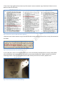
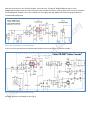
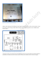
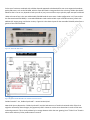
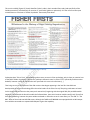
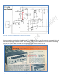
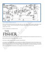
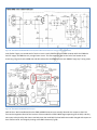
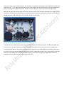
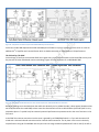
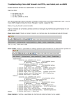
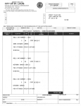
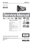
In Search of the Golden Cascode (Debunking The Myth of the Golden Synchrode?)
By member callsign:WopOnTour for the Rocky Mountain Radio and Audio Society
I believe that I may need to clarify exactly what I have been claiming at our most recent meetings (and numerous
subsequent emails) with respect to inconsistencies that we’ve all observed being said, posted, and published- regarding
the Fisher brand FM tuners and receivers equipped with so-called “cascode” or “Golden Cascode” front-ends. With so
many vintage audio “experts” out there in cyberspace contributing to the mass confusion in this regard, it’s time to setthe-record-straight, so to speak. Many of you have requested my assistance in this regard, which generated this article
for our RMRAS newsletter.
So we might as well start at the beginning- What’s a cascode?
In vacuum tube electronics, a cascode connection (sometimes incorrectly called cascade) is a gain stage where the
cathode of a valve is directly connected to the plate of another valve. This is typically done with triodes, often using
“dual” triodes housed within the same envelope. This coupling may include a resistor, capacitor or even an inter-stage
element such as a transformer or autoformer. A cascode amplifier connection can also be created using a pair of solidstate components such as BJTs or FETs (aka a Darlington Pair). Figure 1 is a typical vacuum tube cascode connection
schematic, as created by Tube-Cad™.
Figure 1- Twin Triode Cascode Amplifier (Courtesy of Tube-Cad™)
While a simplification, in a sense the upper triode’s cathode acts as a constant current source (CSS) for the lower triode’s
plate. There are a few different variations, but the bottom line is there will be some form of direct coupling of a cathode
to a plate.
*Additional information on cascoded pair variants (such as SRPP, Cascoded Cathode Follower etc) can be found at:
http://www.glass-ware.com/tubecad/TC_Tube_Circuit_Descriptions.html
What’s a cascode “front-end”?
A cascode amplifier is commonly used at radio and video frequency signal entry points aka “the front-end”, due to its
high gain and low noise, most specifically within the FM frequency bandwidth. Immediately following the antenna entry
point, the front-end of an FM tuner typically includes an RF amplifier, local oscillator, and a mixer. This would be
followed by a series of intermediate frequency (IF) amplifiers, passing through the clipping windows of a sequence of
amplitude limiter circuits, after which the audio program is separated from its carrier within the detector, prior to final
amplification by the various audio frequency gain stages.
Figure 2- FM Tuner Sections
But as most have discovered in many aspects of home audio sound, you’re final sonic qualities will generally only be as
good as your front-end, and the cascode front-end has carried a reputation for superior FM performance.
Figure 2 is the cascode connection at the RF amplifier front-end of an H.H. Scott model 310 FM tuner (note the 300 ohm
antenna connection to the grid of the 6BS8 triode). While it is coupled by a .001uf capacitor, the plate of the one half of
the 6BS8, is clearly connected to the cathode of its other half (the 6BS8 is a dual triode). The amplified signal would then
continue on to a 6U8A triode/pentode, which acts as the oscillator/mixer.
Figure 3- H.H. Scott FM Tuner (circa 1959)
The 1st-generation H.H. Scott tube tuner designs incorporated the 6BS8 RF amplifier and 6U8A oscillator tubes housed
within a modular "Silver-plated" tuner assembly. All early H.H. Scott FM tube tuners, with few exceptions, used this
"Scott-standard" 2-tube, Cascode FM front-end, which was sometimes referred to as the "Z-FM-3" assembly. Early H.H.
Scott receivers such as the model 340 also used an identical cascode arrangement. As an aside note H.H. Scott
eventually went to compactron tubes in their front-end’s RF amp (6M11) and eventually (like many manufacturers)
condensed form-factor nuvistors. The point here being cascode and nuvistor front-ends were commonly used by
manufacturers other than Fisher. The circuit schematic (not the tube # itself) will be required to determine this.
To get to the bottom of GOLDEN cascode however, I find we must start with Fisher’s stand-alone tuners. Early Fisher FM
tuners (monophonic) also used a cascode front-end dating all the way back to the early 50s, as shown in this list of
“Fisher Firsts” (Fig 4) gleaned from almost any Fisher owner’s manual. (Another copy of which we’ll discuss in more
detail a bit later in this article)
Figure 4- Fisher Firsts (From a 1964 Fisher Owner’s Manual)
And while I wasn’t able to locate a copy of the 1955 FM-40 schematic, below is the text from an early-50s brochure for
the FM-40
Figure 5- Fisher Model FM-40 Tuner Specifications
In just a few years, Fisher’s more advanced FM tuners such as the FM-60 (or KM-60 Strata-Kit version) and the MPX
stereo FM-100 were also equipped with a cascode front end, and was dubbed the “Golden Cascode” by the Fisher
marketing machine. They even silk-screened the moniker directly onto the tuner chassis, adjacent to V1.
Figure 6- Fisher Model KM-60 Tuner Chassis Markings
Note that in these tuners the “Golden Cascode” front end is the “frame grid” 6DJ8/ECC88 tube and V2 is the
6AQ8/ECC85 oscillator/mixer (not technically part of the cascode connection). Unfortunately I did’t have a full schematic
for the FM/KM-60; however, here is the schematic for the slightly later FM-100B model clearly showing the identical
cascode 6DJ8 configuration.
Figure 7- Fisher FM-100B Tuner Front-End Schematic
In fact, even the venerable stereo FM-200 model used the exact same 6DJ8 as its “Golden Cascode” …
Figure 8- Fisher Model FM-200 with Golden Cascode
and even its chassis was labeled as such (Fig 9).
Figure 9- Fisher Model FM-200B Chassis Markings
However, when looking at the FM-200B tube layout (Figure 10 taken from a genuine Fisher service manual), it clearly
shows that the signal entering the 6DJ8 “Golden Cascode” tube was eventually piped into a pair of 6CW4 Nuvistor
miniature tubes.
Figure 10- Fisher FM-200B Chassis Layout (from Fisher Service Manual)
Looking more closely at the schematic for the FM-200B (Figure 12) one can see that while the cascode RF amplifier is
maintained, the oscillator and mixer has been revised to include a pair of 6CW4 nuvistors. Nuvistors are highly
integrated tube electronics housed within a small, thimble-sized metallic envelope. In a sense, nuvistors represented the
“bridge” between vacuum tubes and solid-state, transistorized circuits. One of their first applications (besides military)
was in FM tuners due to their VHF capability, temperature stability, low noise, and smooth linearity.
Figure 11- RCA 6CW4 Nuvistor Tube (*Courtesy National Valve Museum)
So was THIS the infamous “Golden Synchrode” then? Hard to say being that, unlike cascode, there appears to be no
known definition for a “synchrode” connection in any electronics texts that I could find. (Try plugging the word
“synchrode” into a search engine and see what you get!) But what we do know is this basic point of entry configuration
is what forms the initial building block of the synchrode front-end. More on that in a bit.
However to this point in time (circa 1960-61) the cascoded 6DJ8 front door is clearly still being referred by Fisher as
“Golden Cascode”.
Figure 12- Fisher FM-200B with Golden Cascode and Nuvistor Front-End
So the use of nuvistors combined with a Golden Cascode appeared to be destined for even more expensive broadcast
quality FM tuners, such as the FM-1000, which is often described in vintage audio circles as having “Golden Synchrode”.
Whether that is true or not, depends on who you talk to, but just one of the many myths this paper attempts to debunk.
What we know as fact is the rare and desirable FM-1000 used the exact same 3 tube configuration in it’s front-end as
the aforementioned FM-200B (i.e. a cascoded 6DJ8 twin triode combined with a pair of 6CW4 nuvistors), albeit with
additional IF stages, gangs, and limiter circuitry. Figure 14 is the chassis layout for the venerable FM-1000, taken from a
genuine Fisher Service Manual.
Figure 13- Fisher FM-1000 Tuner
Figure 14- Fisher Model FM-1000 Tuner Golden Cascode Front End
Golden Cascode? - Yes , Golden Synchrode? – ummm No Not Quite!
Now while I do not dispute the “Golden Synchrode” moniker had some sort of technical rationale within Fisher that
might be reflected by these changes, they apparently didn’t choose to use the term themselves in much of their own
marketing materials. This is clearly evident by its strange absence within the ever-growing list of “Fisher Firsts” found in
almost each and every Fisher product owner’s manual.
This one circa 1966, (Figure 15) clearly identifies Fisher’s pride in their cascoded front-ends (and specifically of the
Golden persuasion), but absolutely no mention of “synchrode” (golden or otherwise). So if the use of nuvistors post
cascode does not constitute a “Golden Synchrode” then exactly what does?
Figure 15- More "Fisher Firsts" (Taken from a 1966 Fisher Owner's Manual)
So despite these “Fisher Firsts” acknowledging almost every nuance in Fisher technology, why is there no mention here
of the 1963 “Golden Synchrode”? Who knows, perhaps it because it wasn’t a Fisher First? I personally find that notion
doubtful; however could it be because the term synchrode isn’t even in the dictionary! ;)
That brings us now to the infamous Fisher FM receivers that began appearing in the late 50s. How did these
developments in front-end technology affect the value leaders of the Fisher line-up? Enquiring minds want to know!
So let’s begin with the TA series that pretty much started it all, beginning with the original 500, 600, and 800 models.
Not to be confused with the B and C models that followed them, these initial receiver models usually had a TA prefix in
their chassis labeling, however they were seldom marketed or referred to as such- more often just “The 500” or “The
800”. None of them had true MPX FM stereo, although the TA600 and TA800 did come equipped with an MPX output
that could be connected to a separate MPX adapter to gain that capability.
The original model 500 (Figure 16) was not a stereo receiver, it was monophonic.
Figure 16- Fisher Model 500 AM/FM Receiver
But it had both AM and FM capability, AND as one can see from its front-end schematic (Figure 17), a cascode FM frontend (capacitor coupled).
Figure 17- 1957 Fisher Model 500 FM Receiver Front-End
Now comparing that to the front-end schematic (Fig. 18) for the 1960 model TA600, a single 6AQ8 tube is now used both
for the RF amp and the oscillator/mixer front-end. The cascode connection within this triode is especially obvious, due
to the way the schematic more correctly aligns the cathode above the plate. (much text book discussion of cascode
tubes, often refers to the “upper” and “lower” triode within the circuit)
Figure 18- 1960 Fisher Model TA600 FM Cascode Front-End Schematic
So what about the top-of-the-line Fisher 800 model? The TA800 was often the only Fisher receiver advertized back in the
early 60s as employing a “Golden Cascode” tuner. Here’s a copy of a Fisher 800 ad from the 1961 Radio Shack catalog
(Fig. 19). An adjacent ad for the model 101-R tuner is also shown- Golden Cascodes for all!
Figure 19- Fisher TA800 Advertising Ad (Radio Shack Catalog 1961)
And following up with Figure 20, the schematic for the original 1960 Fisher model 800 (the TA800) Yes, we find the
“classic” Golden Cascode ECC88/6DJ8 into an ECC85/6AQ8 mixer-oscillator (Remember the FM-100B tuner?). As an
interesting aside note, the TA800 was also equipped with a small, blunt cut wire antenna connected to the grid circuit of
the mixer that apparently was to act as some sort of noise cancellation device that improved reception (the item labeled
“gimmick” in this schematic from SAMs folder 530-5). I can find no reference as to the true performance significance,
but interesting trivia nonetheless.
Figure 20- 1960 Fisher TA800 FM Cascode ECC88 Front End
In late 1960 Fisher updated the 500 to the 500S (S for Stereo) and it joined the existing stable of “TA” 600 & 800
receivers. Like the TA models it was AM/FM, shared the polished brass plated faceplate and like the 600 was equipped
with a quad of 7189 output tubes (the earlier 500 mono used KT66 or EL34 depending on model year) however was now
rated at 5 watts higher (45wpc vs. 40wpc) than the TA600.
Figure 21- 1960 Fisher Model 500S AM/FM Receiver - 45 wpc
The 500S is in many ways quite similar to the 600, however it had “solid state” voltage rectification (the 600 used a pair
EZ80 rectifiers) and revised chassis layout with slightly smaller transformers. However another difference was its FM
tuner front-end, looking at a schematic of the FM tuner used in the 500S (Fig 22).
Figure 22- 1960 Fisher 500S FM Tuner Front End
So can you find the cascode connection? No? Well neither can I! That’s because the front door’s 6AQ8 triodes are not
connected “in cascode”- but a more conventional, less complex (and perhaps less expensive?) single-tube RF
amplifier/mixer combo.
In short, the 500S is NOT a cascode front-end.
So what about the other great Fisher stereo receiver models that appeared over the period of the next 5-6 years or so,
often considered to be the Golden Age of audio in America.
Were they ALL Golden Cascode? Golden Synchrode? Something else?
Let’s begin with the venerable 500B. None would dispute the 500B was THE FM stereo receiver that launched a very
dominant period for Fisher in the home audio marketplace. The 60-watt 500B didn’t have an AM tuner. Fisher faithful
would say that was to make room for the multiple IF stages and full MPX stereo and massive transformers. As such it’s
widely assumed, published and stated that it was equipped with the Golden Cascode front-end.
Below (Figure 23) is the schematic from the genuine 1962 Fisher Service Manual for the 1962 model 500B (serial
numbers 20001-39999).
Figure 23- 1962 Fisher Model 500B Dual Triode (Non-Cascode) FM Tuner Front-End
Surprise! Surprise! The vaunted 500B so usually associated with unrivaled FM performance that’s often attributed to it
having the Golden Cascode front-end actually used a single dual triode. In this case the 6AQ8 is connected in typical RF
amplifier fashion with the second stage of the amplifier/mixer using a more conventional grounded cathode (plate
follower) arrangement. Unlike the previous models, I could find no Fisher marketing materials stating the 500B used
“Golden Cascode” and likely for very good reason. It didn’t have one.
Now just for my amusement let’s compare that to the 1961 Harman Kardon TA260 front end (as most of you know I’m a
huge H/K fan).
Figure 24- 1961 Harman Kardon Model TA-260 "Festival II" Receiver FM Tuner Front-End
So, the H/K receiver isn’t using a cascode RF amplifier either. But as one can see it is very similar to the Fisher 500B. A
single tube, grounded grid RF amplifier feeds into the conventional plate follower at the mixer/oscillator (much like the
500B), however with an additional triode sandwiched in between consisting of its Automatic Frequency Control (AFC)
circuitry. My point here is that the H/K receiver’s front-end really isn’t that different from the 500B. This despite all-toooften being referred to as inferior in design to the 500B’s cascode front-end which might make sense- if it had one.
I’ve also heard the 500B’s superior FM performance was attributed to it having up to 4 IF amplifiers and 3 limiters
(almost as many as the much more expensive FM-1000 tuner). So let’s debunk that while we’re at it shall we? Below is
the chassis layout and stage labeling as found in the same 1962 Fisher 500B Service Manual.
Figure 25- 1962 Fisher 500B Chassis Layout
Count ‘em, two IF stages and 2 limiter stages. So nothing here at least seems to substantiate the 500B’s legendary FM
performance. I don’t dispute that it has excellent FM, but it’s not for the reasons so widely attributed. Now there were
significant changes in the up-coming 500C tuner however I am attempting to complete this summary as chronologically
as possible, so let’s save the best for last and take a look first at what happened to the Fisher 800 model.
The 800B and the 800C were also major contributors to Fisher’s reputation for superb stereo reproduction and AM/FM
tuner performance throughout the 1960s. As we’ve seen earlier the first generation model TA800 used a “Golden
Cascode” FM front end. So can we assume this continued? Let’s take a close look under the hood of the 1962 Fisher
800B. Figure 26 is the front end schematic for the Fisher model 800B (serial numbers 10001-19999)
Figure 26- 1962 Fisher Model 800B FM Front-End (Fisher 500C Service Manual for serial numbers 10000-19999)
Look familiar? Again, no cascode and in fact the circuit is nearly IDENTICAL to the 500B. However while the 500B also
had 2 IF stages, this 800B has only a single limiter circuit. This was most likely due to the lack of real-estate on the
chassis (Fig 27) given that the 800B also had AM radio (unlike the 500B).Note the twin EM84A “magic eye” tuning tubes.
Figure 27- 1962 Fisher Model 800B Chassis Layout
Well OK then. We’ve established that the 500B and 800B receivers were virtually identical with respect to their FM
front-end arrangement. But the final versions of these models the 500C & 800C began appearing late in 1963, and they
were soon to be joined by their lower-cost baby sister the model 400. So how had these models changed with respect to
their FM front-ends. Let’s begin by looking at the 800C schematic (Fig 28).
Figure 28- 1963 Fisher Model 800C Receiver with 6GK5-6AQ8 (Non-Cascode) FM Tuner Front-End
Well there certainly was a change. The all-new tube in the 800C front end is using the sub-miniature (T5½) 6GK5, a
single triode design intended as a low-noise VHF RF amplifier. This tube has a frame grid construction in a glass envelope
but IS NOT a nuvistor as it is so often portrayed. Its output is fed into the single 6AQ8 as oscillator/IF amp. What’s very
strange with the 800C is while no mention of this feature in the owner’s manual, there is often (on some C models) a
small label on top of the tuner identifying the 6GK5-6AQ8 as “Golden Synchrode” yet there does not appear to be any
sort electronic of rationale to justify that. Since the 6AQ8 is nothing special, does this mean “Syncrode” is just the
inclusion of this new single triode front-end? Was this “Golden Syncrode”?
Figure 29- 1963 Fisher Model 800C AM/FM Receiver
Not cascode, but quite possibly synchrode (whatever that is) the last 800 model instead focused more on the “whistles
and bells” such the automatic stereo beacon, needle type signal tuning (earlier models used magic eye tubes) and
improved tape and phono input features. But the fact remains is the only Fisher 800 model that used cascode was the
original early-60s TA800 model.
So just what WAS synchrode? As previously mentioned there appears to be no amplification term or definition within
the realm of electronics that seems to allude to it. But as far as I’ve been able to ascertain, the actual term “Golden
Synchrode” made its first appearance with the launch of the 65-watt MPX equipped Fisher Model 400 sometime late in
1963. Model 400 production continued through to the end of Fishers tube era, with numerous running changes (without
a model designation suffix change) taking place over the following year or two. Below is an excerpt from a 1964 owner’s
manual for the Fisher model 400 (Fig 30).
Figure 30- 1964 Fisher Model 400 Owner's Manual Introduction
Now let’s look at the 1964 Model 400 schematic shall we?
Figure 31- 1964 Model 400 Receiver FM Front End Schematic (late build serial number 48001 and up)
The first thing you notices is the 1st tube has been changed to a 6HA5 sub-miniature (T-5 ½) single triode tube with
electrical characteristics and stature VERY similar to the 6GK5 used in the 800C. The next tube is an EC92/6AB4 single
triode (also sub-mini) as the oscillator/mixer and eventually coil-coupled to the grid (g1) of an EF93/6BA6 pentode which
represents the 1st of 3 IF stages. But apparently the use of this single triode as the V1 point of entry IS (according to the
owner’s manual) Fisher’s Golden Synchrode- how anti-climactic! Nuvistors, apparently had nothing to do with it!
About all I can glean that’s special about this circuit is its unique use of a pair of single triode tubes (inter-stage coupled),
and I guess a somewhat loose assimilation of a cascode-like connected circuit represented by the plate of the EC92 and
the cathode of the EC93 coupled via the Z1 coils.(the ‘chrode of synchrode?).
Figure 18- Fisher Model 400 Chassis Photo (With Golden Synchrode)
Could this be Fisher’s ONLY receiver with Golden Synchrode? Well the similarities between the 400 and the 800C lead
me to ascertain it too was “Golden Synchrode” even though there doesn’t seem much from Fisher to support that.
It should also be noted that while this was the latest wiring schematic for the model 400 that I was able to obtain from
my archives, (for serial numbers 48001 and up) looking at earlier model 400 schematics that I have however, there were
only minor circuit differences in the front-ends, while there were much more significant changes (both tubes and
arrangement) further downstream in the tuner (see Figure 32)
Figure 32- Comparison of Chassis Layout Fisher Model 400 Early-Late Production
So the later model 400 displaced the 6H56 and added pare of 6AU6 in its place, stretching out the tuner to create an
additional 4th IF amplifier and a second limiter which no doubt came with an improvement in FM performance.
The Fisher King- The 500C
So that brings us finally to the venerable 500C that a great many claim has the ultimate in tube based FM circuitry and
the pinnacle of Fisher tube-based receiver technology. Figure 33 is the schematic for a 1964 Model 500C.
Figure 33- 1964 Fisher Model 500C Receiver with "Golden Synchrode" 6HA5+6CW4 Nuvistor Front End
Based on this diagram it should be clear that while this obviously isn’t a Golden Cascode, it does appear (based on what
we’ve learned about the model 400) to have some the characteristics of the so-called Golden Synchrode (and I’m very
tempted to place a ™ symbol here) but now with potential performance improvements thru the use of nuvistors in the
front-end.
In the 500C the antenna connection into the tuner is greeted by an EC900/6HA5 which is a 7-pin sub-miniature VHF
triode with a twinned cathode connection and an internal shield connection. The V1 plate in this case is inductively
coupled both to the grid of V18 6CW4 nuvistor (thru the inter-stage relationship between RF coils L2 and L3) as well as
the grid of V2 nuvistor through L4. Z1 then couples the connection to V3 the 1st IF amplifier a 6HR6, yet another T5 ½
sub-miniature tube, (they were in vogue after all) but this one a sharp-cutoff pentode.
Figure 34- 1964 Fisher 500C Chassis Layout (serial numbers 30001-59999 inclusive)
So the final iteration of the famous Fisher 500 receivers’ chimes in with no less than 4 IF gain stages and 2 limiters. Plus
in an interesting twist, the 500C front-end appears to be a “blend” of the 400’s “Golden Synchrode” and the much more
expensive FM-1000 tuner layout! So I would submit to everyone that THIS arrangement just might be the Holy Grail of
Fisher tuners! <insert trumpets here> “All HAIL The 24-Karat Golden Synchrode!”
So where I am going with all this?
I have absolutely no doubt, that the Fisher FM tuners and receivers produced during the Golden Age of HI-FI and had
performance that represents some of the best that has ever existed. My intentions for this article were simple, and that
was to better define what constitutes cascode and synchrode front-end circuitry and to establish exactly which Fisher
models used them. Many of our members are spending large amounts of money purchasing these vintage receivers, and
their enjoyment is certainly enhanced by getting exactly what was expected. My goal was to educate to the level
necessary to make informed bidding and/or purchasing decisions when buying these items on-line and during local
equipment swap meets and ham-mer fests.
And now my disclaimer.
Now as everyone that’s ever “tinkered” with vintage audio circuitry (or even more seriously as a service technician) will
tell you that manufacturers OFTEN made running changes to their circuitry, design and/or component compliment.
Additionally there were often numerous data errors and false information spread by the marketing channels in the form
of magazine and catalog advertising. Combine that with unintentional human error made during schematic creation in
aftermarket service products such as NRI schematics and SAMs folders, makes for all sorts of variables that are just out
of my or anyone else’s control. Thus it makes nailing down empirically exact and 100% reliable data, specifications,
information and schematics a near an impossible task even today, let alone for an era that was nearly 50 years ago.
However I can tell you that I have compiled this information with only the best intentions, using the most reliable
information available and to my disposal, but I make no absolute guarantees as to its accuracy.
That being said, if anyone has data that might add to or supplement what I have done here or that even absolutely
conflicts with the content as stated in this article, please feel free to contact the writer at [email protected]
Enjoy Your Vintage Audio!!