1
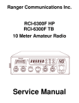
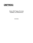
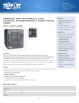
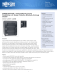
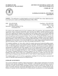
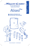
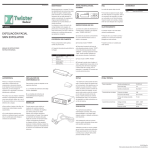
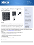
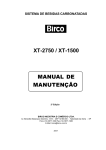
SS-3900EGHP TABLE OF CONTENTS PAGE CHAPTER 1 SPECIFICATIONS 1.0 General . . . . . . . . . . . . . . . . . . . . . . . . . . . . . . . . . . . . . . . . . . . . . . . . . . . . . . . . . . . . . . . 1.1 Transmitter . . . . . . . . . . . . . . . . . . . . . . . . . . . . . . . . . . . . . . . . . . . . . . . . . . . . . . . . . . . . 1.2 Receiver . . . . . . . . . . . . . . . . . . . . . . . . . . . . . . . . . . . . . . . . . . . . . . . . . . . . . . . . . . . . . . 2 2 2 CHAPTER 2 OPERATION 2.0 Introduction . . . . . . . . . . . . . . . . . . . . . . . . . . . . . . . . . . . . . . . . . . . . . . . . . . . . . . . . . . . 2.1 Control & Connections . . . . . . . . . . . . . . . . . . . . . . . . . . . . . . . . . . . . . . . . . . . . . . . . . . 2.1.1 Front Panel . . . . . . . . . . . . . . . . . . . . . . . . . . . . . . . . . . . . . . . . . . . . . . . . . . . . . . . . . . . . 2.1.2 Rear Panel . . . . . . . . . . . . . . . . . . . . . . . . . . . . . . . . . . . . . . . . . . . . . . . . . . . . . . . . . . . . 2.2 Microphone . . . . . . . . . . . . . . . . . . . . . . . . . . . . . . . . . . . . . . . . . . . . . . . . . . . . . . . . . . . 2.3 Operation . . . . . . . . . . . . . . . . . . . . . . . . . . . . . . . . . . . . . . . . . . . . . . . . . . . . . . . . . . . . 2.3.1 Procedure To Receive . . . . . . . . . . . . . . . . . . . . . . . . . . . . . . . . . . . . . . . . . . . . . . . . . . . 2.3.2 Procedure To Transmit . . . . . . . . . . . . . . . . . . . . . . . . . . . . . . . . . . . . . . . . . . . . . . . . . . 2.4 Alternate Microphones And Installation . . . . . . . . . . . . . . . . . . . . . . . . . . . . . . . . . . . . . 3 3 3 5 6 6 6 6 7 CHAPTER 3 CIRCUIT DESCRIPTION 3.0 Introduction . . . . . . . . . . . . . . . . . . . . . . . . . . . . . . . . . . . . . . . . . . . . . . . . . . . . . . . . . . . 3.1 PLL Circuit . . . . . . . . . . . . . . . . . . . . . . . . . . . . . . . . . . . . . . . . . . . . . . . . . . . . . . . . . . . 3.2 Receiver Circuit . . . . . . . . . . . . . . . . . . . . . . . . . . . . . . . . . . . . . . . . . . . . . . . . . . . . . . . 3.3 Transmitter Modulation Circuit . . . . . . . . . . . . . . . . . . . . . . . . . . . . . . . . . . . . . . . . . . . 3.4 Transmitter Amplifier Circuit . . . . . . . . . . . . . . . . . . . . . . . . . . . . . . . . . . . . . . . . . . . . . 8 8 8 8 8 CHAPTER 4 ALIGNMENT 4.0 Required Test Equipment . . . . . . . . . . . . . . . . . . . . . . . . . . . . . . . . . . . . . . . . . . . . . . . . 4.1 Alignment Procedures . . . . . . . . . . . . . . . . . . . . . . . . . . . . . . . . . . . . . . . . . . . . . . . . . . . 4.1.1 PLL Alignment . . . . . . . . . . . . . . . . . . . . . . . . . . . . . . . . . . . . . . . . . . . . . . . . . . . . . . . . 4.1.2 Transmitter Alignment . . . . . . . . . . . . . . . . . . . . . . . . . . . . . . . . . . . . . . . . . . . . . . . . . . 4.1.3 Receiver Alignment . . . . . . . . . . . . . . . . . . . . . . . . . . . . . . . . . . . . . . . . . . . . . . . . . . . . 11 11 11 12 13 CHAPTER 5 MAINTENANCE 5.0 Precautions . . . . . . . . . . . . . . . . . . . . . . . . . . . . . . . . . . . . . . . . . . . . . . . . . . . . . . . . . . . . 5.1 Periodic Inspection . . . . . . . . . . . . . . . . . . . . . . . . . . . . . . . . . . . . . . . . . . . . . . . . . . . . . . 5.2 Fuse Replacement . . . . . . . . . . . . . . . . . . . . . . . . . . . . . . . . . . . . . . . . . . . . . . . . . . . . . . 16 16 16 CHAPTER 6 DIAGRAMS AND PART LIST 6.0 PCB Layout & Part List . . . . . . . . . . . . . . . . . . . . . . . . . . . . . . . . . . . . . . . . . . . . . . . . . 17 CHAPTER 1 SPECIFICATIONS SS-3900EGHP 1.0 GENERAL Model Frequency Range Emission Modes Frequency Control Frequency Tolerance Frequency Stability Operating Temperature Range Microphone Meter Function Input Voltage Transmit Current Drain: Receive Current Drain: SS-3900EGHP 10 Meter: 28.015 ~ 28.465MHz AM(A3)/FM(F3)/LSB,USB(A3J)/CW(A1) Phase Lock Loop (PLL) synthesizer ± 0.005 % ± 0.001 % -30°C to +50°C Plug-in (4 pin), Dynamic PTT, 500 Ω Meter shows relative signal strength, RF output power and SWR level. AM Full Mod. Squelched Max. Audio Output Antenna Connector Dimensions Weight 13.8V DC nominal ±15% < 5A < 0.6A < 1.2A UHF, SO239 7-7/8”(W) x 10-3/4”(D) x 2-3/8”(H) 5 lb. 1.1 TRANSMITTER RF Power Output RF Transmit Modes Modulation Harmonics And Spurious Emissions Carrier Suppression Audio Frequency Response Antenna Impedance AM/FM/CW: 9W RMS ; SSB: 25W PEP AM/FM/SSB/CW A3E/16F3/J3E/A1A > -50 dB > -35 dB 300 to 2500 Hz 50 Ohms 1.2 RECEIVER Sensitivity Intermediate Frequency Image Rejection Adjacent Channel Selectivity RF Gain Control Automatic Gain Control (AGC) Figure Of Merit Squelch Noise Blanker Audio Output Power Audio Frequency Response Built-in Speaker External Speaker (Not Supplied) AM: < 1.0 µV For 10dB S+N/N FM: < 0.5 µV For 12dB S+N/N SSB/CW: < 0.5 µV For 10dB S+N/N 10.695 MHz (AM-1st, SSB), 455 KHz (AM-2nd) > 50 dB > 60 dB 45 dB adjustable for optimum signal reception >70 dB for 50 mV for 10 dB Change in Audio Output Adjustable; threshold less than 0.5 µV RF type 2.5W @ 10% THD 300 to 2500 Hz 8 Ohms, 4 Watts 8 Ohms, 4 Watts (SPECIFICATIONS SUBJECT TO CHANGE WITHOUT NOTICE) -1- CHAPTER 2 OPERATION SS-3900EGHP Figure 2-1 Front Panel 2.0 INTRODUCTION This section explains the basic operating procedures for the SS-3900EGHP Amateur 10 meter mobile transceiver. 2.1 CONTROL AND CONNECTIONS 2.1.1 FRONT PANEL Refer to the above Figure 2-1 for the location of the following controls. 1. ON/OFF VOLUME CONTROL This knob controls the volume and power to the radio. To turn radio on, rotate the knob clockwise. Turning the knob further will increase the volume of the receiver. 2. SQUELCH CONTROL This knob is used to eliminate background noise being heard through the receiver, which can be disturbing when no transmissions are being heard through the receiver. To use this feature, turn the knob fully counterclockwise and then turn clockwise slowly until the background noise is just eliminated. Further clockwise rotation will increase the threshold level which a signal must overcome in order to be heard. Only strong signals will be heard at a maximum clockwise setting. 3. MIC GAIN CONTROL Adjusts the microphone gain in the transmit modes. This controls the gain to the extent that full talk power is available several inches away from the microphone. -2- 4. RF GAIN CONTROL This control is used to reduce the gain of the RF amplifier under strong signal conditions. 5. ECHO/TIME CONTROL This control is used to control the echo effects. 6. BAND SELECTOR This switch is used to select the band. 7. MODE SWITCH This switch allows you to select one of following operating modes: CW/FM/AM/LSB/USB. 8. COARSE/FINE CONTROL Allows tuning of the receive or transmit frequency above or below the channel frequency. Although this control is intended primarily to tune in SSB/CW signals, it may be used to optimize AM/FM signals as described in the Operating Procedure paragraphs. Coarse operates both TX/RX but Fine only in RX. 9. CHANNEL SELECTOR This control is used to select the desired transmit and receive channel. 10. FRONT PANEL METER The front panel meter allows the user to monitor signal strength, RF output power and SWR level. 11. RF POWER H/M/L SWITCH This switch allows the user to select HI, MID or LO RF power output. 12. NB-ANL/OFF SWITCH When the switch is place in the NB/ANL position, the Automatic Noise Limiter (ANL) in the audio circuits and the RF Noise Blanker (NB) is also activated. The RF Noise Blanker is very effective in eliminating repetitive impulse noise such as ignition interference. 13. S-RF/SWR SWITCH In the S-RF position, the meter swings proportionally to the strength of the received signal. When transmitting, the meter indicates relative RF output power. When in the SWR position, the Standing Wave Ratio (SWR) of your antenna. There are no adjustment because the SWR circuit in this radio calibrates itself automatically. 14. TALKBACK (TB) SWITCH This switch is used to monitor the sound feedback effects. 15. RX/TX LED The red LED indicates the unit is in the transmit mode. The green LED indicates the unit is in the receive mode. 16. CHANNEL DISPLAY The channel display indicates the current selected channel. 2.1.2 REAR PANEL -3- Figure 2-2 represents the location of the following connections: Figure 2-2 Rear Panel 1. ANTENNA This jack accepts a 50 ohms coaxial cable with a PL-259 style plug. 2. POWER This accepts 13.8 VDC power cable with built-in fuse. The power cord provided with the radio has a black and red wire. The black goes to negative and the red goes to positive. 3. F.C. This connector is used for an external frequency counter which indicates the frequency of the selected channel. 4. CW KEY The CW key is used for Morse Code operation. To operate this mode, connect a CW key to this jack, and place the MODE switch in the CW position. 5. EXTERNAL SPEAKER This jack accepts a 4 - 8 ohm, 5watt external speaker. When the external speaker is connected to this jack, the built-in speaker will be disabled. 2.2 MICROPHONE -4- The receiver and transmitter are controlled by the push-to-talk switch on the microphone. Press the switch and the transmitter is activated, release switch to receive. When transmitting, hold the microphone two inches from your mouth and speak clearly in a normal voice. This transceiver comes complete with a low impedance dynamic microphone. 2.3 OPERATION 2.3.1 PROCEDURE TO RECEIVE 1. Be sure that power source, microphone and antenna are connected to the proper connectors before going to the next step. 2. Turn unit on by turning the VOL knob clockwise. 3. Set the VOL to a comfortable listening level. 4. Set the MODE switch to the desired mode. 5. Listen to the background noise from the speaker. Turn the SQ knob slowly clockwise until the noise just disappears. The SQ is now properly adjusted. The receiver will remain quiet until a signal is actually received. Do not advance the control too far or some of weaker signals will not be heard. 6. Set the CHANNEL selector switch to the desired channel. 7. Set the RF GAIN control fully clockwise for maximum RF gain. 8. Adjust the COARSE/FINE control to clarify the SSB signals or to optimize AM/FM signals. 2.3.2 PROCEDURE TO TRANSMIT 1. Select the desired channel of transmission 2. Set the MIC GAIN control fully clockwise. 3. If the channel is clear, depress the push-to-talk switch on the microphone and speak in a normal voice. 2.4 ALTERNATE MICROPHONES AND INSTALLATION -5- For best results, the user should select a low-impedance dynamic type microphone or a transistorized microphone. Transistorized type microphones have low output impedance characteristics. The microphones must be provided with a four-lead cable. The audio conductor and its shielded lead comprise two of the leads. The third lead is for transmit control and fourth is for receiving control. The microphone should provide the functions shown in the schematic below (Figure 2-3). 4 WIRE MIC CABLE Pin Number Mic Cable Lead 1 Audio Shield 2 Audio Lead 3 Transmit Control 4 Receive Control Figure 2-3 Your Transceiver Microphone Schematic Figure 2-4 Microphone plug pins numbers viewed from rear of pin receptacle. CHAPTER 3 -6- CIRCUIT DESCRIPTION SS-3900EGHP 3.0 INTRODUCTION This section explains the technical theory of operation for the SS-3900EGHP Amateur 10 meter mobile transceiver. 3.1 PLL CIRCUIT The Phase Lock Loop (PLL) circuit is responsible for developing the receiver’s first local oscillator signal and the transmitter’s exciter signal. The PLL circuit consists primarily of IC5, IC10, TR24, TR25 and TR26. The PLL circuit is programmed by the rotary channel switch GPS-0501. The GPS0501 communicates the correct binary data information to the programmable divider inside of IC5. IC5 then controls the VCO (Voltage Controlled Oscillator) to oscillate on the correct frequency. This signal is fed either into the receiver’s first mixer (for receive operation) or the transmitter’s mixer (for transmit operation). 3.2 RECEIVER CIRCUIT The incoming RF signal comes into the radio via the antenna and into the front-end pre-amp, TR17. The RF signal is fed into the mosfet mixer circuit of TR18 and then into the AM/FM/SSB IF section of the receiver (depending on the mode of operation). The signal is then detected by either the AM/FM detector or product detector and then fed to the audio amplifier section of the receiver and finally out to the speaker. 3.3 TRANSMITTER MODULATION CIRCUIT (i) The transmitter modulation circuit modulates the low-level RF signal from the PLL exciter circuit with the user’s audio voice signal from the microphone. The audio from the microphone is then amplified and fed into the transmit amplifier circuit. (ii) If the transceiver is in the AM mode, the AF Power amplifier modulates the last RF amplifier, which produces a true amplitude modulated RF signal. (iii) If the transceiver is in the FM mode, the audio signal is not mixed with 10.6975MHz oscillator but instead phase modulates the basic exciter signal from the PLL circuit in the TX mixer. (iv) If the transceiver is in the SSB mode, the audio signal is mixed with the 10.6975MHz oscillator for LSB and 10.6925MHz for USB in IC3. 3.4 TRANSMITTER AMPLIFIER CIRCUIT The transmitter takes the basic exciter signal from the TX mixer and amplifies it through a series of amplifiers consisting of TR46, TR45, TR44, TR43 and TR56 where it is then sent out to the antenna connector. -7- -8- CHAPTER 4 ALIGNMENT -9- 4.0 REQUIRED TEST EQUIPMENT DC Power Supply (13.8VDC, 10A) RF Wattmeter (25~60 MHz, 50W) Multimeter (Digital) Automatic Modulation Meter Audio Signal Generator Frequency Counter (100 MHz) RF Signal Generator (100 MHz) Automatic Distortion Meter Oscilloscope (50 MHz) Sinad Meter 4.1 ALIGNMENT PROCEDURES This transceiver has been aligned at the factory and does not require any adjustments at installation. The required test equipment listed are used for the test setup or alignment shown in Figure 4-1 Transmitter Test Setup and Figure 4-2 Receiver Test Setup. These test setups are used in part or total during the following adjustments and refer to Page 15 for adjustment location. 4.1.1 PLL ALIGNMENT ITEM VCO AM Frequency U.U.T. SETTING ADJUST POINT Disconnect “short PCB” from TP7, TP8 & TP9. Set radio to A band, CH 1 AM RX mode. Set COARSE/FINE control at 12 o’clock. Connect Multimeter to TP2(R116). L17 Set radio to 25.615 MHz & 28.305MHz. Connect Oscilloscope to TP3(R74). L18 MEASUREMENT 1.6 VDC ± 0.1 Maximum Output and Balance Set radio to A band, CH 1 AM RX mode. Connect Frequency Counter to TP3(R74). L19 14.9200 MHz + 20Hz USB Frequency Set radio to A band, CH 1 USB RX mode. Connect Frequency Counter to TP3(R74). L20 14.9225 MHz + 20Hz LSB Frequency Set radio to A band, CH 1 LSB RX mode. Connect Frequency Counter to TP3(R74). L21 14.9175 MHz + 20Hz Set radio to A band, CH 1 AM TX mode. Connect Frequency Counter to TP3(R74). VR21 14.9200 MHz + 20Hz Set radio to A band, CH 1 AM TX mode. Connect Frequency Counter to TP5(D62). L26 10.6950 MHz + 10Hz L27 L28 10.6925 MHz + 10Hz 10.6975 MHz + 10Hz TX Frequency AM OSC SSB OSC Set radio to A band, CH 1 USB TX mode. Set radio to A band, CH 1 LSB TX mode. Modulation off. Short TR31 (Collector & Emitter). Connect Frequency Counter to TP6(R102). 4.1.2 TRANSMITTER ALIGNMENT ITEM BIAS Current U.U.T. SETTING Set radio to A band, CH 1 USB TX mode. - 10 - ADJUST POINT MEASUREMENT Modulation off. Connect current meter to TP9(+) and TP8(-). Connect current meter to TP9(+) and TP7(-). VR11 VR10,VR20 20 mA 160 mA L44,L42 Maximum Output Set radio to F band, CH 40 USB TX mode. L40,L43 Maximum Output Set radio to 25.615 MHz & 28.305MHz. L33 Maximum Output and Balance SSB ALC Set radio to D band, CH 1 USB TX mode. AF signal 30 mV, 1 KHz to microphone. VR12 25W SSB Carrier Balance Set radio to D band, CH 1 USB TX mode. AF signal 30 mV, 1 KHz to microphone. Connect Oscilloscope to antenna jack. VR7 Spurious Emission to minimum AM/FM TX Power Set radio to D band, CH 1 AM TX mode. Modulation off. Connect RF Power Meter to antenna jack. VR13 9W RF Power Meter Set radio to D band, CH 1 AM TX mode. Set S-RF/SWR switch to S/RF position. Modulation off. VR8 For a needle reading "in-between green and red bar" on TX PWR scale. CW TX Set radio to D band, CH 1 CW TX mode. Plug in CW Key. Disconnect the Mic Jack. Connect AC Voltmeter to EXT SP. VR16 200 mV AM Modulation Set radio to D band, CH 1 AM TX mode. FM Deviation Set radio to D band, CH 1 FM TX mode. Set Mic Gain Fully Clockwise. AF signal 30 mV, 1 KHz to microphone. VR14 VR5 90% 4KHz SWR Meter VR1 on ANT For a needle reading PCB of "2" on SWR scale. SSB TX Power Set radio to A band, CH 1 USB TX mode. Set Mic Gain Fully Clockwise. Set RF POWER H/M/L switch to H position. AF signal 30 mV, 1 KHz to microphone. Connect “short PCB” to TP7, TP8 & TP9. Connect RF Power Meter to antenna jack. Set radio to D band, CH 1 AM TX mode. Set S-RF/SWR switch to SWR position. Modulation off. Connect 100Ω load to antenna jack. 4.1.3 RECEIVER ALIGNMENT ITEM U.U.T. SETTING - 11 - ADJUST POINT MEASUREMENT L3,L4,L6, L7,L8,L10, L11,L12 Audio Output > 2V S/N > 10 dB Set radio to A band, CH 1 AM RX mode. RF SG setting 25.615 MHz. Set radio to F band, CH 40 AM RX mode. RF SG setting 28.305 MHz. L7,L8 L7,L8 Balance between 25.615 MHz and 28.305 MHz Set radio to D band, CH 1 FM RX mode. RF SG setting 26.965 MHz, 0.5uV. Mod 3KHz. L5 S/N > 20 dB USB Sensitivity Set radio to D band, CH 1 USB RX mode. RF SG setting 26.966 MHz, 0.25uV. Mod off. L13,L14 Audio Output > 2V S/N > 10 dB LSB Sensitivity Set radio to D band, CH 1 LSB RX mode. RF SG setting 26.964 MHz, 0.25uV. Mod off. L13,L14 Audio Output > 2V S/N > 10 dB AM Sensitivity Set radio to D band, CH 1 AM RX mode. Set RF Gain Fully Clockwise. Set SQ Control Fully Counter Clockwise. Set NB-ANL/OFF switch to OFF position. Set VOL Control at 2 o’clock. Connect RF SG to antenna jack. Frequency 26.965 MHz, 1uV. Mod 30%. FM Sensitivity NB Adjust Set radio to D band, CH 1 AM RX mode. L1,L2 Set NB-ANL/OFF switch to NB/ANL position. RF SG setting 26.965 MHz, 100uV. Mod off. Connect Multimeter to TP1(D2). DC voltage to max. > 2.0V AM Squelch Set radio to D band, CH 1 AM RX mode. Set SQ Control Fully Clockwise. RF SG setting 26.965 MHz, 1mV. Mod 30%. VR4 Slowly Adjust very slowly until squelch just open. SSB Squelch Set radio to D band, CH 1 USB RX mode. Set SQ Control Fully Clockwise. RF SG setting 26.966 MHz, 1mV. Mod off. VR3 Slowly Adjust very slowly until squelch just open. AM S-Meter Set radio to D band, CH 1 AM RX mode. VR1 Set S-RF/SWR switch to S/RF position. RF SG setting 26.965 MHz, 100uV. Mod 30%. For a reading of "9" on the "S" scale. SSB S-Meter Set radio to D band, CH 1 USB RX mode. RF SG setting 26.966 MHz, 100uV. Mod off. For a reading of "9" on the "S" scale. - 12 - VR2 Figure 4-1 Transmitter test setup Figure 4-2 Receiver test setup SS-3900EGHP MAIN PCB ADJUSTMENT LOCATION - 13 - CHAPTER 5 MAINTENANCE SS-3900EGHP - 14 - 5.0 PRECAUTIONS The inherent quality of the solid-state components used in this transceiver will provide many years of continuous use. Taking the following precautions will prevent damage to the transceiver. (i) Never key the transmitter unless an antenna or suitable dummy load is connected to the antenna receptacle. (ii) Ensure that the input voltage does not exceed 16 VDC or fall below 11 VDC. (iii) During alignment, do not transmit for more than 10 seconds at a time. Transmitting over long periods can cause heat built-up and cause transmitter damage. 5.1 PERIODIC INSPECTION This unit is aligned at the factory to deliver maximum performance. However, continued performance cannot be expected without periodic inspection and maintenance. Important points to be checked regularly are as follows; Check Item Whip antenna (option) Coaxial cable Coaxial & power plug connections Battery connection Ground terminal Action If cracked or broken, replace it. If sheath is cracked, seal with vinyl tape. If immersed with water, install new coaxial cable. If loosened, reconnect. If corroded, clean contacts. If corroded, clean power terminals. If corroded, clean terminal. 5.2 FUSE REPLACEMENT To protect the equipment from serious damage, a fuse is provided on the power supply lines. The fuse protect against overvoltage / reverse polarity and internal fault of the equipment. If the fuse has blown, first find out the cause of the trouble before replacing it. A fuse rated for more than the transceiver requirement should not be used, since it may permanently damage the equipment. Damage due to overfusing is not covered by the warranty. CHAPTER 6 DIAGRAMS & PARTS LIST SS-3900EGHP - 15 - 6.0 GENERAL Information on most electrical and mechanical parts is included in the parts list. The reference designators are in alphanumeric order. 6.1 ORDERING REPLACEMENT PARTS Parts orders should be referred to the Parts Department at: • Ranger Communications, Inc. 401 W. 35Th ST., # B, NATIONAL CITY, CA 91950-7909 Fax: (619) 426-3788 ROTARY SWITCH PCB (EPT360022Z) - 16 - (Component Side) PART LIST: SS-3900EGHP ROTARY SW P.C.B ITEM 1 2 3 4 5 6 7 8 9 10 11 12 REFERENCE NUMBER R322,R323,R324 R315 R313,R316,R317,R318,R319, R321 R312,R314,R320 CH SW J304 J305 D313,D314,D312,D315,D323 ,D324,D326,X1,D316 D325 J303,D311 J302 RANGER PART NUMBER EPT360022Z RCU141024Z RCM144714A ROTARY SW PCB C/F/R 1K Ω 1/4W C/F/R 470 Ω 1/4W RCM141024A C/F/R 1K Ω 1/4W RCM141024B EWRT32000S EX07N40014 WX01070703 C/F/R 1K Ω 1/4W ROTARY SW GPS-0501 PCB CONN/S 10PIN JUMPER WIRE 7x3x7 WX01070704 JUMPER WIRE 7x4x7 WX01070705 WX01070710 WX01070708 JUMPER WIRE 7x5x7 JUMPER WIRE 7x10x7 JUMPER WIRE 7x8x7 DESCRIPTION DISPLAY PCB (EPT360032A) - 17 - (Component Side) PART LIST: SS-3900EGHP DISPLAY P.C.B ITEM 1 2 3 REFERENCE NUMBER DISPLAY PCB D309(R/T) RANGER PART NUMBER EPT360032A EX03N40003 EX01N40004 DESCRIPTION DISPLAY PCB LED DISPLAY (RED) LED (RED/GREEN) ANT PCB (EPT360042Z) - 18 - (Component Side) (Copper Side) PART LIST: SS-3900EGHP ANT P.C.B ITEM 4 5 6 7 8 9 10 11 12 13 14 15 16 17 18 19 20 21 22 23 REFERENCE NUMBER R9 R1 R3,R4 R2 R5,R11 R10,R12 R7 C5 C7 C6 C3,C4 C1,C2 Q1 D3 D1,D2 D4 L1 VR1 JP1 RANGER PART NUMBER EPT360042Z RCY010004Z RCY014714Z RCY011014Z RCY013314Z RCY011024Z RCY012224Z RCY011034Z RCY011534Z CK1059AB1A CK1030AB1A CK2104AB7R CK1102AB7L TY2SC2712G EDSS00355Y EDHM0198SY EDMA0028TY ECRFZ10204 RE10300009 WX01070715 DESCRIPTION ANT PCB CHIP/F/R 0 Ω 0.1W CHIP/F/R 470 Ω 0.1W CHIP/F/R 100 Ω 0.1W CHIP/F/R 330 Ω 0.1W CHIP/F/R 1K Ω 0.1W CHIP/F/R 2.2K Ω 0.1W CHIP/F/R 10K Ω 0.1W CHIP/F/R 15K Ω 0.1W CHIP/C 0.5PF 50WV CHIP/C 3PF 50WV CHIP/C 0.1µF 25WV CHIP/C 0.001µF 50WV TR 2SC2712GR-TE85L DIODE 1SS355 DIODE HSM198S DIODE MA28T C.M.E. BRAND CORE BF2159576 S/F/R 10K Ω JUMPER WIRE 7x15x7 MIC PCB (EPT360050Z) - 19 - (Component Side) PART LIST: SS-3900EGHP MIC P.C.B ITEM 1 2 3 4 5 6 REFERENCE NUMBER C503,C504 C502 L501 L502 MIC PCB RANGER PART NUMBER EPT360050Z CC0501027L CC0504727L ECCHK16001 ECBAD18550 EX06N41020 DESCRIPTION DIP PCB C/C 0.001µF 50WV C/C 0.0047µF 50WV CHOKE COIL 5.6µH BEAD COIL 3.5x6x1.2 MIC JACK EB-2000B PCB (EPT0SSB51J) - 20 - (Component Side) (Copper Side) PART LIST: SS-3900EGHP EB-2000B P.C.B ITEM 1 2 3 4 5 REFERENCE NUMBER R3 R17,R27 R7,R26 R29,R30 RANGER PART NUMBER EPT0SSB51J RCY011014Z RCY011024Z RCY012224Z RCY014724Z - 21 - DESCRIPTION EB-2000B PCB CHIP/F/R 100 Ω 0.1W CHIP/F/R 1K Ω 0.1W CHIP/F/R 2.2K Ω 0.1W CHIP/F/R 4.7K Ω 0.1W 6 7 8 9 10 11 12 13 14 15 16 17 18 19 20 21 22 23 24 25 26 27 28 29 30 31 32 33 34 35 36 37 38 39 40 41 ITEM 42 43 44 45 46 47 R22,R23,R24,R32 R1,R2,R5,R28 R6,R13,R15 R4,R20,R33,R34 R21,R31 R16 R14,R18 C26 C5,C13 C28,C29 C12 C4,C19,C23,C34 C2,C3,C10,C30,C32,C33, C36,C37,C38,C39,C40,C42 C6,C20,C25,C41 C11 C14 C35 C22 C16,C18 C1,C31 IC1 IC2 Q1,Q3 Q2,Q5,Q6 Q4 D1,D4,D5,D6 D3 C27 C43 J3 J2 J1 J5 J1-MAIN(J102) J3-MAIN(J12) J5 REFERENCE NUMBER 70X RCY011034Z RCY012234Z RCY013334Z RCY014734Z RCY011044Z RCY011524Z RCY012734Z CK1331AB5A CK1561AB5A CK1154AB7R CK1102AB7L CK2103AB7R CHIP/F/R 10K Ω 0.1W CHIP/F/R 22K Ω 0.1W CHIP/F/R 33K Ω 0.1W CHIP/F/R 47K Ω 0.1W CHIP/F/R 100K Ω 0.1W CHIP/F/R 1.5K Ω 0.1W CHIP/F/R 27K Ω 0.1W CHIP/C 330PF 50WV CHIP/C 560PF 50WV CHIP/C 0.15µF 50WV CHIP/C 0.001µF 50WV CHIP/C 0.01µF 25WV CK2104AB7R CHIP/C 0.1µF 25WV CK5105AB7R CK1153AB6U CK1222AB7R CK1223AB6U CK5225AB7R CK1473AB7R CK5475AA7R YNJR04558M YNES56033S TY2SC2712G TYZRN1403Z FY2SK0208Z EDSS00355Y EDZD05569Y CE0164767Z CE0161077Z EX07N41216 EX07N41227 EX07N48223 EX07N48331 EX07N48888 EX07N48902 EX07N49116 RANGER PART NUMBER MT2100061X MT2100070X MT2100081X JS053006MN XZZZ90376Z JS013004MY CHIP/C 1µF 16WV CHIP/C 0.015µF 50WV CHIP/C 0.0022µF 50WV CHIP/C 0.022µF 50WV CHIP/C 2.2µF 16WV CHIP/C 0.047µF 50WV CHIP/C 4.7µF 16WV IC NJM4558M 8PIN IC ES56033S 16PIN TR 2SC2712GR-TE85L TR RN1403-TE85L FET 2SK208 DIODE 1SS355 ZENER DIODE 5.6V E/C 47µF 16WV E/C 100µF 16WV PCB CONN/S 3PIN PCB CONN/S 3PIN PCB CONN/S 2PIN PCB CONN/S 6PIN WIRE CONN/H 2PIN WIRE CONN/H 3P-3PIN WIRE CONN/H 6PIN - 22 - DESCRIPTION COUNTER COVER COUNTER BOX BRACKET OF COUNTER BOX SET SCREW M3x0.5Px6 FIBER BOARD SET SCREW M3x0.5x4 SS-3900EGHP MAIN PCB (EPT360014C) - 23 - (Component Side - Text Layer) SS-3900EGHP MAIN PCB (EPT360014C) - 24 - (Component Side) PART LIST SS-3900EGHP MAIN PCB REFERENCE NUMBER R220 R241 R199,215,252,141,224,270 R112,105,198,203 R32,69,73,88,162,230,231,125, 26, R28,93,219 R21,106 R4,154,256 R29,92 R5,8,15,20,222,225 R60,255,175,208,228 RANGER PART NO. EPT360014C RCU144794Z RCU141504Z RCU144704Z RCU145604Z RCU141014Z MAIN PCB C/F/R 4.7 Ω 1/4W C/F/R 150 Ω 1/4W C/F/R 47 Ω 1/4W C/F/R 56 Ω 1/4W C/F/R 100 Ω 1/4W RCU141514Z RCU141814Z RCU142214Z RCU142714Z RCU143314Z RCU144714Z C/F/R 150 Ω 1/4W C/F/R 180 Ω 1/4W C/F/R 220 Ω 1/4W C/F/R 270 Ω 1/4W C/F/R 330 Ω 1/4W C/F/R 470 Ω 1/4W DESCRIPTION R240,275,126,115,232 R3,44,86 R67,139,140 R33,53,59,91,108,110,120,131, 132,130,127,172,209,214,157, 236,150,156,140,121,285,18 R82,177 R90,190,193,104,227,246,81 R17,24,64,68,87,189,155,180, 257 R7,25 R22,51,52,58,95,128,16,158, 245,202,259, R50 R77,142,178,182,183,207,149, 185,186 R78,85,238 R12,31,35,63,76,114,123,254, 109 R129,248 - 25 - RCU145614Z RCU146814Z RCU148214Z RCU141024Z C/F/R 560 Ω 1/4W C/F/R 680 Ω 1/4W C/F/R 820 Ω 1/4W C/F/R 1K Ω 1/4W RCU141224Z RCU141524Z RCU142224Z C/F/R 1.2K Ω 1/4W C/F/R 1.5K Ω 1/4W C/F/R 2.2K Ω 1/4W RCU142724Z RCU143324Z C/F/R 2.7K Ω 1/4W C/F/R 3.3K Ω 1/4W RCU143924Z RCU144724Z C/F/R 3.9K Ω 1/4W C/F/R 4.7K Ω 1/4W RCU145624Z RCU146824Z C/F/R 5.6K Ω 1/4W C/F/R 6.8K Ω 1/4W RCU148224Z C/F/R 8.2K Ω 1/4W R11,14,57,61,62,107,117,118, 152,153,169,174,187,194,206, 135,113,136,1 R173 R235,166,160 R84,96 R2 R6,54,55,89,171,201 R19,75,99,101 R37 R10,36,41,42,45,46,97,98,167, 134,170,247 R83,111,181,188 R43,159,260,165,103 R13,168 R210 R40 R100 R34,179 COPPER SIDE R216,271 R218 R122 R124 R151,COPPER SIDE(R281) R196 R251 R23 R102,176,250,244 R47 R74 REFERENCE NUMBER R79 R195 R116 R217,272 R213 R243 R161,237 R223 R138 R137,211 R221 R233 R234,242 R258 R119 R253 R9,94 R30 R80 R56,66,200 R48,226 R205 R239 R49,164,163,197,249 R229 R38 R27,133 R39 R274 R204 C25 C52,58,59,103 C89 C83 C211 C81,158 C124,163 C91 RCU141034Z C/F/R 10K Ω 1/4W RCU141234Z RCU141534Z RCU142234Z RCU143334Z RCU144734Z RCU146834Z RCU148234Z RCU141044Z C/F/R 12K Ω 1/4W C/F/R 15K Ω 1/4W C/F/R 22K Ω 1/4W C/F/R 33K Ω 1/4W C/F/R 47K Ω 1/4W C/F/R 68K Ω 1/4W C/F/R 82K Ω 1/4W C/F/R 100K Ω 1/4W RCU142244Z RCU142744Z RCU144744Z RCU146844Z RCU148244Z RCU141054Z RCU141554Z RCP161034Z RCP141094Z RCP142294Z RCP143304Z RCP144704Z RCP141024Z RCP146814Z RCP142224Z RCP142724Z RCP143324Z RCP143924Z RCP141524Z RANGER PART NO. RCP141034Z RCP142234Z RCP142734Z RCP121514Z RCP121034Z RCP104704Z RCM141014A RCM141514A RCM144724A RCM141024A RCM141524A RCM141824A RCM141034A RCM144734A RCM142244A RCM143304B RCM146804B RCM141014B RCM146814B RCM141024B RCM141524B RCM141824B RCM145624B RCM141034B RCM141834B RCM143934B RCM144734B RCM142244B RCM142744B RCM144744B CC0502204A CC0500501A CC0501504A CC0503004A CC0504704A CC0506804A CC0501015A CC0501515A C/F/R 220K Ω 1/4W C/F/R 270K Ω 1/4W C/F/R 470K Ω 1/4W C/F/R 680K Ω 1/4W C/F/R 820K Ω 1/4W C/F/R 1M Ω 1/4W C/F/R 1.5M Ω 1/4W C/F/R 10K Ω1/16W C/F/R 1 Ω 1/4W C/F/R 2.2 Ω 1/4W C/F/R 33 Ω 1/4W C/F/R 47 Ω 1/4W C/F/R 1K Ω 1/4W C/F/R 680 Ω 1/4W C/F/R 2.2K Ω 1/4W C/F/R 2.7K Ω 1/4W C/F/R 3.3K Ω 1/4W C/F/R 3.9K Ω 1/4W C/F/R 1.5K Ω 1/4W DESCRIPTION C/F/R 10K Ω 1/4W C/F/R 22K Ω 1/4W C/F/R 27K Ω 1/4W C/F/R 150 Ω 1/2W C/F/R 10K Ω 1/2W C/F/R 47 Ω 1W C/F/R 100 Ω 1/4W C/F/R 150 Ω 1/4W C/F/R 4.7K Ω 1/4W C/F/R 1K Ω 1/4W C/F/R 1.5K Ω 1/4W C/F/R 1.8K Ω 1/4W C/F/R 10K Ω 1/4W C/F/R 47K Ω 1/4W C/F/R 220K Ω 1/4W C/F/R 33 Ω 1/4W C/F/R 68 Ω 1/4W C/F/R 100 Ω 1/4W C/F/R 680 Ω 1/4W C/F/R 1K Ω 1/4W C/F/R 1.5K Ω 1/4W C/F/R 1.8K Ω 1/4W C/F/R 5.6K Ω 1/4W C/F/R 10K Ω 1/4W C/F/R 18K Ω 1/4W C/F/R 39K Ω 1/4W C/F/R 47K Ω 1/4W C/F/R 220K Ω 1/4W C/F/R 270K Ω 1/4W C/F/R 470K Ω 1/4W C/C 22PF 50WV C/C 5PF 50WV C/C 15PF 50WV C/C 30PF 50WV C/C 47PF 50WV C/C 68PF 50WV C/C 100PF 50WV C/C 150PF 50WV C162 C80 C75 C160,167 C82 C175 C85,171,209 C208,COPPER SIDE(C170) C165 C166 C161 C182 C72,224 C1,49,77,97,98,225,275 C74,78,109 C73,123 C34,92 C106 C76 C22 C8 C330 C4,67,86,226 C120 C114 C180 C70 C29,94,115 C11,15 C178 C21,93 REFERENCE NUMBER C159 C169,172 C2,3,6,9,14,16,51,56,60,63,64, 65,69,99,107,119,230,113,121, 176,183,185,205,201,177,184, 200,277,COPPER SIDE C7,47,50,55,105,221,227,228, 229,217,213,130,144,196,197, 231 C5,17,48,61,62,66,68,79,84,88, 96,104,111,127,112,135,189, 188,216,218,202,203,204,23, 334,210,181 COPPER SIDE(C210) C30,42,45,46,173,179,332,335 C43 C116,118 C117 C10 C71,129,132,143,157,164,24 C126,134,174,193 C220,151 C12,19,20,44,133,198,331,333 C40,186,150,219 C26,31,32,35,37,122,146,156 C90,131,190,108 C95 C145,199 C194,195 C39,149,155,212 C152,168,27,110,140,141,142 C28,36,100,148,192 C136 C38,139,153,41 C18,33,154,191,187 C147 C13,87 C137,138 C125 C128 - 26 - CC0500301G CC0501504G CC0506804G CC0501515G CC0502715G CC0503315G CC0503915G CC0505615G CD3005614Z CD3008214Z CC0500591L CC0500301L CC0500501L CC0501004L CC0501504L CC0501804L CC0502704L CC0503304L CC0503904L CC0506804L CC0508204L CC0500602L CC0501015L CC0501215L CC0501515L CC0501815L CC0502215L CC0502715L CC0503315L CC0504715L CC0505615L RANGER PART NO. CC0501036S CC0501047L CC0501037L C/C 3PF 50WV C/C 15PF 50WV C/C 68PF 50WV C/C 150PF 50WV C/C 270PF 50WV C/C 330PF 50WV C/C 390PF 50WV C/C 560PF 50WV MICA/C 560PF 300WV MICA/C 820PF 300WV C/C 0.5PF 50WV C/C 3PF 50WV C/C 5PF 50WV C/C 10PF 50WV C/C 15PF 50WV C/C 18PF 50WV C/C 27PF 50WV C/C 33PF 50WV C/C 39PF 50WV C/C 68PF 50WV C/C 82PF 50WV C/C 6PF 50WV C/C 100PF 50WV C/C 120PF 50WV C/C 150PF 50WV C/C 180PF 50WV C/C 220PF 50WV C/C 270PF 50WV C/C 330PF 50WV C/C 470PF 50WV C/C 560PF 50WV CC0501027L C/C 0.001µF 50WV CC0504737L C/C 0.047µF 50WV CC0504737L+ CC0504727L CC0501804D CC0503904D CC0501515D CE0504747Z CE0501057Z CE0502257Z CE0504757Z CE0251067Z CE0252267Z CE0104767Z CE0161077Z CE0102277Z CE0163377Z CE0251087Z CM0501045Z CM0501035Z CM0501024Z CM0501535Z CM0502235Z CM0504735Z CM0506835Z CM0502225Z CM0504725Z CT0161046Z CT0162246Z C/C 0.047µF 50WV C/C 0.0047µF 50WV C/C 18PF 50WV C/C 39PF 50WV C/C 150PF 50WV E/C 0.47µF 50WV E/C 1µF 50WV E/C 2.2µF 50WV E/C 4.7µF 50WV E/C 10µF 25WV E/C 22µF 25WV E/C 47µF 10WV E/C 100µF 16WV E/C 220µF 10WV E/C 330µF 16WV E/C 100µF 25WV M/C 0.1µF 50WV M/C 0.01µF 50WV M/C 0.001µF 50WV M/C 0.015µF 50WV M/C 0.022µF 50WV M/C 0.047µF 50WV M/C 0.068µF 50WV M/C 0.0022µF 50WV M/C 0.0047µF 50WV T/C 0.1µF 16WV T/C 0.22µF 16WV DESCRIPTION C/C 0.01µF 50WV C/C 0.1µF 50WV C/C 0.01µF 50WV C101 C102 IC1 IC3 IC5 IC9 IC6,7 IC2 IC4 IC10 IC8 TR23 TR52 TR50 TR8,17,19 TR2,9,10,11,20,21,24,25,26,30, 47,1 TR3,4,5,7,12,13,14,15,16,31,32, 37,40,48,49,53,54,39,33,42, 35 TR22,46 TR36,38 TR6,34 TR45 TR51 TR41 TR44 TR43,56 TR18 X1 REFERENCE NUMBER CT0162256Z CT0164746Z ENSS00324Z ENMA00612Z ENMC45106P YNSM6130X4 ENMC14008B ENR000403Z ENR004558Z ENTA07310P ENTA07222A TDTC0114YS T2SD00471K T2SA01869Z T2SC01674L T2SC01675L T/C 2.2µF 16WV T/C 0.47µF 16WV IC KA324 14P IC AN-612 7P IC MC145106P 18P IC TDA 6130-5X4 14P IC MC14008BCP 16P IC BA-403 7P IC BA4558 8P IC TA7310P 9P IC TA7222AP 10P TR DTC0114YS TR 2SD471K TR 2SA1869 TR 2SC1674L TR 2SC1675L T2SC00945P TR 2SC945P TR 2SC1906 TR 2SA1282AE TR 2SA733P TR 2SC2538 TR 2SB754Y TR 2SA1869 TR 2SC2166C TR 2SC2312C FET J310 CRYSTAL 10.240MHz DESCRIPTION X4 X2 FL3 T2SC01906Z T2SA01282E T2SA00733P T2SC02538Z T2SB00754Y T2SA01869Z T2SC02166C T2SC02312C FZZJ00310Z EYCAB10240 RANGER PART NO. EYBAE10697 EYCAA14010 EFX8106952 FL2 EFCFE107MX FL1 EFCEW455HT D93 D29 D1,2,10,11,23,24,83 D15,16 D65,79 D94,124 D77 D3,4,5,6,7,8,9,12,13,14,17,18, 19,20,21,22,25,26,27,28,31,32, 33,34,35,36,38,39,40,49,57,58, 59,60,61,62,63,64,66,67,68,69, 70,71,72,73,74,80,81,82,84,85, 86,87,90,91,92,94,97,98,99,100, 101,102,103,104,105,106,107, 115,109,110,111,118,119,120, 121, 122,123,125,R244,R275 COPPER SIDE(D30) D78 D76 RA101 RA102 L1 L2,13 L3,4 L5 L6 L7 L10,11,44 L12 L14 L18,43 L19,20,21 L28 L40 ED1N04003Z ED1N04007Z ED1N00060P EDSS00053Z EDMA00027W EDSV00251Z EDMA00027T ED1N04148Z EDHU00359Y EDZD05759Z EDZD05519Z RCS0870014 RCS0970015 ECIFT12000 ECIFT12001 ECIFT12002 ECIFT12003 ECIFT12004 ECIFT12005 ECIFT12007 ECIFT12008 ECIFT12009 ECIFT12010 ECIFT12012 ECIFT12013 ECIFT12014 CRYSTAL 10.6975MHz CRYSTAL 14.010MHz CRYSTAL FILTER 10M4D (10.695MHz) CERAMIC FILTER SFE10.7MX CERAMIC FILTER CFW-455HT DIODE 1N4003 DIODE 1N4007 DIODE 1N60P DIODE 1SS53 DIODE MA27W-A DIODE SVC-251SPA DIODE MA27T-A DIODE 1N4148 DIODE HVU359 ZENER DIODE 7.5V ZENER DIODE 5.1V RESISTOR 47K Ω 8P RESISTOR 47K Ω 9P I.F.T I.F.T I.F.T I.F.T I.F.T I.F.T I.F.T I.F.T I.F.T I.F.T I.F.T I.F.T I.F.T L42 L26,27 L17 L8 L22 L39 ECIFT12015 ECIFT12016 ECIFT12017 ECIFT12002 ECIFT12258 ECSPG18000 L34 L37 ECSPG18087 ECSPG18001 L51,52 ECSPG18089 L31 ECSPG18075 L33 L503,504 L25,29,30 L50 T1 J501,502 L35,47,24,15,50 L41 L36,38 VR10,20 VR14,11 VR13,12,16 VR1,2,5,7 VR8 REFERENCE NUMBER ECRFZ10045 ECCHK16000 ECCHK16003 ECCHK16070 ECCHK16004 EX06N41045 ECBAD18504 ECBAD18555 ECBAD18506 RE10100018 RE10200003 RE50200006 RE10300009 RE10400020 RANGER PART NO. RE50400021 RE30200076 EX07N41226 EX07N41330 EX07N41343 EX07N41227 EX07N41344 EX07N41309 EX07N41369 EX07N48083 WX01070704 WX01070705 VR3,4 VR21 J107 J109 J101,104 J102,MIC J106 J103 J108 J105 J75,93,111,501-502 J36,49,54,66,79,83,89,96,100, 91,100UP J6,8,11,30,33,35,50,52,64,88,92 ,86 J13,18,22,25,43,45,60,61,62,63, 67,87,31,42,69,71,73,301,57,11 0,111,40,95,99DOWN J12,17,53,55,58,65,72,74,84,85, 9,44,51,68,102 J4,14,39,46,76,94 J10,78,80 J3,5,7,20,32,34,98,26,27,28,41, 38 J15,16,56,59 J12,29 J37 J19,23 J4 J21 J77 J104(HOLE LEFT)-AMP J104(HOLE CENTRE)-G J104(HOLE RIGHT)-SSBP J24(LEFT)-R244(TOP) TP7,8,9 TP7-TP9 COPPER SIDE COPPER SIDE COPPER SIDE - 27 - I.F.T I.F.T I.F.T I.F.T I.F.T SPRING COIL 0.8x4.2x6.5t SPRING COIL 0.8x4x7t SPRING COIL 0.8x3.5x7t SPRING COIL 0.8x6x3.5t SPRING COIL 0.8x6x8.5t RF COIL 0.16µH CHOKE COIL 0.47µH CHOKE COIL 470µH CHOKE COIL 22µH CHOKE COIL 1.1MH EAR JACK 3.5mm BEAD COIL 3.5x6x1.2 BEAD COIL 3.5x6x1.2 BEAD COIL 3.5x6x1.2 S/F/R 100 Ω S/F/R 1K Ω S/F/R 5K Ω S/F/R 10K Ω S/F/R 100K Ω DESCRIPTION S/F/R 500K Ω S/F/R 3K Ω PCB CONN/S 2P PCB CONN/S 2P PCB CONN/S 4P PCB CONN/S 3P PCB CONN/S 6P PCB CONN/S 12P PCB CONN/S 14P PCB CONN/S 9P JUMPER WIRE 7x4x7 JUMPER WIRE 7x5x7 WX01070706 JUMPER WIRE 7x6x7 WX01070708 JUMPER WIRE 7x8x7 WX01070710 JUMPER WIRE 7x10x7 WX01070712 WX01070713 WX01070715 JUMPER WIRE 7x12x7 JUMPER WIRE 7x13x7 JUMPER WIRE 7x15x7 WX01070718 WX01070720 WX01070722 WX01070725 WX01070730 WX01070735 WX01070714 WL0720009Z WL0920009Z WL0520009Z WL0416004Z XZZZ90006Z EPT120060A MT1200060N MT2710060X PT1200020A JUMPER WIRE 7x18x7 JUMPER WIRE 7x20x7 JUMPER WIRE 7x22x7 JUMPER WIRE 7x25x7 JUMPER WIRE 7x30x7 JUMPER WIRE 7x35x7 JUMPER WIRE 7x14x7 LEAD WIRE VIOLET LEAD WIRE WHITE LEAD WIRE GREEN LEAD WIRE YELLOW PCB STOPPER PCB DC B+ SHIELD PLATE (A) SHIELD PLATE SHIELD PLATE (A) SS-3900EGHP MISC. PARTS REFERENCE NUMBER VOL/SQ MIC GAIN/RF GAIN FINE/COARSE E-TONE R503 RF POWER(SW) AMATUER FREQUENCY SHIPMENT(4) R501 RF POWER(SW) R504 RF POWER(SW) R502 RF POWER(SW) BAND MODE RF PWR NB/ANL,S/RF/SWR,TB DC SOCKET J304 J109 RANGER PART NO. RV50303344 RV10203345 RV20303347 RV50303587 RCP162714Z RCU161014Z J101,104 J102,MIC J106 J103 J108 J105 POWER(2) MODE(SW) MIC GAIN ECHO(SW)-ECHO(VR) BAND(SW)-METER(-) SWR/S/RF-METER(+) L503,L504 RCP168214Z RCP161224Z RCP161524Z EWRT32038S EWRT32002S EWSL31000G EWSL31001G ES300835SQ EX03N40005 EX06T41019 EX06T40007 EDLT6A400Z EX07N40013 EX07N48041 RANGER PART NO. EX07N41355 EX07N48192 EX07N48191 EX07N48103 EX07N48104 EX07N48190 CC0501037L WL0205005Z WL0006005Z WL0005005Z WL0012005Z WL0213005Z WX0012015A IC8(2) D88,89,112 - LZZZ61008Z EDMV00001Y PT148N010H PT3600101H PT3600110H PT3600120H PT3600130H PT3600080A - PT3600090A PT3600070A - PT3600060A FC A-427 - EX07N48983 MT3600010S MT3600024M MT3600041S MT3600050X MT3600061X MT3600071X MT3600080T MT3600090T MT3600100T MM7878041B BT148N020T BAA112010D XZZZ90296A SWR SW XZZZ90004Z REFERENCE NUMBER DESCRIPTION VR 50KB/50KA/SW VR 1KA/1KB VR 20KB/KB VR 50KA/50KB W/SW C/F/R 270 Ω 1/16W C/F/R 100 Ω 1/16W C/F/R 820 Ω 1/16W C/F/R 1.2K Ω 1/16W C/F/R 1.5K Ω 1/16W ROTARY SW 6N ROTARY SW 24mm SLIDE SW SLIDE SW SPEAKER 8 Ω 3W SIGNAL METER ANT SOCKET DC SOCKET 3P DIODE LT6A400 WIRE CONN/H 10P WIRE CONN/H 2P TR43,44,56 XZZZ90358Z TR43,44,56 TR51 XZZZ90003Z XZZZ90020Z - GZZZ50000Z LZZZ60082Z FRONT PANEL(4) XZZZ90021Z XZZZ90423Z JS033008MN NB/ANL(2),S/RF/SWR(2), TB(2) RF PWR(2) JS052004MN CHASSIS(12) JS053006MN TR41 JS052006MN SPK(4),DC(2) JS053008MN TR43,44,56 JS052112MN IC8 JS013006MV MAIN PCB(5) H/S(2) TR51 JS053006TN RANGER PART NO. JS013008TN JS052010MN CH BKT(2) TR43,44,56 SPK(4) JS013008TH JN242012ZS JN263035ZS - LZZZ61515Z - LZZZ61516Z - LZZZ61533B - UB050725ZZ - UB051015ZZ - UB051625ZZ SET UB052945ZZ 6 CARTON UB07604183 - UDT360002Z UDT360003Z UDT360001Z UF106025ZZ AT148N020G U41230883A UC474226F2 MT3600030S XZZZ90008Z XZZZ90007Z - XZZZ90188Z - EX04N40658 EX02N40210 WA0012185A - JS015010WH JS013508TH JW315510CN REFERENCE NUMBER DESCRIPTION WIRE CONN/H 4P WIRE CONN/H 3P WIRE CONN/H 6P WIRE CONN/H 12P WIRE CONN/H 14P WIRE CONN/H 9P C/C 0.01µF 50WV LEAD WIRE RED LEAD WIRE BLACK LEAD WIRE BLACK LEAD WIRE BLACK LEAD WIRE RED TUBE 1.2x15mm BLACK IC SHIELD B DIODE MV-1Y FRONT PANEL KNOB (A-1) KNOB (B) KNOB (C) KNOB (D) SIGNAL METER HOLDER KNOB WASHER LED DISPLAY WINDOW LED DISPLAY HOLDER WIRE CONN/H 6P FRONT CHASSIS SET CHASSIS CHANNEL BRACKET DC SOCKET HOLDER TOP HOUSING BOTTOM HOUSING D SPRING A D SPRING B D SPRING D HEAT SINK ID PLATE MIC PLATE MASK PLATE(SW) ∅20mm FOAM 14x16x20mm - 28 - JS052605MN INSULATING PLATE 10x14x1.55mm INSULATING RING INSULATING PLATE 18x13mm CLAMP 100mm SHIELD CLOTH 10x170x0.3t FOAM 11x30x15t SOLDER PLATE SET SCREW M3x0.5Px8 SET SCREW M2x00.4Px4 SET SCREW M2.6x0.45Px5 SET SCREW M3x0.5Px6 SET SCREW M2x0.4Px6 SET SCREW M3x0.5Px8 SET SCREW M2x0.4Px12 SET SCREW M3x0.5Px6 SET SCREW T3x6-2 DESCRIPTION SET SCREW T3x8-2 SET SCREW M2x0.4Px10 SET SCREW T3x8-2 NUT M2x1.2t NUT WITH WASHER M3x3.5t CAUTION LABEL (TOP HOUSING) CAUTION LABEL (I/M) FREQ RANGE LABEL 6BAND (TOP HOUSING) PVC BAG 70x250x0.05tmm PVC BAG 100x150x0.05tmm PVC BAG 160x250x0.05tmm PVC BAG 290x450x0.05tmm PVC BAG 600x410x830x0.07t ACCESSORY BOX STOPPER MAIN UNIT BOARD BUBBLE SHEET I/M GIFT BOX CARTON BOX HANDLER MIC STOPPER MOUNTING SCREW M5x0.8Px11(BLACK) FIBER WASHER 4.9x15x1t MIC SRA-158-4H FUSE 16V 7A DC CORD W/FUSE SOCKET SET SCREW W5X10-1 SET SCREW T3.5x8-2 OUT-TOOTH WASHER - JW324008CN - LMZZL0013A LMZZL0009B LZZZ61472Z 5.5x10x0.3tmm IN-TOOTH WASHER 4x8x0.3tmm CHECK PASS LABEL SERIAL NO. LABEL WARRANTY LABEL - 29 - SS-3900EGHP SCHEMATIC DIAGRAM SS-3900EGHP EXPLODE DRAWING ΑΤΖΖΖΖ040Α ΧΟΠΨΡΙΓΗΤ 2004, Ρανγερ Χοµµυνιχατιονσ, Ινχ.