1
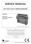
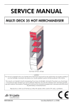
SERVICE MANUAL
HOT DELI 3/4/5/7 MERCHANDISERS
VERSIONS
Full service
Full service humidified
Self service
HD 5 full service on pedestal underframe
- NOTICE This manual is prepared for the use of trained Service Technicians and
should not be used by those not properly qualified. If you have attended
a trianing for this product, you may be qualified to perform all the procedures in this manual.
This manual is not intended to be all encompassing. If you have not
attended a training for this product, you should read, in its entirety, the
repair procedure you wish to performto determine if you have the necessary tools, instruments and skills required to perform the procedure.
Procedures for which you do not have the necessary tools, instruments
and skills should be performed by a trained technician.
Reproduction or other use of this Manual, without the express written
consent of Fri-Jado, is prohibited.
WWW.FRIJADO.COM
Service Manual Hot Deli HD3/4/5/7 form 9123549 rev.4/2007
Page 2
Service Manual Hot Deli HD3/4/5/7 form 9123549 rev.4/2007
TABLE OF CONTENTS
General technical data .................................................................................................... 4
Technical data .................................................................................................................................4
Programming instructions................................................................................................ 5
Removal and replacement of parts ................................................................................. 8
Panels left and right back side ...........................................................................................................8
Fuse and fuse holder ........................................................................................................................8
Contactor .........................................................................................................................................9
Water level control, electronic ............................................................................................................9
Blower, left hand side ........................................................................................................................9
Heating element, left hand side .......................................................................................................10
PT 1000 sensor ..............................................................................................................................10
Water level sensor ..........................................................................................................................11
Heating element water tray .............................................................................................................11
I/O Board ......................................................................................................................................12
Display board.................................................................................................................................12
Keypad ..........................................................................................................................................13
Thermostat Danfoss EKC 102A ........................................................................................................14
Sensor thermostat ...........................................................................................................................15
Tumble switch light and heating .......................................................................................................15
Blower right hand side ....................................................................................................................16
Heating element right hand side ......................................................................................................16
Drain .............................................................................................................................................17
Curved glass ..................................................................................................................................17
Curved glass (atlernative procedure when torques key is not available) ...................................18
Gas spring .....................................................................................................................................19
Lamp holder...................................................................................................................................19
Ceramic element ............................................................................................................................20
Blower in top ..................................................................................................................................21
Profile sliding door in top ................................................................................................................21
Protection profile in front (bumper) ..................................................................................................22
Side plate left and right, front side ...................................................................................................22
Electrical tests and service procedures ........................................................................... 23
PT 1000 sensor test ........................................................................................................................23
Heating element test .......................................................................................................................23
Adjusting Danfoss EKC 102A thermostat ..........................................................................................24
Danfoss EKC 102A Settings .............................................................................................................25
Control location full service and self service .....................................................................................26
Control panel humidified ................................................................................................................26
Troubleshooting ............................................................................................................ 27
Troubleshooting Hot Deli 3/4/5/7 full service & self service ...............................................................27
Troubleshooting Hot Deli 3/4/5/7 full service humidIfied ..................................................................28
Exploded views & partlists ............................................................................................. 29
Circuit diagrams ............................................................................................................ 42
Service Manual Hot Deli HD3/4/5/7 form 9123549 rev.4/2007
Page 3
GENERAL TECHNICAL DATA
GENERAL TECHNICAL DATA
This manual covers the Hot Deli Merchandisers. The Merchandisers come in 4 sizes to build-in into
an existing counter. Merchandisers will also be deliverd on a underframe.
The Merchandisers come in 3 versions.
• Full service with humidification.
• Full service.
• Self service.
All of the information, illustrations and specifications contained in this manual are based on the
latest product information available at the time of printing.
TECHNICAL DATA
Type
HD 3
HD 4
HD 5
HD 7
Power (W) Full service humidified
4600
4900
5100
8600
Power (W) Full Service
3700
4000
4200
7700
Power (W) Self Service
3700
4000
4200
-
Fuses needed with power connection
400V, 3N~50Hz (3 phases with zero)
3x 16 A
3x 16 A
3x 16 A
3x 16 A
Fuses needed with power connection
230V, 3~50Hz (3 phases without zero)
3x 20 A
3x 20 A
3x 20 A
3x 32 A
Fuses needed with power connection
230V, 1N~50Hz (1 phase with zero)
32 A
32 A
32 A
50 A
Standard plug from factory CEE-form
5-pole
16 A
16 A
16 A
16 A
Net weight full service, humidified (kg)
157
210
240
272
Net weight full service (kg)
142
195
225
257
Net weight self service (kg)
136
188
217
-
Gross weight full service, humidified
(kg)
212
275
315
355
Gross weight full service (kg)
197
260
300
340
Gross weight self service (kg)
191
253
292
-
Height (mm)
960
960
960
960
Width (mm)
1086
1419
1730
2505
Depth (mm)
1058
1058
1058
1058
Tools
• Standard set of tools.
• Metric wrenches, sockets and hex socket key wrenches.
• Multi meter and AC current clamp meter.
• Temperature tester.
• Insulation value tester (Megger).
• Field Service Grounding Kit.
Page 4
Service Manual Hot Deli HD3/4/5/7 form 9123549 rev.4/2007
PROGRAMMING INSTRUCTIONS
PROGRAMMING INSTRUCTIONS
DISPLAY SELF SERVICE AND SERVE OVER MODEL
Switch on
1. Switch on the heater with switch A6.
2. Switch on the lighting with switch A7.
3. Also switch on the IR emitters with switch A8
as required.
Switch off
1. Switch off the IR emitter with switch A8.
2. Switch off the lighting with switch A7.
3. Switch off the heating with switch A6.
Check set temperature
The temperature in the warmer is shown on display A2 during use.
1. Press centre key A4.
The set temperature will be shown on the display. The measured temperature in the warmer
will again be shown after 20 seconds.
Set the temperature
1. Press centre key A4. The set value will be
shown on the display.
2. Set the required temperature using the top
(A3) and bottom (A5) keys.
3. Press centre key A4 to save.
Service Manual Hot Deli HD3/4/5/7 form 9123549 rev.4/2007
Page 5
PROGRAMMING INSTRUCTIONS
DISPLAY HUMIDIFIED MODEL
Switch on
1. Keep keys B3 and B4 pressed simultaneously for 2 seconds.
2. Switch on the lighting with key B3.
3. Switch on the required IR emitters
with keys B1.
B1
B7
Switch off
1. Keep keys B3 and B5 pressed simultaneously for 2 seconds.
B8
B2
B3
B4
B5
B6
Check set temperature
The temperature in the warmer is shown on display B2 during use.
1. Press key B4 or B5 for a short time.
The set temperature will be shown on the display. The measured temperature in the warmer will
again be shown after 10 seconds.
Set the temperature
The temperature is set to 80°C and limited between 65°C and 90°C as standard.
1. Press key B4 or B5 for a short time. The set value will be shown on the display.
2. Wait 5 seconds; you cannot immediately change the setting.
3. Set the required temperature with keys B4 and B5.
4. Wait until the display again jumps to the measured temperature in the warmer. The adjustment
has now been saved.
Topping up the steam tray
You hear a signal as soon as the steam tray requires topping up. Humidification will be automatically switched off.
1. Press key B7 or B8 to stop the sound signal.
2. Fill the steam tray by three quarters (approx. 6,5 L.) with hot water to prevent large temperature
differences and severe steam occuring.
Humidification will be restarted automatically based on the previously set adjustment after topping
up. You do not have to set it again.
Page 6
Service Manual Hot Deli HD3/4/5/7 form 9123549 rev.4/2007
PROGRAMMING INSTRUCTIONS
DISPLAY HUMIDIFIED MODEL (CONTINUED)
Set the humidifier
Water consumption will amount to approx. 1.2 l per hour in relation to the maximum position.
Indication bar B6 displays the humidification degree.
• 3/3, humidification 100% switched on;
• 2/3, humidification 67% switched on;
• 1/3, humidification 33% switched on;
• 0, humidification switched off; the bottom segment of the indication bar will flash every 10 seconds.
1. Set the required humidification level with keys B7 and B8.
Set the IR emitters
1. Press keys B1 for a short time to switch on or off the related IR emitter. The indication light on top
of the key will light up if the emitter is switched on.
Service Manual Hot Deli HD3/4/5/7 form 9123549 rev.4/2007
Page 7
REMOVAL AND REPLACEMENT OF PARTS
REMOVAL AND REPLACEMENT OF PARTS
WARNING: Disconnect the electrical power to the machine at
the main circuit box. Place a tag on the circuit box indicating the
circuit is being serviced.
PANELS LEFT AND RIGHT BACK SIDE
1. Remove the socket screws that secure the
panel to the frame.
2. Turn panel towards yourself.
3. Reverse the procedure to install.
Note: The panels can be lifted out from the hinges. First lift out the hinge on the middle panel.
FUSE AND FUSE HOLDER
1. Remove the left side panel according prior
2.
3.
4.
5.
Page 8
procedure.
Remove the screws that secure the cover
plate and turn cover plate towards yourself.
Disconnect the wiring from the fuse housing.
Remove the flat nut that secures the housing
of the fuse and remove the housing.
Reverse the procedure to install.
Service Manual Hot Deli HD3/4/5/7 form 9123549 rev.4/2007
REMOVAL AND REPLACEMENT OF PARTS
CONTACTOR
1. Remove the left side panel and the cover
plate according prior procedure.
2. Disconnect the lead wires to the contactor.
3. Push down the locking tab and lift out to
remove the contactor from the mounting
bracket.
4. Reverse the procedure to install.
WATER LEVEL CONTROL, ELECTRONIC
1. Remove the left side panel and the cover
plate according prior procedure.
2. Disconnect the wiring of the electronic control.
3. Remove the 2 screws that secure the control
and remove the control.
4. Reverse the procedure to install.
BLOWER, LEFT HAND SIDE
1. Remove the left side panel and the cover
plate according prior procedure.
2. Remove the bolt that secures the electric
panel and remove this panel.
3. Cut the wiring of the blower.
4. Remove the nuts that secure the clamping
profiles on the blower and remover the profiles.
5. Remove the blower by sliding this towards
yourself.
6. Reverse the procedure to install.
Note: you have to connect the wiring again with
a butt splice.
Service Manual Hot Deli HD3/4/5/7 form 9123549 rev.4/2007
Page 9
REMOVAL AND REPLACEMENT OF PARTS
HEATING ELEMENT, LEFT HAND SIDE
1. Remove the left side panel and the cover
plate according prior procedure.
2. Disconnect the wiring from the element.
3. Remove the pans and frame out of the cabinet.
4. Remove the 2 nuts and rings that secure the
element and remove the element.
5. Reverse the procedure to install.
PT 1000 SENSOR
1. Remove the left side panel and the cover
plate according prior procedure.
2. Remove the bolt that secures the sensor and
remove the sensor.
3. Disconnect the wiring.
4. Reverse the procedure to install.
Page 10
Service Manual Hot Deli HD3/4/5/7 form 9123549 rev.4/2007
REMOVAL AND REPLACEMENT OF PARTS
WATER LEVEL SENSOR
1. Remove the left side panel and the cover
plate according prior procedure.
2. Remove the water tray door and the water
tray.
3. Disconnect the wiring of the sensor on the
electronic water level control (2 middle pins).
4. Remove the 2 nuts and socket screws that
secure the sensor bracket and remove the
sensor.
5. Reverse the procedure to install.
HEATING ELEMENT WATER TRAY
1. Remove the water tray door, the water tray
and the pans and frame inside the cabinet.
2. Remove the left and right hand panel on the
backside according prior procedures.
3. Disconnect the wiring from the elements.
4. Cut the sealant between cover housing and
the inside back plate in the cabinet.
5. Remove the 2 bolts that secure the cover
housing of the elements.
6. Slide the cover housing towards customer
side and lift it out.
7. Remove the nuts and rings that secure the
heating elements and remove the elements.
8. Reverse the procedure to install.
Note: Apply sealant between cover housing and
the inside back plate in the cabinet.
Service Manual Hot Deli HD3/4/5/7 form 9123549 rev.4/2007
Page 11
REMOVAL AND REPLACEMENT OF PARTS
I/O BOARD
1. Remove the right side panel according prior
procedure.
2. Remove the nuts that secure the cover plate
and remove the cover plate.
3. Disconnect all wiring and the flat cable.
4. Remove the board from the clips by pressing
the clips together.
5. Reverse the procedure to install.
DISPLAY BOARD
1. Remove the right side panel according prior
procedure.
2. Remove the nuts that secure the cover plate
and remove this plate.
3. Remove the nuts that secure the mounting
plate and remove this plate.
4. Disconnect the grey flat cable and the flat
cable from the keypad.
5. Remove the nuts that secure the board and
remove the board.
6. Reverse the procedure to install.
Note: When installing a new board, ensure that
the jumper on the new board is set the same as
on the old board (°C/°F).
jumper
Page 12
Service Manual Hot Deli HD3/4/5/7 form 9123549 rev.4/2007
REMOVAL AND REPLACEMENT OF PARTS
KEYPAD
1. Remove the right side panel according prior
procedure.
2. Remove the nuts that secure the cover plate
and remove this plate.
3. Remove the nuts that secure the mounting
plate and remove this plate.
4. Remove the grey flat cable and the flat cable
from the keypad.
5. Remove the nuts that secure the display
board and remove the board.
6. Remove the nut that secures the earth cable
on the panel and remove the cable.
7. Remove the back panel by lifting it out of the
hinges.
8. Remove the nut that secures the back plate of
the keypad and remove this plate.
9. Remove the keypad and clean the surface
with a degreaser.
10.Fasten the back plate back on the panel and
apply the keypad.
11.Apply acid free sealant around the green flat
cable.
12.Reverse the procedure to install.
Note: It is also possible to order a complete
back plate with keypad.
Service Manual Hot Deli HD3/4/5/7 form 9123549 rev.4/2007
Page 13
REMOVAL AND REPLACEMENT OF PARTS
THERMOSTAT DANFOSS EKC 102A
1. Remove the left and right hand panel according prior procedures.
2. Remove the left and right back panel by lifting them out of the hinges.
3. Remove the socket screws that secure the
middle panel and turn the panel towards
yourself.
4. Loosen the blocking clips on the sides of the
thermostat and remove the thermostat.
5. Disconnect the wiring.
6. Reverse the procedure to install.
Note: Set all parameters in the new thermostat.
Page 14
Service Manual Hot Deli HD3/4/5/7 form 9123549 rev.4/2007
REMOVAL AND REPLACEMENT OF PARTS
SENSOR THERMOSTAT
1. Remove the middle panel according prior
procedures.
2. Disconnect the wiring of the sensor on the
thermostat.
3. Remove the socket screws that secure the
sensor holder and remove the holder.
4. Remove sensor from holder.
5. Reverse the procedure to install.
TUMBLE SWITCH LIGHT AND HEATING
1. Remove the middle panel according prior
procedures.
2. Disconnect the wiring.
3. Remove the switch by pushing the clamps on
both sides.
4. Reverse the procedure to install.
Service Manual Hot Deli HD3/4/5/7 form 9123549 rev.4/2007
Page 15
REMOVAL AND REPLACEMENT OF PARTS
BLOWER RIGHT HAND SIDE
1. Remove the right side panel according prior
procedure.
2. Cut the wiring of the blower.
3. Remove the nuts that secure the clamping
profiles on the blower and remover the profiles.
4. Remove the blower by sliding this towards
yourself.
5. Reverse the procedure to install.
Note: you have to connect the wiring again with
a butt splice.
HEATING ELEMENT RIGHT HAND SIDE
1. Remove the right side panel according prior
procedure.
2. Disconnect the wiring from the element.
3. Remove the pans and frame out of the cabinet.
4. Remove the 2 nuts and rings that secure the
element and remove the element.
5. Reverse the procedure to install.
Page 16
Service Manual Hot Deli HD3/4/5/7 form 9123549 rev.4/2007
REMOVAL AND REPLACEMENT OF PARTS
DRAIN
1. Remove the pans and frame out of the cabinet.
2. Remove the nut inside the cabinet that secures the drain and remove the drain.
3. Reverse the procedure to install.
CURVED GLASS
1. Turn the curved glass to the top position.
2. Remove the cover plates on the mounting
profile (if necessary).
3. Loosen the adjusting screws that secure the
glass with the special torques key TX15.
4. Remove the curved glass.
5. Place the new glass with the plastic protection
profile.
6. Reverse the procedure to install.
Note 1: The cover plates are fixed with high temperature resistant sealant.
Note 2: Special torques key (TX15) is supplied
with the delivery of a new curved glass.
Service Manual Hot Deli HD3/4/5/7 form 9123549 rev.4/2007
Page 17
REMOVAL AND REPLACEMENT OF PARTS
CURVED GLASS (ATLERNATIVE PROCEDURE WHEN TORQUES KEY IS NOT AVAILABLE)
1. Turn curved glass to top position.
2. Remove the socket screws that secure the
reflector and turn the deflector downwards.
3. Remove on left and right top side the upper
bolts that secure the light fixture to the console.
4. Loosen the lower bolts on left and right top
side.
5. Turn the light fixture downwards, to create
extra space for a regular allen key or torques
key.
6. Loosen the adjusting screws that secure the
glass.
7. Remove the curved glass.
8. Place the new glass with the plastic protection
profile.
9. Reverse the procedure to install.
Page 18
Service Manual Hot Deli HD3/4/5/7 form 9123549 rev.4/2007
REMOVAL AND REPLACEMENT OF PARTS
GAS SPRING
1. Turn the curved glass to the top position.
2. Loosen the adjusting screw on the gas spring.
3. Remove the pin out of the gas spring. Be
aware of supporting the glass.
4. Remove the gas spring.
5. Reverse the procedure to install.
LAMP HOLDER
1. Remove the socket screws that secure the
reflector and turn the reflector downwards.
2. Remove the bolt that secures the protection
of the lamp and remove the protection.
3. Remove the bolt and nut that secures the
bracket on the lamp holder and remove the
bracket.
4. Disconnect the wiring.
5. Remove the screws that secure the lamp holder and remove the holder.
6. Reverse the procedure to install.
Service Manual Hot Deli HD3/4/5/7 form 9123549 rev.4/2007
Page 19
REMOVAL AND REPLACEMENT OF PARTS
CERAMIC ELEMENT
1. Remove the socket screws that secure the
reflector and turn the reflector downwards.
2. Remove the wiring from the element.
3. Remove the socket screws and nuts that secure the mounting plate of the elements and
lower this plate.
4. Remove the ceramic element from the plate
by sliding off the clip.
5. Reverse the procedure to install.
Page 20
Service Manual Hot Deli HD3/4/5/7 form 9123549 rev.4/2007
REMOVAL AND REPLACEMENT OF PARTS
BLOWER IN TOP
1. Remove the socket screws that secure the
reflector and turn the reflector downwards.
2. Slide the gasket from the wiring and cut the
wiring of the blower.
3. Remove the 4 socket screws that secure the
blower and remove the blower.
4. Reverse the procedure to install.
Note1: You have to tap 4x M5 thread in the new
blower housing.
Note2: You have to connect the wiring again
with a butt splice.
PROFILE SLIDING DOOR IN TOP
1. Remove the sliding doors.
2. Remove the socket screws that secure the
clamping profile and remove this profile
together with the profile of the sliding door.
3. Reverse the procedure to install.
Service Manual Hot Deli HD3/4/5/7 form 9123549 rev.4/2007
Page 21
REMOVAL AND REPLACEMENT OF PARTS
PROTECTION PROFILE IN FRONT (BUMPER)
1. Remove the profile with a screw driver. Slide
screw driver over the length to remove the
profile.
2. Install new profile.
SIDE PLATE LEFT AND RIGHT, FRONT SIDE
1. Remove the side glass.
2. Loosen the bolts on the bottom side that secure the side plate and remove this plate.
3. Loosen the bolts and rivets on the front
bottom side that secure the aluminium front
and remove this front.
4. Remove the side plate.
5. Reverse the procedure to install.
Page 22
Service Manual Hot Deli HD3/4/5/7 form 9123549 rev.4/2007
ELECTRICAL TESTS AND SERVICE PROCEDURES
ELECTRICAL TESTS AND SERVICE PROCEDURES
WARNING: Disconnect the electrical power to the machine at
the main circuit box. Place a tag on the circuit box indicating the
circuit is being serviced.
PT 1000 SENSOR TEST
1.
2.
3.
4.
Remove the right side panel according prior procedure.
Remove the wiring from the sensor.
Connect a temperature sensor to the probe for comparison.
Test the probe with an Ohmmeter.
Temperature
Resistance Ω
°F
± 5 Ohms
°C
60
16
1062
70
21
1082
80
27
1106
90
32
1124
100
38
1148
125
52
1202
150
65
1252
200
94
1362
250
121
1464
350
177
1674
450
233
1880
HEATING ELEMENT TEST
Note: When testing the resistance of the element remove the wiring.
Type
Wattage/Voltage
Resistance Ω
-5% + 10%
Current A
HD
All models
1500 / 230
35.3
6.5
1500 / 208
28.8
7.2
HD
Humidified
600 / 230
88.5
2.6
600 / 208
71.5
2.9
300 / 230
177.0
1.3
300 / 208
144.5
1.4
150 / 230
352.0
0.6
HD
All models
Service Manual Hot Deli HD3/4/5/7 form 9123549 rev.4/2007
Page 23
ELECTRICAL TESTS AND SERVICE PROCEDURES
ADJUSTING DANFOSS EKC 102A THERMOSTAT
In order to adjust the thermostat, first remove the thermostat according prior procedure.
Changing set point
1. Press the middle button until the temperature value is shown.
2. Change value with upper or lower button.
3. Press the middle button to confirm.
Setting internal parameters
1. Press the upper button for 3 seconds. In display the first parameter appears (ro1).
2. Press the middle button to read out value.
3. Change value with upper or lower button.
4. Press the middle button to confirm.
5. Press the lower button for the next parameter. Follow instructions 2 to 4.
When no key is pressed after last confirmation, system goes back to normal operation mode after
20 seconds.
Replacing of thermostat
When you install a new thermostat, then always change parameter r05 first to 0 (°C) and change
parameter o07 to HE. Otherwise some other parameters cannot be changed to the desired value.
You can run through the parameters with the up or down keys, once you are inside the parameter
settings.
Options
1. Return to factory settings. Turn the power off. Press and hold the upper and lower button and
switch the power on at the same time.
2. Actual temperature of sensor 1 (Thermostat). Press up key shortly 2 times.
Error codes on display
E1: Fault in controller.
E29: Cabinet sensor broken or wiring problem sensor.
Page 24
Service Manual Hot Deli HD3/4/5/7 form 9123549 rev.4/2007
ELECTRICAL TESTS AND SERVICE PROCEDURES
DANFOSS EKC 102A SETTINGS
DANFOSS EKC 102A
HD 3-4-5
Self service
HD 3-4-5-7
Full Service
Setpoint
°C
62,5
80
r01
Differential
°C
1
1
r02
Higher setpoint limit
°C
65
90
r03
Lower setpoint limit
°C
60
65
r04
Off-set temperature indication
°C
17,5
0
r05
Temperature unit (°C / °F)
°C
°C
°C
r09
Correction of signal from air output
°C
0
0
r12
Start / stop of temperature control
1
1
c01
Minimum “ON” time compressor
min
0
0
c02
Minimum “OFF” time compressor
min
0
0
c30
Reversed function of relay contact
OFF
OFF
d01
Defrost method (0=none)
0
0
d02
Defrost end temperature
°C
6
6
d03
Defrost interval
hour
8
8
d04
Maximum defrost time
min
45
45
d05
“ON” delay after defrost
min
0
0
d10
Defrost sensor (0=time, 1=air)
0
0
d13
Defrost at start up
no
no
o01
Output delay after start up
0
0
o05
Access code all settings
0
0
o06
Sensor type
ptc
ptc
o07
Warm (HE) / cold (rE)
HE
HE
o15
Step value display (yes = 0.5°C / no = 1°C)
no
no
o65
Store parameters under number
0
0
o66
Restore parameters as stored
0
0
o67
Store current parameter as factory default
OFF
OFF
u58
Status relay 1
-
-
Service Manual Hot Deli HD3/4/5/7 form 9123549 rev.4/2007
sec
Page 25
ELECTRICAL TESTS AND SERVICE PROCEDURES
CONTROL LOCATION FULL SERVICE AND SELF SERVICE
A1 Indicator ON
A2 Display temperature
A3 Up key
A4 SET key
A5 DOWN key
A6 Heating switch
A7 Lighting switch
A8 IR emitter switch
If the elements are switched on, the indicator
lamp A1 will go on.
CONTROL PANEL HUMIDIFIED
B1 IR emitter keys
B2 Temperature reading
B3 Lighting key
B4 Increase temperature
B5 Reduce temperature
B6 Humidification level reading
B7 Increase humidification
B8 Reduce humidification
The B1 keys switch the IR emitters in the light
cover individually. The sequence of the keys is the
same as the sequence of the emitters seen from
the operating side of the warmer.
Page 26
Service Manual Hot Deli HD3/4/5/7 form 9123549 rev.4/2007
TROUBLESHOOTING
TROUBLESHOOTING
TROUBLESHOOTING HOT DELI 3/4/5/7 FULL SERVICE & SELF SERVICE
Symptom
Possible causes
No power to warmer controls.
1. Main breaker open.
2. Fuse F1 burned.
3. Tumble switch heating malfunction.
4. Wiring loose.
No indication on electronic thermostat.
1. Tumble switch heating malfunction.
2. Fuse F1 burned.
3. Electronic thermostat malfunction.
4. Wiring loose.
Display does not reach desired temperature.
1. Incorrect line voltage.
2. PTC-1000 sensor malfunction.
3. Heater(s) inoperative.
4. Blower motor(s) inoperative.
5. Contactor inoperative.
6. Check parameters electronic thermostat.
Display temperature gets too high.
1. PTC-1000 sensor malfunction.
2. Contactor inoperative.
Ceramic element(s) do not work.
1. Tumble switch ceramics malfunction.
2. Ceramic element(s) inoperative.
3. Wiring loose.
No lighting.
1. Incorrect line voltage.
1. Tumble switch lighting malfunction.
3. Wiring loose.
4. Bad contact on lamp holders.
Service Manual Hot Deli HD3/4/5/7 form 9123549 rev.4/2007
Page 27
TROUBLESHOOTING
TROUBLESHOOTING HOT DELI 3/4/5/7 FULL SERVICE HUMIDIFIED
Symptom
Possible causes
No power to warmer controls.
1. Main breaker open.
2. Fuse F1 burned.
3. Wiring loose.
4. Loose flat cable display / I.O. board
Display does not reach desired temperature.
1. Incorrect line voltage.
2. PT-1000 sensor malfunction.
3. Heater(s) inoperative.
4. Blower motor(s) inoperative.
5. Relay on power and I/O board malfunction (x9)
6. Contactor inoperative.
7. Power and I/O board malfunction.
Display temperature gets too high.
1. PT-1000 sensor malfunction.
2. Contactor inoperative.
3. Power and I/O board malfunction.
Buzzer alarm sounds, but water tray is filled.
1. Scaling on water level sensor.
2. Electronic waterlevel control malfunction.
3. Wiring loose.
No heating of water tray.
1. Heater(s) inoperative.
2. Relay on power and I/O board malfunction (x11-x12)
3. Wiring loose.
Water keeps flowing.
1. Scaling on water level sensor.
2. Water level control malfunction.
3. Relay mafunction.
4. Solenoid water valve malfunction.
5. Too much pressure on water supply (valve does not close).
No water supply.
1. No pressure on water supply.
2. Water tube blocked.
3. Water level sensor malfunction.
4. Wiring loose.
5. Electronic water level control malfunction.
6. Relay mafunction.
7. Solenoid water valve malfunction.
No display and/or keypad does not function.
1. Loose flat cable display / I.O. board
2. Fuse F4 (125mA) burned
3. Fuse F1 or F2 burned.
4. Display and/or power and I/O board malfunction
No lighting.
1. Incorrect line voltage.
2. Relay on power and I/O board malfunction (x10)
3. Wiring loose.
4. Power and I/O board malfunction.
Products dry out too fast.
1. No water in watertray.
Page 28
Service Manual Hot Deli HD3/4/5/7 form 9123549 rev.4/2007
EXPLODED VIEWS AND PARTLISTS
EXPLODED VIEWS & PARTLISTS
Hot Deli 3-4-5 Self Service Assembly Drawing
Service Manual Hot Deli HD3/4/5/7 form 9123549 rev.4/2007
Page 29
EXPLODED VIEWS AND PARTLISTS
Hot Deli 3-4-5 Self Service Components Drawing
Page 30
Service Manual Hot Deli HD3/4/5/7 form 9123549 rev.4/2007
EXPLODED VIEWS AND PARTLISTS
Partlist Hot Deli 3-4-5 Self Service
Partlist Hot Deli 3-4-5 Self Service
Model
Item
Qty
Part number
Description
Model
Item
Qty
Part number
Description
HD 3
1
1
9262042
Glass, top
HD 3
29
1
9260420
Inner housing
HD 4
1
1
9262041
Glass, top
HD 4
29
1
9260415
Inner housing
HD 5
1
1
9262040
Glass, top
HD 5
29
1
9260410
Inner housing
HD 3
2
1
9263010
Mounting profile, glass
HD 3
30
1
9263040
Protection profile (plastic)
HD 4
2
1
9263005
Mounting profile, glass
HD 4
30
1
9263041
Protection profile (plastic)
HD 5
2
1
9263001
Mounting profile, glass
HD 5
30
1
9263042
Protection profile (plastic)
All models
3
9261027
Socket set screw M6x8, Torx,
stainless steel
All models
31
2
8071036
Plug, end
HD 3
32
1
9263045
Mounting profile
HD 4
32
1
9263046
Mounting profile
HD 5
32
1
9263047
Mounting profile
HD 3
33
1
9263013
Front, aluminium
HD 4
33
1
9263008
Front, aluminium
HD 5
33
1
9263004
Front, aluminium
All models
34
1
9264112
Side-plate, left front
All models
35
1
9264111
Side-plate, right front
All models
36
1
9264200
Cover plate, inner housing
HD 3
37
1
9262101
Lower window
All models
4
2
9262034
Cover plate
All models
5
2
4288324
Screw M 4x8, SS socket button
head
All models
6
1
9262022
Sideglass right
All models
7
1
9262023
Sideglass left
HD 3
8
1
9264071
Light fixture
HD 4
8
1
9264066
Light fixture
HD 5
8
1
9264057
Light fixture
All models
9
1
9261011
Blower
All models
10
8
4288322
Screw M5 x 10, SS socket
button head
HD 4
37
1
9262103
Lower window
All models
11
1
9264062
Profile, sideglass right
HD 5
37
1
9262105
Lower window
All models
12
1
9264063
Profile, sideglass left
HD 3
38
2
9263049
Protection profile (plastic)
All models
13
1
9262005
Console left, ass.
HD 4
38
2
9263055
Protection profile (plastic)
All models
14
1
9262004
Console right, ass.
HD 5
38
2
9263056
Protection profile (plastic)
All models
15
2
9241000
Bumper, console (20 pieces)
All models
39
1
9264204
Operation panel
HD 3
16
1
9261020
Gas spring 100 N
HD 3
40
3
9263030
Glass holder
HD 4
16
2
9261020
Gas spring 100 N
HD 4
40
4
9263030
Glass holder
HD 5
16
2
9261020
Gas spring 100 N
HD 5
40
5
9263030
Glass holder
41
1
3701067
Strain relief M32x1,5
HD 3
17
1
9264073
Clamping profile
All models
HD 4
17
1
9264068
Clamping profile
All models
42
1
3701068
Nut, relief strain M32x1,5
43
1
9070028
Connecting cable with plug
HD 5
17
1
9264059
Clamping profile
All models
HD 3
18
1
9262032
Profile, sliding door, top
All models
44
4
9181030
Adjustable leg
45
1
9264090
Cover profile, inner housing
HD 4
18
1
9262030
Profile, sliding door, top
HD 3
HD 5
18
1
9262028
Profile, sliding door, top
HD 4
45
1
9264085
Cover profile, inner housing
45
1
9264075
Cover profile, inner housing
HD 3
19
2
9262026
Glass, sliding door
HD 5
HD 4
19
2
9262025
Glass, sliding door
All models
46
1
9264084
Side-plate, left
HD 5
19
2
9262024
Glass, sliding door
All models
47
1
9264083
Side-plate, right
All models
20
2
8065038
Door handle
HD 3
48
1
9264091
Panel, service side
All models
21
2
9184253
Bumper profile
HD 4
48
1
9264086
Panel, service side
All models
22
2
9086207
Bumper
HD 5
48
1
9264076
Panel, service side
All models
23
4
0147674
Screw M 4x25, SS cross recess
head (philips)
HD 3
49
2
9260240
Back panel
HD 4
49
2
9260242
Back panel
HD 3
24
1
9262033
Profile, sliding door, bottom
HD 5
49
2
9260244
Back panel
HD 4
24
1
9262031
Profile, sliding door, bottom
HD 3
50
1
9264220
Plateau
HD 5
24
1
9262029
Profile, sliding door, bottom
HD 4
50
1
9264210
Plateau
HD 3
25
1
9264070
Holder, sliding door profile
HD 5
50
1
9264201
Plateau
HD 4
25
1
9264065
Holder, sliding door profile
All models
51
1
9265017
Side panel, left
HD 5
25
1
9264056
Holder, sliding door profile
All models
52
1
9265018
Side panel, right
HD 3
26
1
9264045
Airsuction profile
All models
53
2
9264000
Side panel, frame
HD 4
26
1
9264039
Airsuction profile
All models
54
1
9264002
Support
HD 5
26
1
9264022
Airsuction profile
HD 3
55
3
9264007
Support, frame
All models
27
2
9264017
Bracket, heating element
HD 4
55
3
9264005
Support, frame
All models
28
1
9264018
Support, tray frame
Service Manual Hot Deli HD3/4/5/7 form 9123549 rev.4/2007
Page 31
EXPLODED VIEWS AND PARTLISTS
Partlist Hot Deli 3-4-5 Self Service
Partlist Hot Deli 3-4-5 Self Service
Model
Item
Qty
Part number
Description
Model
Item
Qty
Part number
Description
HD 5
55
3
9264001
Support, frame
All models
104
2
9264020
Air deflector
HD 3
56
1
9264008
Cover plate
All models
105
6
3701027
Pop rivet 3,2 mm SS
HD 4
56
1
9264006
Cover plate
All models
106
1
9221011
Temperature sensor
HD 5
56
1
9264004
Cover plate
All models
107
1
9224121
Sensor holder
All models
57
1
9110810
Indication plate
All models
108
4
9264021
Clamping profile
HD 3
58
1.1
mtr
9261024
Protection profile (plastic)
All models
109
2
9053000
Blower
HD 4
58
1.5
mtr
9261024
Protection profile (plastic)
All models
110
1
9262070
Terminal block with bracket
All models
111
1
9044564
Connecting block, 1,2,3
HD 5
58
1.8
mtr
9261024
Protection profile (plastic)
All models
112
1
9044572
Connecting block, 4,5,6
All models
113
1
3500069
Contactor
HD 3
70
1
9264072
Reflector
All models
114
2
0141204
HD 4
70
1
9264067
Reflector
Screw M 4x16, SS cross recess
head (philips)
HD 5
70
1
9264058
Reflector
All models
115
2
0142307
Nut M 4 SS
HD 3
71
1
9265022
Mounting plate, ceramic
element
All models
116
1
9263020
Drain pipe
All models
117
1
9182065
Seal ring
HD 4
71
1
9265021
Mounting plate, ceramic
element
All models
118
1
9008542
Nut M 12 SS
HD 3
119
1
9260421
Air deflector
Mounting plate, ceramic
element
HD 4
119
1
9260416
Air deflector
HD 5
119
1
9260411
Air deflector
HD 5
71
1
9265020
HD 3
72
3
9181065
Heating element, Ceramic,
150 W
HD 3
120
1
9264044
Protection plate
HD 4
72
4
9181065
Heating element, Ceramic,
150 W
HD 4
120
1
9264038
Protection plate
HD 5
120
1
9264019
Protection plate
HD 5
72
5
9181065
Heating element, Ceramic,
150 W
All models
122
1
9264099
Fastening plate, fuse holder
HD 3
73
2
9262045
Protection, lamp
HD 4
73
3
9262045
Protection, lamp
HD 5
73
4
9262045
Protection, lamp
HD 3
74
2
9264060
Bracket, lamp holder
HD 4
74
3
9264060
Bracket, lamp holder
HD 5
74
4
9264060
Bracket, lamp holder
HD 3
75
2
9211016
Lamp holder
HD 4
75
3
9211016
Lamp holder
HD 5
75
4
9211016
Lamp holder
HD 3
76
2
9261002
Lamp, Halogen 100 W
HD 4
76
3
9261002
Lamp, Halogen 100 W
HD 5
76
4
9261002
Lamp, Halogen 100 W
All models
77
1
9221009
Thermostat, Danfoss
All models
78
1
9181008
Switch, tumble
All models
79
1
9181070
Sticker, upper heating
All models
80
1
9181071
Sticker, lighting
All models
81
1
9181072
Sticker, lower heating
All models
86
1
9264100
Mounting plate, electrical
components
All models
90
1
9264101
Cover plate, electric components
All models
91
2
0141204
Screw M 4x16, SS cross recess
head (philips)
All models
92
2
9261019
Fuse holder
All models
93
2
9261018
Fuse 6,3x32, ceramic T15A
All models
101
2
9182000
Heating element, 1500 W
All models
102
4
0169197
Gasket, heating element
All models
103
4
0169189
Nut, heating element
Page 32
Service Manual Hot Deli HD3/4/5/7 form 9123549 rev.4/2007
EXPLODED VIEWS AND PARTLISTS
Hot Deli 3-4-5 Full Service Assembly Drawing
Service Manual Hot Deli HD3/4/5/7 form 9123549 rev.4/2007
Page 33
EXPLODED VIEWS AND PARTLISTS
Hot Deli 3-4-5 Full Service Components Drawing
Page 34
Service Manual Hot Deli HD3/4/5/7 form 9123549 rev.4/2007
EXPLODED VIEWS AND PARTLISTS
Partlist Hot Deli 3-4-5 Full Service
Partlist Hot Deli 3-4-5 Full Service
Model
Item
Qty
Part number
Descirption
Model
Item
Qty
Part number
Descirption
HD 3
1
1
9260230
Glass, bended, complete with profiles
HD 5
19
2
9262024
Glass, sliding door
All models
20
2
8065038
Door handle
All models
21
2
9184253
Bumper profile
All models
22
2
9086207
Bumper
All models
23
4
0147674
Screw M 4x25, SS cross
recess head (philips)
HD 4
1
1
9260231
Glass, bended, complete with profiles
HD 5
1
1
9260232
Glass, bended, complete with profiles
HD 3
1-1
1
9262037
Glass, bended, without
profiles
HD 3
24
1
9262033
HD 4
1-1
1
9262036
Glass, bended, without
profiles
Profile, sliding door,
bottom
HD 4
24
1
9262031
HD 5
1-1
1
9262035
Glass, bended, without
profiles
Profile, sliding door,
bottom
HD 5
24
1
9262029
HD 3
1-2
1
9263011
Glass handle
Profile, sliding door,
bottom
HD 4
1-2
1
9263006
Glass handle
HD 3
25
1
9264070
Holder, sliding door
profile
HD 5
1-2
1
9263002
Glass handle
HD 4
25
1
9264065
HD 3
1-3
1.1 mtr
9261024
Protection profile
(plastic)
Holder, sliding door
profile
HD 5
25
1
9264056
HD 4
1-3
1.5 mtr
9261024
Protection profile
(plastic)
Holder, sliding door
profile
HD 3
26
1
9264045
Airsuction profile
HD 5
1-3
1.8 mtr
9261024
Protection profile
(plastic)
HD 4
26
1
9264039
Airsuction profile
HD 5
26
1
9264022
Airsuction profile
All models
27
2
9264017
Bracket, heating element
All models
28
1
9264018
Support, tray frame
HD 3
29
1
9260420
Inner housing
HD 4
29
1
9260415
Inner housing
HD 3
2
1
9263010
Mounting profile, glass
HD 4
2
1
9263005
Mounting profile, glass
HD 5
2
1
9263001
Mounting profile, glass
All models
3
9261027
Socket set screw M6x8,
Torx, stainless steel
All models
4
2
9262034
Cover plate
HD 5
29
1
9260410
Inner housing
All models
5
2
4288324
Screw M 4x8, SS socket
button head
HD 3
30
1
9263040
Protection profile
(plastic)
All models
6
1
9262022
Sideglass right
HD 4
30
1
9263041
All models
7
1
9262023
Sideglass left
Protection profile
(plastic)
HD 3
8
1
9264071
Light fixture
HD 5
30
1
9263042
Protection profile
(plastic)
HD 4
8
1
9264066
Light fixture
All models
31
2
8071036
Plug, end
HD 5
8
1
9264057
Light fixture
HD 3
32
1
9263045
Mounting profile
All models
9
1
9261011
Blower
HD 4
32
1
9263046
Mounting profile
All models
10
8
4288322
Screw M5 x 10, SS
socket button head
HD 5
32
1
9263047
Mounting profile
HD 3
33
1
9263012
Front, aluminium
HD 4
33
1
9263007
Front, aluminium
HD 5
33
1
9263003
Front, aluminium
All models
34
1
9264112
Side-plate, left front
All models
35
1
9264111
Side-plate, right front
All models
36
1
9264200
Cover plate, inner
housing
All models
39
1
9264204
Operation panel
All models
41
1
3701067
Strain relief M32x1,5
All models
42
1
3701068
Nut, relief strain
M32x1,5
All models
43
1
9070028
Connecting cable with
plug
All models
11
1
9264062
Profile, sideglass right
All models
12
1
9264063
Profile, sideglass left
All models
13
1
9262005
Console left, ass.
All models
14
1
9262004
Console right, ass.
All models
15
2
9241000
Bumper, console (20
pieces)
HD 3
16
2
8031843
Gas spring 500 N
HD 4
16
2
9261021
Gas spring 700 N
HD 5
16
2
8031819
Gas spring 850 N
HD 3
17
1
9264073
Clamping profile
HD 4
17
1
9264068
Clamping profile
HD 5
17
1
9264059
Clamping profile
HD 3
18
1
9262032
Profile, sliding door, top
All models
44
4
9181030
Adjustable leg
HD 4
18
1
9262030
Profile, sliding door, top
HD 3
45
1
9264090
HD 5
18
1
9262028
Profile, sliding door, top
Cover profile, inner
housing
HD 3
19
2
9262026
Glass, sliding door
HD 4
45
1
9264085
HD 4
19
2
9262025
Glass, sliding door
Cover profile, inner
housing
Service Manual Hot Deli HD3/4/5/7 form 9123549 rev.4/2007
Page 35
EXPLODED VIEWS AND PARTLISTS
Partlist Hot Deli 3-4-5 Full Service
Partlist Hot Deli 3-4-5 Full Service
Model
Item
Qty
Part number
Descirption
Model
Item
Qty
Part number
Descirption
HD 5
45
1
9264075
Cover profile, inner
housing
All models
81
1
9181072
Sticker, lower heating
HD 3
82
1
9264046
Exhaust profil
HD 4
82
1
9264040
Exhaust profil
HD 5
82
1
9264023
Exhaust profil
HD 3
83
3
9264025
Profile, tray frame, small
HD 4
83
4
9264025
Profile, tray frame, small
HD 5
83
5
9264025
Profile, tray frame, small
HD 3
84
2
9264024
Profile, tray frame, long
HD 4
84
3
9264024
Profile, tray frame, long
HD 5
84
4
9264024
Profile, tray frame, long
All models
86
1
9264100
Mounting plate, electrical components
All models
90
1
9264101
Cover plate, electric
components
All models
91
2
0141204
Screw M 4x16, SS cross
recess head (philips)
All models
92
2
9261019
Fuse holder
All models
93
2
9261018
Fuse 6,3x32, ceramic
T15A
All models
101
2
9182000
Heating element, 1500
W
All models
46
1
9264084
Side-plate, left
All models
47
1
9264083
Side-plate, right
HD 3
48
1
9264091
Panel, service side
HD 4
48
1
9264086
Panel, service side
HD 5
48
1
9264076
Panel, service side
HD 3
49
2
9260240
Back panel
HD 4
49
2
9260242
Back panel
HD 5
49
2
9260244
Back panel
All models
51
1
9265017
Side panel, left
All models
52
1
9265018
Side panel, right
All models
53
2
9264000
Side panel, frame
All models
54
1
9264002
Support
HD 3
55
3
9264007
Support, frame
HD 4
55
3
9264005
Support, frame
HD 5
55
3
9264001
Support, frame
HD 3
56
1
9264008
Cover plate
HD 4
56
1
9264006
Cover plate
HD 5
56
1
9264004
Cover plate
All models
57
1
9110810
Indication plate
All models
102
4
0169197
Gasket, heating element
HD 3
70
1
9264072
Reflector
All models
103
4
0169189
Nut, heating element
104
2
9264020
Air deflector
HD 4
70
1
9264067
Reflector
All models
HD 5
70
1
9264058
Reflector
All models
105
6
3701027
Pop rivet 3,2 mm SS
106
1
9221011
Temperature sensor
HD 3
71
1
9265022
Mounting plate, ceramic
element
All models
All models
108
4
9264021
Clamping profile
HD 4
71
1
9265021
Mounting plate, ceramic
element
All models
109
2
9053000
Blower
HD 5
71
1
9265020
Mounting plate, ceramic
element
All models
110
1
9262070
Terminal block with
bracket
HD 3
72
3
9181065
Heating element, Ceramic, 150 W
All models
111
1
9044564
Connecting block, 1,2,3
All models
112
1
9044572
Connecting block, 4,5,6
HD 4
72
4
9181065
Heating element, Ceramic, 150 W
All models
113
1
3500069
Contactor
All models
114
2
0141204
Heating element, Ceramic, 150 W
Screw M 4x16, SS cross
recess head (philips)
All models
115
2
0142307
Nut M 4 SS
HD 5
72
5
9181065
HD 3
73
2
9262045
Protection, lamp
All models
116
1
9263020
Drain pipe
HD 4
73
3
9262045
Protection, lamp
All models
117
1
9182065
Seal ring
HD 5
73
4
9262045
Protection, lamp
All models
118
1
9008542
Nut M 12 SS
HD 3
74
2
9264060
Bracket, lamp holder
HD 3
119
1
9260421
Air deflector
HD 4
74
3
9264060
Bracket, lamp holder
HD 4
119
1
9260416
Air deflector
HD 5
74
4
9264060
Bracket, lamp holder
HD 5
119
1
9260411
Air deflector
HD 3
75
2
9211016
Lamp holder
HD 3
120
1
9264044
Protection plate
HD 4
75
3
9211016
Lamp holder
HD 4
120
1
9264038
Protection plate
HD 5
75
4
9211016
Lamp holder
HD 5
120
1
9264019
Protection plate
HD 3
76
2
9261002
Lamp, Halogen 100 W
All models
122
1
9264099
HD 4
76
3
9261002
Lamp, Halogen 100 W
Fastening plate, fuse
holder
HD 5
76
4
9261002
Lamp, Halogen 100 W
All models
77
1
9221009
Thermostat, Danfoss
All models
78
1
9181008
Switch, tumble
All models
79
1
9181070
Sticker, upper heating
All models
80
1
9181071
Sticker, lighting
Page 36
Service Manual Hot Deli HD3/4/5/7 form 9123549 rev.4/2007
EXPLODED VIEWS AND PARTLISTS
Hot Deli 3-4-5 Full Service Humidified Assembly Drawing
Service Manual Hot Deli HD3/4/5/7 form 9123549 rev.4/2007
Page 37
EXPLODED VIEWS AND PARTLISTS
Hot Deli 3-4-5 Full Service Humidified Components Drawing
Page 38
Service Manual Hot Deli HD3/4/5/7 form 9123549 rev.4/2007
EXPLODED VIEWS AND PARTLISTS
Partlist Hot Deli 3-4-5 Full Service Humidified
Partlist Hot Deli 3-4-5 Full Service Humidified
Model
Item
Qty
Part number
Descirption
Model
Item
Qty
Part number
Descirption
HD 3
1
1
9260230
Glass, bended, complete with profiles
HD 5
19
2
9262024
Glass, sliding door
All models
20
2
8065038
Door handle
All models
21
2
9184253
Bumper profile
All models
22
2
9086207
Bumper
All models
23
4
0147674
Screw M 4x25, SS cross
recess head (philips)
HD 4
1
1
9260231
Glass, bended, complete with profiles
HD 5
1
1
9260232
Glass, bended, complete with profiles
HD 3
1-1
1
9262037
Glass, bended, without
profiles
HD 3
24
1
9262033
HD 4
1-1
1
9262036
Glass, bended, without
profiles
Profile, sliding door,
bottom
HD 4
24
1
9262031
HD 5
1-1
1
9262035
Glass, bended, without
profiles
Profile, sliding door,
bottom
HD 5
24
1
9262029
HD 3
1-2
1
9263011
Glass handle
Profile, sliding door,
bottom
HD 4
1-2
1
9263006
Glass handle
HD 3
25
1
9264070
Holder, sliding door
profile
HD 5
1-2
1
9263002
Glass handle
HD 4
25
1
9264065
HD 3
1-3
1.1 mtr
9261024
Protection profile
(plastic)
Holder, sliding door
profile
HD 5
25
1
9264056
HD 4
1-3
1.5 mtr
9261024
Protection profile
(plastic)
Holder, sliding door
profile
HD 3
26
1
9264045
Airsuction profile
HD 5
1-3
1.8 mtr
9261024
Protection profile
(plastic)
HD 4
26
1
9264039
Airsuction profile
HD 5
26
1
9264022
Airsuction profile
All models
27
2
9264017
Bracket, heating element
All models
28
1
9264018
Support, tray frame
HD 3
29
1
9260420
Inner housing
HD 4
29
1
9260415
Inner housing
HD 3
2
1
9263010
Mounting profile, glass
HD 4
2
1
9263005
Mounting profile, glass
HD 5
2
1
9263001
Mounting profile, glass
All models
3
9261027
Socket set screw M6x8,
Torx, stainless steel
All models
4
2
9262034
Cover plate
HD 5
29
1
9260410
Inner housing
All models
5
2
4288324
Screw M 4x8, SS socket
button head
HD 3
30
1
9263040
Protection profile
(plastic)
All models
6
1
9262022
Sideglass right
HD 4
30
1
9263041
All models
7
1
9262023
Sideglass left
Protection profile
(plastic)
HD 3
8
1
9264071
Light fixture
HD 5
30
1
9263042
Protection profile
(plastic)
HD 4
8
1
9264066
Light fixture
All models
31
2
8071036
Plug, end
HD 5
8
1
9264057
Light fixture
HD 3
32
1
9263045
Mounting profile
All models
9
1
9261011
Blower
HD 4
32
1
9263046
Mounting profile
All models
10
8
4288322
Screw M5 x 10, SS
socket button head
HD 5
32
1
9263047
Mounting profile
HD 3
33
1
9263012
Front, aluminium
HD 4
33
1
9263007
Front, aluminium
HD 5
33
1
9263003
Front, aluminium
All models
34
1
9264112
Side-plate, left front
All models
35
1
9264111
Side-plate, right front
All models
36
1
9260401
Water drawer
37
1
9262048
Water level sensor, ass.
All models
11
1
9264062
Profile, sideglass right
All models
12
1
9264063
Profile, sideglass left
All models
13
1
9262005
Console left, ass.
All models
14
1
9262004
Console right, ass.
All models
15
2
9241000
Bumper, console (20
pieces)
HD 3
16
2
8031843
Gas spring 500 N
All models
HD 4
16
2
9261021
Gas spring 700 N
All models
38
1
9260403
Middle section
HD 5
16
2
8031819
Gas spring 850 N
All models
39
1
9264078
Back panel, middle
HD 3
17
1
9264073
Clamping profile
All models
40
10
9087570
Nut M 5, serrated
HD 4
17
1
9264068
Clamping profile
All models
41
1
3701067
Strain relief M32x1,5
HD 5
17
1
9264059
Clamping profile
All models
42
1
3701068
HD 3
18
1
9262032
Profile, sliding door, top
Nut, relief strain
M32x1,5
HD 4
18
1
9262030
Profile, sliding door, top
All models
43
1
9070028
Connecting cable with
plug
HD 5
18
1
9262028
Profile, sliding door, top
All models
44
4
9181030
Adjustable leg
HD 3
19
2
9262026
Glass, sliding door
HD 3
45
1
9264090
HD 4
19
2
9262025
Glass, sliding door
Cover profile, inner
housing
Service Manual Hot Deli HD3/4/5/7 form 9123549 rev.4/2007
Page 39
EXPLODED VIEWS AND PARTLISTS
Partlist Hot Deli 3-4-5 Full Service Humidified
Partlist Hot Deli 3-4-5 Full Service Humidified
Model
Item
Qty
Part number
Descirption
Model
Item
Qty
Part number
Descirption
HD 4
45
1
9264085
Cover profile, inner
housing
HD 3
77
1
9260233
Keypad + backplate
HD 4
77
1
9260234
Keypad + backplate
HD 5
77
1
9260235
Keypad + backplate
HD 3
77-1
1
9262010
Keypad
HD 4
77-1
1
9262011
Keypad
HD 5
77-1
1
9262012
Keypad
All models
77-2
1
9264095
Backplate
All models
78
1
9262057
Display
All models
79
1
9262067
Power & I/O board
All models
80
1
9264081
Mounting plate
All models
81
1
9264082
Cover
HD 3
82
1
9264046
Exhaust profil
HD 4
82
1
9264040
Exhaust profil
HD 5
82
1
9264023
Exhaust profil
HD 3
83
3
9264025
Profile, tray frame, small
HD 4
83
4
9264025
Profile, tray frame, small
HD 5
83
5
9264025
Profile, tray frame, small
HD 3
84
2
9264024
Profile, tray frame, long
HD 4
84
3
9264024
Profile, tray frame, long
HD 5
84
4
9264024
Profile, tray frame, long
All models
85
1
9260404
Door, water drawer
All models
86
1
9264100
Mounting plate, electrical components
All models
87
1
9262072
Water level control,
electronic
All models
88
2
0141204
Screw M 4x16, SS cross
recess head (philips)
All models
89
2
9040659
Spacing pin, nylon
All models
90
1
9264101
Cover plate, electric
components
HD 5
45
1
9264075
Cover profile, inner
housing
All models
46
1
9264084
Side-plate, left
All models
47
1
9264083
Side-plate, right
HD 3
48
1
9264091
Panel, service side
HD 4
48
1
9264086
Panel, service side
HD 5
48
1
9264076
Panel, service side
HD 3
49
1
9260240
Back panel
HD 4
49
1
9260242
Back panel
HD 5
49
1
9260244
Back panel
HD 3
50
1
9260241
Back panel, right
HD 4
50
1
9260243
Back panel, right
HD 5
50
1
9260245
Back panel, right
All models
51
1
9265017
Side panel, left
All models
52
1
9265018
Side panel, right
All models
53
2
9264000
Side panel, frame
All models
54
1
9264002
Support
HD 3
55
3
9264007
Support, frame
HD 4
55
3
9264005
Support, frame
HD 5
55
3
9264001
Support, frame
HD 3
56
1
9264008
Cover plate
HD 4
56
1
9264006
Cover plate
HD 5
56
1
9264004
Cover plate
All models
57
1
9110810
Indication plate
HD 3
70
1
9264072
Reflector
HD 4
70
1
9264067
Reflector
HD 5
70
1
9264058
Reflector
HD 3
71
1
9265022
Mounting plate, ceramic
element
All models
91
2
0141204
HD 4
71
1
9265021
Mounting plate, ceramic
element
Screw M 4x16, SS cross
recess head (philips)
All models
92
2
9261019
Fuse holder
All models
93
2
9261018
Fuse 6,3x32, ceramic
T15A
All models
95
1
9260402
Cover, housing heating
elements
All models
96
1
9264030
End plate, water drawer
HD 5
71
1
9265020
Mounting plate, ceramic
element
HD 3
72
3
9181065
Heating element, Ceramic, 150 W
HD 4
72
4
9181065
Heating element, Ceramic, 150 W
All models
97
1
9264029
Cover plate
HD 5
72
5
9181065
Heating element, Ceramic, 150 W
All models
98
1
9264026
Housing, heating
elements
HD 3
73
2
9262045
Protection, lamp
All models
99
1
9182082
Heating element, 600 W
HD 4
73
3
9262045
Protection, lamp
All models
100
1
9182083
Heating element, 300 W
HD 5
73
4
9262045
Protection, lamp
All models
101
2
9182000
HD 3
74
2
9264060
Bracket, lamp holder
Heating element, 1500
W
HD 4
74
3
9264060
Bracket, lamp holder
All models
102
8
0169197
Gasket, heating element
HD 5
74
4
9264060
Bracket, lamp holder
All models
103
8
0169189
Nut, heating element
All models
104
2
9264020
Air deflector
All models
105
6
3701027
Pop rivet 3,2 mm SS
All models
106
1
9172310
Temperature sensor PT
1000
All models
107
2
0142307
Nut M 4 SS
All models
108
4
9264021
Clamping profile
HD 3
75
2
9211016
Lamp holder
HD 4
75
3
9211016
Lamp holder
HD 5
75
4
9211016
Lamp holder
HD 3
76
2
9261002
Lamp, Halogen 100 W
HD 4
76
3
9261002
Lamp, Halogen 100 W
HD 5
76
4
9261002
Lamp, Halogen 100 W
Page 40
Service Manual Hot Deli HD3/4/5/7 form 9123549 rev.4/2007
EXPLODED VIEWS AND PARTLISTS
Partlist Hot Deli 3-4-5 Full Service Humidified
Model
Item
Qty
Part number
Descirption
All models
109
2
9053000
Blower
All models
110
1
9262070
Terminal block with
bracket
All models
111
1
9044564
Connecting block, 1,2,3
All models
112
1
9044572
Connecting block, 4,5,6
All models
113
1
3500069
Contactor
All models
114
2
0141204
Screw M 4x16, SS cross
recess head (philips)
All models
115
2
0142307
Nut M 4 SS
All models
116
1
9263020
Drain pipe
All models
117
1
9182065
Seal ring
All models
118
1
9008542
Nut M 12 SS
HD 3
119
1
9260421
Air deflector
HD 4
119
1
9260416
Air deflector
HD 5
119
1
9260411
Air deflector
HD 3
120
1
9264044
Protection plate
HD 4
120
1
9264038
Protection plate
HD 5
120
1
9264019
Protection plate
All models
121
1
9262027
Flatcable
All models
122
1
9264099
Fastening plate, fuse
holder
Service Manual Hot Deli HD3/4/5/7 form 9123549 rev.4/2007
Page 41
CIRCUIT DIAGRAMS
CIRCUIT DIAGRAMS
Page 42
Service Manual Hot Deli HD3/4/5/7 form 9123549 rev.4/2007
CIRCUIT DIAGRAMS
Service Manual Hot Deli HD3/4/5/7 form 9123549 rev.4/2007
Page 43
Page 44
0
1/3
2/3
3/3
CIRCUIT DIAGRAMS
Service Manual Hot Deli HD3/4/5/7 form 9123549 rev.4/2007
0
1/3
2/3
3/3
CIRCUIT DIAGRAMS
Service Manual Hot Deli HD3/4/5/7 form 9123549 rev.4/2007
Page 45
Page 46
0
1/3
2/3
3/3
CIRCUIT DIAGRAMS
Service Manual Hot Deli HD3/4/5/7 form 9123549 rev.4/2007
0
1/3
2/3
3/3
CIRCUIT DIAGRAMS
Service Manual Hot Deli HD3/4/5/7 form 9123549 rev.4/2007
Page 47
CIRCUIT DIAGRAMS
Page 48
Service Manual Hot Deli HD3/4/5/7 form 9123549 rev.4/2007
CIRCUIT DIAGRAMS
Service Manual Hot Deli HD3/4/5/7 form 9123549 rev.4/2007
Page 49
Page 50
0
1/3
2/3
3/3
CIRCUIT DIAGRAMS
Service Manual Hot Deli HD3/4/5/7 form 9123549 rev.4/2007
0
1/3
2/3
3/3
CIRCUIT DIAGRAMS
Service Manual Hot Deli HD3/4/5/7 form 9123549 rev.4/2007
Page 51
Page 52
0
1/3
2/3
3/3
CIRCUIT DIAGRAMS
Service Manual Hot Deli HD3/4/5/7 form 9123549 rev.4/2007
0
1/3
2/3
3/3
CIRCUIT DIAGRAMS
Service Manual Hot Deli HD3/4/5/7 form 9123549 rev.4/2007
Page 53
CIRCUIT DIAGRAMS
Page 54
Service Manual Hot Deli HD3/4/5/7 form 9123549 rev.4/2007
CIRCUIT DIAGRAMS
Service Manual Hot Deli HD3/4/5/7 form 9123549 rev.4/2007
Page 55
Page 56
0
1/3
2/3
3/3
CIRCUIT DIAGRAMS
Service Manual Hot Deli HD3/4/5/7 form 9123549 rev.4/2007
0
1/3
2/3
3/3
CIRCUIT DIAGRAMS
Service Manual Hot Deli HD3/4/5/7 form 9123549 rev.4/2007
Page 57
Page 58
0
1/3
2/3
3/3
CIRCUIT DIAGRAMS
Service Manual Hot Deli HD3/4/5/7 form 9123549 rev.4/2007
0
1/3
2/3
3/3
CIRCUIT DIAGRAMS
Service Manual Hot Deli HD3/4/5/7 form 9123549 rev.4/2007
Page 59
Page 60
0
1/3
2/3
3/3
CIRCUIT DIAGRAMS
Service Manual Hot Deli HD3/4/5/7 form 9123549 rev.4/2007
Service Manual Hot Deli HD3/4/5/7 form 9123549 rev.4/2007
0
1/3
2/3
3/3
CIRCUIT DIAGRAMS
Page 61
Page 62
0
1/3
2/3
3/3
CIRCUIT DIAGRAMS
Service Manual Hot Deli HD3/4/5/7 form 9123549 rev.4/2007
Service Manual Hot Deli HD3/4/5/7 form 9123549 rev.4/2007
0
1/3
2/3
3/3
CIRCUIT DIAGRAMS
Page 63
Fri-Jado B.V. • P.O. Box 560 • 4870 AN • Etten-Leur • The Netherlands • tel +31 76 50 85 400 • fax +31 76 50 85 444 • [email protected] • www.frijado.com
Service Manual Hot Deli HD3/4/5/7 form 9123549 rev.4/2007