1
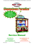
To Purchase This Item, Visit BMI Gaming | www.bmigaming.com | (800) 746-2255 | +1.561.391.7200
≡ SPEED DEMON™ ≡
OWNER’S MANUAL
Version 1.09
Version 1.04.05DB
Version 1.07.01
January 2006
BAY TEK GAMES, INC.
1077 East Glenbrook Drive
Pulaski, WI 54162
E-mail: [email protected]
Web site: www.baytekgames.com
Service:
(920) 822-3951 ext. 1102
Parts: ......... (920) 822-3951 ext. 1101
Fax: ...........................(920) 822-8936
Service Fax: ...............(920) 822-1496
Sales: ........................(920) 822-3951
To Purchase This Item, Visit BMI Gaming | www.bmigaming.com | (800) 746-2255 | +1.561.391.7200
TABLE OF CONTENTS
Safety Precautions .................................1
How the Game Works ............................1
Service Connections ..............................2
Unpacking, Assembly and Installation....2
Alarm/Sounds.........................................3
Counters.................................................3
Input Section B – Inputs RE, RC.......... 23
Output Section A – Chase Lights, Q13 Q16 ...................................................... 24
Output Section B – Q17 – Q24 ............ 25
Output Section C – Q5 – Q12 .............. 26
Power Section...................................... 27
Processor Section – Input RD.............. 28
PROGRAMMING SECTION......................4
SPARE PARTS – SPEED DEMON......... 29
Programmable Options ..........................4
Group #1 (S1) .....................................4
Group #2 (S2) .....................................6
TECHNICAL SUPPORT ......................... 31
OPERATION AND SETUP SECTION .......1
PREVENTIVE MAINTENANCE SECTION 7
Maintenance Chart .................................7
TROUBLESHOOTING & DIAGNOSTICS
SECTION...................................................8
Troubleshooting Strategy .......................9
Diagnose Power Supply .......................10
SERVICE AND REPAIR SECTION .........11
Access to the playfield..........................11
Removal of the Playfield.......................11
Turntable Motor Replacement ..............11
Turntable Position Sensor Replacement
.............................................................12
Ball Shoot Solenoid Replacement ........12
Circuit boards .......................................13
Bonus Tickets Display Circuit Board.13
Ball Drop Sensor Circuit Board .........14
Main Circuit Board ............................14
ELECTRICAL DRAWINGS SECTION ....16
12 Volt Jumper Cable (J1) Connector ..16
Volume Cable (J2) Connector ..............16
Sensor Cable (J3) Connector...............17
Jumper (J4) Connector.........................18
Jumper (J5) Connector.........................19
Gen 5 Main Board Schematics.............20
Communications – Serial EEprom........21
Input Section A – Configuration Switches
.............................................................22
Speed Demon™
OPTIONAL TICKET PATTERNS............ 32
WARRANTY INFORMATION ................. 34
REPAIR RECORD .................................. 35
NOTES .................................................... 36
To Purchase This Item, Visit BMI Gaming | www.bmigaming.com | (800) 746-2255 | +1.561.391.7200
OPERATION AND SETUP SECTION
Safety Precautions
How the Game Works
CAUTION: Electrical Shock
Hazard.
Do not perform repairs or
maintenance on this game
with power ON. Unplug the
unit from the wall outlet or shut off power at
the power strip inside the cabinet.
A simple game with a winner every time, but a
hard game to master for bonus tickets. The
player, using a pinball type shooter, shoots a
small ball up into a rotating nine hole disk in the
playfield. See figure 1. If the ball drops into one
of the six ticket winning holes, the player is
immediately rewarded with that number of
tickets. If the ball drops into one of the three
‘Speed Demon’ holes, the upper bonus wheel
comes into play.
CAUTION: Electrical Shock
Hazard.
Always plug game into a
grounded circuit.
CAUTION: Cutting Hazard.
Always replace broken or
scratched glass panels with
tempered glass. Never use
window glass in this game.
CAUTION: Use of flammable
substances can cause severe
burns or personal injury.
Always use non-flammable
solvents for cleaning parts and
surfaces of this game. Do not use flammable
substances such as gasoline, kerosene or
thinners.
Figure 2 Speed Demon Game
Figure 1 Demon’s Turntable
Speed Demon™
The bonus wheel is comprised of three rings,
each divided into segments with bonus ticket
values, and a center jackpot ‘Win Tickets’
display that increments with each game played.
During bonus play, the object for the player is to
step up through the bonus rings to win the
jackpot. The player must hit the ‘Stop’ button at
1
To Purchase This Item, Visit BMI Gaming | www.bmigaming.com | (800) 746-2255 | +1.561.391.7200
just the right time to stop the rotating light on a
red ‘demon’ arrow that takes them to the next
level. Stopping on any other ring segment ends
the game and dispenses tickets based on that
segment value.
2. Place the game near the final location and
remove the keys taped in the coin return and
open the rear door panel.
POWER SUPPLY
For multiple games set up for progressive play,
the progressive display and each game’s ‘Win
Ticket‘ display would be the same value.
220V TRANSFORMER
AND FUSE
The bonus ring ticket counts can be changed as
well as the jackpot settings. See programming
section on page 4 for more details.
Tickets are dispensed as they are won. If the
ticket dispenser runs out of tickets, the payout
will continue after the dispenser is refilled.
Service Connections
All Bay Tek games are 110V or 220V(optional)
and draw 2-3 amps at startup. Outlets should
be rated for 20 amps or higher.
IMPORTANT: Be sure that the electrical power
outlets match the game requirements. See
outlet labeling at rear bottom of game cabinet.
Unpacking, Assembly and
Installation
1. Inspect the game for any damaged, loose or
missing parts. If damage is found please
contact the carrier first. Then contact Bay Tek
at: [email protected], or phone (920)
822-3951 to order replacement parts.
CAUTION:
Lifting
Hazard.
Lifting heavy objects can cause
back, neck and other injuries.
Be sure adequate lifting and
moving devices are available
when unloading, unpacking and moving this
game.
CIRCUIT BREAKER
Figure 3 Power Supply with optional 220V setup.
3. Uncoil the power cord and feed the cord
through one of the holes in the bottom board at
the back of the cabinet. Plug the power cord
into the wall outlet.
4. Place the game in its final position. The
game must be reasonably level to insure proper
ball action. If leveling is necessary, use
adequate shims and blocking to prevent the
game from tipping.
5. Open the front access door and disconnect
the ‘Stop’ button wiring. Release the two toggle
latches securing the ‘Stop’ button panel. Slide
the top glass downward out of the cabinet.
6. Place the two balls, shipped with the game,
into any hole in the turntable. The game does
not have to have power on. Replace the top
glass and ‘Stop’ button access panel.
7. Turn power ON at the power strip located
inside the cabinet at the bottom of the rear
panel. The turntable should start to rotate
within a few seconds.
8. Fill the ticket tray inside the cabinets. The
Win Tickets display will show the letters ‘Lo’ to
indicate when the level of the tickets drops to
approximately 1/2 inch high.
9. Play the game a few times to make sure
that everything is working. (For testing, open
Speed Demon™
2
To Purchase This Item, Visit BMI Gaming | www.bmigaming.com | (800) 746-2255 | +1.561.391.7200
the front panel and trip one of the coin count
wires a few times to establish game credits). If
something is not working properly, review the
troubleshooting section first. If the problem
cannot be resolved, contact the Bay Tek
service
department
at:
[email protected], or phone (920)
822-3951.
10. Once everything is set and working
properly, close and lock the front panel. Use
glass cleaner and a soft clean cloth to clean all
the glass on the game. Do not use solvents to
clean the game decal surfaces. The game is
now ready to play.
Alarm/Sounds
A voice chip enhances the visual effects of the
game during normal play and during ‘Attract”
mode of operation. A volume control is located
on the front door panel.
VOLUME CONTROL
JACKPOT RESET
COUNTERS
Figure 4 Game Controls
Counters
Counters are mounted inside the cabinet on the
front door panel. The counters track the number
of games played and tickets dispensed. The
counters cannot be reset.
Speed Demon™
3
To Purchase This Item, Visit BMI Gaming | www.bmigaming.com | (800) 746-2255 | +1.561.391.7200
PROGRAMMING SECTION
The ticket patterns, bonus ring settings, coins per
play, attract mode and more are controlled by
dipswitches located on the main circuit board.
See instructions below for details.
Programmable Options
The main circuit board is located on the inside
wall of the cabinet with access through the rear
door. Be sure power is off before setting these
dipswitches.
IMPORTANT: Power must be OFF to the game
when setting dipswitches. Turn OFF the power
strip inside the cabinet. Set the dipswitches to the
desired settings, wait 30 seconds and then turn
ON power at the power strip.
Figure 5 Dipswitch Locations on Main Circuit
Board
Group #1 (S1)
MAIN BOARD
S1
ON
1 2 3 4 5 6 7 8
ON
S
1 2 3 4 5 6 7 8
* - indicates the default setting
TICKET PATTERN
PATTERN #
SWITCH #
1
2
3
OFF
OFF
OFF
1*
OFF
OFF
ON
2
OFF
ON
OFF
3
OFF
ON
ON
4
ON
OFF
OFF
5
ON
OFF
ON
6
ON
ON
OFF
7
ON
ON
ON
8
Speed Demon™
DESCRIPTION
S1
ON
1 2 3
Dipswitches # 1, # 2 and # 3 (S1) are used to set the
ticket pattern number. The ticket pattern number
determines the number of tickets dispensed for each
segment on the three bonus rings. Changing these
settings also required changing the ring display.**
* The setting to the left shows the default ticket pattern
number of 1 that corresponds to the ticket count on the
rings as shipped from the factory.
**Additional patterns are shown at the end of this
manual, see page 32, and are available by contacting
Bay Tek.
4
To Purchase This Item, Visit BMI Gaming | www.bmigaming.com | (800) 746-2255 | +1.561.391.7200
BONUS SPEED RING SETTINGS
SWITCH #
4
SPEED
DESCRIPTION
5
S1
OFF
OFF
SLOW (easy)
OFF
ON
FAST
ON
OFF
FASTER *
ON
ON
FASTEST
ON
1 2 3 4 5
Dipswitches #4 and #5 (S1) are used to set
the speed of the revolving light on the bonus
ring during bonus play. The ‘Slow’ speed is
the easiest. * The drawing to the left shows
the default factory setting of ‘Fast’.
COINS PER PLAY
SWITCH #
COINS
6
DESCRIPTION
S1
ON
2
OFF
1*
ON
1 2 3 4 5 6
Dipswitch #6 (S1) is used to set the number of coins
needed for each ball to be played. * The drawing to the
left shows the default factory setting of ‘1’.
ATTRACT MODE
SWITCH #
ATTRACT
7
DESCRIPTION
S1
ON
Enable *
OFF
Disable
ON
1 2 3 4 5 6 7
When dipswitch # 7 (S1) is enabled, the game will
start to run in ‘Attract’ for a short time every 3 minutes.
During the ‘Attract’ mode, the attraction lighting will
light up, and the audio will play select tracks from the
audio bank embedded in the software. * The drawing
to the left shows the default factory setting of ‘enable’.
JACKPOT INCREMENT PER GAME
SWITCH #
VALUE
8
DESCRIPTION
S1
ON
1 *
OFF
0
Speed Demon™
ON
1 2
3 4 5 6 7
8
Dipswitch # 8 (S1) is used to set the jackpot
(Win Tickets display) increment for each play to
1 or zero (no incrementing. If no incrementing is
set, the default ticket value is the ‘Jackpot
Maximum’ as set on dipswitches #6, #7 and #8
(S2) below. * The drawing to the left shows the
default factory setting of 1 increment for each
coin played.
5
To Purchase This Item, Visit BMI Gaming | www.bmigaming.com | (800) 746-2255 | +1.561.391.7200
Group #2 (S2)
MAIN BOARD
S1
ON
1 2 3 4 5 6 7 8
FU
1 2 3 4 5 6 7 8
ON
MERCY TICKET VALUE ON WHEEL
SWITCH
1
VALUE
DESCRIPTION
2
OFF
OFF
1
OFF
ON
2
ON
OFF
3*
ON
ON
4
Dipswitches #1 and #2 (S2) are used to set the value of the six ticket
winning holes in the rotating turntable. * The drawing to the left shows
the default factory setting of ‘3’ tickets per hole.
S1
ON
1
2
JACKPOT MINIMUM TICKET PAYOUT
SWITCH #
3
OFF
OFF
OFF
OFF
ON
ON
ON
ON
4
OFF
OFF
ON
ON
OFF
OFF
ON
ON
5
OFF
ON
OFF
ON
OFF
ON
OFF
ON
VALUE
50
100
150
200
250 *
300
400
500
DESCRIPTION
S1
ON
1 2
3 4 5
Dipswitches #3, #4 and #5 (S2) are used to set the
minimum number of jackpot tickets dispensed. This
is the starting ticket value for jackpot and
progressive displays. * The drawing to the left
shows the default factory setting of 250 tickets
minimum.
JACKPOT MAXIMUM TICKET PAYOUT
SWITCH #
6
OFF
OFF
OFF
OFF
ON
ON
ON
ON
7
OFF
OFF
ON
ON
OFF
OFF
ON
ON
8
OFF
ON
OFF
ON
OFF
ON
OFF
ON
Speed Demon™
VALUE
100
200
300
400
500
600
750
1000 *
DESCRIPTION
S1
ON
1
2 3 4 5 6 7
8
Dipswitches #3, #4 and #5 (S2) are used to
set the maximum number of jackpot tickets
dispensed for jackpot and progressive
displays. * The drawing to the left shows
the default factory setting of 1000 tickets
maximum.
6
To Purchase This Item, Visit BMI Gaming | www.bmigaming.com | (800) 746-2255 | +1.561.391.7200
PREVENTIVE MAINTENANCE SECTION
Maintenance Chart
Use the following maintenance chart as a guide
only. Actual maintenance intervals will depend
on usage and environmental conditions at the
location of the game.
Keep a log of all inspections, even if no problem
exists, with date and time of inspection, action
taken. A sample Repair Record form is included
at the end of this manual.
IMPORTANT: The game should be shut OFF
for cleaning and maintenance.
CAUTION: Use of flammable
substances can cause severe
burns or personal injury.
Always
use
non-flammable
solvents for cleaning parts and surfaces of
this game. Do not use flammable
substances such as gasoline, kerosene or
thinners.
IMPORTANT: Do not use cleaning solvents on
game graphics. Use only a mild soap solution
and dry with a clean lint free cloth.
Daily
Inspect game for physical damage. Repair as necessary.
X
Check all game lighting. Repair/replace lamps as necessary.
X
Clean outside surfaces with warm soapy water only. Do not
use solvents on decals or Acrylic™ surfaces.
X
Fill ticket tray.
X
Empty coin tray.
X
Test game to insure proper operation.
X
Open game and clean playfield and inner surfaces with a
clean soft cloth and glass cleaner. **Insure there is no dirt or
debris in the ball chute or on the edges of the ball guides.
Blow paper dust from ticket mechanism. Clean more often if
game is used extensively or conditions dictate cleaning
sooner.
Weekly
Monthly
X
X
Lubricate plunger with light machine oil.
X
Check all fasteners for tightness
X
The stepper motor and associated gearing DO NOT require
any lubrication.
Speed Demon™
7
To Purchase This Item, Visit BMI Gaming | www.bmigaming.com | (800) 746-2255 | +1.561.391.7200
TROUBLESHOOTING & DIAGNOSTICS SECTION
Troubleshooting Chart
Problem
Probable Cause
Remedy
Unplugged.
Blown fuse
Circuit breaker tripped.
Bad power supply.
a. Check wall outlet.
b. Check transformer fuse (220v
applications only).
c. Reset power strip breaker switch or
building circuit breaker.
d. See power supply diagnostic on page
10.
a. Increase the volume at the volume
control at the inside of the front door
panel.
b. Check audio cable connections to
speaker, volume control and main
circuit board.
c. Replace main board with board from
another Gen 5 game if possible to
isolate the problem to the main circuit
board.
No power to the game.
a.
b.
c.
d.
No Audio
a. Volume too low.
b. Loose wire.
c. Main circuit board
malfunction.
Demon wheel slips or
does not rotate.
a. Faulty wheel motor.
b. Alignment problem or
broken gear teeth.
c. Bad Wiring.
Ball does not position at
plunger when coin is
inserted.
a. Fuse blown.
b. Faulty solenoid used to
push ball into position.
c. Bad Wiring
Wheel doesn’t score
properly.
a. Bad turntable position
sensor.
b. Bad wiring.
a. Faulty button switch.
b. Bad Wiring
Rotating bonus light
doesn’t stop when
button is pushed.
Lighting not functioning
properly.
Bonus
Ticket Display
Fluorescent
Speed Demon™
a. Burned out lamps.
b. Cable problem.
c. Bad circuit board – bad
LED’s
d. Main circuit board
malfunction.
a. Replace stepper motor.
b. Remove play in gears by sliding motor
in bracket towards small gear and
tighten in place. Replace gear(s).
c. Check continuity of wire from motor to
main board.
a. Replace fuse on circuit board behind
the solenoid mounting board. See
b. Replace solenoid.
c. Check continuity of wire from solenoid
to main board.
a. Replace the position sensor.
b. Check continuity of wire from motor to
main board.
a. Replace button switch.
b. Check continuity of wire from button
switch to main board.
a. Replace lamps.
b. Check and repair cable to main board.
c. Replace faulty circuit board.
d. Replace main board with a spare Gen
5 board if possible to isolate the
problem to the main circuit board.
8
To Purchase This Item, Visit BMI Gaming | www.bmigaming.com | (800) 746-2255 | +1.561.391.7200
Troubleshooting Chart
Problem
Probable Cause
Remedy
Tickets do not dispense.
a. Ticket tray empty. Faulty
low ticket sensor switch.
b. Sensor switch stuck or
switch wire bent out of
position.
c. Faulty cable to dispenser.
d. Dirty opto-sensor or paper
dust buildup in ticket
dispenser.
e. Ticket dispenser not
working.
f. Main circuit board
malfunction.
Wrong number of tickets
dispensed.
a. Ticket Pattern or other
ticket dipswitches set
wrong.
b. Dirty opto-sensor on ticket
dispenser.
c. Faulty ticket dispenser.
d. Main circuit board
malfunction.
a. Fill ticket tray. Replace low ticket
sensor switch.
b. Clean ticket tray of dirt and loose
tickets or debris. Bend switch wire to
correct position under tickets.
c. Check wiring continuity from
dispenser to main board. Check for
pinched, broken or disconnected
cable. Replace as necessary.
d. Clean with compressed air and if
necessary wipe sensor with isopropyl
alcohol on a cotton swab.
e. Replace dispenser with spare working
dispenser.
f. Replace main board with a spare Gen
5 board if possible to isolate the
problem to the main circuit board.
a. Check and reset dipswitches for
proper setting.
b. Clean with compressed air and if
necessary wipe with isopropyl alcohol
on a cotton swab.
c. Replace with spare working
dispenser.
d. Replace main board with a spare Gen
5 board if possible to isolate the
problem to the main circuit board.
Troubleshooting Strategy
Use common sense and a systematic method
of troubleshooting to determine the exact
problem, probable cause and remedy. Use the
process of elimination to find the faulty
component. Always check for the simple and
obvious causes first such as unplugged, loose
or broken wires, bad sensors, blown fuses,
bent, pinched, stuck or jammed components.
FUSE
Figure 6 Ball Shooter Solenoid Fuse (access
from rear door)
Use 2 amp, 250V (5 x 20mm) fuse (p/n
A5FUSE3).
Speed Demon™
9
To Purchase This Item, Visit BMI Gaming | www.bmigaming.com | (800) 746-2255 | +1.561.391.7200
Diagnose Power Supply
Use the following procedure to check the power
supply for Gen 5 games.
12 V OUT
Check the small green LED light on the power
supply circuit board. If the light is out there is a
short somewhere. If the light dims, there is an
overload in one of the circuits such as a bad
motor.
Turn power OFF. Disconnect all 12 volt
output wires only. Turn power ON.
Green LED Light
comes ON.
Figure 7 Power Supply
Green LED Light
remains OFF.
Replace Power
Supply.
Turn power OFF. Unplug all outputs from the Gen 5 Circuit Board.
Reconnect the 12 volt output wires to the Power Supply. Turn power
ON.
Green LED Light
comes ON.
Turn power OFF.
Reconnect the outputs
at the Main Circuit
Board one at a time.
Wait 3 minutes
between tests to turn
power ON.
Green LED Light
comes ON.
Speed Demon™
Green LED Light
remains OFF.
Short in Main Board
- Replace.
Green LED Light
remains OFF.
Green LED Light
dims.
That cable is OK.
That cable or related
component is shorted out.
See Jumper Cable Pin-Outs
to see which component might
be at fault.
A related component such as
a solenoid is causing an
overload. See Jumper Cable
Pin-Outs beginning on page
18 to see which component
might be at fault.
10
To Purchase This Item, Visit BMI Gaming | www.bmigaming.com | (800) 746-2255 | +1.561.391.7200
SERVICE AND REPAIR SECTION
CAUTION: Electrical Shock
Hazard.
Do not perform maintenance
or repair of this equipment
with power ON. Unplug the
unit from the wall outlet or shut off power at
the power strip inside the cabinet.
Access to the playfield
1. Shut power OFF to the game.
REMOVE (2) WOOD SCREWS
2. Open the front access door and disconnect
the “Stop button wiring. Reach up and unhook
the two cabinet latches under the “Stop” button
panel and remove the panel.
SLIDE GLASS
GLASS HOLDING GROOVE
Figure 9 Playfield Fasteners
1. Open the rear access door and remove the
two screws holding the playfield to the bottom
side brackets.
2. Disconnect the power supply connector
and display lighting connectors on the main
circuit board mounted to the back of the
playfield. Disconnect the two connectors going
from the playfield to the front access panel.
Unplug the fluorescent lights and the black
power cord from the circuit breaker power strip
to the AC board on the playfield. Remove
plastic wire clips.
LATCH
Figure 8 Playfield Access
3. The top glass is held on the sides with black
grooved brackets. Slide the glass out the front
of the unit and set aside.
Removal of the Playfield
While most repairs can be done with the
playfield in place, it might be easier in some
instances to remove the playfield from the
game. Once the top glass is removed the
playfield itself can be removed.
Speed Demon™
3. Remove the two plastic diffusers covering
the fluorescent lights on either side of the
playfield.
4. Pull the playfield backward slightly, then lift
the front and remove from the unit from the
game.
Turntable Motor Replacement
1. Disconnect
connector.
the
motor
wiring
at
the
2. Remove the two hex head bolts and star
washers that hold the motor to the bracket.
Lower the motor from the game. Be careful not
11
To Purchase This Item, Visit BMI Gaming | www.bmigaming.com | (800) 746-2255 | +1.561.391.7200
to damage the small gear on the end of the
motor shaft.
REMOVE HEX NUT
DISCONNECT WIRING
AT CONNECTOR
MOTOR MOUNTING NUTS
Figure 10 Wheel Drive Motor Replacement
3. Loosen the two setscrews holding the small
gear in place on the motor shaft and remove
the gear.
4. Install the gear on the new motor shaft and
install the new motor assembly in the game. Do
not force into place, be sure the gears are
meshing properly. Secure with two star washers
and nuts.
5. Reconnect the motor wiring at the
connector. Turn power ON and check for proper
operation of the wheel.
Turntable Position Sensor
Replacement
The wheel position sensor is located just behind
the turntable motor, mounted to the motor
bracket. The hub of the wheel is marked in
three spots to indicate the location of the bonus
‘Demon’. When the drop ball sensor detects a
ball, and the wheel is positioned on one of the
three ‘demons’, a bonus round is played.
Figure 11 Turntable Position Sensor
2. Remove the hex nut and star washer
holding the position sensor in place on the
motor bracket.
3. Remove and replace the sensor. Reconnect
the wiring at the connector.
Ball Shoot Solenoid
Replacement
1. Disconnect the solenoid wiring at the
solenoid terminals. Note the position of the
black and white wires.
2. Remove the Phillips head screw and nylon
spacer securing the ball pusher to the solenoid
shaft.
3. Remove the four hex nuts and star washers
that mount the solenoid to the ball shooter
channel. Remove the ground wire and solenoid.
To replace the sensor,
1. Disconnect the position sensor wiring at the
connector.
Speed Demon™
12
To Purchase This Item, Visit BMI Gaming | www.bmigaming.com | (800) 746-2255 | +1.561.391.7200
FOUR NUTS AND WASHERS
‘Win Tickets’ Display Board
3. Unplug the ribbon cables from the display
circuit board.
SCREW AND SPACER
J2 – J9 JUMPERS
Figure 12 Ball Shooter Solenoid
4. Reassemble the new solenoid in the
reverse order.
5. Connect the wiring as shown above and test
before returning the game to operation.
Circuit boards
CAUTION: Static electricity
could harm circuit boards
and processor chips. Always
ground yourself by cable or
by touching metal surfaces
prior to removing or servicing electronic
equipment in this game. Avoid working on
carpeted surfaces.
4-MOUNTING
SCREWS
Figure 13 'Win Tickets' Display Board
4. Remove the four square head screws
holding the circuit board to the mounting board.
Bonus Ring Circuit Boards
5. Remove the 16 screws holding the yellow
cover over the top of the game for easier
access to the bonus ring circuit boards.
SQUARE HEAD SCREWS
Bonus Tickets Display Circuit
Board
The eight bonus ring circuit boards are attached
to the backside of the bonus rings, and the ‘Win
Tickets’ display circuit board is attached to the
game structure. They can be replaced by
following these steps.
1. Open the rear door panel and shut off
power to the game by turning the power strip
OFF.
2. Unplug the white phone cord from the
display circuit board.
Speed Demon™
Figure 14 Bonus Ring Access
6. It may be necessary to remove the center
“Win Tickets” display board. It is held in place
with four wood screws through side brackets as
show in Figure 14.
13
To Purchase This Item, Visit BMI Gaming | www.bmigaming.com | (800) 746-2255 | +1.561.391.7200
7. Remove the square head screws holding
the faulty bonus ring circuit board in place.
8. Disconnect the ribbon cable from the old
circuit board, install on the new board and
install the board on the ring. Secure in place
with the square head screws.
11. Test after re-assembly, by tripping the coin
count wire, to insure proper operation. Reinstall
yellow cover if removed.
Ball Drop Sensor Circuit Board
9. Reinstall the center ‘Win Tickets’ board if
removed, and secure to the frame with four
wood screws.
J8
J9
J6
J7
J4
J5
J2
J3
Figure 17 Ball Drop Sensor
The ball drop sensor, located under the ball
drop hole, is replaced from the front or rear
access door.
1. Disconnect the sensor wiring and remove
the two hex head nuts and star washers holding
the circuit board to the underside of the
playfield.
Figure 15 Jumper Locations on Ticket Display
Board
10. Plug in the ribbon cables to the circuit board
as shown in Figure 15 and Figure 16. It is
important that they be in the proper positions on
the circuit board.
2. Install the new board and reconnect the
wiring.
3. Test for proper operation.
J9
J4
Main Circuit Board
J8
J5
Replacing the main Gen 5 circuit board.
J2
J3
J7
J6
1. With the power to the game OFF, carefully
unplug the various connectors, black chase
lighting cables and the white credit display
cable.
2. Remove the four Phillips head screws at the
four corners of the board and remove the board
from the mounting panel. See Figure 18.
Figure 16 Jumper Positions
Speed Demon™
14
To Purchase This Item, Visit BMI Gaming | www.bmigaming.com | (800) 746-2255 | +1.561.391.7200
SOFTWARE CHIP
Figure 18 Gen 5 Main Board
3. Before installing the new board, check to be
sure that the dipswitches are set in the same
position as the old board.
NOTE: If swapping the circuit board with a
spare Gen 5 board for testing purposes, be
sure to also swap out the software chip. Use
extreme care to prevent static electricity and to
prevent bending socket pins.
4. Install the board and reconnect the wiring
connectors, black chase lighting cables and the
white display cable.
5. Re-test the game.
Speed Demon™
15
To Purchase This Item, Visit BMI Gaming | www.bmigaming.com | (800) 746-2255 | +1.561.391.7200
ELECTRICAL DRAWINGS SECTION
J1
View Direction
All
connector
drawings
are as
Viewed
from the
pin out
position.
DISPLAY
& CHASE
J2
J3
J4
J5
Figure 19 Gen 5 Main Board Jumper ID
12 Volt Jumper Cable (J1)
Connector
Volume Cable (J2) Connector
PIN – OUT
PIN – OUT
12 VOLT
INPUT
WHITE
IN FROM
POWER
SUPPLY,
TO MAIN
BOARD
12 VOLT
GROUND
GREEN
12 VOLT
INPUT
WHITE
RIGHT AUDIO
OUTPUT
GREEN
RIGHT AUDIO
GROUND
WHITE
LEFT AUDIO
OUTPUT
RED
LEFT AUDIO
GROUND
BLACK
12 VOLT
GROUND
GREEN
Speed Demon™
16
To Purchase This Item, Visit BMI Gaming | www.bmigaming.com | (800) 746-2255 | +1.561.391.7200
Sensor Cable (J3) Connector
PIN - OUT
SCORE SENSOR + 12 VOLTS
YELLOW
SCORE SENSOR GROUND
GREEN
SCORE SENSOR INPUT
BROWN
KICKER SENSOR INPUT
PURPLE
KICKER SENSOR GROUND
BLACK
KICKER SENSOR + 12 VOLTS
RED
Speed Demon™
WHEEL SENSOR
GREY
WHEEL SENSOR GROUND
BLUE
WHEEL SENSOR + 12 VOLTS
ORANGE
17
To Purchase This Item, Visit BMI Gaming | www.bmigaming.com | (800) 746-2255 | +1.561.391.7200
Jumper (J4) Connector
PIN – OUT
PROGRESSIVE SIGN OUTPUT
GAME COUNTER OUTPUT
BLUE/BLACK
BROWN
STOP BUTTON LIGHT + 12 VOLTS
COUNTER +12 VOLTS
WHITE/BLACK
BLUE/RED
PROGRESSIVE SIGN + 12 VOLTS
WHITE
COUNTER
BLUE/WHITE
STOP BUTTON INPUT
ORANGE
STOP BUTTON
ORANGE/RED
STOP BUTTON GROUND
BLACK/RED
STOP BUTTON
GREEN/WHITE
PUSH BUTTON GROUND
RED/WHITE
BLACK
COIN DOOR GROUND
PROGRESSIVE SIGN INPUT
BLACK/WHITE
GREEN
COIN DOOR INPUT
COIN DOOR +12 VOLTS
WHITE/RED
ORANGE/BLACK
TICKET DISPENSER GROUND
BLACK
TICKET DISPENSER ENABLE
WHITE
Speed Demon™
PROGRESSIVE SIGN GROUND
TICKET DISPENSER NOTCH SIGNAL
BLUE
TICKET DISPENSER 12V
RED
18
To Purchase This Item, Visit BMI Gaming | www.bmigaming.com | (800) 746-2255 | +1.561.391.7200
Jumper (J5) Connector
PIN - OUT
STEPPER MOTOR GROUND
BLACK
STEPPER MOTOR GROUND
ORANGE
STEPPER MOTOR GROUND
WHITE
STEPPER MOTOR
BLUE
STEPPER MOTOR OUTPUT
RED
+12 VOLT OUTPUT (AC BOARD)
WHITE
+12 VOLT OUTPUT (AC BOARD)
BLACK
Speed Demon™
19
To Purchase This Item, Visit BMI Gaming | www.bmigaming.com | (800) 746-2255 | +1.561.391.7200
Gen 5 Main Board Schematics
Speed Demon™
20
To Purchase This Item, Visit BMI Gaming | www.bmigaming.com | (800) 746-2255 | +1.561.391.7200
Communications – Serial EEprom
Speed Demon™
21
To Purchase This Item, Visit BMI Gaming | www.bmigaming.com | (800) 746-2255 | +1.561.391.7200
Input Section A – Configuration Switches
Speed Demon™
22
To Purchase This Item, Visit BMI Gaming | www.bmigaming.com | (800) 746-2255 | +1.561.391.7200
Input Section B – Inputs RE, RC
Speed Demon™
23
To Purchase This Item, Visit BMI Gaming | www.bmigaming.com | (800) 746-2255 | +1.561.391.7200
Output Section A – Chase Lights, Q13 - Q16
Speed Demon™
24
To Purchase This Item, Visit BMI Gaming | www.bmigaming.com | (800) 746-2255 | +1.561.391.7200
Output Section B – Q17 – Q24
Speed Demon™
25
To Purchase This Item, Visit BMI Gaming | www.bmigaming.com | (800) 746-2255 | +1.561.391.7200
Output Section C – Q5 – Q12
Speed Demon™
26
To Purchase This Item, Visit BMI Gaming | www.bmigaming.com | (800) 746-2255 | +1.561.391.7200
Power Section
Speed Demon™
27
To Purchase This Item, Visit BMI Gaming | www.bmigaming.com | (800) 746-2255 | +1.561.391.7200
Processor Section – Input RD
Speed Demon™
28
To Purchase This Item, Visit BMI Gaming | www.bmigaming.com | (800) 746-2255 | +1.561.391.7200
SPARE PARTS – SPEED DEMON
Always use genuine Bay Tek replacement parts. For 24 hour pricing and ordering visit our web site at
www.baytekgames.com.
Description
Part #
Ball, Red ................................................................................................................................. A5BA4021
Button, Large “Stop” ............................................................................................................... A5PB4022
Button, White, Reset .............................................................................................................. A5PB1000
Plunger, Ball ........................................................................................................................... A5HA4021
Speaker, 5-1/4 X 5-1/4 .......................................................................................................... A5SP1050
Volume Control ..................................................................................................................... A5PO2000
Solenoid, Ball Kicker .............................................................................................................. A5SO4021
Ticket Dispenser ......................................................................................................................... A5TD1
Counter ................................................................................................................................ AACO1000
Motor, Playwheel ...................................................................................................................AAMO4020
Gear, Small ........................................................................................................................... A5GR4021
Gear, Large.............................................................................................................................A5GR4020
Bushing, Shaft ....................................................................................................................... A5BU4021
Setscrew (for bushing) ......................................................................................................... 91375A103
Playfield Ring Assembly ........................................................................................................ AAPR4020
Playfield Turntable Assembly (Incl. Red Demon) .................................................................. AAPT4020
GLASS
Top Tempered Glass (26” x 23”) ............................................................................................ A5TG4020
DECALS
Numerical Decals for Ring ..................................................................................................... A5DC4024
Front Decal ............................................................................................................................A5DC4026
Side Decal ............................................................................................................................ A5DC4021
Decal, Yellow with numbers 1 to 8 ........................................................................................ A5DC4025
Left Playfield Graphics .......................................................................................................... A5FP4024
Right Playfield Graphics ........................................................................................................ A5FP4025
Front, Top Instruction Panel .................................................................................................. A5FP4023
Bonus Ring, Inner ................................................................................................................. A5AC4021
Bonus Ring, Middle ................................................................................................................ A5AC4022
Bonus Ring, Outer ................................................................................................................. A5AC4023
LIGHTING
Chase Light, Long, 25.5” ......................................................................................................... A5CL9091
Chase Light, Short, 6” ........................................................................................................... AACL9092
Tape, Double-Sided ..................................................................................................................... 1F256
Fluorescent Light Assembly 18” 15 watt.................................................................................. AAFL1000
Fuse, 2 Amp, 250 V ............................................................................................................... A5FUSE3
ELECTRONICS
Power Supply.......................................................................................................................... A5PS1001
Main Board ................................................................................................................................AAMB5A
Audio EPROM ..........................................................................................................................AAEP-SD
Microcontroller ....................................................................................................................... AAMC-SD
Speed Demon™
29
To Purchase This Item, Visit BMI Gaming | www.bmigaming.com | (800) 746-2255 | +1.561.391.7200
Progressive Sign Power Supply (if equipped) ........................................................................ S5PS5104
PCB Ball Sensor, Wheel ....................................................................................................... AABD4012
PCB Ball Sensor, Plunger ...................................................................................................... AABD4011
Wheel Position Sensor .......................................................................................................... AASE4020
Diode, Infrared Emitter ........................................................................................................... A5DI1300
Diode, Infrared Detector ......................................................................................................... A5DI1310
AC Driver Board .................................................................................................................... AABD5029
Display, Speed Demon .......................................................................................................... AABD4000
Display, Outer Ring, PCB ...................................................................................................... AABD4001
Display, Center Ring, PCB .................................................................................................... AABD4002
Display, Inner Ring, PCB ....................................................................................................... AABD4003
Speed Demon™
30
To Purchase This Item, Visit BMI Gaming | www.bmigaming.com | (800) 746-2255 | +1.561.391.7200
TECHNICAL SUPPORT
Speed Demon™
31
To Purchase This Item, Visit BMI Gaming | www.bmigaming.com | (800) 746-2255 | +1.561.391.7200
OPTIONAL TICKET PATTERNS
Factory Default Pattern #1
Pattern #3
Pattern #2
Pattern #4
Speed Demon™
32
To Purchase This Item, Visit BMI Gaming | www.bmigaming.com | (800) 746-2255 | +1.561.391.7200
Pattern #5
Pattern #7
Pattern #6
Pattern #8
Speed Demon™
33
To Purchase This Item, Visit BMI Gaming | www.bmigaming.com | (800) 746-2255 | +1.561.391.7200
WARRANTY INFORMATION
Bay Tek Games, Inc. warrants to the original purchaser that the game will be free of defects in
workmanship and materials for a period of six months from the date of installation.
Bay Tek Games, Inc. will, without charge, repair or replace at its option defective product or component
parts upon notification to the factory service department. Serial number identification will be required
for warranty consideration.
Warranty replacement part(s) will be shipped immediately via ground service, along with a Return
Material Authorization (RMA) number for the return of the defective part(s). Defective parts must be
shipped back to Bay Tek Games, Inc. unless otherwise instructed.
This warranty does not apply in the event of any misuse or abuse of the product, or as a result of any
unauthorized repairs or alterations. This warranty does not apply if the serial number is altered,
defaced or removed from its original position.
Should your game need servicing, determine the serial number from the logic unit of the game, and call
920-822-3951 or email [email protected]
REPAIR OF NON-WARRANTY UNITS
Should your game need servicing, determine the serial number from the logic, and call 920-822-3951 or
email [email protected]. An estimate of repair charges will be quoted to you for approval.
Proceed in one of the two following ways:
Request immediate shipment of advanced replacement parts.
Send in the defective unit for repair and return.
If advanced replacement(s) are requested, you will receive with your parts an RMA number for the
return of the faulty part(s). You must return defective parts within 14 days to avoid additional charges.
Should you choose to return parts for repair, include the following:
Name, address and phone number including area code.
Game serial number information.
A purchase order number, work order number or signed authorization to perform service.
Repair and Return parts will be shipped back using the same mode of transportation under which they
were received. Repairs are warranted for a period of thirty (30) days from the date installed into
service.
For future reference;
Serial number ____________________________
Date of Installation____________________
Installed by ______________________________
Speed Demon™
34
To Purchase This Item, Visit BMI Gaming | www.bmigaming.com | (800) 746-2255 | +1.561.391.7200
REPAIR RECORD
Make copies of this form.
Game_______________________ Serial Number______________
Date
Initials
Maintenance Performed
Speed Demon™
Parts Replaced
Cause/Notes
35
To Purchase This Item, Visit BMI Gaming | www.bmigaming.com | (800) 746-2255 | +1.561.391.7200
NOTES
Speed Demon™
36