1
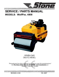
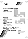
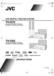
PARTS / SERVICE MANUAL MODELS: CS1, CS2, CSP3 SAW DEVIL® Concrete Saw Models A 100% employee-owned American manufacturer Revision: D 09/2002 P/N 56428 Table of Contents Concrete Saws TABLE OF CONTENTS ................................................................................................... 3-4 USER INFORMATION ..................................................................................................... 5-6 Foreword/Warranty Info ......................................................................................................... 5 LIMITED WARRANTY ........................................................................................................ 6 HEALTH & SAFETY ...................................................................................................... 7-10 Safety Training ....................................................................................................................... 7 Safety Precautions ............................................................................................................ 8-10 TECHNICAL DATA .......................................................................................................11-16 Specifications ........................................................................................................................ 11 Machine Sound and Vibration Measurements ...................................................................... 12 Service Check List ................................................................................................................ 13 Hardware Identification ........................................................................................................ 14 Torque Chart - Imperial ........................................................................................................ 15 Torque Chart - Metric ........................................................................................................... 16 MAINTENANCE ........................................................................................................... 17-22 Important .............................................................................................................................. 17 Electrical Power Supply Connection .................................................................................... 18 CS2 Electrical System .......................................................................................................... 19 CSP3 Electrical System .................................................................................................. 20-21 Troubleshooting .............................................................................................................. 22-23 LUBRICATION ............................................................................................................. 24-25 Lubrication and Service ........................................................................................................ 24 Service Record Chart ............................................................................................................ 25 EXPLODED DIAGRAMS & PARTS LIST .................................................................. 26-63 CS1 Assembly................................................................................................................. 27-33 CS2 Assembly................................................................................................................. 34-43 CSP3 Console Assembly ................................................................................................ 44-49 CSP3 Base Assembly...................................................................................................... 50-55 -3- Table of Contents Concrete Saws EXPLODED DIAGRAMS & PARTS LIST contd ....................................................... 26-63 Blade Guard Assembly ................................................................................................... 56-57 Water Pump Assembly .................................................................................................... 58-59 Water Tank Option Assembly ......................................................................................... 60-61 Decal Identification ......................................................................................................... 62-63 CALIFORNIA PROPOSITION 65 ................................................................................... IBC -4- User Information These instructions include: Safety regulations Operating instructions Maintenance instructions These instructions have been prepared for operation on the construction site and for the maintenance engineer. These instructions are intended to simplify operation of the machine and to avoid malfunctions through improper operation. Foreword/Warranty Info 1. Machine S/N: _______________________________ 2. 3. VIN: ______________________________________ 4. Purchase Date: ______________________________ 5. Dealer/Distributor Information: Name: _____________________________________ Address: ___________________________________ __________________________________________ Always keep these instructions at the place of use of the machine. Observe the safety regulations as well as the guidelines of the civil engineering trade association. Observe safety rules for the operation of equipment and the pertinent regulations for the prevention of accidents. Engine Type: _______________________________ Engine S/N: ________________________________ Observing the maintenance instructions will increase the reliability and service life of the machine when used on the construction site and reduce repair costs and downtimes. Only operate the machine as instructed and follow these instructions. Machine Type: ______________________________ Phone #: ___________________________________ Fax #: _____________________________________ 6. Battery Manufacturer: ______________________________ Battery Type: _______________________________ Battery S/N: ________________________________ Location of above information: Stone Construction Equipment, Inc. is not liable for the function of the machine when used in an improper manner and for other than the intended purpose. Operating errors, improper maintenance and the use of incorrect operating materials are not covered by the warranty. The above information does not extend the warranty and liability conditions of business of Stone Construction Equipment, Inc. 1. Information on S/N tag. 2. Information on engine tag. 3. Information on S/N tag - if applicable. 4. Date you purchased machine. 5. Dealer machine was purchased from. 6. Information on battery and battery warranty card. Stone Construction Equipment, Inc. P.O. Box 150, Honeoye, New York 14471 Phone: (800) 888-9926 Fax: (585) 229-2363 -5- L i m i t e d W a r r a n t y The Manufacturer warrants that products manufactured shall be free from defects in material and workmanship that develop under normal use for a period of 90 days for concrete vibrators and electric pumps, one year for Rhino®, Bulldog®, WolfPac Rollers, trowels, Stompers®, saws, forward plates, engine powered pumps, Lift Jockey, Mortar Buggy and 6 months for all other products from the date of shipment. The foregoing shall be the exclusive remedy of the buyer and the exclusive liability of the Manufacturer. Our warranty excludes normal replaceable wear items, i.e. gaskets, wear plates, seals, Orings, V-belts, drive chains, clutches, etc. Any equipment, part or product which is furnished by the Manufacturer but manufactured by another, bears only the warranty given by such other manufacturer. (The Manufacturer extends the warranty period to “Lifetime” for the drum bearings and seals for the mortar mixers, and agrees to furnish, free of charge, the bearings and seals only upon receipt of the defective parts. The warranty is two years for eccentric bearings on the forward plate compactors, mortar and plaster mixer drums, trowel gearboxes and five years on the Bulldog trench roller eccentric bearings.) A Warranty Evaluation Form must accompany all defective parts. Warranty is voided by product abuse, alterations, and use of equipment in applications for which it was not intended, use of non-manufacturer parts, or failure to follow documented service instructions. The foregoing warranty is exclusive of all other warranties whether written or oral, expressed or implied. No warranty of merchantability or fitness for a particular purpose shall apply. The agents, dealer and employees of Manufacturer are not authorized to make modification to this warranty, or additional warranties binding on Manufacturer. Therefore, additional statements, whether oral or written, do not constitute warranty and should not be relied upon. The Manufacturer’s sole responsibility for any breach of the foregoing provision of this contract, with respect to any product or part not conforming to the Warranty or the description herein contained, is at its option (a) to repair, replace or refund such product or parts upon the prepaid return thereof to location designated specifically by the Manufacturer. Product returns not shipped prepaid or on an economical transportation basis will be refused (b) as an alternative to the foregoing modes of settlement - the Manufacturer’s dealer to repair defective units with reimbursement for expenses, except labor, and be reviewed with the Manufacturer prior to repair. A Warranty Evaluation Form must accompany all warranty claims. Except as set forth hereinabove and without limitation of the above, there are no warranties or other affirmations which extends beyond the description of the products and the fact hereof, or as to operational efficiency, product reliability or maintainability or compatibility with products furnished by others. In no event whether as a result of breach of contract or warranty or alleged negligence, shall the Manufacturer be liable for special or consequential damages including but not limited to: Loss of profits or revenues, loss of use of the product or any associated product, cost of capital, cost of substitute products, facilities or services or claims of customers. No claim will be allowed for products lost or damaged in transit. Such claims should be filed with the carrier within fifteen days. Effective July 2002. Stone Construction Equipment, Inc. • 8662 Main Street, P. O. Box 150 • Honeoye, NY 14471-0150 Phone: 1-800-888-9926 • 1-585-229-5141 Fax: 1-585-229-2363 www.stone-equip.com • e-mail: [email protected] P/N 51018 F-7080 7/2002 Health and Safety Safety Training SAFETY These machines are designed to carry out the function of flat sawing material of the non-cohesive, bituminous and granular varieties. If used correctly they will provide an effective and safe means of flat sawing and meet the appropriate performance standards. It is essential that the operator/driver of the machine is adequately trained in its safe operation, be authorized to operate it, and have sufficient knowledge of the machine to ensure that it is in full working order, before being put to use. -7- Health and Safety Safety Precautions Before using this equipment, study this entire manual to become familiar with its operation. Do not allow untrained or unauthorized personnel, especially children, to operate this equipment. Use only factory authorized parts for service. When warning decals are destroyed or missing, contact the Manufacturer immediately at 1-800888-9926 for replacement. For the safety of yourself and others, it is imperative that the following rules are observed. Failure to do so may result in serious injury or death. This notation appears before warnings in the text. It means that the step which follows must be carried out to avoid the possibility of personal injury or death. These warnings are intended to help the technician avoid any potential hazards encountered in the normal service procedures. We strongly recommend that the reader takes advantage of the information provided to prevent personal injury or injury to others. USE COMMON SENSE WHEN HANDLING FUELS Transport and handle fuel only when contained in approved safety container. Do not smoke when refueling or during any other fuel handling operation. Do not refuel while the engine is running or while it is still hot. If fuel is spilled during refueling, wipe it off from the engine immediately and discard the rag in a safe place. Do not operate the equipment if fuel or oil leaks exist - repair immediately. Never operate this equipment in an explosive atmosphere. Ear protection required when operating this equipment. -8- Health and Safety Safety Precautions Avoid contact with hot exhaust systems and engines. Allow engine to cool before performing any repairs. Never operate unit in a poorly ventilated or enclosed area. Avoid prolonged breathing of exhaust gases. Eye protection required when operating this equipment. Head protection required when operating this equipment. Never operate this equipment without all guards in place. -9- Health and Safety Safety Precautions PRACTICE SAFE MAINTENANCE Understand service procedure before doing work. Keep area clean and dry. Never lubricate, service or adjust machine while it is moving. Keep hands, feet, and clothing from power-driven parts. Disengage all power and operate controls to relieve pressure. Lower equipment to the ground. Stop the engine. Remove the key. Allow machine to cool. Securely support any machine elements that must be raised for service work. Keep all parts in good condition and properly installed. Repair damage immediately. Replace worn or broken parts. Remove any buildup of grease, oil, or debris. Disconnect battery ground cable (-) before making adjustments on electrical systems or welding on machine. DISPOSE OF WASTE PROPERLY Improperly disposing of waste can threaten the environment and ecology. Potentially harmful waste used with equipment includes items such as oil, fuel, coolant, brake fluid, filters, and batteries. Use leakproof containers when draining fluids. Do not use food or beverage containers that may mislead someone into drinking from them. Do not pour waste onto the ground, down a drain, or into any water source. Air conditioning refrigerants escaping into the air can damage the Earths atmosphere. Government regulations may require a certified air conditioning service center to recover and recycle used air conditioning refrigerants. Inquire on the proper way to recycle or dispose of waste from your local environmental or recycling center. SAFETY DECALS - FOR THE SAFETY OF YOURSELF AND OTHERS REPLACE ANY DAMAGED OR MISSING SAFETY DECALS. - 10 - Specifications Concrete/ Pavement Saws Technical Data CS1 Model Dimensions Weight Dimensions lb (kg) (LxWxH) in (cm) 175 lbs CSP3 CS2 (80) 310 lbs (141) 475 lbs (216) 36.5" x 26.6" x 34.5" (92,7 x 67,6 x 87,6) 47.3" x 26.6" x 36.75" (120,1 x 67,6 x 93,3) 54" x 26.75" x 37" (137,2 x 68 x 94) Blade Capacity in (cm) 12", 14" (30,5 / 35,6) 12", 14", 16", 18" (30,5 / 35,6 / 40,6 /45,7) 12," 14", 16", 18", 20" (30,5 / 35,6 / 40,6 / 45,7 / 50,8) Cut Depth in(cm) 3 5/8" w/ 12" blade 4 5/8" w/ 14" blade (9,2) (11,7) 3 5/8" w/ 12" blade 4 5/8" w/ 14" blade 5 5/8" w/ 16" blade 6 5/8" w/ 18" blade (9,2) (11,7) (14,3) (16,8) 3 5/8" w/ 12" blade 4 5/8" w/ 14" blade 5 5/8" w/ 16" blade 6 5/8" w/ 18" blade 7 5/8" w/ 20" blade (9,2) (11,7) (14,3) (16,8) (19,4) Operating System Engines hp/(kW) 9 hp Briggs & Stratton Vang. 11 hp Honda 13 hp Honda *16 hp Briggs & Stratton Vang. 5 hp Electric * electric start (6,7) (8,2) (9,7) (11,9) (3,7) 13 hp Honda *16 hp Briggs & Stratton Vanguard *18 Honda Twin *20 Honda Twin * electric start not recommended for 18" blade (9,7) (11,9) 9 hp Robin (6,7) 8 hp Honda (5,9) 11 hp Honda (8,2) recommended for 12" blade only Dry Element Cyclone Air Cleaner (11 Honda) Air Filter RPM (Hz) 3200 rpm (53) 3200 rpm Fuel Capacity gal (L) 1.6 gal. (6,0) 1.7 gal. 3200 rpm (53) (6,4) (53) 2 gals (7,6) Push Push Hydrostatic Corrosion Resistant, Dual Spray Corrosion Resistant, Dual Spray Corrosion Resistant, Dual Spray Push Push Drive Water System Cyclone Air Cleaner (13 Honda) Remote Cyclone (20 & 18 Honda) Dry Element Cyclone Air Cleaner (11-13 Honda) Engine (13,4) (14,9) Performance Speed ft/ min (m/min) 90 ft/min (27,7 m/min) 3/4" (19,1) Axle (mm) 5/8" (15,9) 3/4" Wheel (R/F) (cm) 8" R / 4" F (20,3 R/10,2 F) 8" R / 4" F Blade Shaft Bearings size in (mm) Greasable pillow block sealed 1" (25,4) Greasable pillow block sealed 1 1/4" (31,8) Greasable pillow block sealed 1 1/4" (31,8) Blade Arbor (size & R/L) 1" R/L (25,4) 1" R/L (25,4) 1" R/L (25,4) Standard Features Options in (mm) Front cutting guide 14" blade guard (19,1) (20,3 R / 10,2 F) 8" R / 4" F (20,3 R / 10,2 F) Lift eye, 4" wheeled front cutting guide, rear Lift eye, 4" wheeled front cutting guide, rear cutting guide, adjustable handles, depth cutting guide, adjustable handles, depth gauge, gauge, Triple V-belt, 14" or 16" blade guard 14",16" or 18" blade guard Pressurized Water pump (except on 13 Honda) 3-5 gal/min. (11-19 l/min) 5 or 8 gal. polyethylene water tanks 5 or 8 gal. polyethylene water tanks † Pointer in up position, Handles in mid-position ‡ Use Imperial measured components only (available from manufacturer) Member Masonry and Concrete Saw Manufacturers Institute and the Concrete Sawing and Drilling Association. - 11 - - Machine Sound and Vibration Measurements Technical Data Sound and Vibration Measurements Sound Pressure Values as measured are per the following: Model/Configuration at operator’s ear CS1 8 HP Honda w/14 in blade 88dBA CS2 11 HP Honda w/14 in blade 93dBA CSP3 18 HP Honda w/20 in blade 91dBA RMS acceleration on the handle were measured per the following: 2 13.16 23.4 18.0 meter/sec Sound and vibration values have been taken in accordance to the EEC machine regulation (edition 93/68/EEC) Sound Pressure measurements were taken with Simpson model 886-2 type 2 meter, calibrated 2/21/97 Acceleration measurements were taken with Quest Tech model VI-100 meter, calibrated 4/17/96 Sound and vibration measurements were obtained with machine operating at maximum engine speed of 3200 RPM. Units had blades mounted and measurements were taken out of cuts. document in cs_rev e_2000.p65 - 12 - Technical Data Service Check List ALL SAWS CSP3 All saws set RPM at 3200 +/- 50 (no load). Run transmission with shifter making sure neutral correlates with neutral at shifter. Check blade clamp hub face run-out with (Adjust at clevis and/or at cable bracket indicator and magnetic chuck. Run-out not on transmission mount). to exceed .015. Set drive axle load springs at 2.38 +/- .06 Check belt tension. inches when axle is in run position. Belt deflection = .19 inches at 4.2 lbs. for used belt and 6.2 lbs for new belt. While engine is running, check wet/dry switch for function. (Dry should run—wet Grease all pillow blocks. should kill engine). Apply never-seize to acme screws. Check water pump switch for function. CS2 Check engage/disengage lever. Drive axle to have .13 minimum clearance to wheel when disengaged. Make sure kill switch is functional while running. For longest service life, use any SAE 20W20 in transmission. CS2 / CSP3 Check depth gauge making sure knob turns when lift crank is run up and down. Check choke and throttle action. - 13 - Technical Data Hardware Identification VR005A ZN = ZINC PLATED BLK = BLACK OXIDE FINISH - 14 - Technical Data Torque Chart - Imperial SAE GRADE 5 Coarse Thread, Zinc-Plated SIZE 1/4 - 20 (.250) 5/16 - 18 (.3125) 3/8 - 16 (.375) 7/16 - 14 (.4375) 1/2 - 13 (.500) 9/16 - 12 (.5625) 5/8 - 11 (.625) 3/4 - 10 (.750) 7/8 - 9 (.875) 1 - 8 (1.000) SAE GRADE 8 Coarse Thread, Zinc-Plated TORQUE ft. lbs. Nm 6 8 13 18 23 31 37 50 57 77 82 111 112 152 200 271 322 436.5 483 655 SIZE 1/4 - 20 (.250) 5/16 - 18 (.3125) 3/8 - 16 (.375) 7/16 - 14 (.4375) 1/2 - 13 (.500) 9/16 - 12 (.5625) 5/8 - 11 (.625) 3/4 - 10 (.750) 7/8 - 9 (.875) 1 - 8 (1.000) SAE GRADE 5 Fine Thread, Zinc-Plated SIZE 1/4 - 28 (.250) 5/16 - 24 (.3125) 3/8 - 24 (.375) 7/16 - 20 (.4375) 1/2 - 20 (.500) 9/16 - 18 (.5625) 5/8 - 18 (.625) 3/4 - 16 (.750) 7/8 - 14 (.875) 1 - 12 (1.000) 1 -14 (1.000) TORQUE ft. lbs. Nm 9 12 18 24 33 45 52 70 80 108 115 156 159 215 282 382 454 615 682 925 SAE GRADE 8 Fine Thread, Zinc-Plated TORQUE ft. lbs. Nm 7 10 14 19 26 35 41 56 64 87 91 123 128 173 223 302 355 481 529 717 541 733 SIZE 1/4 - 28 (.250) 5/16 - 24 (.3125) 3/8 - 24 (.375) 7/16 - 20 (.4375) 1/2 - 20 (.500) 9/16 - 18 (.5625) 5/8 - 18 (.625) 3/4 - 16 (.750) 7/8 - 9 (.875) 1 - 12 (1.000) 1 -14 (1.000) t-chrt_i.doc - 15 - TORQUE ft. lbs. Nm 10 14 20 27 37 50 58 79 90 122 129 175 180 244 315 427 501 679 746 1011 764 1036 Technical Data Torque Chart - Metric Monthly, inspect all hardware on this equipment and engine/motor. Loose hardware can contribute to early component failure and poor performance. Use the torque chart below as a general guideline and keep all hardware tight. Note: Some hardware is used to retain parts that have to move freely for correct operation of this unit. The hardware for these items should be snug enough to prevent excessive play, yet loose enough to allow the parts to pivot freely. Property Class 8.8 ZINC-PLATED SIZE M6 M8 M10 M12 M14 M16 M20 M24 Coarse Thread Nm ft. lbs. 9.9 7 24 18 48 35 83 61 132 97 200 148 390 288 675 498 Fine Thread Nm ft. lbs. 10 7 25 18 49 36 88 65 140 103 210 155 425 313 720 531 Property Class 10.9 ZINC-PLATED SIZE M6 M8 M10 M12 M14 M16 M20 M24 Coarse Thread Nm ft. lbs. 14 10 34 25 67 49 117 86 185 136 285 210 550 406 950 701 Fine Thread Nm ft. lbs. 14 10 35 26 68 50 125 92 192 142 295 218 600 443 1000 738 Property Class 12.9 ZINC-PLATED SIZE M6 M8 M10 M12 M14 M16 M20 M24 Coarse Thread Nm ft. lbs. 16.5 12 40 30 81 60 140 103 220 162 340 251 660 487 1140 841 Fine Thread Nm ft. lbs. 16.5 12 42 31 82 60 150 111 235 173 350 258 720 531 1200 885 Conversion Factor: 1 ft. lb. = 1.3558 Nm - 16 - Maintenance F Concrete Saws IMPORTANT THE PERSON ATTEMPTING ANY OF THE FOLLOWING MAINTENANCE TASKS, MUST BE AUTHORIZED TO DO SO AND HAVE READ AND UNDERSTOOD ALL SECTIONS WITHIN THIS MANUAL - 17 - Electrical Power Supply Connection Maintenance Connecting wires or extension cords should be as short as possible and one piece. In no case should the connecting wires or extension cords be longer than shown in the following chart. RECOMMENDED MAXIMUM LENGTH OF POWER CORD WIRE GAUGE 230V, SINGLE PHASE, 5HP MOTORS #8 110 Feet #6 180 Feet CAUTION: Use of a wire gauge that is too small will cause loss of power and will damage the electric motor. IMPORTANT: Be sure saw is properly grounded prior to operation. Refer to National Electric Code for required grounding methods. cs001a.hpg - 18 - Maintenance CS2 Electrical System - 19 - Maintenance CSP3 Electrical System - 20 - Maintenance CSP3 Electrical System - 21 - Maintenance PROBLEM Troubleshooting CAUSE REMEDY UNEVEN SEGMENT WEAR • (In wet cutting) Insufficient water (usually on one side of blade). • Equipment defects also can cause the segments to wear unevenly. • Flush water system. • Check flow to both sides of blade. • Replace bad bearings, worn arbor shaft or misalignment to spindle. • Check alignment for squareness, both vertically and SEGMENT CRACKS • Blade is too hard for material being cut. • Use a blade with a softer bond/matrix. SEGMENT LOSS • Blade overheats because of lack of coolant (water or air). • Core is worn from undercutting. • Defective collars/flanges set blade out of alignment. • Blade is too hard for material being cut. • Blade is cutting out of round, causing a pounding motion. • Improper blade tension. • (Wet Cutting) Check water lines. Make sure flow is adequate on both sides of blade and there are no blockages. Use sufficient water to flush out the cut. • (Dry Cutting) Run blade free of cut periodically to air cool. • Clean collars/flanges or replace if they are under recommended diameter. • Use proper blade specification for material being cut. • Replace worn bearings; realign blade shaft or replace worn blade mounting arbor. • When ordering blades match shaft speed of saw. • Check spindle speed to ensure blade is running at correct RPM. • Avoid twisting or turning blade in the cut. CRACKS IN CORE • Blade flutters in cut as a result of losing blade tension. • Blade specification is too hard for the material being cut. • Tighten the blade shaft nut. • Make sure blade is running at proper speed and that drive pin is functioning properly. • Use a softer bond/matrix to eliminate stress. LOSS OF TENSION • Core overheating. • Core overheating as a result of blade spinning on arbor. • Core overheating from rubbing the material being cut. • Unequal pressure at blade clamping collars/flanges. • Blade is too hard for the material being cut. • Make certain blade RPM is correct. • Check water flow, distribution and lines. • Tighten the blade shaft nut. • Make certain the drive pin is functioning. • Properly align the saw to square cut. • Collars/flanges must be identical in diameter and the recommended size. • Use a softer bond/matrix to reduce stress. - 22 - Maintenance CAUSE PROBLEM BLADE WOBBLES BLADE WILL NOT CUT UNDERCUTTING THE CORE Troubleshooting • • • • Blade is on a damaged or worn saw. Worn collar. Blade runs at an incorrect speed. Collar /flange diameters are not identical. • Blade is bent as a result of dropping or twisting. • Blade is too hard for material being cut. • Blade has become dull. • Blade does not cut material it was specified for. • Abrasive wearing of the core faster than the segments. REMEDY • Check for bad bearings, bent shaft, or worn mounting arbor. • Check collars/flanges to make sure they are clean, flat and of correct diameter. • Set engine at proper rpm. • Use proper size blade collars/ flanges. • DO NOT USE bent blade. Contact blade manufacturer. • Select proper blade for material being cut. • Sharpen by cutting on softer abrasive material to expose diamonds. If continually sharpening, the blade is too hard for the material being cut. • Break-in on the material to be cut. If it does not dress itself, sharpen as you would a dull • Use water to flush out fines generated during cutting • Use wear-retardant cores. ARBOR HOLE OUT-OFROUND • Collars/flanges are not properly tightened, permitting blade to rotate or vibrate on the shaft. • Collars/flanges are worn or dirty. • Blade is not properly mounted. • Make certain the blade is mounted on the proper shaft diameter. Tighten the shaft nut with a wrench to make certain that the blade is secure. • Clean collars/flanges, make sure they are not worn. • Tighten arbor nut. • Make sure the pin hole slides BLADE WORN OUT OF ROUND • Shaft bearings are worn. • Surges occur because engine is not properly tuned. • Blade arbor hole is damaged from incorrectly mounting the blade. • Bond/matrix is too hard for material. • Blade is slipping, wearing one half of blade more than other. • Install new blade shaft bearings or blade shaft, as required. • Tune engine according to manufacturer's manual. • If core is worn or arbor hole damaged, DO NOT USE. Contact blade manufacturer. • Use proper blade. Consult blade manufacturer. • Replace worn shaft or mounting arbor bushing. • Make certain that drive pin is - 23 - Lubrication Lubrication and Service Lubricants: Check oil levels, wiring, hoses (air, fuel, water) and lubricate machine daily. Engine Oil Repair or replace all worn or damaged components immediately. Check drive belt tension, do not overtension. Make sure machine has full set of matched belts. Check blade shaft, make sure arbor and threads are not worn, damaged, or bent. SAE 10W/30 see engine manual General Grease #1 Lithium Model 6 Transmissions CSP3 Any SAE20W20 Blade shaft bearings should be tight, no free play side-to-side or up and down. Grease blade shaft bearings daily. Blade collars should be clean, free of nicks and burrs. No diameter wear and not out of round. Drive pin not excessively worn or bent and free of gouges. All guards in place and secure. All fasteners tight and secure. Air filter/oil filter (hydraulic or engine) clean. Flush clean water through the pump and spray the assembly every night. This prolongs the pump and blade life. - 24 - Clean machine before starting lubrication maintenance. Insure machine is on solid, level ground before starting maintenance. During lubrication maintenance insure strict cleanliness is observed at all times. To avoid the risk of accidents, use the correct tool for the job and keep tools clean. The draining of engine oil is best carried out when the oil is warm NOT hot. Any spilled oil must be cleaned up immediately. Use only clean containers for oil and only CLEAN, FRESH oils and grease of correct grade. Contaminated Water/Fluids/Oils/Filters Must Be Disposed of Safely. Lubrication Service Record Chart SERVICE RECORD Model No. ____________________________________________ Serial No. ________________________________________________________________ Note: See Engine Manual for Frequency and Part Numbers Date Engine Oil Engine Oil Filter Fuel Filter Notes: - 25 - Air Filter Spark Plugs Transmission Fuel Table of Contents Concrete Saws EXPLODED DIAGRAMS & PARTS LIST .................................................... 26-63 CS1 Assembly ................................................................................................. 27-33 CS2 Assembly ................................................................................................. 34-43 CSP3 Console Assembly ................................................................................. 44-49 CSP3 Base Assembly ...................................................................................... 50-55 Blade Guard Assembly ................................................................................... 56-57 Water Pump Assembly ................................................................................... 58-59 Water Tank Option Assembly ......................................................................... 60-61 Decal Identification ....................................................................................... 62-63 SPECIAL NOTE: All metric hardware to be class 8.8 and all imperial hardware to be grade 2 or better. - 27 - PARTS LIST CS1 Saw Assembly - 28 - PARTS LIST Item CS1 Saw Assembly Part No. Description Qty. 1 47125 Hand Grip 2 2 32295 Flange Bearing 2 3 43374-2 Handle Weldment 1 4 43398-2 Tilt Arm Weldment 1 5 39125 Sheave 3.75 OD 2 6 43393-2 Belt Guard Weldment 1 6a 43288-2 Belt Guard Weldment 11 Honda 1 7 39160 V-Belt 2 8 39299-2 Base Weldment 1 9 39163 Rear Wheel 2 10 39106 Front Wheel 2 11 43454-2 Outside Collar Blade 2 12 43437-2 Inside Collar Blade 2 13 39298-2 Tilt Carriage Weldment 1 14 43365 Blade Shaft 1 15 32296 Pillow Block Bearings 2 16 43389-2 Pointer 1 17 43480-2 Shaft Guard 1 18 43476-2 Engine Deck 1 19 30600 Engine 9 hp Robin 1 19a 30160 Engine 8 hp Honda 1 19b 43285 Engine 11 hp Honda 1 19c 30559 Engine 11 hp Honda Cyclone 1 20* 39169 3/8 Hose to 1/2 NPT 90° Fitting 1 21* 39154 Bulk Head 1/2 NPT Fitting 1 22+ 43279-2 Adjustment Screw Weldment 1 23+ 41036 Tilt Crank Knob 1 24+ 41035 Hand Crank 1 25 39524 Bumper Pointer 1 26 46439 Garden Hose Fitting 1 27* 46144 1/2 NPT Ball Valve 1 28* 39142 1/2 NPT Close Nipple 1 29 39158 Washer 1 inch Internal Star 2 30 39157 Nut 1 inch - 14 2 31 39165 5/16 Spring Pin 2 32 80717 Key 1/4x2-3/4 1 Remarks: ^ Not Shown * Components of Item 36 + Components of Item 39 - 29 - PARTS LIST CS1 Saw Assembly - 30 - PARTS LIST Item Part No. CS1 Saw Assembly Description Qty. 33 80773 3/8x1 Dowel Pin 2 34 55279 Decal CSI Console 1 35^ 43375-2 Wrench 2 36^ 39156 Plumbing Kit 1 37^ 39191 Rubber Bumper 3 38^ 48356 Hose Clamp 2 39^ 23029 Kit Crank Flange Bearing Assembly 1 40^ 23045 Kit Plumbing Gas 1 41^ 32321 Bearing Housing Thrust 1 42 32322 Thrust Bearing 3/4 Bore 1 43 32323 Thrust Washer 3/4 Bore 2 44 36592 Thrust Bearing Spacer 1 45 36605 Shaft Collar 3/4 ID 1 46 80061 Key 1/4 x 1-1/2 (except 11hp Honda) 1 46a 80100 Key 1/4 x 1 (11hp Honda) 1 Remarks: ^ Not Shown * Components of Item 36 + Components of Item 39 - 31 - PARTS LIST CS1 Saw Assembly - 32 - PARTS LIST Item Part No. CS1 Saw Assembly Description Qty. A+ 80775 PINSP 1/4 x 1-1/4 ZN 1 B+ 80557 PINDL 1/4 x 3/4 1 C 80848 BHCS M10-1.5 x 35 4 D 80806 M10 FLAT WASHER (8,11 H) 40 E 80833 M10 NYLOK NUT (8,11H) 18 F 80406 HHCS M8-1.25 x 20 6 G 80812 M8 LOCK WASHER 4 H 80857 M8 FLAT WASHER 6 J 80355 5/8 WASHER 4 K 80768 HHCS 5/8-11 x 6.00 IN 2 L 80804 M10 LOCK WASHER 18 M 80618 HHCS M10-1.5 x 25 3 N 80815 HHCS M10-1.5 x 30 10 P 80051 1/2-13 NYLOK NUT 2 R 80343 1/2 FLAT WASHER 4 S 80082 NUTNY 5/8-11 ZN 2 T 80841 HHCS M10-1.5 x 90 2 U 80838 HHCS M10-1.5 x 50 4 V 80839 HHCS M10-1.5 x 70 4 W 80866 M10-1.5 PLAIN NUT 2 X 80804 M10 LOCK WASHER 4 Remarks: ^ Not Shown * Components of Item 36 + Components of Item 39 - 33 - PARTS LIST CS2 Saw Assembly - 34 - PARTS LIST Item CS2 Saw Assembly Part No. Description Qty. 1 43459-2 Handle Weld CS2 1 2 47125 Grip Handle 2 3* 46439 Garden Hose Fitting 1 4* 46144 1/2 Npt Ball Valve 1 5* 39142 1/2 Npt Close Nipple 1 6* 39154 1/2 Brass Bulkhead 1 7 35321 Battery 1 Year 165 CC (16 B&S) 1 8 43497-2 Battery Strap (16 B&S) 1 9* 39169 90° ½ Npt (M) X 3/8 In Hose Barb 1 10 39180 Knob Depth Gauge 1 11 39164 Bushing Bronze Depth Gauge 1 12 43362 Shaft Depth Gauge CS2/CSP3 1 13 39118 Pulley A6T9-02808 2 14 39117 Pulley A6M9-03110 1 15 36449 Assy Cable Depth Gauge 1 16 48355 Cable Battery 52 In Red (16 B&S) 1 17 48331 Cable Battery 36 In Black (16 B&S) 1 18 39121 Spring Extension Depth 1 19 32321 Bearing Housing Thrust 1 20 43490-2 Arm Tilt Weld CS2 1 21 43383-2 Weldment Console CS2 1 22 43468-2 Belt Guard Weldment CS2 1 23 39125 Sheave 3.75 OD 2B 1 23a 39168 Sheave 3.75 OD 2B (5 Elec) 1 24 39105 Wheel 8 In Diameter 2 25 32294 Flange Bearing 2 26 43461-2 Weldment Tilt Bracket CS2 1 27 39104 Wheel 4 In Diameter 2 28 39157 Nut Half Height 1in-14 2 29 39158 Washer 1 In Internal Star 2 30 80773 Pindl 3/8 X 1 Hard 2 31 43454-2 Outside Collar 2 32 43437-2 Collar Blade Inside 2 33 39124 Sheave 3.75 OD 2B 1 34 32293 Pillow Block Bearing 2 35 39165 Pinsp 5/16 X 1-1/2 Zn 2 Remarks: ^ Not Shown * Components of Item 66 + Components of Item 67 - 35 - PARTS LIST CS2 Saw Assembly - 36 - PARTS LIST Item CS2 Saw Assembly Part No. Description Qty. 36 37717 Key 1/4 X 1/4 X 2-3/16 1 37 43453 Shaft Blade CS2 1 38 39106 Wheel 4 In Diameter (Pointer) 1 39 43494-2 Weld Pointer Front CS2/CSP3 1 40 43489-2 Rod Pointer 2 41 43460-2 Base Weldment CS2 1 42 39159 V-Belt B-33 2 43 43480-2 Guard Shaft All 1 44 43487-2 Weldment Lift Bale CS2 1 45 43329-2 Weldment Motor Deck 9 B&S/5Elec 1 45a 43385-2 Weldment Motor Deck 11,13h/16 B&S 1 46 39136 Engine 9 hp B&S 1 46a 39133 Engine 11 hp Honda Cyclone 1 46b 39131 Engine 13 hp Honda Cyclone 1 46c 39135 Engine 16 hp B&S 1 46d 39137 Engine 5 hp Electric 1 47 39113 Control Throttle 1 48+ 43279-2 Weld Adjust Screw All 1 49+ 41035 Hand Crank 1 50+ 80775 PINSP 1/4 X 1-1/4 ZN 1 51 39524 Bumper Pointer 2 52+ 41036 Knob Tilt Crank 1 53 37136 Kill Switch/Plug 1 53a 47377 Kill Switch/Plug 5 Elec 1 54^ 43326 Wire Harness Kill Switch (9 B&S,11/13H) 1 54a 43327 Wire Harness Kill Switch (16 B&S) 1 55^ 43375-2 Wrench Saw Blade 2 56 43388-2 Spacer Tilt Arm CS2/CSP3 2 57+ 80557 Dowel Pin 1/4 X 3/4 1 58^ 55280 Decal CS2 Console 1 59^ 36398 Cable Plug ( 5 ELEC) 1 60 80893 THBSC M8 x 20 8.8 ZN 2 61^ 48356 Hose Clamp 5/8 OD 2 62^ 39191 Rubber Bumper 3 Remarks: ^ Not Shown * Components of Item 66 + Components of Item 67 - 37 - PARTS LIST CS2 Saw Assembly - 38 - PARTS LIST Item CS2 Saw Assembly Part No. Description Qty. 63^ 39192 Exhaust Deflector (B&S) 1 64 32322 Thrust Bearing 3/4 Bore 1 65 32323 Thrust Washer 3/4 Bore 2 66^ 39156 Plumbing Kit 1 67^ 23029 Kit Crank Flange Bearing Assy 1 68 36605 Shaft Collar 3/4 ID 1 69 37717 Key 1/4 x 1/4 x 2-3/16 (except 11 Honda) 1 69a 80100 Key 1/4 x 11 ( 11 Honda ) 1 Remarks: ^ Not Shown * Components of Item 66 + Components of Item 67 - 39 - PARTS LIST CS2 Saw Assembly - 40 - PARTS LIST Item Part No. CS2 Saw Assembly Description Qty. A 80815 HHCS M10-1.5X30 8.8 ZN 6 B 80804 M10 Lock Washer (Honda, Elec) 22 C 80806 M10 Flat Washer (Honda, Elec) 30 D 80771 SHSHB 1/4 X 5/8 ZN 2 E 80236 NUTKP 1/4-20 ZN 5 F 80833 NUTNY M10-1.5 ZN 19 G 80848 BHSCS M10 X 1.5 X 35 BN 4 H 80406 HHCS M8-1.25 X 20 ZN 7 I 80857 WASHER M8 X 16 FLAT ZN 4 J 80812 WSHRL M8 X 14.8 ZN 4 K 80236 NUTKP 1/4 x 20 ZN 2 L 80618 HHCS M10-1.50 X 25MM ZN 14 M 80767 HHCS 3/4-10 X 7-1/2 ZN 2 N 80344 WASHER 3/4 SAE ZN PL 8 O 80769 NUTNY 3/4-10 ZN 4 P 80844 HHCS M12 X 1.75 X 50 ZN 4 Q 80807 WASHER M12 X 24 FLAT ZN 8 R 80830 NUTNY M12-1.75 ZN 4 S 80196 HHCS 1/2-13 X 3-1/2 ZN 1 T 80343 WASHER 1/2 SAE ZN PL 2 U 80051 NUTNY 1/2-13 21N6813 ZN 1 V 80841 HHCS M10 X 1.5 X 90 ZN 2 W 80866 NUTFX M10-1.5 ZN 2 X 80837 HHCS M10 X 1.5 X 40 ZN 4 Z 80839 HHCS M10 X 1.5 X 70 ZN 1 Z1 80838 HHCS M10 -1.5 X 50 ZN (Honda) 4 Z2 80883 HHCS M8-X 1.25 X 50 ZN (B&S) 4 Z3 80815 HHCS M10 - 1.5 X 30 ZN (Elec) 4 AA 80847 BHSCS M6 X 1 X 20 BN19 2 CC 80851 NUTNY M6 X 1 ZN BN161 2 FF 80812 M8 SPLIT WASHER (B&S) 4 FF1 80804 M10 SPLIT WASHER (Honda,Elec) 4 GG 80857 M8 Flat Washer (B&S) 8 GG1 80806 M10 Flat Washer (Honda,Elec) 8 Remarks: - 41 - PARTS LIST CS2 Saw Assembly - 42 - PARTS LIST Item Part No. CS2 Saw Assembly Description Qty. HH 80817 M8-1.25 Nylok Nut (B&S) 4 HH1 80833 M10-1.5 Nylok Nut (Honda, Elec) 4 JJ 80354 HHCS 1/4-20 X 1.00 IN 2 KK 80571 WSHR FLAT 1/4 4 Remarks: - 43 - PARTS LIST CSP3 Console Assembly - 44 - PARTS LIST Item CSP3 Console Assembly Part No. Description Qty. 1 43426 Pivot tube handle 4 2 35321 Battery 1 year, 165CC (16B&S, 18/20H) 1 3 43497 Strap, battery hold down (16B&S, 18/20H) 1 4 48331 Cable battery 36", black (16B&S, 18/20H) 1 5 48355 Cable battery 52", red (16B&S,18/20H) 1 6 43381-2 Guard-rear cowl 1 7 39118 Pulley A6T9-02808 2 8 36450 Assy cable depth gauge 1 9 39117 Pulley A6M9-03110 1 10 43414-2 Linkage engagement 1 11 38147 Plug 1/8 npt 1 12 46009 Petcock valve & strainer/plug 1 13 39141 Barb hose 1/2 x 3/8 1 14 43499-2 Console weldment 1 15 39126 Switch pressure 1 16 39143 1/2 brass pipe tee 1 17 39144 1/2x1/8 brass reducer 1 18 39180 Knob depth gauge 1 19 35456 Choke Control (16 B&S, 18/20 Honda) 1 19a 47376 Hole Plug (13 Honda) 1 20 39113 Control throttle 1 21 37169 Knob round 2-3/8 blk 2 22 39114 Quadrant control 1 23* 80557 1/4 x 3/4 dowel pin 1 24* 80775 1/4 x 1-1/4 spring pin 1 25* 41035-2 Hand crank 1 26* 41036 Knob tilt crank 1 27 43430 Handle tube 2 28 47125 Grip handle 1" rubber 2 29 43279 Adjustment screw weld 1 30 38562 Switch rocker on/off 1 31 46439 Garden hose fitting 1 32 46144 1/2 ball valve 1 33 39142 1/2 close nipple 2 34 39154 1/2 npt brass bulkhead 1 35 47298 Knob ranger 1 Remarks: ^ Not Shown * Components of Item 46 - 45 - PARTS LIST CSP3 Console Assembly - 46 - PARTS LIST Item CSP3 Console Assembly Part No. Description Qty. 36 42135 Drive lever 1 37 43434-2 Weld engagement linkage 1 38 43362 Shaft depth gauge 1 39 46059 Cap fuel & water 1 40 39116 Switch blank (less water pump) 1 41 39121 Spring extension depth gauge 1 42 39164 Bushing bronze depth gauge 1 43 43318-2 Panel front (13H) 1 43a 43491-2 Panel front 1 44 47377 Hole Plug (13H) 1 44a 31276 Ignition switch (18/20H) - 44b 46363 Key ignition switch - 44c 36399 Fuse 25A ignition - 45 32321 Bearing housing thrust 1 46^ 23029 Kit crank acme assy 1 47^ 55281 Decal console 1 48^ 48356 5/8 OD hose clamps 4 49^ 39191 Rubber bumper 3 50 32322 Thrust bearing 3/4 bore 1 51 32323 Thrust washer 3/4 bore 2 52 36605 Shaft Collar 3/4 ID 1 Remarks: ^ Not Shown * Components of 46 - 47 - PARTS LIST CSP3 Console Assembly - 48 - PARTS LIST Item Part No. CSP3 Console Assembly Description Qty. A 80806 Washer M10 x 20 Flat 10 B 80833 M10-1.4 NYLOK Nut 5 C 80807 Washer M12 x 24 Flat 2 D 80406 HHCS M8-1.25 x 20 15 E 80343 Washer 1/2 Flat 2 G 80857 Washer M8 x 16 Flat 15 H 80843 HHCS M12-1.75 x 30 4 J 80805 Washer M12 x 20 Flat 2 K 80847 BHSCS M6-1 x 12 6 L 80851 M6-1 NYLOK Nut 6 M 80848 BHSCS M10-1.5 x 35 4 N 80770 CRBLT 1/2-13 x 2IN 2 P 80771 SHSHB 1/4 x 5/8IN 2 R 80236 NutKP 1/4-20 3 S 80693 #10-24 NYLOK Nut 2 T 80830 Nut M12-1.75 NYLOK 2 U 80571 Washer M8 x 16 Flat 4 V 80812 Washer M8 x 14.8 Lock 15 W 80354 HHCS 1/4-20 x 1 GR5 2 X^ 80847 BHSCS M6-1 x 12 (18/20H) 2 Y^ 80315 Cotter Pin 3/16 x 2 ZN 1 Remarks: ^ Not Shown - 49 - PARTS LIST CSP3 Base Assembly - 50 - PARTS LIST Item CSP3 Base Assembly Part No. Description Qty. 1 39176 V-Belt A-48 (13HP HONDA) 1 1a 35277 V-Belt A-45 (16 HP B&S, 18/20HP HONDA) 1 2 39115 Cable Control For/Rev 1 3 39166 Clevis 1 4 43322-2 Shifter Bar Weld 1 5 36678 7" Dia. Fan, CW Rotation 1 6 43320-2 Belt Guard Weldment (13HP HONDA) 1 6a 43465-2 Belt Guard Weldment (16HP B&S,18/20HP HONDA) 1 7 39120 Spring, Compression 2 8 39101 Pulley 1 9 32294 Flange Bearing 4 10 39363 Shaft Drive 1 11 39107 Sprocket 40b40, 1" Bore 1 12 43441 Idler Arm 1 13 35203 Vee-Idler Pulley 1 14 38207 Spring, Extension 1 15 39105 Wheel 8" Dia. 2 16 43444-2 Tilt Bracket Weldment 1 17 39104 Wheel 4" Dia. 2 18 39157 Nut 1"-14 Half Height 2 19 39158 Washer 1" Internal Star 2 20 80773 Pin 3/8 X 1" 2 21 43454-2 Collar Outside Universal 2 22 43437-2 Collar Inside 2 23 39123 Sheave 3.75, 3b, 1-1/4 Bore 1 24 32293 Pillow Block Bearing 2 25 39165 5/16 X 1-1/2 Spring Pin 2 26 80717 Square Key .25 X 2.75 1 27 43436 Blade, Shaft 1 28 43494-2 Pointer Bar Weld 1 29 39106 Wheel 4" Dia., Pointer 1 30 43489-2 Pointer Rod 2 31 43406-2 Base Weld 1 32 39112 V-Belt B34 (13HP HONDA) 3 32a 39159 V-Belt B33 (16HP B&S, 18/20HP HONDA) 3 Remarks: ^ Not Shown - 51 - PARTS LIST CSP3 Base Assembly - 52 - PARTS LIST Item Part No. CSP3 Base Assembly Description Qty. 33 43480-2 Shaft Guard 1 34 43385-2 Motor Deck Weld (13 Honda) 1 34a 43447-2 Motor Deck Weld (16 B&S,18/20 Honda) 1 35 43450-2 Lift Bale Weld 1 36 39103 Sheave, Engine (13 Honda,16 B&S) 1 36a 39102 Sheave, Engine (18/20 Honda) 1 36b 39210 Sheave, Engine (20" Guard, Honda) 1 36c 39211 Sheave, Engine (20" Guard, HP B&S) 1 37 39131 Engine, 13hp Honda 1 37a 39134 Engine, 16hp B&S 1 37b 39129 Engine, 18hp Honda 1 37c 37114 Engine, 20hp Honda 1 38 39109 Chain RC40 2.5ft 39 39111 Link, Connecting No.40 1 40 43413-2 Transmission Brkt Weld 1 41 80717 Key Square, Engine 1 42 43388-2 Spacer, Tilt Arm 2 43 43445-2 Tilt Adjust Weldment 1 44 39108 Sprocket, 40b11, .670 Bore 1 45 39100 Pump, Transmission, Model 6 1 46 80100 Key Square 1/4 X 1, Class 1 1 47 80774 Key Woodruff .404 Hard 3 48 39524 Bumper, Pointer 2 49 39193 Exhaust (13 Honda) 1 49a 39138 Exhaust (18 Honda) 1 49b 37115 Exhaust (20 Honda) 1 50^ 39140 Plumbing Kit 1 51^ 38856 Fuel Filter (18/20 Honda) 1 52^ 43315-2 Spacer, Transmission (13 Honda) 4 53^ 39191 Rubber Bumper 3 54^ 43310 Wire Harness (13 Honda) 1 54a^ 43395 Wire Harness (16 Honda) 1 54b^ 43394 Wire Harness (18 Honda) 1 54c^ 37110 Wire Harness (20 Honda) 1 Remarks: ^NOT SHOWN - 53 - PARTS LIST CSP3 Base Assembly - 54 - PARTS LIST Item Part No. CSP3 Base Assembly Description Qty. A 80840 HHCS M10-1.5 x 80 (EXCEPT 13H) 4 A1 80842 HHCS M10-1.5 x 100 (13H) 4 B 80806 WASHER M10 x 20 FLAT 34 B1 80812 WASHER M8 x 14.8 FLAT 4 C 80833 NUT M10-1.5 NYLOK 12 D 80837 HHCS M10-1.5 x 40 4 E 80845 HHCS M16-2 x 160 2 F 80858 WASHER M16 x 30 FLAT 4 G 80852 NUT M16-2 NYLOK 2 H 80618 HHCS M10-1.5 x 25 8 I 80767 HHCS 3/4-10 x 7-1/2IN 2 J 80344 WASHER 3/4 FLAT 8 K 80769 NUT 3/4-10 NYLOK 4 L 80844 HHCS M12-1.75 x 50 12 M 80807 WASHER M12 x 24 24 N 80830 NUT M12-1.75 NYLOK 12 O 80196 HHCS 1/2-13 x 3-1/2IN 1 P 80343 WASHER 1/2 FLAT 2 Q 80051 NUT 1/2-13 NYLOK 1 R 80815 HHCS M10-1.5 x 30 6 S 80406 HHCS M8-1.25 x 20 3 T 80841 HHCS M10-1.5 x 90 2 U 80866 NUTFX M10-1.5 2 V 80804 WASHER M10 x 18., LOCK 18 W 80812 WASHER M8 x 14.8 FLAT 3 X 80838 HHCS M10-1.5 x 50 (13/16/20H) 4 X1 80883 HHCS M8-1.25 x 50 (16B&S) 4 Y 80849 SHSHB M8-1.24 x 20 1 Z 80805 WASHER M12 x 20 FLAT 12 AA 80056 NUT 3/8-16 NYLOK 1 BB 80839 HHCS M10-1.5 x 70 1 CC 80722 HHCS 1/4-20 x 1/2 1 DD 80776 SHCS 1/4-28 x 1/2 4 EE 80571 WASHER 1/4 FLAT 5 FF 80893 THUMB SCREW 2 HH 80843 HHCS M12-1.75 x 30 2 JJ 80124 SHSHB 3/8-16 x 1IN 1 KK 80114 NUT 5/16-18 NYLOK 1 LL^ 80315 COTTER PIN 3/16 x 2 ZN 1 Remarks: ^ Not Shown - 55 - PARTS LIST Blade Guard Assembly - 56 - PARTS LIST Item Part No. Blade Guard Assembly Description Qty. 1* 43358-2 Blade Guard Weld 14 1 1a* 43359-2 Blade Guard Weld 16 1 1b* 43484-2 Blade Guard Weld 18 1 1c* 43309-2 Blade Guard Weld 20 1 2* 43429 Splash Guard 1 3* 39110 Extension Spring 2 4* 39147 Hose Barb 1/8 x 3/8 1 5 39150 3/8 Nylon Braid Hose 4.5 SF 6* 39148 1/8 Branch Tee 1 7* 39149 1/8 90 ° Compression Fitting 2 8* 39170 Water Tubing 14 Guard 2 8a* 39171 Water Tubing 16 Guard 2 8b* 39152 Water Tubing 18/20 Guard 2 9^ 23000 Kit Blade Guard 14 1 9a^ 23001 Kit Blade Guard 16 1 9b^ 23002 Kit Blade Guard 18 1 9c^ 23014 Kit Blade Guard 20 Honda 1 9d^ 23027 Kit Blade Guard 20 B&S 1 10^ 39191 Bumper Rubber 1 A 80812 M8 Flat Washer 2 B* 80406 HHCS M8-1.25 x 20 2 C* 80853 NUTKP M6 x 1 8 D* 80836 HHCS M6-1 x 16 4 E 80806 M10 Flat Washer 2 F 80804 M10 Split Lock Washer 2 G 80842 HHCS M10-1.5 x 100 1 H 80618 HHCS M10-1.5 x 25 1 Remarks: ^ Not Shown * Items included in Blade Guard Kit Item 9 - 57 - PARTS LIST Water Pump Assembly - 58 - PARTS LIST Item Water Pump Assembly Part No. Description Qty. 1 39139 Water Pump 1 2 39173 Hose Barb 1/2 EPDM 1 3 39174 Elbow 1/2 Hose EPDM 1 4 39151 Hose 1/2 Nylo Braid 1.5 FT 5 39145 Hose Barb 1/2 x 1/2 x 1/2 1 6 39126 Pressure Switch 1 7 39144 1/2 x 1/8 Reducer 1 8 39143 1/2 Brass Pipe Tee 1 9 39169 Hose Barb 1/2 x 3/8 90° 1 A 80846 BHSCS M5 x .8 x 30 4 B 80855 Washer M5 4 C 80850 NUTNY M5 x .8 4 Remarks: - 59 - PARTS LIST Water Tank Option Assembly - 60 - PARTS LIST Item Water Tank Option Assembly Part No. Description Qty. 1 43303 Tank Mount Weld CS1 5/8 Gal. 1 1a 43296 Tank Mount Weld CS2 5 Gal. 1 1b 43200 Tank Mount Weld CS2 8 Gal. 1 2 47383 Water Tank 5 Gal. 1 2a 47387 Water Tank 8 Gal. 1 3 47241 Cap 1 4* 39361 Valve 1/4 NPT 1 5* 39215 Quik Connect Nipple 1 6* 39216 Quik Connect Coupler 1 7* 39217 1/8 NPT x 3/8 Hose 1 8 47182 Latch 1 9* 39360 Elbow 90° 1/4 NPT 1 10 39212 Kit Plumbing 1 11^ 23016 Kit Water Tank CS1 5 Gal. 1 11a^ 23017 Kit Water Tank CS2 5 Gal. 1 11b^ 23043 Kit Water Tank CS1 8 Gal. 1 11c^ 23044 Kit Water Tank CS2 8 Gal. 1 A 80618 HHCS M10 - 1.5 x 25 2 B 80804 M10 Lock Washer CS1 5/8 Gal. 2 B1 80804 M10 Lock Washer CS2 5/8 Gal. 4 C 80806 M10 Flat Washer 8 D 80833 M10 Nylok Nut 2 E 80837 HHCS M10 - 1.5 x 40 CS1 2 Remarks: ^ Not Shown * Components of P/N 39212 - 61 - PARTS LIST Decal Identification PN 55289 PN 55287 PN 55291 PN 55292 - 62 - PN 55290 PARTS LIST Item Part No. Decal Identification Description Qty. 1 55156 Decal Notice 1 2 55260 Decal Fuel Off 1 3 55285 Decal Caution Saw Icon 1 4 55286 Decal Before Starting 1 5 55287 Decal Caution Lift Guard 1 6 55288 Decal Danger Carbon Monoxide 1 7 55289 Decal Caution Moving Parts 1 8 55290 Decal Caution No Smoking 1 9 55291 Decal Caution Spark Plug 1 10 55292 Decal Motion F/N/R 1 ^ 23258 Kit Decals Warning CS1 (Includes Items 1, 3-9, 55279, 55282) 1 ^ 23259 Kit Decals Warning Gas CS2 (Incl 1, 5, 7-9, 55269, 55280, 55282) 1 ^ 23274 Kit Decals Warning Elec CS2 (Includes Items 1, 5, 7, 55280, 55282) 1 ^ 23260 Kit Decals Warning CSP3 (Incl 1, 5,7-10, 55269, 55281, 55283) 1 Remarks: ^ Not Shown - 63 - CALIFORNIA PROPOSITION 65 WARNING: Operation of this equipment and/or engine exhaust from this product contains chemicals known to the State of California to cause cancer, birth defects, or other reproductive harm. Bred Tough. Technology Born to Work. The Way It Ought To Be. Stone Construction Equipment, Inc. P.O. Box 150, Honeoye, New York 14471 Phone: (800) 888-9926 Fax: 716-229-2363 e-mail: [email protected] www: stone-equip.com A 100% employee-owned American manufacturer © 1998 Stone Construction Equipment, Inc. Printed in U.S.A. SPR