1
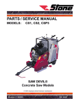
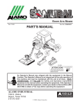
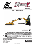
SERVICE / PARTS MANUAL MODELS: WolfPac 4000 ® HONDA GAS DEUTZ DIESEL This equipment has been designed and tested to meet the requirements of the Machinery Safety Directive 89/392/EEC and Amendments and therefore carries the CE Mark REVISION: A 3/99 P/N 56387 TABLE of CONTENTS WolfPac® 4000 FOREWORD ................................................................................................................................... USER INFORMATION .................................................................................................................. LIMITED WARRANTY ................................................................................................................. TECHNICAL DATA ....................................................................................................................... 8 - 10 Specifications .............................................................................................................................. 9 Machine Data .............................................................................................................................. 10 Engine RPM ................................................................................................................................ 10 Machine Sound Level Test .......................................................................................................... 10 HEALTH & SAFETY ..................................................................................................................... 11 - 17 MAINTENANCE ............................................................................................................................. 24 - 33 Maintenance Schedule ................................................................................................................ 26 Engine Oil and Filter ................................................................................................................... 27 Air Cleaner .................................................................................................................................. 27 Fuel Filter .................................................................................................................................... 27 Spark Plugs ................................................................................................................................. 27 - 28 Engine RPM ................................................................................................................................ 28 Cooling System ........................................................................................................................... 28 Valve Clearance .......................................................................................................................... 28 Flywheel Brake ........................................................................................................................... 28 Hydraulic Oil, Filter, and Breather ............................................................................................. 28 - 29 Grease Fittings ............................................................................................................................ 29 Chain ........................................................................................................................................... 29 Fuel Tank/Strainer ....................................................................................................................... 29 Fuel Lines .................................................................................................................................... 29 Forward/Reverse/Neutral ............................................................................................................ 29 Neutral Interlock ......................................................................................................................... 29 Control Cables ............................................................................................................................ 29 Parking Brake .............................................................................................................................. 30 Throttle Lever ............................................................................................................................. 30 Scrapers ....................................................................................................................................... 30 Water Tank/Sprinklers ................................................................................................................. 30 Eccentrics .................................................................................................................................... 30 - 31 TABLE of CONTENTS WolfPac® 4000 Engine Mounting ........................................................................................................................ 31 Hardware, Torque Guidelines, Loctite ........................................................................................ 31 Battery ......................................................................................................................................... 32 Jump Starting .............................................................................................................................. 32 Charge System ............................................................................................................................ 33 Fuse 25A (Honda only) ............................................................................................................ 33 Ignition System ........................................................................................................................ 33 Diesel Belts, Injectors .............................................................................................................. 33 Diesel Electrical Guidelines .................................................................................................... 33 STORAGE ........................................................................................................................................ 33 TROUBLESHOOTING .................................................................................................................. 34 - 37 SERVICE RECORD ....................................................................................................................... 38 - 39 HARDWARE IDENTIFICATION ................................................................................................ 40 EXPLODED DIAGRAMS AND PARTS LIST ............................................................................. 41 - 73 Power Pak Honda Gas ............................................................................................................. 42 - 43 Power Pak Deutz Diesel .......................................................................................................... 44 - 45 Frame Assembly ...................................................................................................................... 46 - 49 Control Levers ......................................................................................................................... 50 - 51 Cable Routing Deutz Diesel .................................................................................................... 52 - 53 Eccentric Assembly ................................................................................................................. 54 - 55 Parking Brake Assembly .......................................................................................................... 56 - 57 Water Tank/Sprinkler Assembly .............................................................................................. 58 - 59 Piping Honda Gas .................................................................................................................... 60 - 61 Piping Deutz Diesel ................................................................................................................. 62 - 63 Hydraulic Schematic Honda Gas ............................................................................................. 64 - 65 Hydraulic Schematic Deutz Diesel .......................................................................................... 66 - 67 Wiring Schematic Honda Gas .................................................................................................. 68 - 69 Wiring Schematic Deutz Diesel ............................................................................................... 70 - 71 Decals ...................................................................................................................................... 72 - 73 CALIFORNIA PROPOSITION 65 WARNING .......................................................................... 74 FOREWORD These instructions include: Safety regulations Operating instructions Maintenance instructions These instructions have been prepared for operation on the construction site and for the maintenance engineer. Please enter (data on machine type plate) These instructions are intended to simplify operation of the machine and to avoid malfunctions through improper operation. Machine Type: ____________________ Observing the maintenance instructions will increase the reliability and service life of the machine when used on the construction site and reduce repair costs and downtimes. Machine No.: ____________________ Engine Type: ____________________ Engine No.: ____________________ Always keep these instructions at the place of use of the machine. Only operate the machine as instructed and follow these instructions. Observe the safety regulations as well as the guidelines of the civil engineering trade association. Observe the safety rules for the operation of road rollers and compactors and the pertinent regulations for the prevention of accidents. Stone Construction Equipment, Inc. is not liable for the function of the machine when used in an improper manner or for other than the intended purpose. Operating errors, improper maintenance and the use of incorrect operating materials are not covered by the warranty. The above information does not extend the warranty and liability conditions of business of Stone Construction Equipment, Inc. Stone Construction Equipment, Inc. P.O. Box 150, Honeoye, New York 14471 Phone: (800) 888-9926 Fax: (716) 229-2363 -5- USER INFORMATION Model/Capacity WolfPac® 4000 Service VIN 1 Purchase Date 2 Engine Make/No. 3 Battery Specification 4 5 6 7 8 9 Oil Specifications & Quantity Engine Hydraulic Distributor -6- Date L i m i t e d W a r r a n t y The Manufacturer warrants that products manufactured shall be free from defects in material and workmanship that develop under normal use for a period of 90 days for concrete vibrators and electric pumps, one year for Rhino®, Bulldog®, Wolfpac Rollers, trowels, Stompers®, saws, forward plates, engine powered pumps, and 6 months for all other products from the date of shipment. The foregoing shall be the exclusive remedy of the buyer and the exclusive liability of the Manufacturer. Our warranty excludes normal replaceable wear items, i.e. gaskets, wear plates, seals, O-rings, V-belts, drive chains, clutches, etc. Any equipment, part or product which is furnished by the Manufacturer but manufactured by another, bears only the warranty given by such other manufacturer. (The Manufacturer extends the warranty period to “Lifetime” for the drum bearings and seals for the mortar mixers, and agrees to furnish, free of charge, the bearings and seals only upon receipt of the defective parts. The warranty is two years for eccentric bearings on the forward plate compactors, mortar and plaster mixer drums, trowel gearboxes and five years on the Bulldog trench roller eccentric bearings.) A Warranty Evaluation Form must accompany all defective parts. Warranty is voided by product abuse, alterations, and use of equipment in applications for which it was not intended, use of non-manufacturer parts, or failure to follow documented service instructions. The foregoing warranty is exclusive of all other warranties whether written or oral, expressed or implied. No warranty of merchantability or fitness for a particular purpose shall apply. The agents, dealer and employees of Manufacturer are not authorized to make modification to this warranty, or additional warranties binding on Manufacturer. Therefore, additional statements, whether oral or written, do not constitute warranty and should not be relied upon. The Manufacturer’s sole responsibility for any breach of the foregoing provision of this contract, with respect to any product or part not conforming to the Warranty or the description herein contained, is at its option (a) to repair, replace or refund such product or parts upon the prepaid return thereof to location designated specifically by the Manufacturer. Product returns not shipped prepaid or on an economical transportation basis will be refused (b) as an alternative to the foregoing modes of settlement - the Manufacturer’s dealer to repair defective units with reimbursement for expenses, except labor, and be reviewed with the Manufacturer prior to repair. A Warranty Evaluation Form must accompany all warranty claims. Except as set forth hereinabove and without limitation of the above, there are no warranties or other affirmations which extends beyond the description of the products and the fact hereof, or as to operational efficiency, product reliability or maintainability or compatibility with products furnished by others. In no event whether as a result of breach of contract or warranty or alleged negligence, shall the Manufacturer be liable for special or consequential damages including but not limited to: Loss of profits or revenues, loss of use of the product or any associated product, cost of capital, cost of substitute products, facilities or services or claims of customers. No claim will be allowed for products lost or damaged in transit. Such claims should be filed with the carrier within fifteen days. Effective April 1, 1998. Bred Tough, Born To Work. The Way It Ought To Be. Phone: 1-800-888-9926 • 1-716-229-5141 Stone Construction Equipment, Inc. Fax: 1-716-229-2363 32 East Main Street, P. O. Box 150 www.stone-equip.com • e-mail: [email protected] Honeoye, NY 14471-0150 -7- 4/98 P/N 51018 Stone WolfPac 4000 – Specifications STONE WolfPac 4000 Honda Gas STONE WolfPac 4000 Deutz Diesel Operating Wt. 4425 lbs. (2007 kg) 4520 lbs. (2050 kg) Dry Wt. 3784 lbs. (1716 kg) 3879 lbs. (1759 kg) Ballasted Wt. 6045 lbs. (2742 kg) 6140 lbs. (2785 kg) 106" x 47" x 68" (2692 x 1194 x 1727 mm) 106" x 47" x 68" (2692 x 1194 x 1727 mm) Drum Width 40" (1016 mm) 40" (1016 mm) Drum Diameter 30" (762 mm) 30" (762 mm) Wall Clearance 2.0" (51 mm) 2.0" ( 51 mm) Curb Clearance 14" (356 mm) 14" (356 mm) 68” (1727 mm) 68” (1727 mm) Engine - hp (kW) 20 hp Honda Gas (14,9 kW) 20 hp Deutz Diesel (14,9 kW) Engine RPM Control: Hand Throttle 1400 RPM Idle 3100 RPM Full 1400 RPM Idle 2600 RPM Full 8 Gallons (30 Liters) 8 Gallons (30 Liters) Hydrostatic / Rear Drum Drive Hydrostatic / Rear Drum Drive Hydrostatic (Power Steering) Hydrostatic (Power Steering) Center Point Articulated Center Point Articulated MODEL Dimensions Lx Wx H Wheel Base Operating System Fuel Capacity Drive Steering Frame o + 30 Articulation + 30o o + 15 + 15o Gravity Feed Gravity Feed Water Tank Capacity 65 Gallons (246 Liters) 65 Gallons (246 Liters) Scrapers (2 per drum) Urethane Urethane Front Drum / External Front Drum / External Centrifugal Force 3500 lbs. (15,5 kN) 3500 lbs. (15,5 kN) Static Linear Force Front / Rear F:60.5 lbs/In. (10,6 N/mm) R: 90.5 lbs/In. (15.9 N/mm) F:60.5 lbs/In. (10,6 N/mm) R: 90.5 lbs/In. (15.9 N/mm) Dynamic Linear Force Front / Rear 148 lbs/In. (25,9 N/mm) 148 lbs/In. (25,9 N/mm) Static Linear Force Average 75 lbs/In. (13.3 N/mm) 75 lbs/In. (13.3 N/mm) 3400 vpm (56,7 Hz) 3400 vpm (56,7 Hz) 30% 30% Oscillation Water Control Performance Vibrating Drum Frequency Gradeability Outside Turning Radius 6.0 ft / 10.0 ft (1.83 m / 3.05 m) 2 2 6.0 ft / 10.0 ft (1.83 m / 3.05 m) Max. Area Cap. ft /hr 79,200 ft /hr (7358m /hr) 79,200 ft2 /hr (7358m2/hr) Travel Speed 0 - 4.5 m.p.h. (7.25 kM/hr) 0 - 4.5 m.p.h. (7.25 kM/hr) Spring Loaded Urethane (4) Scrapers Hour Meter, Low Oil Shut Down Safety Neutral Switch Parking Brake - Hand Operated Hydraulic Bypass Extra Hydr, Filter Padded Arm Rests Spring Loaded Urethane (4) Scrapers Hour Meter, Low Oil Pressure Light Safety Neutral Switch Parking Brake - Hand Operated Hydraulic Bypass Extra Hydr, Filter Padded Arm Rests 2 Standards -8- Machine Data/Engine RPM/ Machine Sound Level Test TECHNICAL DATA Machine Data B r a ke s Ser vice Pa r k i n g hy d r o s t a t i c ma n u a l o p e ra t i o n f r i c t i o n Recommended Fuel Gas Unit Diesel Unit ga s o l i n e 8 6 o c t a n e m i n i mu m diesel fuel blend c a p a c i t y 8 ga l l o n s 1 2 vo l t s y s t e m b a t t e r y B C I g r o u p 7 0 5 5 0 c c a 2 0 a m p c h a rg e s y s t e m Electr ic Hydraulic Oil AT F D e x r o n I I I / M e r c o n t y p e c a p a c i t y 1 2 ga l l o n s / 4 5 . 4 l i t e r s Eng ine Oil Gas Unit Diesel Unit SAE 10W30 API SH OR SJ / ca pacity 1.5 quar t (1.32 l) SAE 15W/40 API CC OR CD/ca pacity 3 quar ts (2.75 l) N G K B R P 6 E S ga p . 0 2 8 - . 0 3 1 i n . ( . 7 - . 8 m m ) Spark Plugs Engine RPM Do not exceed eccentric rpm, adjust engine rpm to obtain proper eccentric speed. A minimum idle RPM is required to run the cooler fan. Full RPM should not be exceeded and will void the engine warranty. IDLE RPM Honda Gas Deutz Diesel 1400 MIN 1400 MIN FULL RPM Honda Gas Deutz Diesel 3100 +100 2600 +100 ECCENTRIC FULL SPEED RPM 3400 +50 Machine Sound Level Test Machine Type: Sound Level Meter Calibration Date: Meter Type: Test Date: WolfPac 4000 - Gas September 30, 1996 Simpson Model 886-2 Type 2 September 30, 1996 Test Conditions: Temperature: Ambient Sound: Soil Condition: Moisture Limit: Engine Speed: Frequency: Test Site: Sound Level at Operator Position: 65 degrees Fahrenheit/18 degrees Celsius 60 dba slow mode Rubber Pad 3100 RPM/50 Hz 3400 VPM/ 56,7 Hz Honeoye, New York USA 94 dba without vibe 97 dba with vibe -9- HEALTH & SAFETY Before using this equipment, study this entire manual to become familiar with its operation. Do not allow untrained or unauthorized personnel, especially children, to operate this equipment. Use only factory authorized parts for service. Safety Precautions When warning decals are destroyed or missing, contact the Manufacturer immediately at 1-800-888-9926 for replacement. For the safety of yourself and others, it is imperative that the following rules are observed. Failure to do so may result in serious injury or death. FOLLOW SAFETY INSTRUCTIONS Carefully read all safety messages and decals in this manual and on your machine safety signs. Keep decals in good condition. Replace missing or damaged decals. Be sure new equipment components and repair parts include the current safety signs. Replacement safety signs and decals are available through your dealer. Learn how to operate the machine and how to use controls properly. Do not let anyone operate without instruction. Keep your machine in proper working condition. Unauthorized modifications to the machine may impair the function and/or safety and affect machine life. If you do not understand any part of this manual and need assistance, contact your dealer. This notation appears before warnings in the text. It means that the step which follows must be carried out to avoid the possibility of personal injury or death. These warnings are intended to help the technician avoid any potential hazards encountered in the normal service procedures. We strongly recommend that the reader takes advantage of the information provided to prevent personal injury or injury to others. UNDERSTAND SIGNAL WORDS A signal word DANGER, WARNING, or CAUTION is used with the safety-alert symbol. DANGER identifies the most serious hazards. DANGER or WARNING safety signs are located near specific hazards. General precautions are listed on CAUTION safety signs. CAUTION also calls attention to safety messages in this manual. - 10 - HEALTH & SAFETY Safety Precautions USE COMMON SENSE WHEN HANDLING FUELS Transport and handle fuel only when contained in approved safety container. Do not smoke when refueling or during any other fuel handling operation. Do not refuel while the engine is running or while it is still hot. If fuel is spilled during refueling, wipe it off from the engine immediately and discard the rag in a safe place. Do not operate the equipment if fuel or oil leaks exist - repair immediately. Never operate this equipment in an explosive atmosphere. Operator must always be seated when roller is running. Never allow more than one person on roller. Always turn engine off before dismounting from roller. Always apply parking brake when not in use. Never park roller on a hill. Never operate roller on slope greater than 15 degrees. Do not operate the roller in standing water. Ear protection required when operating this equipment. Exposure to loud noise can cause impairment or loss of hearing. HOT SURFACES Muffler, engine, and engine shroud may be hot. Allow all components in the engine compartment to cool before performing any service work. Never operate unit in a poorly ventilated or enclosed area. Avoid prolonged breathing of exhaust gases. Engine exhaust fumes can cause sickness or death. - 11 - HEALTH & SAFETY Safety Precautions Qualified personnel only. No untrained operators. Serious injury may occur. Users must be trained to operate this roller. Read the Operator's Manual and Engine Owner's Manual. Learn to operate this roller safely. Do not articulate on grades larger than 15o, roller may tip over. Do not operate across the sides of hills, roller may tip over. Do not operate at the edge of mats or roads, roller may tip over. Do not stand, be seated when roller is running. Do not park the roller on hills. Always turn off engine and apply brake before dismounting. Hydraulic system produces high pressures--incorrect hose replacement can cause serious personal injury. When performing service, refer to Operator's Manual for hose identification and connections. Caution: Escaping hydraulic fluid under pressure can have sufficient force to penetrate the skin, causing serious personal injury. Hydraulic fluid escaping under pressure from a very small hole can be almost invisible. Use a piece of cardboard or wood to search for possible leaks. Never use your hands to detect pressure leaks. Hydraulic tank temperature can reach 180o F maximum. Pressurized release of fluids from hydraulic system can cause serious burns. Shut off engine. Only remove filler cap when cool enough to touch with bare hands. Slowly loosen cap to first stop to relieve pressure before removing completely. Never perform any work on the roller while it is running. Before working on the roller, stop the engine and disconnect the spark plug wire(s) to prevent accidental starting, block drums to prevent rolling. Keep engine cover closed during the operation. Keep hands, clothing and jewelry away from all moving parts. Keep all guards in place. - 12 - HEALTH & SAFETY Safety Precautions Keep feet clear of all drums. Keep work area free of bystanders. For foot protection, wear steel toe shoes or toe pads. Caution: Keep away from the machines articulation area when the engine is running. Only start engine from operators seat. Before starting machine, make sure that there are no persons or obstacles near or under machine. PRACTICE SAFE MAINTENANCE Understand service procedure before doing work. Keep area clean and dry. Never lubricate, service or adjust machine while it is moving. Keep hands, feet, and clothing from power-driven parts. Disengage all power and operate controls to relieve pressure. Lower equipment to the ground. Stop the engine. Remove the key. Allow machine to cool. Securely support any machine elements that must be raised for service work. Keep all parts in good condition and properly installed. Fix damage immediately. Replace worn or broken parts. Remove any buildup of grease, oil, or debris. Disconnect battery ground cable (-) before making adjustments on electrical systems or welding on machine. PREPARE FOR EMERGENCIES Be prepared if a fire starts. Keep a first aid kit and fire extinguisher handy. Keep emergency numbers for doctors, ambulance service, hospital, and fire department near your telephone. - 13 - HEALTH & SAFETY Safety Precautions Starting fluid (ether) is highly flammable, do not use or an explosion or fire may result. WEAR PROTECTIVE CLOTHING Wear close fitting clothing and safety equipment appropriate to the job. Prolonged exposure to loud noise can cause impairment or loss of hearing. Wear a suitable hearing protective device such as earmuffs or earplugs to protect against objectionable or uncomfortable loud noises. Operating equipment safely requires the full attention of the operator. Do not wear radio or music headphones while operating machine. PREVENT BYPASS STARTING Avoid possible injury or death from engine runaway. Do not start engine by shorting across starter terminal. Engine will start with PTO engaged if normal circuitry is bypassed. Start engine only from operators station with PTO disengaged or in neutral. DISPOSE OF WASTE PROPERLY Improperly disposing of waste can threaten the environment and ecology. Potentially harmful waste used with equipment include such items as oil, fuel, coolant, brake fluid, filters, and batteries. Use leakproof containers when draining fluids. Do not use food or beverage containers that may mislead someone into drinking from them. Do not pour waste onto the ground, down a drain, or into any water source. Air conditioning refrigerants escaping into the air can damage the Earths atmosphere. Government regulations may require a certified air conditioning service center to recover and recycle used air conditioning refrigerants. Inquire on the proper way to recycle or dispose of waste from your local environmental or recycling center. - 14 - MAINTENANCE F WolfPac® 4000 IMPORTANT The person attempting any of the following maintenance tasks must be authorized to do so and have read and understood all sections within this manual. - 15 - MAINTENANCE CHART - 16 - WolfPac® 4000 MAINTENANCE WolfPac® 4000 MAINTENANCE NOTE: Please dispose of used motor oil and filter in a manner that does not harm the environment. WARNING BEFORE MAKING ANY ADJUSTMENTS, BE SURE THE ROLLER IS PARKED ON LEVEL GROUND, PARKING BRAKE IS ON AND DRUMS ARE BLOCKED. DISCONNECT BATTERY TO AVOID ACCIDENTAL IGNITION OF ENGINE. SEVERE PERSONAL INJURY MAY OCCUR. Under heavy loads, change engine oil and filter more frequently. AIR CLEANER HONDA IMPORTANT: Read Honda Emission Warranty Statement and Engine Manual before operating or performing maintenance. Paper Element: Tap the element lightly on a hard surface to remove excess dirt or blow pressurized air (30 psi max.) through the filter from the air cleaner cover side. Do not brush the dirt off. ADDITIONAL SERVICE INFORMATION This is not a detailed engine service manual. If you want more detailed service information refer to engine manuals: 56237 Manual Engine Gx620 56238 Manual Shop Gx620 ENGINE OIL AND FILTER HONDA DEUTZ Remove the air cleaner cup, empty the oil, and clean. Fill with oil to the level mark, install. FUEL FILTER Replace oil at 50 hours, then change oil every 100 hours. Change the oil filter every 200 hours. 1. Remove the oil filler cap, drain bolt (and oil filter when required). Drain oil into a suitable container. 2. Clean and install the drain bolt, tighten securely. When required, install new oil filter and lightly oil filter seal. HONDA Remove the Honda control cover and inspect filter, replace if water or dirt sediment is found. Replace Honda and in-line filter at scheduled maintenance. DEUTZ Replace at scheduled maintenance, lightly oil filter seal. SPARK PLUG 3. Fill with the recommended oil, fill to the upper limit mark on the dipstick, and tighten the oil filler cap securely. 4. Run engine for 2 3 minutes, stop engine, check oil level, and check for leaks. Replace elements if damaged or excessively dirty. DEUTZ Replace oil at 20 hours, then change oil every 100 hours. Change the oil filter every 200 hours. Foam Pre-Cleaner: Clean in warm soapy water, rinse, and dry thoroughly. Apply oil to the foam and squeeze out excess oil. The engine will smoke if too much oil is left in the foam. Recommended spark plug: BPR6ES (NGK) W20EPR-U (NIPPONDENSO) To ensure proper engine operation, the spark plug must be properly gapped and free of deposits. Clean and replace at scheduled maintenance. Clean engine before removing spark plugs. Visually inspect - 17 - MAINTENANCE WolfPac® 4000 the spark plug, discard if insulator or tip is damaged. Check that the spark plug washer is in good condition. If spark plug is to be reused, clean with a wire brush and set plug gap .028 - .031in (.70 - .80mm). Thread the spark plug in by hand to prevent cross threading. After the spark plug is seated, tighten with a spark plug wrench to compress the washer. If installing a new spark plug, tighten 1/2 turn after the spark plug seats to compress the washer. If reinstalling a used spark plug, tighten 1/8 1/4 turn after the spark plug seats to compress the washer. NOTICE The spark plug must be securely tightened. An improperly tightened spark plug can become very hot and may cause engine damage. Use only the recommended spark plug or equivalent. A spark plug that has an improper heat range may cause engine damage. ENGINE RPM Start the engine and allow it to warm up to normal operating temperature, check the idle speed (1,400 + 100), and adjust idle stop screw as required. VALVE CLEARANCE/FLYWHEEL BRAKE Due to special tool requirements and training, an authorized engine dealer should perform this service unless the owner has the proper tools and proper shop manuals. HYDRAULIC OIL WARNING ESCAPING HYDRAULIC FLUID UNDER PRESSURE CAN HAVE SUFFICIENT FORCE TO PENETRATE THE SKIN, CAUSING SERIOUS PERSONAL INJURY. HYDRAULIC FLUID ESCAPING UNDER PRESSURE FROM A VERY SMALL HOLE CAN BE ALMOST INVISIBLE. USE A PIECE OF CARDBOARD OR WOOD TO SEARCH FOR POSSIBLE LEAKS. NEVER USE YOUR HANDS TO DETECT PRESSURE LEAKS. IF YOU ARE INJURED BY ESCAPING HYDRAULIC FLUIDS, SEE A DOCTOR AT ONCE. SERIOUS INFECTION OR REACTION CAN DEVELOP IF PROPER MEDICAL TREATMENT IS NOT ADMINISTERED IMMEDIATELY. Exxon ATF Dexron III or Mercon hydraulic oil is recommended for the hydraulic system. Do not mix hydraulic oils. Check oil level daily, replace hydraulic oil every 800 hours. 1. Clean hydraulic tank, remove oil breather cap slowly. Check the full speed, Honda 3,100 + 100, Deutz 2,600 + 100, and adjust full speed stop screw as required. Notice the idle and full speed RPM setting should not be modified or eccentric system may be damaged. See Eccentric for proper operating speed. 2. Remove drain plug and drain into suitable container. COOLING SYSTEM 3. Clean drain plug, apply thread sealant to the plug, install and tighten. The machine should be cleaned at scheduled maintenance. This should include cleaning the air inlet screens, the oil cooler and the engine cooling fins. Wash machine with warm soapy water, rinse off mud and dirt with water, and use pressurized air (30-psi max.) to blow dirt and debris from oil cooler fins and engine. (Diesel is equipped with removable air deflector). - 18 - 4. Add fresh hydraulic oil until level is visible in the sight gauge. A 1/4 1/2 air bubble will be seen at the top of the gauge. 5. Clean breather cap, install and tighten. 6. Idle engine 2-3 minutes, stop engine and check oil level. MAINTENANCE WolfPac® 4000 CAUTION: If hoses, filter and/or hydraulic components were changed, start the engine and purge the air from the system prior to checking the oil level. To do this, idle the engine for three minutes with control lever in neutral position. Slowly engage forward to reverse. This allows fluid to replace air introduced with the filter change. If this procedure is not followed, partial or complete failure of the pump may result. CHAIN HYDRAULIC OIL FILTER CHAIN ADJUSTMENT Replace at five hours. This is to rid the system of any trapped contamination from the wear-in of parts. Then replace every 100 hours. Use beta rated filter (i.e. Parker 12AT-10C,10 micron filter). Remove back panel, loosen mounting bolts on side and adjust with adjusting bolt to tighten chain 3/8 to 1/2 inch chain slack. For further chain adjustment, remove the half link. Retighten mounting bolts and replace panel. Avoid overtightening chain as this causes excessive wear and power loss. Lubricate weekly with chain lube, inspect connecting links and check chain slack 3/8-1/2 inch. Chain lubrication is required weekly. To avoid sprocket wear, replace chain when fully stretched. For chain replacement, use only factory authorized parts. 1. Remove the spin-on hydraulic oil filter. 2. Lightly oil the seal on the new filter, install and tighten. FUEL TANK/STRAINER Drain and flush the fuel tank every 150 hours or yearly. Remove the strainer petcock and clean. 3. Idle engine 2-3 minutes, stop engine, check for proper hydraulic oil level, and check for leaks. FUEL LINES CAUTION: Never overfill the hydraulic tank. Use the sight gauge located on the hydraulic tank. A 1/4-1/2 air bubble will be seen at the top of the gauge showing the fluid level. Inspect fuel line condition and clamps weekly. Replace fuel lines every two years. Before disconnecting any hydraulic lines, be sure engine is shut off and relieve all pressure. Before applying pressure to system, be sure all connections are tight and lines, fittings and hoses are not damaged. The forward/reverse lever should be aligned with NEUTRAL on the console when the roller is moving neither forward nor backward with the engine running. If the lever is not aligned, adjust it as described below. 1. Shut off the engine with the forward/reverse lever left in operating neutral position, the position when the roller moves neither forward nor reverse. Apply the parking brake. HYDRAULIC BREATHER CAP Replace every 800 hours or yearly. FORWARD/REVERSE/NEUTRAL ADJUSTMENT GREASE FITTINGS Use a grease gun to grease below fittings, use lithium grease. Remove the blue protection cap off fitting before greasing. Hinge (8) fittings Left rear bearing (1) fitting Front RH/LH bearing (1) fitting per side 2. Open the engine hood of the machine. 3. Disconnect the linkage from the hydrostatic transmission from the clevis. Do this by removing the lock nut from the clevis pin and removing the pin. 4. Now screw clevis in or out to adjust. - 19 - MAINTENANCE WolfPac® 4000 5. Secure the clevis to the transmission lever with the clevis pin, secure with the lock nut and tighten clevis nut. Linkage play must be minimal at both connections. Replace clevis and/or link if required. OR DEATH COULD RESULT. CONTROL CABLES WHICH HAVE MOISTURE INSIDE OF THEM AND/OR HAVE FROZEN SHOULD BE REPLACED. DO NOT APPLY HEAT TO THAW OR DRY CONTROL CABLES. PARKING BRAKE NEUTRAL INTERLOCK It should take a force of 25-35 pounds, applied at the end of the brake lever, to apply the brake lever. The brake should prevent the roller from moving when applied. Turn knob on brake lever to adjust. Clockwise will increase the force, counterclockwise will decrease it. In the event this lever force cannot be obtained, adjust the brake shoes via the star wheel. The star wheel may be accessible through a slot located in the brake cover plate on the rear right side of the machine. The purpose of the neutral interlock switch is to prevent the engine starting when the forward/reverse lever is not in the neutral position. 1. Disconnect battery cables from battery. 2. a. Disconnect (2) wires from neutral interlock switch and connect it to leads from an ohmmeter. b. When switch is actuated, ohmmeter should read zero resistance. NOTE:Before adjusting star wheel, back off the brake lever knob (counterclockwise) to gain adjustment at knob. 3. Adjustments must be made at transmission. 4. Disconnect ohmmeter and reconnect interlock wires and battery cables. THROTTLE LEVER CONTROL CABLES Throttle should operate smoothly and hold engine at full RPM. Throttle should require 10 lbs. to operate. To adjust tension, loctite locknut and tighten until 10 lbs. is required to move from full to idle position. Refer to illustration below for assembly information travel 1 1/8. Forward/reverse, brake, throttle, and choke. Lubricate all cable ends every 200 hours with penetrating oil. WARNING DO NOT ADJUST THE CONTROL CABLE WITH THE POWER ON OR THE ENGINE RUNNING. SERIOUS INJURY OR DEATH COULD RESULT. A GRADUAL OR SUDDEN INCREASE IN THE NO-LOAD FRICTION (CABLE DISCONNECT AT BOTH ENDS) OF A CONTROL CABLE IS AN INDICATION OF A PENDING OR PRESENT PERFORMANCE PROBLEM. THE CONTROL CABLE SHOULD BE REPLACED, OTHERWISE SERIOUS INJURY OR DEATH COULD RESULT. A GRADUAL OR SUDDEN DECREASE IN THE USABLE STROKE IS AN INDICATION OF A PENDING OR PRESENT PERFORMANCE PROBLEM. THE CONTROL CABLE SHOULD BE REPLACED, OTHERWISE SERIOUS INJURY SCRAPER MAINTENANCE/ADJUSTMENT Scrapers must make uniform contact across entire width of drum to ensure even application of water from the sprinkler system. There are three aspects of scraper adjustment for uniform contact. First, spring tension is - 20 - MAINTENANCE WolfPac® 4000 adjusted by sliding hinge mechanism (refer to item 18 on Mainframe Assembly) in or away from drum surface. ECCENTRICS For optimum urethane contact, 10 lbs. of spring tension is recommended. Second, the urethane portion of the scrapers can be extended or retracted. Finally, the scrapers may be shifted side to side for centering on the drum. Refer to Mainframe Assembly and follow these steps: When vibratory compaction is necessary, engage eccentrics by pushing hydraulic valve lever all the way forward. Operator may vary the frequency and therefore the centrifugal force by varying engine RPM. Eccentrics should be turned off whenever the roller is stopped, or stopped to change direction. Do not run the eccentric on any non-yielding surface, such as concrete or aged asphalt. NOTE:Test vibration with front drum on soft ground. Run engine at full RPM to obtain vib speed 3400 + 50 check per below. 1. Loosen 7 bolts, holding items 16 & 59, on the assembly until the nuts are flush with ends of bolts. To check vibration with a vibrotach, place the vibrotach on the vibrating member surface, record reading when the wire reaches maximum movement. (Vibrotach P/N 37891). Adjust engine RPM to obtain proper eccentric speed. 2. Loosen the 4 bolts that hold item 15 to the hinges. 3. Loosen the 2 bolts that hold item 18 to the frame and slide away or towards the drum. When checking vibration with a strobe light, place a horizontal line on the vibrating member surface. Check with strobe light-record reading when the line reaches minimum movement. NOTE:The spring tension should now be minimal and adjustments of the urethane exposure, side to side position on the drum, and relative distance to the unit (spring tension) from the drum can all be set for optimum performance. ENGINE MOUNTING 4. To assemble, reverse the above procedure making sure that proper adjustment of each sequence is achieved before retightening the bolts. Check weekly. Tighten all mounting hardware for proper torque, refer to parts illustrations for proper torque. HARDWARE WATER TANK The water tank is polyethylene to prevent corrosion. The water tank holds 65 US gallons. Dirty water will clog the sprinkler bars. If the water tank is subject to freezing temperatures, all the water lines and the water tank must be drained by drawing through sprinkler tubes or removing the cover at the rear of the machine to gain access to the water tank, flush and drain plug. Inspect all hardware for tightness. Refer to parts illustrations for proper torque. SPRINKLERS The sprinkler tube assemblies are PVC to prevent corrosion. The sprinkler tube assemblies are equipped with a clean out plug for cleaning when required. - 21 - MAINTENANCE WolfPac® 4000 TORQUE GUIDELINES DO NOT use these values if a different torque value or tightening procedure is given for a specific application. Torque values listed are for general use only. Check tightness of fasteners periodically. SAE GRADE 5 C o a rs e T h re a d S IZ E 1 /4 – 2 0 ( . 2 5 0 ) 5 /1 6 – 1 8 ( .3 1 2 5 ) 3 /8 – 1 6 ( . 3 7 5 ) 7 /1 6 – 1 4 ( .4 3 7 5 ) 1 /2 – 1 3 ( . 5 0 0 ) 9 /1 6 – 1 2 ( .5 6 2 5 ) 5 /8 – 1 1 ( . 6 2 5 ) 3 /4 – 1 0 ( . 7 5 0 ) 7 /8 – 9 ( .8 7 5 ) 1 – 8 ( 1 .0 0 0 ) PLATED 6 ft. lb s . 1 3 ft. lb s . 2 3 ft. lb s . 3 7 ft. lb s . 5 7 ft. lb s . 8 2 ft. lb s . 1 1 2 f t. lb s . 2 0 0 f t. lb s . 3 2 2 f t. lb s . 4 8 3 f t. lb s . 8 Nm 18 N m 31 N m 50 N m 77 N m 111 N m 152 N m 271 N m 4 3 6 .5 N m 655 N m PLATED 9 ft. lb s . 1 8 ft. lb s . 3 3 ft. lb s . 5 2 ft. lb s . 8 0 ft. lb s . 1 1 5 f t. lb s . 1 5 9 f t. lb s . 2 8 2 f t. lb s . 4 5 4 f t. lb s . 6 8 2 f t. lb s . 12 N m 24 N m 45 N m 70 N m 108 N m 156 N m 215 N m 382 N m 615 N m 925 N m SAE GRADE 8 C o a rs e T h re a d S IZ E 1 /4 – 2 0 ( . 2 5 0 ) 5 /1 6 – 1 8 ( .3 1 2 5 ) 3 /8 – 1 6 ( . 3 7 5 ) 7 /1 6 – 1 4 ( .4 3 7 5 ) 1 /2 – 1 3 ( . 5 0 0 ) 9 /1 6 – 1 2 ( .5 6 2 5 ) 5 /8 – 1 1 ( . 6 2 5 ) 3 /4 – 1 0 ( . 7 5 0 ) 7 /8 – 9 ( .8 7 5 ) 1 – 8 ( 1 .0 0 0 ) Make sure fasteners threads are clean and that you properly start thread engagement. This will prevent them from failing when tightening. LOCTITE Loctite 262 threadlocker is required to prevent hardware from loosening. Refer to exploded diagrams and parts list for * indicating where loctite is required. SERVICING BATTERY PLATED 7 ft. lbs. 14 ft. lbs. 26 ft. lbs. 41 ft. lbs. 64 ft. lbs. 91 ft. lbs. 128 ft. lbs. 223 ft. lbs. 355 ft. lbs. 529 ft. lbs. 541 ft. lbs. 10Nm 19 Nm 35 Nm 56 Nm 87 Nm 123 Nm 173 Nm 302 Nm 481 Nm 717 Nm 733 Nm PLATED 10 ft. lbs. 20 ft. lbs. 37 ft. lbs. 58 ft. lbs. 90 ft. lbs. 129 ft. lbs. 180 ft. lbs. 315 ft. lbs. 501 ft. lbs. 746 ft. lbs. 764 ft. lbs. 14Nm 27 Nm 50 Nm 79 Nm 122 Nm 175 Nm 244 Nm 427 Nm 679 Nm 1011 Nm 1036 Nm SAE GRADE 8 Fine Thread SIZE 1/4 – 28 (.250) 5/16 – 24 (.3125) 3/8 – 24 (.375) 7/16 – 20 (.4375) 1/2 – 20 (.500) 9/16 – 18 (.5625) 5/8 – 18 (.625) 3/4 – 16 (.750) 7/8 – 9 (.875) 1 – 12 (1.000) 1 – 14 (1.000) Fasteners should be replaced with the same or higher grade. If higher grade fasteners are used, these should only be tightened to the strength of the original. BATTERY SAE GRADE 5 Fine Thread SIZE 1/4 – 28 (.250) 5/16 – 24 (.3125) 3/8 – 24 (.375) 7/16 – 20 (.4375) 1/2 – 20 (.500) 9/16 – 18 (.5625) 5/8 – 18 (.625) 3/4 – 16 (.750) 7/8 – 14 (.875) 1 – 12 (1.000) 1 – 14 (1.000) Shear bolts are designed to fail under predetermined loads. Always replace shear bolts with identical grade. WARNING BATTERY GAS CAN EXPLODE. KEEP SPARKS AND FLAMES AWAY FROM BATTERIES. USE A FLASHLIGHT TO CHECK BATTERY ELECTROLYTE LEVEL. NEVER CHECK BATTERY CHARGE BY PLACING A METAL OBJECT ACROSS THE POSTS. USE A VOLTMETER OR HYDROMETER. ALWAYS REMOVE GROUNDED NEGATIVE (-) BATTERY CLAMP FIRST AND REPLACE IT LAST. 1. On regular batteries, check electrolyte level. Fill each cell to bottom of filler neck with distilled water. - 22 - MAINTENANCE WolfPac® 4000 2. Keep batteries clean by wiping them with a damp cloth. Keep all connections clean and tight. Remove any corrosion and wash terminals with a solution of 1 part baking soda and 4 parts water. Tighten all connections securely. If you spill acid on yourself: 1. Flush your skin with water. 2. Apply baking soda or lime to help neutralize the acid. NOTE: Coat battery terminals and connectors with a mixture of petroleum jelly and baking soda to retard corrosion. 3. Flush your eyes with water for 10 15 minutes. Get medical attention immediately. 3. Keep battery fully charged, especially during cold weather. If a battery charger is used, turn charger off before connecting charger to battery(ies). Attach POSITIVE (+) battery post. Then attach NEGATIVE (-) battery charger lead to a good ground. Once a month, check the battery for proper charge of 12.5 volts. Check for proper fluid level. Use distilled water when adding and run 30 minutes to mix. Clean battery, posts, and terminals. Disconnect battery cables before charging to avoid damage to the electrical system. WARNING SULFURIC ACID IN BATTERY ELECTROLYTE IS POISONOUS. IT IS STRONG ENOUGH TO BURN SKIN, EAT HOLES IN CLOTHING, AND CAUSE BLINDNESS IF SPLASHED INTO EYES. If acid is swallowed: 1. Drink large amounts of water or milk. 2. Then drink milk of magnesia, beaten eggs, or vegetable oil. 3. Get medical attention immediately. In freezing weather, run engine at least 30 minutes to assure thorough mixing after adding water to battery. If necessary to replace battery(ies), replacements must meet or exceed the following recommended capabilities at - 18° C (0° F): 12 Volt Standard duty battery BCI group 70 550CCA BATTERY INSTALLATION WARNING Avoid the hazard by: ALWAYS CONNECT GROUNDED CABLE LAST. CLEAN AND SECURELY CONNECT EACH CABLE TO BATTERY TERMINAL OF THE SAME POLARITY. BATTERY SHOULD BE SECURELY FASTENED WITH PROPERLY INSTALLED HOLD-DOWNS. 1. Filling batteries in a well-ventilated area. 2. Wearing eye protection and rubber gloves. 3. Avoiding breathing fumes when electrolyte is added. JUMP STARTING 4. Avoiding spilling or dripping electrolyte. 5. Use proper jump start procedure. CAUTION: Do not let vehicles touch. Put emergency brake ON. Set both vehicles in PARK (NEUTRAL if manual transmission) and turn ignition and electrical accessories off. - 23 - MAINTENANCE WolfPac® 4000 Attach jumper cables in this order: DIESEL ONLY 1. dead positive block to BELT TENSION 2. good positive Check belts weekly for proper tension. Belt deflection at 1/8 inch at 7 pounds is recommended. A slight amount of belt deflection should be noticed. The 3V belt design can handle a larger amount of HP. For optimum performance, replace belt yearly. If any belt squealing is present, belts must be tightened or replaced. 3. good negative to 4. engine block or frame of dead car. Start GOOD vehicle and let run a few minutes. Then start DEAD VEHICLE. Remove cables in reverse order 4, 3, 2, 1. FUEL INJECTORS CHARGE SYSTEM Charge system should be checked every month. With the engine running at full speed voltage should be 13 14 volts. SWITCH BOX/FUSE 25A (HONDA ONLY) If charge system fails, check the fuse located at the key switch box. If fuse fails frequently it usually indicates a short circuit or an overload in the electrical system. Refer to wiring diagram and inspect wires. NOTICE: Electrical system is not designed for field add-on electrical options, do not modify the electrical system. Contact your authorized dealer. Service or replace fuel injectors every 500 hours. WARNING DO NOT ATTEMPT TO DISASSEMBLE OR ADJUST THE FUEL INJECTORS YOURSELF. REMOVE THEM FROM THE ENGINE AND HAVE THEM SERVICED BY AN AUTHORIZED ENGINE DEALER. DIESEL ENGINE ELECTRICAL SYSTEM INSTALLATION GUIDELINES When installing new or reworking used diesel engines, this list of guidelines should be strictly adhered to. Following these guidelines should prevent damage to the electrical system of diesel engines. SPECIFIED FUSE: 25A Turn the engine switch OFF and remove the key before checking or replacing fuses to prevent accidental shortcircuiting. To replace fuse pull the old fuse out of the clips with your finger. Push a new fuse into the clips. Always disconnect the positive cable from the battery before performing any work on the machine that involves welding or working on the electrical system. NOTICE: Never use a fuse with a different rating from that specified. Serious damage to the electrical system or a fire may result. Avoid jump starting a diesel engine. Either change the battery or remove the positive cable and charge the battery. Do not alter or change the wiring harness. Cold weather add ons should not be needed. IGNITION SYSTEM The 20 hp Honda is equipped with electronic ignition. Checking and replacing the spark plug is the only ignition system maintenance required. - 24 - MAINTENANCE WolfPac® 4000 When cleaning machine, caution should be used around regulator area. Direct spraying of the regulator is not good. (Regulator should be covered or protected if direct spraying will happen). Excessive water pressure may also loosen wire connections or start terminals corroding. After cleaning, all terminals should be dried if wet and connections checked for proper seating. STORAGE 1. Store the roller on level ground with drums blocked and parking brake on. 2. Remove the key. Operations of roller by untrained persons could result in personal injury. 3. In freezing climates, drain the water from the water tank, sprinkler tubes and drums. 4. During extended storage, drums should be coated with any type of oil or grease to prevent rusting. 5. Storage instructions for the engine are stated in the Engine Manual and should be carried out. - 25 - TROUBLESHOOTING PROBLEM Engine Won't Start Engine won't start but cranks over. WolfPac® 4000 CAUSE REMEDY Forward/Reverse lever not in neutral position. Place lever in neutral position. Battery not fully charged. Charge or replace. Loose battery or starter cables. Check and tighten. Faulty engine starting circuit. Check appropriate section in Engine Manual Faulty or improperly adjusted neutral interlock switch. Make sure neutral switch is adjusted properly and wires are all secured. Test with ohmmeter. Readjust neutral switch. Replace if defective. Dirty fuel injectors. (Diesel Only) Clean or replace. Petcock plugged. Clean or replace. Low on fuel. Add fuel. Fuel valve closed. Open. Fuel filter plugged. Check fuel filter, replace if necessary. Spark plug wire (2) disconnected. (Gas Only) Connect. Spark plug fouled. (Gas Only) Clean or replace. No spark at plug. (Gas Only) Check engine ignition system in Engine Manual. Service or replace. Clean or replace. Disengage. - 26 - TROUBLESHOOTING PROBLEM CAUSE WolfPac® 4000 REMEDY Water/dirt in fuel. Drain fuel system. Choke remains on. (Gas Only) Adjust choke cable. Clean choke linkage. Carburetor improperly adjusted. (Gas Only) Adjust as per Engine Manual. Dirty fuel injectors. (Diesel Only) Service or replace. Injection pump drawing in air. (Diesel Only) Check fuel lines or replace. Objects in front of drums. Remove. Unit in bypass. Check bypass valve. Loose or broken forward/reverse linkage. Readjust linkage or replace worn arm linkage. Loose or broken chain. Make sure chain is on sprocket. Adjust tension or replace if chain shows excessive war. Loose or broken transmission belts. Replace and/or tighten. Low hydraulic oil. Check oil level gauge. Add if required. Unit lacks power moving forward--but okay in reverse or vice versa. Improperly adjusted forward/ reverse linkage. Adjust linkage so that lever travel is the same in either direction from neutral. Unit lacks power. Engine not properly warmed up. Idle before operating to achieve operating temperature. Low hydraulic oil level. Add. Plugged hydraulic filter. Replace. Insufficient belt tension. Check and adjust belts. Engine RPM too low. Check throttle linkage for proper actuation (3100 RPM Gas/2600 Diesel). See Maintenance. Engine starts but does not keep running. Roller won't move forward or reverse. - 27 - TROUBLESHOOTING PROBLEM Unit lacks power. WolfPac® 4000 CAUSE REMEDY Dirty fuel filter. Replace. Dirty fuel injectors. Service or replace. Injection pump drawing in air. Check fuel lines or replace. Too much oil in crankcase. Drain and check. Service or replace. Air filter dirty. Clean and/or replace. Faulty hydraulic pump or drive motor. Test hydraulic pressure, gas 3000 PSI/diesel 2250 PSI, at full load on drive motor with engine at full RPM. Replace pump if pressure is not in specified range in hydraulic motor drive circuit. Replace drive motor if measured pressure is correct. Oil Consumption Blue Smoke Overheated Bearings seized up. Check drums for resistance. Too much oil in crankcase. Drain Loose oil filter or sending unit. Tighten Loose bolts. Tighten Worn valves. Replace Worn cylinder & piston rings. Replace Too much oil in crankcase. Drain--fill to proper level Crankcase oil level low. Fill to proper level Restricted exhaust. Clean or replace Cooling Fins dirty. Clean Defective injector (Diesel Only). Replace - 28 - TROUBLESHOOTING PROBLEM Unit won't steer Brakes don't hold properly Asphalt sticks to roller WolfPac® 4000 CAUSE REMEDY Cylinder--leaking. Replace hydraulic cylinder Piston rod bent. Replace hydraulic cylinder Missing hydraulic cylinder pin. Replace Kinked or broken hoses. Replace Low hydraulic fluid. Add fluid Faulty hydraulic pump. Check hydraulic steering circuit for maximum pressure of 800 psi at full rpm. Replace or repair by authorized Service Center. Brakes not adjusted. Adjust by turning knob at end of brake lever, handle or additional adjustment required at star wheel. Loose or broken brake cable. Make sure cable is secure. Replace if necessary. Brake shoes worn out. Replace. Insufficient water supply on drums. Fill tank and adjust flow. Check and clean sprinkler tubes. Check and clean water tank. Check hoses for kinks or dirt. Urethane scrapers not making contact allowing water to leak past. Adjust or replace if necessary. Sand/replace. - 29 - SERVICE RECORD WolfPac® 4000 Ser vice Record Model No. Roller S/N: Engine S/N: Record Hours and Dates of Maintenance Below. Engine Oil and Filter Change Air Cleaner Ser vice Fuel Filter Spark Plugs Engine RPM Cooling System Valve Clearance Flywheel Brake Hydraulic Oil, Filter and Breather Grease Fittings Chain Fuel Tank/Strainer Fuel Lines Control Cables Water Tank/Sprinklers Eccentrics Engine Mounting Hardware Batter y Charge System Diesel Belts, Injectors - 30 - HARDWARE IDENTIFICATION - 31 - WolfPac® 4000 PARTS LIST Exploded Views with Parts Power Pak Honda Gas ....................................................................................................................... 42 - 43 Power Pak Deutz Diesel .................................................................................................................... 44 - 45 Frame Assembly ................................................................................................................................ 46 - 49 Control Levers ................................................................................................................................... 50 - 51 Cable Routing Deutz Diesel .............................................................................................................. 52 - 53 Eccentric Assembly ........................................................................................................................... 54 - 55 Parking Brake Assembly ................................................................................................................... 56 - 57 Water Tank/Sprinkler Assembly ........................................................................................................ 58 - 59 Piping Honda Gas .............................................................................................................................. 60 - 61 Piping Deutz Diesel ........................................................................................................................... 62 - 63 Hydraulic Schematic Honda Gas ....................................................................................................... 64 - 65 Hydraulic Schematic Deutz Diesel .................................................................................................... 66 - 67 Wiring Schematic Honda Gas ........................................................................................................... 68 - 69 Wiring Schematic Deutz Diesel ........................................................................................................ 70 - 71 Decals ................................................................................................................................................ 70 - 71 - 33 - PARTS LIST Power Pak - Honda Gas - 34 - PARTS LIST Power Pak - Honda Gas ITEM PART NO. DESCRIPTION QTY. 1 43775 Engine 20HP Honda GX620 1 56237 Manual Owners GX620 1 56238 Manual Shop GX620 1 2 39093 Adaptor 1 3 39586 Pump Var. Disp. 1 4 39587 Pump Gear 1 5 47301 O-Ring 3-1/4ID x 1/16CS 1 6 43224-2 Mount Honda 1 7 43542-2 Lever Forward/Reverse Gas 1 8 43229-2 Support Pump 1 9 30562 Manifold Muffler Kit 1 # 39552 Cover Fuel Filter 1 10 43234-2 Tube Weld Exhaust 1 11 39094 Coupling Engine 1 12 39095 Coupling Pump 1 13 39096 Insert 1 14 46186 Fuel Line 4 ft. 15 46186 Fuel Line 1 ft. 16 34089 Clamp 4 17 38856 Filter 1 TORQUE ITEM PART NO. DESCRIPTION QTY. FT. LBS. Nm A* 80179 HHCS 3/8-16 x 2 GR5 ZN 4 23 (31) B 80342 WSHR 3/8 SAE ZN 10 - - C 80056 NUTNY 3/8-16 ZN 5 - - D* 80476 HHCS 3/8-16 x 1-1/2 GR5 ZN 9 23 (31) E 80058 WSHRL 3/8 Split ZN 8 - - F 80936 HWHST M4 x 10mm 4 - - G 80890 HHCS M5 x 30 8.8 ZN 2 - - H 80775 PINSP ¼ x 1-1/4 ZN 1 - - J* 80145 HHCS 3/8 - 16 x 1-1/4 GR5 ZN 4 23 31 # Not Shown * Loctite Required - 35 - PARTS LIST Power Pak - Deutz Diesel C - 36 - PARTS LIST Power Pak - Deutz Diesel TORQUE ITEM PART NO. DESCRIPTION QTY. FT. LBS. Nm 1 38467 SHV 3V 2 GR 4.12 x3/4 1 7.5 5.5 2 29353 SPCR FAN MTG 1 - - 3 35936 FAN HYD 7 IN 10 BLDCCW 1 - - 4 38470 BELT 3V x 280 2 - - 5 38075 SHV 3V 3GR 4 12 x 1-7/16 1 7.5 5.5 6 39573 SHV 13V47 x 3/4 1 7.5 5.5 8 30253 ENGINE DIESEL 1 - - 9 28543-2 CLAMP BATTERY 1 - - 10 29758-2 BRKT WELD NEUT SW 1 - - 11 38543 BATTERY 1 - - 12 38483 FILTER OIL DIESEL 1 - - 17 38499 BELT 3V x 250 1 - - 20 47244 RBR 60 DURO 1.5 x 6.75 5 - - 22 43007-2 BRKT WELD ECC PUMP 1 - - 23 38501 FILTER FUEL 1 - - 24 46186 HOSE LOW PRESS 1/4 ID 31 - - 26 34089 CLAMP HOSE 4 - - 28 47203 SHOCK MTG 4 - - 29 38644 MUFFLER NELSON 1 - - 30 38646 CLAMP MUFFLER 1-1/4 1 - - 31 38645 MANIFOLD NELSON 1 - - 32 38647 GASKET MANIFOLD 2 - - 33 29604-2 PLT SPRT PUMP BRKT 1 - - 34 29459-2 BRKT MTG DECK 2 - - 35 46186 HOSE FUEL LINE .25 OD 18 - - 36 29461-2 DECK WELD 1 - - 38 29609 SHOCK MTG MODIFY 2 - - 39 29462-2 BRACKET MTG FILTER 1 - - - 37 - PARTS LIST Power Pak - Deutz Diesel Contd. C - 38 - PARTS LIST Power Pak - Deutz Diesel Contd. TORQUE ITEM PART NO. DESCRIPTION QTY. FT. LBS. Nm A 80116 WSHRL 1/4 MED SPLIT 3 - - B 80347 WSHR 1/4 WROT 3 - - C 39355 SET BOLT BATTERY 1 - - D 80342 WSHR FLAT 3/8 SAE 16 - - E 80056 NUTNY 3/8 - 16 21 23 31 F 39221 KEY EATON PUMP 1 - - G* 80145 HHCS 3/8 - 16 x 1-1/4 GR5 ZN 4 23 31 H 80121 KEY 3/8 x 3/8 x 1-1/2 (incl.w/#5) 1 - - I* 80181 HHCS 3/8 - 16 x 2-1/2 GR5 ZN 4 23 31 J 80444 KEY #9 WOODRUFF 1 - - K 80540 HHTB 3/8 - 16 x 3 GR5 2 23 31 L 80042 NUTFX 3/8 - 16 2 23 31 M 80058 WSHRL 3/8 MED SPLIT 19 - - P* 80174 HHCS 3/8 - 16 x 1 GR8 ZN 2 23 31 T* 80374 HHCS 3/8 - 16 x 3/4 1 23 31 U 80630 THDRD 5/16 - 18 x 10 1/2 2 - - V 80114 NUTNY 5/16 - 18 2 13 18 W 80348 WSHR 5/16 WROT USS 2 - - X* 80154 HHCS 1/4 - 20 x 1-1/4 3 6 8 Y 80246 NUTKP 5/16 - 18 2 13 18 Z* 80451 HHTB 5/16 - 18 x 1-1/4 2 - - CC* 80378 HHCS 1/2 - 13 x 1ZN 2 57 77 DD 80117 WSHR 1/2 MED SPLIT 2 - - EE* 80610 HWHST 3/8 - 16 x 1-1/2 4 23 31 FF* 80615 HHTB 3/8 - 16 x 1-1/2 4 23 31 GG* 80539 SHCS 3/8 - 16 x 2-1/2 8 23 31 HH* 80470 HHCS 3/8 - 16 x 1 GR5 ZN 8 23 31 *Loctite Required - 39 - PARTS LIST Frame Assembly KK LL X, L - 40 - PARTS LIST Frame Assembly ITEM PART NO. DESCRIPTION QTY. 1 37009 Shock Mtg 4 2 43221-2 Tank Weld Fuel - Gas/Diesel 1 38147 Plug 1/8 NPT Hex HD 1 3 46009 Pet Cock 1 4 46186 Hose Low Press 1/4 ID - Gas 3 6 47246 Grommet RBR 1 ID x 1.25 GD 1 7 46365 Ftg Hyd EL 1/8 NPT x 1/4 H - Diesel 1 8 38210 Cap Fuel 1 9 47257 Grommet RBR .69 ID x 1.00 GD 1 10 43226-2 Frame Weld Main Gas/Diesel 1 11 46655 Column Steering 1 12 43118-2 Plate Steering 1 13 37191 Spr Pkg Gibson 1164-2 Red 2 14 29360-2 Plt Cover Door Mtr 1 15 29388-2 Plt Scraper 4 16 29010 Scraper Slotted Urethane 4 17 29395-2 Pivot Scraper 8 18 29389-2 Rod Weld Scraper 8 19 29611-2 Pnl Weld Side Access 1 20 42685-2 Sprkt Weld 72th 1 21 38153 Chain Set No. 80 1 34536 Link Half no. 80 1 34537 Link Connection No. 80 1 23 38151 Sprkt H8012 x 1.00 1 24 22849 Drum Weld Rear 1 25 29379 Spcr Drm Fnt LH 1 26 32232 Brg Ball Flg 1-1/2 ID 1 27 29025-2 Plt Brg Mtg LH Rear 1 28 22771 Kit Scraper Assy 4 29 29162-2 Adj Weld Drm Mtr 1 30 47203 Shock Mount 4 31 47195 Seat Assy 1 32 38143 Arm Rest (Set RH & LH) 1 33 41017 Wheel Steering 1 34 46656 Nut Wheel Steering 1 35 47401 Cap Wheel Steering 1 36 29745-2 Plate Access Air - Diesel 1 37 35456 Cable Choke - Gas 1 41002 Cable Stop - Diesel 1 - 41 - PARTS LIST Frame Assembly Contd. - 42 - PARTS LIST Frame Assembly Contd. ITEM PART NO. DESCRIPTION QTY. 38 34086 Clamp Hose - Diesel 1 39 43235-2 Panel Str Cover - Honda 1 43236-2 Panel Str Cover - Diesel 1 40 36268 Hour Meter 1 41 29158-2 Pnl Flr Comfort Angle 1 42 43834-2 Pnl Flr Inside 1 43836 Window Emission 1 80908 PPHNS 10 - 24 x 3/4 ZN 4 80693 NUTNY D-24 ZN 4 80346 WSHR #10 SAE ZN 4 43 29001-2 Pnl Weld Top Access 1 44 38111 Latch Lvr Adj 1 45 22472-2 Pin Weld Pivot ART/OSC 2 46 22437-2 Hng Weld ART/OSC 1 47 22438-2 Frm Weld Frt 1 48 47247 Grommet Rubber 2 ID 2 49 29008-2 Cover Eccentric Housing 1 50 22475-2 Frame Weld Eccentric Housing 1 51 22531-2 Drum Weld Front 1 52 28986 Spacer Drum RH Front 1 53 22470-2 Mounting Weld Drum Motor 1 54 29228-2 Panel Weld Floor Access Battery 1 55 29298 Skid Tread Mod 1 56 32236 Bearing Ball Flg 2 ID 2 57 46042 Fitting 1641B 8 58 47001 Cap Plug Blue 8 59 29387-2 Backer Scraper 4 TORQUE ITEM PART NO. DESCRIPTION QTY. FT. LBS. Nm A 80051 NUTNY 1/2 - 12 14 57 77 B 80117 WSHRL 1/2 MED SPLIT 9 - - C* 80089 HHCS 1/2 - 13 x 1-3/4 GR5 ZN 4 57 77 D 46172 PLUG PIPE 1 NPT SKT HD 4 - - * Loctite Required - 43 - PARTS LIST Frame Assembly Contd. - 44 - PARTS LIST Frame Assembly Contd. TORQUE ITEM PART NO. DESCRIPTION QTY. FT. LBS. Nm E* 80569 SHCS 1/2 - 13 x 1-1/2 BLK 2 57 77 F 80551 HHTB 1/2 - 13 x 3 GR5 ZN 1 - - G* 80085 HWHTB 5/16 - 18 x 1 THDFR 13 13 18 H* 80578 HHCS 1/2 - 14 x 3 GR5 ZN 4 57 77 I* 80290 FHSCS 3/8 - 16 x 1-1/4 BLK 17 23 31 J 80348 WSHR 5/16 WROT ZN 4 - - K 80114 NUTNY 5/16 - 18 ZN 8 13 18 L* 80811 HHCS M6 x 25mm 8.8 ZN 4 18 24 M 80169 HHCS 5/16 - 18 x 2 GR5 ZN 2 18 24 N* 80561 HHCS 1/2 - 13 x 1-3/4 GR5 ZN 5 57 77 O 80056 NUTNY 3/8 - 16 ZN 51 23 31 P 80027 NUTFL 1-1/4 ZN 2 57 77 Q 80058 WSHRL 3/8 MED SPLIT 22 - - R* 80470 HHCS 3/8 - 16 x 1 GR5 ZN 8 23 31 S* 80539 SHCS 3/8 - 16 x 2-1/2 BLK 8 23 31 T 80031 HWHTB 1/2 - 13 x 1-1/2 THDFRM 4 57 77 U 29132 PIN HNG 3/16 x 19-1/2 1 - - V 29362 PIN HNG 3/16 x 18-1/4 1 - - W 80125 WSHR 17/32 x 1-1/16 6 - - X 80860 WSHRL M6 SPLIT ZN 4 - - Y* 80577 HHCS 5/8 - 11 x 2 GR5 ZN 6 112 152 Z 80082 NUTNY 5/8 - 11 ZN 8 97 71 AA 80338 WSHR 1 IN WROT ZN 2 - - BB* 80585 SHCS 5/8 - 11 x 2 BLK 2 112 152 CC 80563 NUTJM 1/2 - 13ZN 1/2 HGTH 1 49 - DD 80586 HWHTB 5/16 - 18 x 1/2 4 13 18 EE 80347 WSHR 1/4 WROT ZN 4 - - FF* 80587 CRBLT 3/8 - 16 x 1 28 - - GG 80043 WSHR 3/8 SAE 52 - - HH 80424 PINCT 1/8 x 3/4 8 - - II* 80163 HHCS 5/16 - 18 x 1-1/2 4 13 18 JJ* 80088 HHCS 3/8 - 16 x 1-1/4 GR8 8 23 31 KK* 80161 HHCS 5/16 - 18 x 1 GR5 ZN 4 13 18 LL 80086 WSHRL 5/16 SPLIT ZN 4 - - * Loctite Required - 45 - PARTS LIST Control Levers - 46 - PARTS LIST Control Levers ITEM PART NO. DESCRIPTION QTY. 1 39197 Throttle Assembly 1 39202 Cable Assembly Throttle 1 35456 Cable Choke Gas 1 41002 Cable Stop Diesel 1 3 38095 Brake Assembly 1 4 41003 Cable Assembly Brake 1 5 39097 Control Forward/Reverse 1 39321 Switch Neutral/Backup 1 6 38602 Cable Forward/Reverse 1 7 41007 Clamp Cable 1 8 43542-2 Lever Forward/Reverse Gas 1 43218-2 Lever Forward/Reverse Diesel 1 80051 NUTNY 1/2-13 ZN Diesel 1 80015 Key Woodruff Diesel 1 9 38561 Clevis 1 10 43219-2 Bracket Forward/Reverse Cable 1 2 TORQUE ITEM PART NO. DESCRIPTION QTY. FT. LBS. Nm A* 80851 NUTNY M6 1 7 (10) B 39203 WSHR Slotted 1 - - C 39204 WSHR Nylon 1 - - D 80461 HWHST 10-32 x ½ 6 3 (4) E* 80163 HHCS 5/16-18 x 1-1/2 GR5 ZN 4 13 (18) F 80086 WSHRL 5/16 Split ZN 2 - - G* 80686 HHCS 3/8-16 x 3/4 GR8 ZN 2 23 (31) H 80058 WSHRL 3/8 Split ZN 2 - - I 80043 WSHR 3/8 WROT ZN 2 - - J 80788 WSHR SPR 1/4 ID 1/2 OD SST 4 - - K 80771 SHSHB 1/4 x 5/8 ZN 2 - - L 80693 NUTNY 10-24 ZN 2 - - * Loctite Required - 47 - PARTS LIST Cable Routing - Deutz Diesel 3 - 48 - PARTS LIST Cable Routing - Deutz Diesel ITEM PART NO. DESCRIPTION QTY. 1 41007 Clamp Conduit 1 2 29761 Clup Spring 1 3 41006 Collar Stop 1 4 29610 Bracket Guide Cable 1 5 47271 Heat Shrink 1 TORQUE ITEM PART NO. DESCRIPTION QTY. FT. LBS. Nm A* 80461 HWHTB 10 - 32 x 1/2 THRDFRM 2 3 4 B* 80609 RHSMS 8 - 32 x 5/16 BLK 1 - - C* 80616 HHCS M10 x 16mm ZN 1 35 48 D 80058 WSHRL 3/8 MED SPLIT ZN 1 - - E* 80617 HHCS M6 x 16mm ZN 1 7 10 * Loctite Required - 49 - PARTS LIST Eccentric Assembly - 50 - PARTS LIST Eccentric Assembly ITEM PART NO. DESCRIPTION QTY. 1 39587 Motor AVR w/HI-PSI Seal 1 2 43003-2 Mtg Weld DM4 1 3* 39075 CPLG Jaw L-090 x .625 1 4 38081 Insert Sox L090 1 5* 38080 CPLG Jaw L-090 x .750 1 6 80593 Key Sq 1/4 x 1 Class 2 2 7 80595 Key Sq 3/16 x 1 Class 2 1 8 22527-2 Ecc Weld/Mach 1 9 22528-2 Ecc Weld/Mach 1 10 29341-2 Hsg Brg Ecc LH w/Brgs 1 11* 29342-2 Hsg Brg Ecc EH w/Brgs 1 12* 38077 Gear Stl Ecc 1 13* 38078 Gear Fib Ecc 1 ** 22726 Kit Eccentric Assembly 1 TORQUE * ** ITEM PART NO. DESCRIPTION QTY. FT. LBS. Nm A* 80174 HHCS 3/8 - 16 x 1 GR5 ZN 2 23 31 B* 80114 NUTNY 5/16 - 18 8 13 18 C 80117 WSHRL 1/2 MED SPLIT ZN 6 - - D* 80104 HHCS 1/2 - 13 x 1-1/4 GR2 6 57 77 E 80564 WSHR 3/8 x 1-1/4 2 - - F 80058 WSHRL 3/8 MED SPLIT 4 - - G* 80686 HHCS 3/8 - 16 x 3/4 GR8 ZN 2 23 31 H* 80579 HHCS 5/16 - 18 x 2-1/4 4 13 18 J 39222 KEY EATON MOTOR 1 - - Loctite Required Includes items 6-13 - 51 - PARTS LIST Parking Brake Assembly 8 6 - 52 - PARTS LIST Parking Brake Assembly ITEM PART NO. DESCRIPTION QTY. 1 22441-2 Plt Weld Brake 1 2 22546 Kit Gibson Spr and Pin 1 3 38101 Lvr/Bar Prk Bk 1 4 28898-2 Cap Brg Brk Plt 1 5 32003 Bearing RA 108C2RSAW 1 6 38098 Star Wheel RH 1 7 22547 Shoe Brake Set 1 8 41003 Cable Assy Brake 1 # 22473 Kit Brake Assembly 1 # Not Shown - Kit includes items 1-7 - 53 - PARTS LIST Water Tank/Sprinkler Assembly 8 - 54 - PARTS LIST Water Tank/Sprinkler Assembly ITEM PART NO. DESCRIPTION QTY. 1 34486 FTG 90 EL NPT x 1/4 BARB 2 2 47295 Hose Teflon 15 3 47232 Tank Water 1 4 46141 Nipple 1/2 NPT x 4-1/2 LG 2 5 46725 FTG EL 90 1/2 NPT x 5/8H 1 6 29179-2 Valve/Rod Assy. 2 7 47242 Knob T-Handle 2 8 46725 FTG 90-1/2 NPT x 5/8H 2 9 35447 Clamp Worm Drive 1 IN NOM 4 10 90359 Hose Water Black 5/8ID 5 11 9j0359 Hose Water Black 5/8ID 1 12 46113 Pipe Plug 3/8 2 13 35448 Clamp 5/8 Rubber Loop 8 14 29169 Sprnk Assy Fnt 1 15 29173-2 Plt Sprnk Mtg Fnt 1 16 43230-2 Brkt Sprink Mtg Rear 1 17 43237 Sprnk Assy Rear 1 18 38797 Plug PVE 1-1/2 NPT 1 19 47241 Cap Plastic 3-1/2 WRT 1 TORQUE ITEM PART NO. DESCRIPTION QTY. FT. LBS. Nm A 80042 NUTFY 3/8 - 16 ZN 2 23 31 C 80114 NUTNY 5/16 - 18 ZN 10 13 18 D* 80085 HWHTB 5/16 - 18 x 1 THDFRM 4 13 18 E 80145 HHCS 3/8 - 16 x 1-1/4 GR5 ZN 4 23 31 F 80058 WSHRL 3/8 MED SPLIT ZN 4 - - G 80342 WSHR FLAT 3/8 SAE ZN 8 - - H* 80161 HHCS 5/16 - 18 x 1 GR5 ZN 10 13 18 J* 80163 HHCS 5/16 - 18 x 1-1/2 GR5 ZN 2 13 18 * Loctite Required - 55 - PARTS LIST Piping - Honda Gas - 56 - PARTS LIST Piping - Honda Gas ITEM PART NO. DESCRIPTION QTY. 1 2 3 4 5 6 7 8 9 10 11 46775 46776 46777 46778 46779 46780 46781 46782 46783 46784 46785 46819 46786 46817 46787 46818 46788 46789 46790 46791 46792 46793 46794 46816 46658 46115 46657 46181 46795 46123 46796 46797 46324 46327 46331 46197 46647 46182 46174 46798 46112 46132 46803 46107 46173 46172 HOSE 3/4 RJ9 x 3/4 RJ9 49" HOSE 3/4 RJ9 x 3/4 RJ9 33" HOSE 3/4 RJ4 x 3/4 FJ 19" HOSE 3/4 RJ9 x 3/4 RJ9 64" HOSE 3/4 RJ9 x 3/4 RJ4 42" HOSE 1/2 NPT x 3/4 JSW 18 1/2" HOSE 3/4 JSW x 3/4 JSW 56" HOSE 3/4 JSW x 3/4 JSW 28" HOSE 3/4 JSW x 3/4 JSW 48" HOSE 3/8NPT x 9/16FJ 78" HOSE 3/8 NPT x 34" CLAMP HOSE 5/8" HOSE 1" LOW PRESS 36" CLAMP HOSE 1 1/2" HOSE 3/4" LOW PRESS 34" CLAMP HOSE 1" HOSE 9/16FJ 9/16RJ9 56" HOSE 3/4 JJW x 3/4 JSW 47" FTG EL 90 3/4NPT x 1" HOSE FTG EL 90 1-5/16OR x 1" HOSE FTG EL 90 1/2NPT x 1/2" HOSE FTG EL 90 3/4OR x 1/2" HOSE FTG EL 90 9/16OR x 3/8" HOSE FTG EL 45 9/16J 3/4OR HOSE 9/16FJ x 9/16 FJ 52" FTG STR 9/16J 9/16OR HOSE 9/16FJ x 9/16RJ 70" FTG STR 9/16J 3/8NPT FTG TEE 3/4OR X 3/4J x 3/4J FTG EL 90 3/4J x 3/4JSW FTG LONG 3/4J x 3/4J NUT HYD 3/4JIC FTG EL 90 3/4J 1-1/16OR FTG STR 3/4NPT 3/4J FTG EL 90 3/4J 3/4NPT FTG STR 3/4J 7/8OR FTG STR 3/4J x 1-1/16OR FTG EL 90 9/16J 7/16OR FTG STR 9/16J 1/2NPT PLUG HYD 2"NPT HEX HD ZN FTG EL 90 1/2MPT x 1/2 FPT FTG STR 1/2NPT 5/8H-BARB HOSE 5/8 x 18" PLUG 1/2 NPT SQ HD BLK PLUG 3/4 NPT SQ HD ZN SIGHTGLASS 1 1 1 1 1 1 1 1 1 1 1 1 1 2 1 2 1 1 1 1 1 1 1 1 1 4 2 2 2 4 2 2 1 1 3 3 3 1 1 1 1 1 1 1 1 1 12 13 14 15 16 17 18 19 20 21 23 24 25 26 27 28 29 30 31 32 33 34 35 36 37 38 39 40 41 42 43 44 - 57 - PARTS LIST Piping - Deutz Diesel 52 42 50 51 53 54 49 - 58 - PARTS LIST Piping - Deutz Diesel ITEM PART NO. DESCRIPTION QTY. 1 46775 HOSE 3/4 RJ9 x 3/4 RJ9 49" 1 2 46776 HOSE 3/4 RJ9 x 3/4 RJ9 33 1 3 46809 HOSE 3/4RJ4 x 3/4RJ4 36" 1 4 46421 HOSE 3/4RJ 3/4RJL 52IN 1 5 46420 HOSE 3/4RJ 3/4RJ 52IN 1 6 46780 HOSE 1/2 NPT x 3/4 JSW 18 1/2 1 7 46781 HOSE 3/4 JSW x 3/4 JSW 56 1 8 46782 HOSE 3/4 JSW x 3/4 JSW 28 1 9 46783 HOSE 3/4 JSW x 3/4 JSW 48 1 10 46784 HOSE 3/8NPT x 9/16FJ 78" 1 11 46799 HOSE 3/8NPT x 3/4FJ 27" 1 12 46554 HOSE 7/8FJ x 7/8FJ 22" 1 13 46800 HOSE 1-1/16FJ 7/8FJ 16" 1 14 46788 HOSE 9/16FJ 9/16RJ9 56 1 15 46789 HOSE 3/4 JJW x 3/4 JSW 47 1 16 46558 FTG EL45 7/8 JSW 1 17 46801 FTG EL 45 1-1/16J 1-5/16OR 1 18 46156 FTG RDCR 1-1/4MPT x 1/2FPT 1 19 46124 FTG HYD STR 7/8J x 7/8OR 1 20 46179 FTG HYD STR 1/2NPT 7/8J 1 22 46180 FTG HYD TEE 7/8JIC RUN 1 24 46115 FTG HYD STR 9/16J 9/16OR 6 25 46657 HOSE 9/16FJ x 9/16RJ 70" 3 26 46181 FTG HYD 9/16J 3/8NPT 2 27 46795 FTG TEE 3/4OR x 3/4J X 3/4J 2 28 46123 FTG HYD 90 EL 3/4J x 3/4JSW 4 29 46796 FTG LONG 3/4J x 3/4J 2 30 46797 NUT HYD 3/4JIC 2 31 46324 FTG HYD EL 3/4J 1-1/16OR 1 32 46327 FTG HYD ST 3/4NPT 3/4J 1 33 46331 FTG EL 90 3/4J 3/4NPT 3 34 46197 FTG HYD 3/4J 7/8OR 6400-8-10 4 35 46647 FTG HYD 3/4J x 1-1/16OR 1 36 46182 FTG EL 90 9/16J 7/16OR 1 37 46366 FTG EL 90 3/4J 7/8OR 2 38 46802 PLUG PIPE 1-1/4NPT HEX HD ZN 1 39 46112 ELBOW, STREET, 1/2 x 90 DEG 1 - 59 - PARTS LIST Piping - Deutz Diesel Contd. 52 42 50 51 53 54 49 - 60 - PARTS LIST Piping - Deutz Diesel Contd. 40 46132 FTG HYD 1/2NPT 5/8H-BARB 1 41 46803 HOSE 5/8 PUSH-LOC 1 42 46107 PLUG 1/2 NPT SQ HD BLK 3 43 46173 PLUG 3/4 NPT SQ HD ZN 1 44 46172 PLUG 1 NPT SQ SOC BLK 5 45 38543 SIGHT GLASS 1 46 46810 HOSE 3/4FJ 3/4FJ 20" 1 47 46811 HOSE 3/4FJ 3/4RJ9 17.5" 1 48 46328 FTG HYD TEE 3/4JSW 3/4J 2 49 47256 FTG HYD 3/4J 1/2NPT 2 50 22564-2 BRACKET BYPASS 1 51 46171 VALVE BYPASS 1 52 38207 SPRING BYPASS 1 53 22565-2 TUBE BYPASS 1 54 55147 TAG BYPASS 1 A* 80579 HHCS 5/16 - 18 x 2 1/4 GR5 ZN 2 B 80114 NUTNY 5/16 - 18 ZN 2 * Loctite Required - 61 - PARTS LIST Hydraulic Schematic - Honda Gas - 62 - PARTS LIST Hydraulic Schematic - Honda Gas ITEM PART NO. DESCRIPTION QTY. 1 43775 Engine Honda 20HP 1 2 35483 Breather 1 3 39586 Pump Transmission 1 4 38093 Motor Drive 1 5 39086 Pump Steering/Eccentric 1 6 46653 Control Steering 1 7 39087 Strainer 5 GPM 1 8 39088 Strainer 10 GPM 1 9 39089 Valve Eccentric 1 10 39587 Motor Eccentric 1 11 35444 Filter Hydraulic 1 35445 Element Filter 1 12 38084 Cylinder Steering 1 13 38446 Cooler Oil 1 38448 MTR/Fan Assembly 1 - 63 - PARTS LIST Hydraulic Schematic - Deutz Diesel - 64 - PARTS LIST Hydraulic Schematic - Deutz Diesel ITEM PART NO. DESCRIPTION QTY. 1 30253 Engine Deutz 20HP 1 2 35483 Breather 1 3 38746 Pump Transmission 1 4 38093 Motor Drive 1 5 39572 Pump Eccentric 1 6 46653 Control Steering 1 7 35482 Strainer 25 GPM 1 8 39089 Valve Eccentric 1 9 39587 Motor Eccentric 1 10 35444 Filter Hydraulic 1 35445 Element Filter 1 11 38084 Cylinder Steering 1 12 38446 Cooler Oil 1 38448 MTR/Fan Assembly 1 46171 Valve Bypass 1 13 - 65 - PARTS LIST Wiring Schematic - Honda Gas - 66 - PARTS LIST Wiring Schematic - Honda Gas ITEM PART NO. DESCRIPTION QTY. 1 38543 Battery 1 2 48402 Harness 1 3 48269 Solenoid 1 4 39653 Switch Vibration 1 5 36268 Hour meter 1 6 48284 Cable 25 Black 1 8 48363 Cable 15 Red 2 9 48278 Term Female .25F-Insul 14-16 1 10 48285 Term Male .25 F-Insul 14-16 2 11 36115 Term 5/16 Ring Insul 14-16 2 12 36116 Term ¼ Ring Insul 14-16 2 13 31227 Ignition Switch Assy 1 14 48364 Relay 1 TORQUE ITEM PART NO. DESCRIPTION QTY. FT. LBS. Nm A 80851 NUTNY M6 ZN 2 - - B 80856 WSHR M6 Flat ZN 2 - - C 80811* HHCS M6 x 1 8.8 ZN 2 - - * Loctite Required - 67 - PARTS LIST Wiring Schematic - Deutz Diesel - 68 - PARTS LIST Wiring Schematic - Deutz Diesel ITEM PART NO. DESCRIPTION 1 38543 Battery 350 CCA 1 2 38115 Cable Battery 12-1/2 2 4 48294 Cable Starter 54 1 5 36115 Term Ring .31 Insul 14-16GA 3 6 48278 Term Fem .25 F-Insul 14-16GA 6 7 48285 Term Male .25 F-Insul 14-16GA 7 8 48013 Term Ring #10 Insul 14-16GA 2 9 36273 Term P-back .25 Insul 14-16GA 1 10 48235 Wire 14GA Type SXL Blue 16.5 Ft. 11 48233 Wire 14GA Type SXL White 2.25 Ft. 12 36268 Hour Meter 1 13 38562 Switch Vibration 1 14 48409 Wire 14GA Type SXL Red 4.5 Ft. 15 39508 Loom 3/8 4 Ft. 16 36287 Keyswitch 1 17 35448 Clamp 1 - 69 - PARTS LIST Decal Identification 55297 55371 WARNING Actuation of this valve allows free wheeling of the roller. Never disconnect the return spring. Never use by other than trained personnel--may result in severe personal injury or injury to others. For further information refer to the by-pass manual or call Stone Construction Equipment Inc., at 716-229-5141. 55147 55148 55156 - 70 - PARTS LIST Decal Identification ITEM PART NO. DESCRIPTION QTY. 1 55011 DECAL WARNING COVER OPEN 1 2 55127 DECAL WARNING STOP ENGINE 1 3 55293 DECAL DANGER GASOLINE 1 4 55147 TAG HYD BY-PASS 1 5 55148 DECAL WARNING DIESEL 1 6 55156 DECAL NOTICE 1 7 55215 DECAL WARNING PINCH POINT 1 8 55233 DECAL DIESEL SHUTDOWN 1 9# 55364 DECAL SET CONTROL FWD/RVS 1 10# 55380 DECAL MAINTENANCE CHART 1 11# 55214 DECAL STA-BIL 1 12# 55227 DECAL SPRINKLERS 1 13# 55231 DECAL KEY SWITCH DIESEL 1 14# 55232 DECAL CAUTION KEY SWITCH DIESEL 1 15# 55234 DECAL HYD FLUID ATF 1 16# 55328 DECAL ENGINE RPM 1 17# 55304 DECAL LOGO STRIPE 1 18# 55305 DECAL WOLFPAC 4000 RH 1 19# 55306 DECAL WOLFPAC 4000 LH 1 20# 55311 DECAL WOLFHEAD 1 21 55371 DECAL HOT SURFACES 1 22 55297 DECAL BYPASS 1 23 55375 DECAL FUEL SHUT-OFF 1 # Not Shown - 71 - CALIFORNIA PROPOSITION 65 WARNING: Engine exhaust from this product contains chemicals known to the State of California to cause cancer, birth defects, or other reproductive harm. - 73 - Bred Tough. Born to Work. The Way It Ought To Be. Stone Construction Equipment, Inc. P.O. Box 150, Honeoye, New York 14471 Phone: (800) 888-9926 Fax: 716-229-2363 e-mail: [email protected] www: stone-equip.com A 100% employee-owned American manufacturer © 1991 Stone Construction Equipment, Inc. Printed in U.S.A. GP1M