1
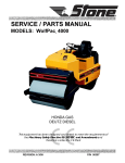
OPERATOR/SERVICE MANUAL MODELS: XH670, XH730, XH840 STOMPER®: 4-Cycle A 100% employee-owned American manufacturer REVISION: E 01/2005 P/N 56642 Table of Contents Stomper® FOREWORD / WARRANTY INFORMATION .......................................................................... 5 LIMITED WARRANTY ................................................................................................................. 6 SECTION 1 - TECHNICAL DATA ............................................................................................... 7 - 12 1.1 Specifications .................................................................................................................... 8 1.2 Engine Specifications ........................................................................................................ 9 1.3 Lubrication Specifications ................................................................................................ 9 1.4 Machine Sound Level Test ................................................................................................ 10 1.5 Components & Controls XH670, XH730 ......................................................................... 11 1.6 Components & Controls XH840....................................................................................... 12 1.7 Components & Controls XH670, XH730, XH840 ........................................................... 12 SECTION 2 - HEALTH & SAFETY - Safety Precautions .......................................................... 13 - 18 SECTION 3 - OPERATION............................................................................................................ 19-22 3.1 Introduction ...................................................................................................................... 20 3.2 Delivery Inspection .......................................................................................................... 20 3.3 Operating Principle .......................................................................................................... 20-21 3.4 Machine Configuration Description ................................................................................. 21 3.5 Before Starting ................................................................................................................. 21 3.5.1 Warnings ........................................................................................................ 21 3.5.2 Pre-Start Checklist ......................................................................................... 21 3.6 To Start Machine .............................................................................................................. 21 3.7 To Stop Machine .............................................................................................................. 21 3.8 Operation of Machine....................................................................................................... 21-22 SECTION 4 - MAINTENANCE ..................................................................................................... 23-32 4.1 Important ....................................................................................................................... 24 4.2 Introduction ...................................................................................................................... 24 4.3 Honda Engine Manuals .................................................................................................... 24 4.4 Engine Oil ....................................................................................................................... 25 4.5 Engine Prefilter and Air Filter .......................................................................................... 25 4.5.1 XH670 & XH730 .......................................................................................... 25 4.5.2 XH840 ........................................................................................................... 25 4.6 Spring Housing Oil ........................................................................................................... 25 4.7 Fuel Tank and Strainer ..................................................................................................... 25 4.8 Fuel Filter ....................................................................................................................... 25 4.9 Fuel Lines ....................................................................................................................... 25 4.10 Spark Plugs ....................................................................................................................... 25 4.11 Engine RPM ..................................................................................................................... 25 4.12 Air Cooling System .......................................................................................................... 26 4.13 Valve Clearance and Combustion Chamber ..................................................................... 26 4.14 Throttle Control Cable Adjustment XH670, XH730 (Honda GX100) ............................ 26 -3- Table of Contents Stomper® 4.15 4.16 4.17 4.18 4.19 4.20 4.21 4.22 4.23 Throttle Control Cable Adjustment XH840 (Honda GX120) .......................................... 27 Throttle Lever Adjustment ............................................................................................... 27 Idle Setting ....................................................................................................................... 27 Air Vent Tube Inspection (XH840 Only) ......................................................................... 27 Fasteners ....................................................................................................................... 27 Base Plate Removal .......................................................................................................... 28 Lower Unit Disassembly .................................................................................................. 29 Loading and Transporting ................................................................................................ 30 Storage Preparation .......................................................................................................... 30-31 4.23.1 Cleaning ......................................................................................................... 31 4.23.2 Fuel ................................................................................................................ 31 4.23.2.1 Adding Fuel Stabilizer ..................................................................... 31 4.24 Storage Precautions .......................................................................................................... 31 4.25 Storing Stompers .............................................................................................................. 31 SECTION 5 - EXPLODED DIAGRAMS AND PARTS LIST ..................................................... 32-59 5.1 Hardware Key .................................................................................................................. 35 5.2 Torque Guidelines and Torque Charts ............................................................................. 36-37 5.3 Gearcase XH670, XH730, XH840 .................................................................................. 38-39 5.4 Lower Unit XH670 .......................................................................................................... 40-43 5.5 Lower Unit XH730, XH840 ............................................................................................ 44-47 5.6 Engine XH670, XH730 Honda GX100 ........................................................................... 48-51 5.7 Engine XH840 Honda GX120......................................................................................... 52-53 5.8 Handle XH670, XH730, XH840 ..................................................................................... 54-57 5.9 Decal Identification ......................................................................................................... 58-59 CALIFORNIA PROPOSITION 65 WARNING ........................................................................... IBC -4- Foreword / Warranty Information Warranty Information These instructions include: Safety regulations Operating instructions Maintenance instructions Please enter the following data. This will help expedite any service or warranty work. These instructions have been prepared for operation on the construction site and for the maintenance engineer. These instructions are intended to simplify operation of the machine and to avoid malfunctions through improper operation. Observing the maintenance instructions will increase the reliability and service life of the machine when used on the construction site and reduce repair costs and downtimes. 1. Machine S/N: ________________________________ 2. 3. VIN: _______________________________________ 4. Purchase Date: _______________________________ 5. Dealer/Distributor Information: Name: ______________________________________ Address: ____________________________________ Only operate the machine as instructed and follow these instructions. Stone Construction Equipment, Inc. is not liable for the function of the machine when used in an improper manner and for other than the intended purpose. Operating errors, improper maintenance and the use of incorrect operating materials are not covered by the warranty. Engine Type: ________________________________ Engine S/N: _________________________________ Always keep these instructions at the place of use of the machine. Observe the safety regulations as well as the guidelines of the civil engineering trade association. Observe the safety rules for the operation of road rollers and compactors and the pertinent regulations for the prevention of accidents. Machine Type: _______________________________ ___________________________________________ Phone #: ____________________________________ Fax #: ______________________________________ 6. Battery Manufacturer: _______________________________ Battery Type: ________________________________ Battery S/N: _________________________________ Location of above information: The above information does not extend the warranty and liability conditions of business of Stone Construction Equipment, Inc. 1. Information on S/N tag. 2. Information on engine tag. 3. Information on S/N tag - if applicable. 4. Date you purchased machine. 5. Dealer machine was purchased from. 6. Information on battery and battery warranty card. Stone Construction Equipment, Inc. P.O. Box 150, Honeoye, New York 14471 Phone: (800) 888-9926 Fax: (585) 229-2363 -5- L i m i t e d W a r r a n t y The Manufacturer warrants that products manufactured shall be free from defects in material and workmanship that develop under normal use for a period of 90 days for concrete vibrators and electric pumps, one year for Rhino®, Bulldog®, WolfPac Rollers, trowels, Stompers®, saws, forward plates, engine powered pumps, Lift Jockey, Mortar Buggy and 6 months for all other products from the date of shipment. The foregoing shall be the exclusive remedy of the buyer and the exclusive liability of the Manufacturer. Our warranty excludes normal replaceable wear items, i.e. gaskets, wear plates, seals, Orings, V-belts, drive chains, clutches, etc. Any equipment, part or product which is furnished by the Manufacturer but manufactured by another, bears only the warranty given by such other manufacturer. (The Manufacturer extends the warranty period to “Lifetime” for the drum bearings and seals for the mortar mixers, and agrees to furnish, free of charge, the bearings and seals only upon receipt of the defective parts. The warranty is two years for eccentric bearings on the forward plate compactors, mortar and plaster mixer drums, trowel gearboxes, three years on the Bulldog trench roller microprocessor (ECIB) and five years on the Bulldog trench roller eccentric bearings.) A Warranty Evaluation Form must accompany all defective parts. Warranty is voided by product abuse, alterations, and use of equipment in applications for which it was not intended, use of non-manufacturer parts, or failure to follow documented service instructions. The foregoing warranty is exclusive of all other warranties whether written or oral, expressed or implied. No warranty of merchantability or fitness for a particular purpose shall apply. The agents, dealer and employees of Manufacturer are not authorized to make modification to this warranty, or additional warranties binding on Manufacturer. Therefore, additional statements, whether oral or written, do not constitute warranty and should not be relied upon. The Manufacturer’s sole responsibility for any breach of the foregoing provision of this contract, with respect to any product or part not conforming to the Warranty or the description herein contained, is at its option (a) to repair, replace or refund such product or parts upon the prepaid return thereof to location designated specifically by the Manufacturer. Product returns not shipped prepaid or on an economical transportation basis will be refused (b) as an alternative to the foregoing modes of settlement - the Manufacturer’s dealer to repair defective units with reimbursement for expenses, except labor, and be reviewed with the Manufacturer prior to repair. A Warranty Evaluation Form must accompany all warranty claims. Except as set forth hereinabove and without limitation of the above, there are no warranties or other affirmations which extends beyond the description of the products and the fact hereof, or as to operational efficiency, product reliability or maintainability or compatibility with products furnished by others. In no event whether as a result of breach of contract or warranty or alleged negligence, shall the Manufacturer be liable for special or consequential damages including but not limited to: Loss of profits or revenues, loss of use of the product or any associated product, cost of capital, cost of substitute products, facilities or services or claims of customers. No claim will be allowed for products lost or damaged in transit. Such claims should be filed with the carrier within fifteen days. Effective January 2004. Stone Construction Equipment, Inc. • 8662 Main Street, P. O. Box 150 • Honeoye, NY 14471-0150 Phone: 1-800-888-9926 • 1-585-229-5141 Fax: 1-585-229-2363 www.stone-equip.com • e-mail: [email protected] -6- P/N 51018 G-7524 01/2004 1. TECHNICAL DATA -7- 1. Technical Data Stomper® ® 1.1 Specifications STONE STOMPERS STONE XH670 STONE XH730 STONE XH840 132 lbs. (60) 144 lbs. (65) 154 lbs. (70) 30.6" x 13.5" x 42" (77,72x34,29x106,68) 29.7" x 14.9" x 42" (75,44x37,85x106,68) 33.8" x 16.4" x 44" (85,85x41,66x111,76) 10" x 13" (25,40 x 33,02) 11" x 13" (27,94 x 33,02) 11" x 13" (27,94 x 33,02) 3 hp Honda (2,24) 3 hp Honda (2,24) 4 hp Honda (2,98) GX100 GX100 GX120 Engine RPM (hz) 4000 (67) 3700 (62) 3600 (60) Fuel Capacity (l) 3 qts. (2,8) 3 qts. (2,8) 3 qts. (2,8) Polyethylene Polyethylene Polyethylene 2650 lbs. (1205) 3100 lbs. (1409) 3500 lbs. (1591) 727 (12) 690 (12) 655 (11) Max. Forward Travel Speed (m/min) 60' - 70' / Min. (18,3 - 21,3) 60' - 70' / Min. (18,3 - 21,3) 60' - 70' / Min. (18,3 - 21,3) Max. Productivity (sq.m/hr) 3500 Sq. Ft./Hr. (325) 3575 Sq. Ft./Hr. (332) 3575 Sq. Ft./Hr. (332) 22”- 25” (55,9-63,5) 22”- 25”(55,9-63,5) 22”- 25”(55,9-63,5) 2.5" (6,4) Up to 3" (7,6) Up to 4" (10,2) Extension, Handle Roller Extension, Handle Roller Extension, Handle Roller MODEL Dimensions Weight (kg) Dimensions L x W x H (cm) Shoe Size (cm) Operating System Power (kW) Engine Specs Fuel Tank Material Performance Impact Force (kg) Max. Blows/Min. (hz) Max. Lift (cm) Max. Amplitude (cm) Options -8- 1. Technical Data Stomper® 1.2 ENGINE SPECIFICATIONS Engine M odel GX100 GX120 Engine Make Honda Honda Engine Type 4-Stroke, Single-Cylinder 4-Stroke, Single-Cylinder Power (kW) 3HP (2.24) 4HP (2.98) Ignition System Transistorized Magneto Transistorized Magneto Fuel Type Unleaded Gasoline 86 octane or higher Unleaded Gasoline 86 octane or higher Fuel Consumption (g/kW h) .54 lb./hp-hr (327) .51 lb./hp-hr (310) Spark Plug CR5HSB BPRGES Spark Plug Gap (mm) .024 - .028 in. (.60 - .70) .028 - .031 in. (.70 - .80) Idle Speed (Hz) 1,850 RPM (31) 1,500 RPM (25) 1.3 LUBRICATION SPECIFICATIONS Engine Crankcase (liter) GX100 GX120 Mobil Delvac 1200 10W30 .30 qt. (.28) Mobil Delvac 1200 10W30 .37 qt. (.40) Spring Housing (liter) Mobil Delvac 1230 10W30 .50 qt. (.47) -9- 1. Technical Data Stomper® 1.4 MACHINE SOUND LEVEL TEST Sound Level Meter Calibration Date: Meter Type: Test Date: March 31, 2004 Simpson Model 886-2 Type 2 March 31, 2004 Test Conditions: Temperature: Ambient Sound: Moisture Limit: Test Site: 52° F (11° C) 53 dba Fast mode Top soil Approximately equal to 50% Honeoye, New York USA Machine Type: Engine Speed: Frequency: Sound Level at Operator Position: XH670 4000 727 86 dba - 10 - XH730 3700 673 94 dba XH840 3600 654 102 dba 1. Technical Data Stomper® 1.5 COMPONENTS & CONTROLS XH670, XH730 Choke Lever (Run) Open - 11 - (Start) Closed 1. Technical Data Stomper® 1.6 COMPONENTS & CONTROLS XH840 (Start) (Run) 1.7 COMPONENTS & CONTROLS XH670, XH730, XH840 Throttle Lever Engine Fuel Stop Switch (Run Position) Slow (Start) Fast (Run) - 12 - 2. HEALTH & SAFETY - 13 - 2. Health & Safety Safety Precautions SAFETY USE These machines are designed to carry out the function of compacting material of the non-cohesive, bituminous and granular varieties. If used correctly they will provide an effective and safe means of compaction and meet the appropriate performance standards. It is essential that the driver/operator of the machine is adequately trained in its safe operation, be authorized to drive it, and have sufficient knowledge of the machine to ensure that it is in full working order, before being put to use. - 14 - 2. Health & Safety Safety Precautions Before using this equipment, study this entire manual to become familiar with its operation. Do not allow untrained or unauthorized personnel, especially children, to operate this equipment. Use only factory authorized parts for service. When warning decals are destroyed or missing, contact the Manufacturer immediately at 1-800-888-9926 for replacement. For the safety of yourself and others, it is imperative that the following rules are observed. Failure to do so may result in serious injury or death. FOLLOW SAFETY INSTRUCTIONS Carefully read all safety messages and decals in this manual and on your machine safety signs. Keep decals in good condition. Replace missing or damaged decals. Be sure new equipment components and repair parts include the current safety signs. Replacement safety signs and decals are available through your dealer. Learn how to operate the machine and how to use controls properly. Do not let anyone operate without instruction. Keep your machine in proper working condition. Unauthorized modifications to the machine may impair the function and/or safety and affect machine life. If you do not understand any part of this manual and need assistance, contact your dealer. Read Operator/Service Manual before operating. UNDERSTAND SIGNAL WORDS A signal word DANGER, WARNING, or CAUTION is used with the safety-alert symbol. DANGER identifies the most serious hazards. DANGER or WARNING safety signs are located near specific hazards. General precautions are listed on CAUTION safety signs. CAUTION also calls attention to safety messages in this manual. This notation appears before warnings in the text. It means that the step which follows must be carried out to avoid the possibility of personal injury or death. These warnings are intended to help the technician avoid any potential hazards encountered in the normal service procedures. We strongly recommend that the reader takes advantage of the information provided to prevent personal injury or injury to others. Follow safety alert symbols and warnings. - 15 - 2. Health & Safety Safety Precautions Keep feet clear of the machines shoe at all times. Be sure no one is in a position to be hit by operators hand or arm during starting. Do not leave the machine running unattended. Keep work area free of bystanders. Do not operate this machine on any surface where it can get out of control. Open flame, fire and smoking prohibited. USE COMMON SENSE WHEN HANDLING FUELS Transport and handle fuel only when contained in approved safety container. Do not smoke when refueling or during any other fuel handling operation. Do not refuel while the engine is running or while it is still hot. If fuel is spilled during refueling, wipe it off from the engine immediately and discard the rag in a safe place. Do not operate the equipment if fuel or oil leaks exist - repair immediately. Never operate this equipment in an explosive atmosphere. Stop engine before refueling. DO NOT operate in an unventilated area. Never operate any gas-powered equipment in a poorly ventilated area or enclosed area. Avoid prolonged breathing of exhaust gases. Never perform any work on this equipment while it is running. Always stop the engine and disconnect the spark plug wire to prevent accidental starting. Keep hands, clothing, and jewelry away from all moving parts. Make sure all safety guards are secured and in proper position. - 16 - 2. Health & Safety Safety Precautions HOT SURFACES Avoid contact with hot exhaust systems and engines. Allow engine to cool before performing any repairs or service Use unleaded gasoline, octane rating of 86 or higher. Ear protection required when operating this equipment. Exposure to loud noise can cause impairment or loss of hearing. Check the engine oil level before starting. PREPARE FOR EMERGENCIES Be prepared if a fire starts. Keep a first aid kit and fire extinguisher handy. Keep emergency numbers for doctors, ambulance service, hospital, and fire department near your telephone. WEAR PROTECTIVE CLOTHING Wear close fitting clothing and safety equipment appropriate to the job. Prolonged exposure to loud noise can cause impairment or loss of hearing. Wear a suitable hearing protective device such as earmuffs or earplugs to protect against objectionable or uncomfortable loud noises. Operating equipment safely requires the full attention of the operator. Do not wear radio or music headphones while operating machine. - 17 - 2. Health & Safety Safety Precautions Starting fluid (ether) is highly flammable, do not use or an explosion or fire may result. PRACTICE SAFE MAINTENANCE Understand service procedure before doing work. Keep area clean and dry. Never lubricate, service or adjust machine while it is moving. Keep hands, feet, and clothing from power-driven parts. Disengage all power and operate controls to relieve pressure. Lower equipment to the ground. Stop the engine. Remove the key. Allow machine to cool. Securely support any machine elements that must be raised for service work. Keep all parts in good condition and properly installed. Fix damage immediately. Replace worn or broken parts. Remove any buildup of grease, oil, or debris. Disconnect battery ground cable (-) before making adjustments on electrical systems or welding on machine. DISPOSE OF WASTE PROPERLY Improperly disposing of waste can threaten the environment and ecology. Potentially harmful waste used with equipment include such items as oil, fuel, coolant, brake fluid, filters, and batteries. Use leakproof containers when draining fluids. Do not use food or beverage containers that may mislead someone into drinking from them. Do not pour waste onto the ground, down a drain, or into any water source. Air conditioning refrigerants escaping into the air can damage the Earths atmosphere. Government regulations may require a certified air conditioning service center to recover and recycle used air conditioning refrigerants. Inquire on the proper way to recycle or dispose of waste from your local environmental or recycling center. - 18 - 3. OPERATION - 19 - 3. Operation 3.1 INTRODUCTION serviced independently without total machine disassembly. Over the long-term, this exclusive feature cuts service costs and lowers lifetime costs. Congratulations on your purchase of a Stone Stomper! Youve made an excellent choice! Three models of 4-cycle rammers deliver maximum impact force, yet are light-weight, smooth running and easy to operate. Stompers are powered by 4-cycle Honda engines that have been designed to take a beating and meet the toughest EPA standards. Stone Stompers unique design combines precise spring force, crank throw and weight to produce maximum impact force. Plus, exclusive operator-friendly features and superior balance make Stone Stompers effortless to operate. Comfort and Control A unique, state-of-the-art snap-on, contoured cover reduces noise and protects the engine yet allows easy access for servicing. A heavy-duty ergonomic throttle puts more comfortable control at your finger tips for easy operation. Weve reduced operator fatigue with an extra-padded hand grip and superior rubber shock mountings. Their lighter weight makes them perfect for easy transport, with the added convenience of heavy-duty lifting handles and optional transport wheels. Precision Built to Last Stompers are built to last with precision components. Everywhere theres durability: forged steel crank and rod, quadruple fuel filtration, heavy-duty throttle, solid snubbers, self-aligning centrifugal clutch and a highvolume, two-stage air cleaner. Stompers are equipped with a convenient fuel shut off valve to quickly and easily shut the fuel flow to the engine. Modular Design This exclusive, innovative, high-tech design totally revolutionizes rammer servicing. The top and bottom modules detach from the boot in minutes, cutting service time virtually in half. Each module can be Muscle out the competition with Stone Stompers. 3.2 DELIVERY INSPECTION Upon receipt of your Stomper, CAREFULLY CHECK FOR ANY FREIGHT DAMAGE. Any damage should be immediately reported to the carrier and a claim registered. Stone Stompers are manufactured to the strictest specifications and inspection procedures. If any material or manufacturing defects are found, return the tag on the machine with the assemblers signature and your findings to the manufacturer. We want to know when a product is less than perfect. We also welcome any and all input on how the product may serve you better. The following instructions were compiled to provide you information on how to obtain long and trouble-free use of the unit. Periodic maintenance of this unit is essential. Read the manual in its entirety and follow the instructions carefully. Failure to do so may injure yourself or a bystander. 3.3 OPERATING PRINCIPLE A tamping shoe is mounted at the lower end of a cylindrical spring housing. A piston, installed between massive opposing springs inside the spring housing, is actuated by a connecting rod and crank system, which is driven by a high speed 4-cycle gasoline engine through a gear train and centrifugal clutch. The piston alternately loads and unloads the springs. This results in a rapid lifting up and ramming down action of the tamping shoe to compact the underlying material. The Stomper is effective for compaction of a wide variety of job soil substances, particularly clay lumps, silt, loam and all granular materials. Although relatively light in weight and easy to operate, the Stomper delivers a tremendous impact to the soil. - 20 - 3. Operation These instructions contain information to guide you in efficient use and proper maintenance of the Stomper. To get long and trouble-free service from this power tool, periodic maintenance of the engine and machine is essential. The Stomper is shipped completely assembled and only requires filling with 4-cycle motor oil and regular unleaded gasoline as well as a brief check of lubricant levels in preparation for operation. You should first study these instructions. 3.4 MACHINE CONFIGURATION DESCRIPTION 4-cycle Stone Stompers are supplied in three models: XH670 - Light XH730 - Medium XH840 - Heavy 3.5 BEFORE STARTING 3.6 TO START MACHINE Read Operator Manual before operating machine. Open air vent on gas tank by turning counterclockwise. Turn engine fuel stop switch to run position. Set choke to close position. Note: A warm engine may not require choke. Set throttle lever to slow position. Pull the starter grip briskly once or twice to start the engine, continue to pull as necessary to start. When engine starts, let the engine run at idle to warm up then return choke to open position. Move throttle to fast position for operation. 3.7 TO STOP MACHINE Review the following information. Specific information regarding these items can be found in the Technical Data Section or located from the Table of Contents. Move throttle lever to slow, allow engine to idle before stopping. 3.5.1 Warnings To stop the engine, turn the engine fuel stop switch to stop position. Fuel is highly flammable, handle with care. Do not refuel the engine while smoking or when near an open flame or sparks. Always stop engine before refueling. Clean up spilled fuel before starting. Avoid fires by keeping engine clean of accumulated grease and debris. Do not run unit in enclosed, unventilated areas. Avoid prolonged breathing of exhaust gases. 3.5.2 Pre-Start Checklist Check engine oil level. Check air filter elements. Check spring housing oil level. Check fuel level. 3.8 OPERATION OF MACHINE WARNING WHEN OPERATING THE STOMPER, KEEP FEET CLEAR FROM THE RAMMING SHOE. SERIOUS PERSONAL INJURY MAY OCCUR. WHEN OPERATING THE STOMPER, HEARING PROTECTION SHOULD BE WORN. HEARING LOSS MAY RESULT FROM PROLONGED EXPOSURE TO NOISE. CAUTION: Never operate on hard, unyielding surfaces. Unwarranteed damage may result. CAUTION: Always use both hands when operating this machine. This will ensure safe machine operation. - 21 - 3. Operation In operation, guide the machine but let the machine do the work. Bearing down on the handle unnecessary and limits the shoe jump. On nearly level surfaces, the machine moves forward in rapid jumps. On uneven surfaces or inclines, rocking the handle slightly may assist the Stomper in moving forward. Always guide the Stomper so that the whole shoe, and not just the front or back edge, does the impacting. As the soil becomes compacted, the jump height of the Stomper will increase. After a brief experience, you will know how to adapt the technique to the job conditions. - 22 - 4. MAINTENANCE - 23 - 4. Maintenance F Stomper® 4.1 IMPORTANT The person attempting any of the following maintenance tasks must be authorized to do so and have read and understood all sections within this manual. 4.2 INTRODUCTION The following instructions were compiled to provide you information on how to obtain long and trouble-free use of the unit. Periodic maintenance of this unit is essential. Read the Operator/Service Manual in its entirety and follow the Health & Safety Precautions carefully. Failure to do so may injure yourself, a bystander or the environment. 4.3 HONDA ENGINE MANUALS Read and understand the Honda Engine Owners Manual (provided with the Stone Stomper) prior to operation and service. 56649 Manual Owners Honda GX100 56650 Manual Owners Honda GX120 For more detailed service information, see the Honda Engine Shop manual (not provided). - 24 - 56651 Manual Shop Honda GX100 56652 Manual Supplement Honda GX100 56660 Manual Shop Honda GX120 56661 Manual Supplement Honda GX120 4. Maintenance Stomper® 4.4 ENGINE OIL 1. With unit standing upright (in vertical position, not operating) so that the oil drains freely into the spring housing, check that the oil is at fill sight plug level. Check engine oil level daily before operation. Change after the first 20 hours, then every 100 hours (see Technical Data Section for lubrication specifications). 2. Whenever the level is low, remove the fill sight plug and refill until oil runs out of sight plug hole, replace sight plug. Check that oil is at sight plug level. Check engine oil level with the machine on a level surface with the engine stopped. NOTICE: Running the engine with a low oil level can cause engine damage. NOTE: Use of a socket wrench is recommended to avoid damage to the sight gauge. 4.5 ENGINE PREFILTER AND AIR FILTER 4.7 FUEL TANK AND STRAINER Replace elements every 100 hours, more frequently in dusty conditions. Check fuel level daily before operation. Clean tank and strainer every 100 hours, replace if damaged (see Technical Data Section for fuel specifications). Drain and flush the fuel tank yearly. 4.5.1 XH670 & XH730 Clean prefilter on top and air filter on side of engine. Wash foam element with detergent and water. Dry the element by squeezing between towels. Tap paper element on a hard surface to remove dirt. Do not oil elements. 4.8 FUEL FILTER Check every 100 hours. Replace if water or dirt sediment is found or replace yearly. 4.9 FUEL LINES 4.5.2 XH840 Wash foam element with detergent and water. Dry the element by squeezing between towels. Apply clean engine oil to foam element and squeeze out excess oil. Tap paper element on a hard surface to remove dirt. 4.6 SPRING HOUSING OIL Check daily before operation. Change after the first 20 hours, then every 300 hours (see Technical Data Section for lubrication specifications). Oil Fill Plug and Sight Gauge Inspect fuel line and clamps weekly. Replace if damaged or replace every 2 years. 4.10 SPARK PLUGS Check/clean every 100 hours. Replace if damaged or replace yearly. (See Technical Data Section for engine specifications for spark plug and gap). 4.11 ENGINE RPM Check/adjust every 100 hours (see Technical Data Section for machine specifications). NOTICE: The engine RPM setting should not be modified or severe engine or machine damage may occur. - 25 - 4. Maintenance Stomper® 4.12 AIR COOLING SYSTEM 4.15 THROTTLE CONTROL CABLE ADJUSTMENT XH840 (Honda GX120) Clean machine daily. The recoil starter screen and the engine cooling fins should be free of debris to allow proper cooling for the engine. 1. Loosen the throttle clamp screw. 4.13 VALVE CLEARANCE AND COMBUSTION CHAMBER These items should be service by your servicing dealer after 300 hours unless you have the proper tools and are mechanically proficient. Refer to Honda shop manual for service procedures. 4.14 THROTTLE CONTROL CABLE ADJUSTMENT XH670, XH730 (Honda GX100) 1. Loosen the throttle clamp screw and the lock nut on the high RPM adjusting bolt. 2. To increase engine RPM turn the high RPM adjusting screw counterclockwise. To decrease engine RPM turn the high RPM adjusting screw clockwise. 3. Move the throttle lever to the fast position, rotate and hold the engine throttle against the high RPM adjusting bolt and tighten the throttle cable clamp screw. 4. Run machine and check engine RPM (see Technical Data Section for specified RPM). 2. To increase engine RPM turn the high RPM adjusting screw counterclockwise. To decrease engine RPM turn the high RPM adjusting screw clockwise. 3. Move the throttle lever to the fast position, rotate and hold the engine throttle against the high RPM adjusting bolt and tighten the throttle cable clamp screw. High RPM Adjusting Screw Throttle Cable Clamp Screw 4. Run machine and check engine RPM (see Technical Data Section for specified RPM). - 26 - 4. Maintenance Stomper® 4.16 THROTTLE LEVER ADJUSTMENT Retighten pivot bolt tight enough as to not allow throttle lever to move forward when machine is operating. 4.17 IDLE SETTING 4.18 AIR VENT TUBE INSPECTION (XH840 Only) Check that the air vent tube is secured by the tube retainers without collapsing or kinking. If the engine idles smoothly but at too high RPM, turn the idle stop screw counterclockwise a little at a time until the desired specification is obtained. To increase the speed, turn the idle stop screw slowly clockwise until the desired RPM is obtained (see Technical Data Section for specified RPM). The idle stop screw is the black screw located behind the air cleaner base plate. 4.19 FASTENERS Check all nuts and bolts after 4 hours, then every day of operation. Torque values for fasteners are found in the appropriate part drawings located in the back section of this manual Start the engine and allow it to warm up to normal operating temperature. With the engine idling, turn the throttle stop screw to obtain the standard idle speed. - 27 - 4. Maintenance Stomper® 4.20 BASE PLATE REMOVAL WARNING The spring retaining Base Plate retains heavy springs under compression. Follow the instructions carefully or severe personal injury may occur. Detach shoe by removing six (6) shoe bolts and washers. Assemble two (2) threaded bolts, two (2) washers from bottom two corner bolt holes, fully thread two (2) nuts with two (2) washers from opposite side. WITH CAUTION, remove the four (4) sock head cap screws and then alternately back off the two thread rods approximately 1/2 inch at a time until all the spring tension is removed, then remove the threaded bolts and base plate to access springs. ITEM P/N DESCRIPTION Kit 23011 (includes all) Tool Kit, Base Plate Removal 1 1 2 3 4 43150 80896 80807 56230 Full Thread Bolt M12 x 8" NUTFX M12 WSHR M12 x 2400 Instructions Base Plate Removal 2 2 4 1 - 28 - QUANTITY 4. Maintenance Stomper® 4.21 LOWER UNIT DISASSEMBLY The spring retaining Base Plate retains heavy springs under compression. Follow the instructions carefully or severe personal injury may occur. WARNING 1. Detach the shoe from the Stomper by removing (6) shoe bolts and washers. 2. Thread M8 nuts onto (2) full thread M8 x 5.50 bolts (provided in kit) 1.25 up from the bottom of the bolts (see Figure A). 3. Replace two bolts that are diagonal from each other on the bottom spring cover with assembled full thread bolts with nuts from Step 2. Make sure to thread the assembled bolts in a full 1.25 (see Figure B). 4. Remove the other (4) bolts from the bottom spring cover (leaving the full thread bolts in place). 5. Carefully back each nut off a .25 at a time on each side using two wrenches (one to hold the bolt in place and the other to back the nut off) until the spring tension is removed (see Figure C). 6. Then remove the full thread bolts and the bottom spring cover to access the springs. 7. Remove lower spring set. 8. Insert snubber puller, P/N 39539, under snubber (Item 14). Insert pry bar under snubber puller and pop loose snubber. 9. Using M24 deep socket, remove M16NY locknut from piston rod. Insert 5/8" or smaller rod through top of piston rod head to hold rod from turning to remove nut. 10. Piston puck and upper springs can now be accessed. 11. Reassemble in reverse order. * Use red loctite 264 on shoe bolts only. Figure A Figure B Figure C ITEM P/N DESCRIPTION KIT 1 2 3 4 23159 56338 50107 39539 80854 Kit Snubber Puller XN Instructions Lower Unit Service XN Weld Thread M8 x 5.50 in. Puller Snubber NUTFX M8-1/25 - 29 - QUANTITY 1 1 2 1 2 4. Maintenance Stomper® 4.22 LOADING AND TRANSPORTING 4.23 STORAGE PREPARATION If the engine has been running, allow it to cool for at least 15 minutes before storing or loading on the transport vehicle. A hot engine and muffler can burn you and can ignite some materials. Close the air vent on the gas tank by turning clockwise. Check that the engine fuel stop switch is in the stop position. See Technical Data Section for machine sizes and weights. Use properly rated tie downs, chains and lifting equipment. Proper storage preparation is essential for keeping your Stomper trouble-free and looking good. The following steps will help to keep rust and corrosion from impairing your engines function and appearance, and will make the engine easier to start when you use it again. 4.23.1 Cleaning If the engine has been running, allow it to cool for at least an hour before cleaning. Clean all exterior surfaces, touch up any damaged paint and coat other areas that may rust with a light film of oil. WARNING GASOLINE IS BOTH TOXIC AND FLAMMABLE. DO NOT SMOKE WHILE WORKING WITH FUEL. DO NOT USE NEAR OPEN FLAME. AVOID PROLONGED BREATHING OF VAPORS AND SKIN CONTACT. FLASH POINT OF GASOLINE IS 40° F (4° C). SERIOUS ILLNESS OR LOSS OF LIFE COULD RESULT. NOTICE: Using a garden hose or pressure washing equipment can force water into the air cleaner or muffler opening. Water in the air cleaner will soak the air filter and water that passes through the air filter or muffler can enter the cylinder causing damage. ATTACH LIFT EQUIPMENT TO MACHINE LIFTEYE ONLY. USE CAUTION WHEN LOADING, MACHINE MAY SWING, TIP, SLIDE OR FALL. DO NOT STAND UNDER MACHINE WHEN LIFTING OR LOADING. Transport the machine as shown. Always secure the machine in transport. Secure machine so it does not slide, tip or move. Water contacting a hot engine can cause damage. If the engine has been running, allow it to cool for at least an hour before washing. 4.23.2 Fuel Gasoline will oxidize and deteriorate in storage. Old gasoline will cause hard starting and it leaves gum deposits that clog the fuel system. If the gasoline in your engine deteriorates during storage, you may need to have the carburetor and other fuel system components serviced or replaced. The length of time that gasoline can be left in your fuel tank and carburetor without causing functional problems will vary with such factors as gasoline blend, your storage temperatures and whether the fuel tank is partially or completely filled. The air in a partially filled fuel tank promotes fuel deterioration. Very warm storage/temperatures accelerate fuel deterioration. Fuel deterioration problems may occur within a few months or even less if the gasoline was not fresh when you filled the fuel tank. - 30 - 4. Maintenance Stomper® You can extend fuel storage life by adding a fuel stabilizer that is formulated for the purpose, or you can avoid fuel deterioration problems by draining the fuel tank and carburetor. 4.23.2.1 Adding Fuel Stabilizer When adding a fuel stabilizer, fill the fuel tank with fresh gasoline. If only partially filled, air in the tank will promote fuel deterioration during storage. If you keep a container of gasoline for refueling, be sure that it contains only fresh gasoline. 4.25 STORING STOMPERS The following steps should be taken to prepare your Stomper for storage: 1. Disconnect fuel line and allow all fuel to drain from the gasoline tank only. Replace fuel line. 2. Start engine and allow to run until it stops from lack of fuel. This will use up all the fuel in the carburetor and prevent the formation of deposits due to evaporation of fuel. 1. Add fuel stabilizer following the manufacturers instructions. WARNING GASOLINE IS BOTH TOXIC AND FLAMMABLE. DO NOT SMOKE WHILE WORKING WITH FUEL. DO NOT USE NEAR OPEN FLAME. AVOID PROLONGED BREATHING OF VAPORS AND SKIN CONTACT. FLASH POINT OF GASOLINE IS 40° F (4° C). SERIOUS ILLNESS OR LOSS OF LIFE COULD RESULT. 2. After adding a fuel stabilizer, run the engine outdoors for 10 minutes to be sure that treated gasoline has replaced the untreated gasoline in the carburetor. 3. Stop the engine 4.24 STORAGE PRECAUTIONS If your engine will be stored with gasoline in the fuel tank and carburetor, it is important to reduce the hazard of gasoline vapor ignition. Select a well-ventilated storage area away from any appliance that operates with a flame, such as a furnace, water heater or clothes dryer. Also avoid any area with a spark-producing electric motor or where power tools are operated. If possible, avoid storage areas with high humidity because that promotes rust and corrosion. 4. Remove spark plug and pour 60cc or 2 ounces (1/4 cup) of motor oil into the cylinder. 5. Crank the engine two or three times to distribute the oil throughout the cylinder. This will help prevent rusting during storage. 6. Replace spark plug. Unless all fuel has been drained from the fuel tank, leave the fuel valve in the CLOSED or OFF position to reduce the possibility of fuel leakage. Position the equipment so the engine is level. Tilting can cause fuel or oil leakage. 3. Check that the engine fuel stop switch is in the stop position. 7. Pull the starter role slowly until resistance is felt and the notch on the starter pulley aligns with the hole at the top of the recoil starter cover. This will close the valves so moisture cannot enter the engine cylinder. Return the starter rope gently. 8. Store the unit in an upright position (as in the operating position) in a cool, dry, ventilated area. - 31 - - 32 - 5. EXPLODED VIEWS WITH PARTS - 33 - 5. Parts List Exploded Views with Parts 5.1 Hardware Key .................................................................................................................. 37 5.2 Torque Guidelines and Torque Charts ............................................................................. 38-39 5.3 Gearcase XH670, XH730, XH840 .................................................................................. 40-41 5.4 Lower Unit XH670 .......................................................................................................... 42-45 5.5 Lower Unit XH730, XH840 ............................................................................................ 46-49 5.6 Engine XH670, XH730 Honda GX100 ........................................................................... 50-53 5.7 Engine XH840 Honda GX120......................................................................................... 54-55 5.8 Handle XH670, XH730, XH840 ..................................................................................... 56-59 5.9 Decal Identification ......................................................................................................... 60-61 - 34 - 5. Parts List 5.1 HARDWARE KEY ZN = ZINC PLATED BLK = BLACK OXIDE FINISH - 35 - 5. Parts List 5.2 Torque Charts 5.2 TORQUE GUIDELINES DO NOT use these values if a different torque value or tightening procedure is given for a specific application. Torque values listed are for general use only. Check tightness of fasteners periodically. Shear bolts are designed to fail under predetermined loads. Always replace shear bolts with identical grade. Fasteners should be replaced with the same or higher grade. If higher grade fasteners are used, these should only be tightened to the strength of the original. Make sure fasteners threads are clean and that you properly start thread engagement. This will prevent them from failing when tightening. SAE GRADE 5 Coarse Thread, Zinc-Plated SIZE 1/4 - 20 (.250) 5/16 - 18 (.3125) 3/8 - 16 (.375) 7/16 - 14 (.4375) 1/2 - 13 (.500) 9/16 - 12 (.5625) 5/8 - 11 (.625) 3/4 - 10 (.750) 7/8 - 9 (.875) 1 - 8 (1.000) SAE GRADE 8 Coarse Thread, Zinc-Plated TORQUE ft. lbs. Nm 6 8 13 18 23 31 37 50 57 77 82 111 112 152 200 271 322 436.5 483 655 SIZE 1/4 - 20 (.250) 5/16 - 18 (.3125) 3/8 - 16 (.375) 7/16 - 14 (.4375) 1/2 - 13 (.500) 9/16 - 12 (.5625) 5/8 - 11 (.625) 3/4 - 10 (.750) 7/8 - 9 (.875) 1 - 8 (1.000) SAE GRADE 5 Fine Thread, Zinc-Plated SIZE 1/4 - 28 (.250) 5/16 - 24 (.3125) 3/8 - 24 (.375) 7/16 - 20 (.4375) 1/2 - 20 (.500) 9/16 - 18 (.5625) 5/8 - 18 (.625) 3/4 - 16 (.750) 7/8 - 14 (.875) 1 - 12 (1.000) 1 -14 (1.000) TORQUE ft. lbs. Nm 9 12 18 24 33 45 52 70 80 108 115 156 159 215 282 382 454 615 682 925 SAE GRADE 8 Fine Thread, Zinc-Plated TORQUE ft. lbs. Nm 7 10 14 19 26 35 41 56 64 87 91 123 128 173 223 302 355 481 529 717 541 733 SIZE 1/4 - 28 (.250) 5/16 - 24 (.3125) 3/8 - 24 (.375) 7/16 - 20 (.4375) 1/2 - 20 (.500) 9/16 - 18 (.5625) 5/8 - 18 (.625) 3/4 - 16 (.750) 7/8 - 9 (.875) 1 - 12 (1.000) 1 -14 (1.000) t-chrt_i.doc - 36 - TORQUE ft. lbs. Nm 10 14 20 27 37 50 58 79 90 122 129 175 180 244 315 427 501 679 746 1011 764 1036 5. Parts List 5.2 Torque Charts Property Class 8.8 ZINC-PLATED SIZE M6 M8 M10 M12 M14 M16 M20 M24 Coarse Thread Nm ft. lbs. 9.9 7 24 18 48 35 83 61 132 97 200 148 390 288 675 498 Fine Thread Nm ft. lbs. 10 7 25 18 49 36 88 65 140 103 210 155 425 313 720 531 Property Class 10.9 ZINC-PLATED SIZE M6 M8 M10 M12 M14 M16 M20 M24 Coarse Thread Nm ft. lbs. 14 10 34 25 67 49 117 86 185 136 285 210 550 406 950 701 Fine Thread Nm ft. lbs. 14 10 35 26 68 50 125 92 192 142 295 218 600 443 1000 738 Property Class 12.9 ZINC-PLATED SIZE M6 M8 M10 M12 M14 M16 M20 M24 Coarse Thread Nm ft. lbs. 16.5 12 40 30 81 60 140 103 220 162 340 251 660 487 1140 841 Fine Thread Nm ft. lbs. 16.5 12 42 31 82 60 150 111 235 173 350 258 720 531 1200 885 Conversion Factor: 1 ft. lb. = 1.3558 Nm - 37 - 5. Parts List 5.3 Gearcase XH670, XH730, XH840 - 38 - 5. Parts List 5.3 Gearcase XH670, XH730, XH840 - 39 - 5. Parts List 5.4 Lower Unit XH670 - 40 - 5. Parts List 5.4 Lower Unit XH670 - 41 - 5. Parts List 5.4 Lower Unit XH670 Contd. - 42 - 5. Parts List 5.4 Lower Unit XH670 Contd. ^ Not Shown - 43 - 5. Parts List 5.5 Lower Unit XH730, XH840 - 44 - 5. Parts List 5.5 Lower Unit XH730, XH840 - 45 - 5. Parts List 5.5 Lower Unit XH730, XH840 Contd. - 46 - 5. Parts List 5.5 Lower Unit XH730, XH840 Contd. - 47 - 5. Parts List 5.6 Engine XH670, XH730 Honda GX100 - 48 - 5. Parts List 5.6 Engine XH670, XH730 Honda GX100 - 49 - 5. Parts List 5.6 Engine XH670, XH730 Honda GX100 Contd. - 50 - 5. Parts List 5.6 Engine XH670, XH730 Honda GX100 Contd. - 51 - 5. Parts List 5.7 Engine XH840 Honda GX120 - 52 - 5. Parts List 5.7 Engine XH840 Honda GX120 - 53 - 5. Parts List 5.8 Handle XH670, XH730, XH840 - 54 - 5. Parts List 5.8 Handle XH670, XH730, XH840 - 55 - 5. Parts List 5.8 Handle XH670, XH730, XH840 Contd. - 56 - 5. Parts List 5.8 Handle XH670, XH730, XH840 Contd. - 57 - 5. Parts List 5.9 Decal Identification 2 1 3 (side 1) 3 (side 2) 5 4 6 7 12 8 10 11 9 - 58 - 13 5. Parts List Item 5.9 Decal Identification P/N Description 1 2 55485 55527 Tag Switch Stop Decal Instruction Air Filter 1 1 3 4 55528 55214 Tag Safety Warning Decal Sta-bil 1 1 5 6 55529 55530 Decal Instruction Throttle Decal Instruction Operation 1 1 7 8 55531 55533 Decal Instruction RPM XH670 Decal Instruction RPM XH730 1 1 9 10 55532 55535 Decal Instruction RPM XH840 Decal Warning Springs 1 1 11 12 55541 55536 Decal Instruction Notice Decal Instruction Oil Level 1 1 13 55543 Decal Instruction Choke 1 - 59 - Quantity CALIFORNIA PROPOSITION 65 WARNING: Operation of this equipment and/or engine exhaust from this product contains chemicals known to the State of California to cause cancer, birth defects, and other reproductive harm. Stone Construction Equipment, Inc. P.O. Box 150, Honeoye, New York 14471 Phone: (800) 888-9926 Fax: 585-229-2363 e-mail: [email protected] www: stone-equip.com A 100% employee-owned American manufacturer © 2004 Stone Construction Equipment, Inc. Printed in U.S.A. SPR