1
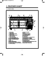
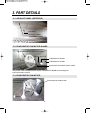
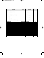
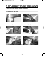
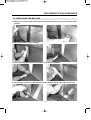
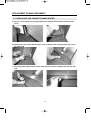
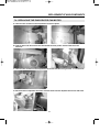
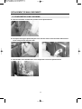
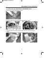
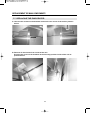
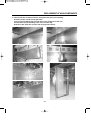
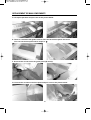
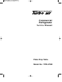
Commercial
Refrigerator
Service Manual
Pizza Prep Table
Model No.: TPR-67SD
TABLE OF CONTENTS
1. FEATURE CHART
1-1. FRONT VIEW
1-2. PLAN VIEW AND SIDE VIEW
2. WIRING DIAGRAM
2-1. TPR-67SD
3. PART DETAILS
3-1. DUCT PANEL (EXTERIOR)
3-2. EVAPORATOR FAN MOTOR GUARD
3-3. EVAPORATOR FAN MOTOR ASSEMBLY
3-4. EVAPORATOR COIL
3-5. AIR GUIDE PANEL & PAD
3-6. DUCT PANEL (INTERIOR)
3-7. CABINET FRONT COVER
3-8. THERMOSTAT & POWER SWITCH
3-9. CONDENSER COIL
3-10. CONDENSER FAN MOTOR ASSEMBLY
3-11. COMPRESSOR COMPARTMENT PART (FRONT)
3-12. COMPRESSOR COMPARTMENT PART (BACK)
4. MAIN COMPONENTS
4-1. COMPRESSOR
4-2. COMPRESSOR RELAY, OVERLOAD
4-3. COMPRESSOR CAPACITOR
4-4. CONDENSER FAN MOTOR
4-5. EVAPORATOR FAN MOTOR
4-6. SWITCH
5. ELECTRONIC CONTROLLER INSTRUCTION
5-1. HOW TO USE THE TEMPERATURE CONTROL
5-2. FUNCTION TABLE
6. SPARE PARTS LIST
7. REPLACEMENT OF MAIN COMPONENTS
7-1. REPLACING THE DOOR
7-2. REPLACING THE MULLION
7-3. REPLACING THE CABINET FRAME HEATER
7-4. REPLACING THE EVAPORATOR FAN MOTOR
7-5. EVAPORATOR LEAK CHECKING
7-6. REPLACING THE COMPRESSOR COMPARTMENT PART
7-7. REPLACING THE EVAPORATOR
1
1. FEATURE CHART
1-1. FRONT VIEW
2
FEATURE CHART
1-2. PLAN VIEW AND SIDE VIEW
3
2. WIRING DIAGRAM
TPR-67SD
4
3. PART DETAILS
3-1. AIR DUCT PANEL (EXTERIOR)
PAN DUCT
AIR DUCT PANEL
(LOUVERED PANEL)
3-2. EVAPORATOR FAN MOTOR GUARD
EVAPORATOR FAN MOTOR GUARD
POWER SWITCH
THERMOSTAT KNOB
THERMOSTAT PANEL
EVAPORATOR FRONT DUCT PANEL
The position of the POWER SWITCH and the THERMOSTAT KNOB can be changed for
improvement without notice.
3-3. EVAPORATOR FAN MOTOR
EVAPORATOR
FAN MOTOR
EVAPORATOR FAN BLADE
Bracket
5
PART DETAILS
3-4. EVAPORATOR COIL
FIN
INLET
OUTLET
ACCUMULATOR
3-5. AIR GUIDE PANEL & PAD
AIR GUIDE PANEL (B)
AIR GUIDE PANEL (C)
AIR GUIDE PANEL (A)
AIR GUIDE PAD (E-PS)
3-6. DUCT PANEL (INTERIOR)
PAN DUCT
AIR DUCT PANEL
(LOUVERED PANEL)
AIR FLOW
6
PART DETAILS
3-7. CABINET FRONT COVER
CABINET FRONT COVER
CONDENSER COIL
3-8. THERMOSTAT & POWER SWITCH
THERMOSTAT
POWER SWITCH
3-9. CONDENSER COIL
INLET
OUTLET
BRACKET
FIN
7
PART DETAILS
3-10. CONDENSER FAN MOTOR
CONDENSER FAN MOTOR
CONDENSER FAN BLADE
BRACKET
3-11. COMPRESSOR COMPARTMENT PART (FRONT)
CONNECTING PIPE (A)
CONNECTING PIPE (B)
COMPRESSOR
CONDENSER COIL
CONDENSER FAN MOTOR
3-12. COMPRESSOR COMPARTMENT PART (BACK)
SUCTION LINE (B)
SUCTION LINE FIXTURE
8
4. MAIN COMPONENTS
4-1. COMPRESSOR
MODEL
PART NAME
PART NO.
HORSE
POWER
CAPACITY
TYPE OF
MOTOR
INPUT
MAKER
TPR-67SD
T6217Z
3020014570
5/8HP
7,638.4BTU/h
(1,925Kcal/h)
CSIR
-
EMBRACO
4-2. COMPRESSOR RELAY, OVERLOAD
MODEL
RELAY
PART NO. OVERLOAD PART NO.
MRT00AFW-3187
TPR-67SD 9660-A-041-191
MAKER
EMBRACO
NOTE
MAKER
-
NOTE
-
4-3. COMPRESSOR CAPACITOR
MODEL
STARTING
PART NO.
TPR-67SD 330V 189~227µF Comp. Assembly
RUNNING
PART NO.
-
4-4. CONDENSER FAN MOTOR
MODEL
PART NAME
PART NO. POLE
TPR-67SD IS4420DWSG-1 3963220410
INPUT
4P
47W
BLADE
MAKER
(NUMBER)
Shaded Pole
AL
SUNGSHIN
Induction
4
TYPE
4-5. EVAPORATOR FAN MOTOR
MODEL
PART NAME
PART NO. POLE
TPR-67SD IS4420DWSN-2A 3963328120
INPUT
4P
47W
BLADE
MAKER
(NUMBER)
Shaded Pole
AL
SUNGSHIN
Induction
5
TYPE
4-6. SWITCH
PART NAME
POWER SWITCH (ROCKER SWITCH)
THERMOSTAT
PART NO.
30281Q0100
30283M0100
9
RATING
125V/15A
K55Q-5608, 16A
MAKER
SKT
RANGCO
5. TEMPERATURE CONTROL INSTRUCTION
5-1. HOW TO USE THE TEMPERATURE CONTROL
- Temperature can be controlled by the user.
- Factory setting is at ‘NORMAL’. Settings can be
changed by Dial Knob.
- Indicates temperature
level setting.
COOL
OFF
NORMAL
COLD
TEMPERATURE CONTROL
(TPR-67SD)
5-2. FUNCTION TABLE
No
1
Function
Controlled
Part
Description
1. The temperature can be changed by turning the dial knob.
Temperature
Compressor
Control
Cond. Fan Motor 2. Compressor is automatically turned on and off by thermostat.
(K55Q-5608)
■ Cut in and out temperature chart. ˚F
Model: TPR-67SD
No.
Cool
Normal
Cold
Cut in
Cut Out
21.2
10
40.1 ± 2.7
17.1
10.4
6. PARTS-LIST OF PIZZA PREP TABLE
Part name
Caster
CASTER
CASTER BRAKE
Door
DOOR ASSEMBLY(LEFT)
DOOR ASSEMBLY(RIGHT)
DOOR GASKET
DOOR BUSHING
DOOR HINGE TOP(LEFT)
DOOR HINGE TOP(RIGHT)
DOOR HINGE BOTTOM(LEFT)
DOOR HINGE BOTTOM(RIGHT)
DOOR HINGE SPRING
COMPRESSOR COMPARTMENT
CONDENSER COIL
SUCTION LINE (A)
COMPRESSOR BASE
COMPRESSOR
POWER CORD
FRONT GRILLE PANEL
REAR GRILLE
COMPRESSOR DRYER
DRAIN PAN
DRAIN PAN HOUSING
DRAIN HOSE
CONDENSER FAN MOTOR
CONDENSER FAN BLADE
CONNECTING PIPE
CONNECTING PIPE (DELIVERY PIPE)
CAPILLARY TUBE
SUCTION LINE (B)
COMPRESSOR HARNESS ASSEMBLY
REFRIGERATION COMPARTMENT
MULLION COVER
MULLION HEATER
CABINET FRAME HEATER
Code
Description
Model
TPR-67SD
30265L0400
30265L0300
TP5040-21-HDP
TP5040-21-HDP-TLB
2
2
30200P1710
30200P1700
30223P0100
30207H1000
30229P0400
30229P0500
30229M0300
30229M0400
30251M0100
STAINLESS STEEL +URT
STAINLESS STEEL +URT
PVC-S
NA-66
1
1
2
4
1
1
1
1
2
30200P2200
30244P0300
30203P0300
3020014570
30213A1012
30214P1600
30214P1700
30268L0300
30211A0202
30225P0100
30232M0210
3963220410
30218B0100
30244P0700
30244P1000
30244P0400
30244P0500
30227P0400
CU
CU
SBHG,T1.6
T6217Z (115V / 60Hz)
KKP-30
STAINLESS STEEL
HSWR,BLACK COATING
XH-9,Ø3.1
PP T2.0
SPG,T0.5
PVC-S
IS-4420DWSG-1
AL Ø225
CONDENSER AND DRYER
COMP.AND CONDENSER
ID Ø1.6*T0.6
OD Ø9.52*T0.8
HSW-3
30214P1400 STAINLESS STEEL
30228M0303 115V / 15W,PVC
30228P0100 115V / 60W,PVC
11
1
1
1
1
1
1
1
1
1
1
1
1
1
1
1
1
1
1
1
1
1
Part name
EVAPORATOR COIL
EVAPORATOR DRAIN PAN
EVAPORATOR FAN MOTOR
EVAPORATOR FAN BLADE
EVAPORATOR FAN MOTOR GUARD
EVAPORATOR FRONT DUCT PANEL
AIR GUIDE PAD
PAN DUCT
PAN DUCT COVER
AIR DUCT PANEL (LOUVERED PANEL)
THERMOSTAT
POWER SWITCH (ROCKER SWITCH)
SHELF STANDARD
SHELF CLIP
SHELF
PAN
HOOD LID LEFT
HOOD LID RIGHT
HOOD LID BRACKET LEFT
HOOD LID BRACKET CENTER
HOOD LID BRACKET RIGHT
HOOD LID HANDLE
CUTTING BOARD
CUTTING BOARD BRACKET
CUTTING BOARD FITTING SCREW
Code
Description
30270P0100
30211P0200
3963328120 I
30218F0200
30214K0100
30269P0100
30241P0600
30269P0200
30269P0500
30269P0300
30283M0100
30281Q0100
30220M0300
30220L0900
30278P0200
30211P0100
30200P3600
30200P3500
30206P0600
30206P0800
30206P0700
30226P0100
30241P1000
30206P1900
7S105A0564
CU
AL
S4420DWSN-2A
AL Ø175
HIPS Ø175
STAINLESS STEEL
E-PS
STAINLESS STEEL
AL
STAINLESS STEEL
K55-Q5608
125V / 15A,250V / 8A
STAINLESS STEEL
PA6
STAINLESS STEEL
PC T2.5
LID +LINER +PAD +HINGE
LID +LINER +PAD +HINGE
STAINLESS STEEL T2.0
STAINLESS STEEL T2.0
STAINLESS STEEL T2.0
ZNDC
LD-PE
STAINLESS STEEL T1.6
M5,MFNI
12
Model
TPR-67SD
1
1
1
1
1
1
1
1
1
1
1
1
8
20
4
9
1
1
1
1
1
2
1
2
2
7. REPLACEMENT OF MAIN COMPONENTS
* Surely turn the unit off before replacing any part of it!
7-1. REPLACING THE DOOR
A. Unscrew the door hinge top.
B. Lift the door. Replace the old one with new. Insert the door hinge top into the door bush.
Angle between the door line and the hinge bracket line is 90˚ as pictures below.
C. Rotate the door hinge top by 180˚ cw.
* In case of the left door, replace it symmetrically to pictures above.
13
REPLACEMENT OF MAIN COMPONENTS
7-2. REPLACING THE MULLION
A. Remove all shelves from inside of the unit and unscrew the screws on each side of the
mullion.
B. Rip off the mullion cover carefully.
C. Disconnect the mullion heater and pull out the mullion insulator.
D. Unscrew the screws on top and bottom of the mullion. Replace the old one with new.
14
REPLACEMENT OF MAIN COMPONENTS
7-3. REPLACING THE CABINET FRAME HEATER
A. Insert '-' screw driver into the gap between the cabinet frame and the cabinet frame
cover.
B. Separate the end of the cabinet frame cover and pull it out continuously to the end of
the other side.
C. Disconnect the cabinet frame heater from the main harness. Relpace the old one with
new.
15
REPLACEMENT OF MAIN COMPONENTS
7-4. REPLACING THE EVAPORATOR FAN MOTOR
A. Unscrew the screws on the evaporator front duct panel.
B. Take it apart and disconnect the thermostat and the power switch from the main
harness.
C. Unscrew the screws on the evaporator fan motor bracket using a short '+' screw driver.
D. Disconnect the evaporator fan motor from the main harness. Replace the old one with new.
16
REPLACEMENT OF MAIN COMPONENTS
7-5. EVAPORATOR LEAK CHECKING
A. Unscrew a hidden screw at the position as the picture below.
B. Lift up the front grille panel and pull it out. Cut the silicon off around the cabinet front
cover using a knife and pull it out.
C. Check leaks of the welded lines of the evaporator coil as the picture below.
17
REPLACEMENT OF MAIN COMPONENTS
7-6. REPLACING THE COMPRESSOR COMPARTMENT PART
A. Unscrew the screws on the compressor base.
B. Disconnect the suction line connection by melting it using a torch.
C. Check the harness ties and the ground screws. Untie them and unscrew them for
safety.
Pull the compressor base out carefully and repair the defective cycle parts.
18
REPLACEMENT OF MAIN COMPONENTS
7-7. REPLACING THE EVAPORATOR
A. Unscrew the screws on the brackets at the each rear corner of the unit as pictures
below.
B. Remove all the shelves from inside of the unit.
Unscrew the screw on the brackets at the front top position inside of the unit as
pictures below.
19
REPLACEMENT OF MAIN COMPONENTS
C. Unscrew all the screws on the air duct panel and pull it out carefully.
Unscrew all the screws on the pan duct.
You can see the black lines around the corner inside top of the unit.
Cut the black silicon bonding lines of the counter top.
And then, take apart the counter top as the picture below.
20
REPLACEMENT OF MAIN COMPONENTS
D. Lift up the pan duct and put it out as the picture below.
E. There is a insulator that guides cold air flow into the air duct panel. Pull it out.
ㄷ'.
You can see the duct panel which shape is 'ㄷ
F. Unscrew the screws on the air guide panel (B) and (C).
G. Unscrew the screws on the duct panel and pull it out as the picture below.
21
REPLACEMENT OF MAIN COMPONENTS
H. Unscrew the screws on the duct panels in front of the evaporator.
I. Unscrew the screws on the evaporator fan motor bracket and take it apart from the unit.
Disassemble the connecting pipe between the evaporator coil and the suction line by
melting connections using a torch.
Unscrew the screws on the evaporator brackets and take it apart from the unit.
Reassemble the new evaporator.
22
ABOUT THIS MANUAL
VISION CREATIVE, INC.
중구 남대문로 5가 526
대우재단빌딩 16층
담
당
MODEL
BUYER
일
정
제
판
규
격
TEL
성기린 님
TPR-67SD(S/M)(영)
1차
2003.1.16
6차
2차
2003.2.13
7차
3차
2003.2.14
8차
4차
2003.2.18
9차
5차
10차
03.2.18-(Han)-출력
인쇄
MEMO
연락처
VISION 담 당
전지현
TEL: 757-9340 FAX: 774-1039
23