1
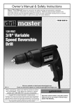
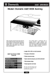
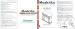
A&E AWNINGS
Model: Dometic A&E 8500 Awning
Australia’s
Favorite Awning
For great looks and long life, more
RVers choose the A&E Imperial
8500 than any other brand or
model. Its heavy-duty premium
vinyl canopy has the rich vibrant
Horizon stripe color pattern on top
and bottom with color-matched
weathershield.
The dependable, easy-operating
A&E Universal Hardware is
available in straight or curved
models to fit virtually any vehicle.
• Large torsion assembly for
dependability, long life and
smooth, effortless operation
• Patented anti-slack rafter pivot
keeps fabric tinder tension when
moving arms between pivot and
carport positions
• A&E's heaviest polyester
reinforced vinyl fabric side hems
for added durability
• Exclusive Permaloop pull strap
makes it easier to open awning
• Lengths 8ft to 25ft in
one foot increments
• Full approx. 8ft extension
A&E 8500 Colours
• 12 Months Warranty Australia wide.
• Easiest-to-use ergonomic lock knobs
BURGUNDY ROSE
• A&E Universal hardware
CODE DZ
ALPINE GREEN/PERIWINKLE
CODE DY
FAWN/CINNAMON
CODE EA
The color in this chart should be used
as a guide only. For exact fabric color,
see A&E's fabric sample kit.
GULF BLUE
CODE DX
iNDEX
RECORD THIS INFORMATION FOR FUTURE REFERENCE
BEFORE INSTALLING THE UNIT:
Model Number
Serial Number
Date Purchased
Place of Purchase
838000D, 838100D, 839000D, 840000,
8410000, 8471000, 8472000, 8474000,
8475000, 8480000, 8481000, 8481003,
8490000, 8491000,
Series
Universal Hardware
for use with
USA
The Dometic Corp.
8500, 9000
Fabric Roller Tube Assembly
.
Dometic PTY
Clayton Vic
This manual must be read and understood before installation, adjustment, service, or maintenance is performed. This unit must be installed
by a qualified service technician.
Modification of this product can be
extremely hazardous and could result in personal injury or property
damage.
Lire et comprendre ce manuel avant de
procéder à l'installation, à des réglages,
de l'entretien ou des réparations.
L'installation de cet appareil doit être
effectuée par un réparateur qualifié.
Toute modification de cet appareil peut
être extrêmement dangereuse et
entraîner des blessures ou dommages
matériels.
838000D, 838100D, 839000D,
840000, 8410000, 8471000,
8472000, 8474000, 8475000,
8480000, 8481000, 8481003,
8490000, 8491000,
SERIES
UNIVERSAL HARDWARE
INSTALLATION
INSTRUCTIONS
REVISION
Form No. 3103837.070 6/02
(Replaces 3103837.062)
(French 3108060.017)
©2002 Dometic Corporation
LaGrange, IN 46761
INDEX
1
SAFETY INSTRUCTIONS
This manual has safety information and instructions
to help users eliminate or reduce the risk of accidents and injuries.
RECOGNIZE SAFETY INFORMATION
!
This is the safety-alert symbol. When you see this
symbol in this manual, be alert to the potential for
personal injury.
Follow recommended precautions and safe operating instructions.
UNDERSTAND SIGNAL WORDS
A signal word , WARNING OR CAUTION is used
with the safety-alert symbol. They give the level of
risk for potential injury.
WARNING: means if the safety information is
not followed someone could be injured or killed
and/or damage to equipment could occur.
CAUTION: means if the safety information is
not followed someone might be injured and/or
damage to equipment might occur.
Read and follow all safety information and instructions.
Dometic
A&E 8500, 9000
INSTALLATION
COVERED BY PATENT 4,524,791; 5,351,736; 5,566,918;
5,383,346; D353,473, others pending
Application
The A&E awning with "Universal Hardware" is designed and
intended for use on motorhomes, mini-motorhomes, 5th
wheels and travel trailers with straight or curved sides. For
curved sides, please see the separate Hardware List in the
Dealer Service Manual for the appropriate model.
2. Carefully lay the fabric roller tube assembly on "V"
troughs or other well protected surface to prevent fabric
damage. Secure arm assemblies to the respective top
castings using 1/4–20 x 1/2" hex. hd. machine screws
and 1/4" lock washers. (FIG. 2)
CAUTION: DO NOT REMOVE the cotter pins at this
time and DO NOT attempt to rotate the Safe-T-LockTM
Lever until installation is complete. (Lever is pre-set
in the roll-up position.) (FIG. 2)
FIG. 4B TOP
SLAT
(9000
Awnings)
IMPORTANT: Read and understand ALL of the following steps before beginning installation.
The Dometic Corporation reserves the right to modify appearances and specifications without notice.
FIG. 3
BEFORE
Position Wheel
Directly over edge
of Door
AFTER
FIG. 1B SCREEN
ENTRY
DOOR
A door screen edge guard must be installed on the
outside of the screen door in the extreme upper corner
opposite the door hinges. (FIG. 1B)
When the entry or screen door is opened while the
awning fabric is extended low, the door roller or edgeguard (instead of the sharp door corner) contacts the
underside of the fabric.
FIG. 2
DO NOT
REMOVE
COTTER
PIN AT
THIS TIME
ARM
ASSEMBLY
DOOR
DOOR EDGE
Wheel Above
Door 1/4" – 3/8"
DO NOT ROTATE
SAFE-T-LOCK TM
LEVER
AWNING
FABRIC RAIL
AWNING
FABRIC ROLLER
RAIL
TUBE ASSEMBLY
Installation of A&E Awnings will briefly require three people.
Use the following procedure to assure a properly installed,
and properly functioning awning.
1. Where the awning is mounted above the entry door, the
door roller must be installed on the outside of the door
in the extreme upper corner above the door handle.
(FIG. 1A)
FIG. 1A
FIG. 4A
TOP
CASTING
1/4–20 X 1/2"
HEX HD.
MACH. SCREW
LOCK
WASHER
ARM
3. Prepare the awning rail to accept the awning roller
cover. Select the end from which the awning shall be
fed, then widen that end of the rail with a flat screwdriver
and file off any sharp edges. (FIG. 3)
4. With one person grasping each support arm, carefully
lift the entire assembly upright. Keep the two arm
assemblies Parallel to each other to avoid damage
due to twisting Carry the awning to the prepared
awning rail end. (FIG. 4A & B)
Feed the roller cover into the awning rail while standing
on a stepladder, (third person) while two carry the awning
assembly to the desired position.
5. Install Top Brackets
After the complete awning assembly has been threaded
into the awning rail, check to be sure that its position
allows for solid mounting of the top and bottom
brackets and that support arms are in desired location
(not restricting use of doors, access doors, egress
windows, etc.). (FIG. 5A)
AWNING OR COVER
FIG. 5A
Dometic
Place top pivot in position over awning rail from below
as shown in FIG. 5B. Align pivot directly behind and
centered with the main support arm. (Rotate the ClassA pivot onto the rail by lifting up and out on the rafter.)
Pull the main support arm away from the top bracket and
rafter. Mark the top bracket position and predrill the two
holes (use a 3/16" drill bit in steel.) Install top bracket
over the awning rail. Apply sealant to the threads of the
two #14x2-1/2" hex. hd. screws and where the screws
enter the coach with clear silicone. Secure the top
bracket. Place main support arm on the top pivot.(FIG.
5B).
FIG. 5B
6. Install Bottom Brackets
Snap the patio foot on the bottom of the inner arm into the
bottom bracket. (FIGS. 6A & 6B). Insure the arm top
casting is resting on the top pivot. Lift the main arm
handle and slide the inner arm up to the desired mounting
position. Select the best supporting structure, i.e. mount
directly into the floorline, molding, etc.
Release the handle and slide the inner arm down until the
handle lock button snaps into a hole. Close the travel
latch.
Mark position of bottom bracket holes into the floorline.
Pre-drill two 3/16" dia. holes through the marked loca
tions. (Drill 7/32" dia. into steel).
TOP BRACKET
Disconnect bottom bracket from patio foot and secure it
to the coach using two #14 x 2" hex head screws. Apply
sealant to the threads of the two #14x2-1/2" hex. hd.
screws and where the screws enter the coach with clear
silicone. (FIG. 6C). Snap the foot back into the bracket.
#14 x 2 1/2"
Hex Hd. Screw
Universal Hardware
Mounting
AWNING RAIL
RAFTER
TOP
PIVOT
Repeat for other side.
FIG. 6C
APPLY SEALANT
After the top bracket has been mounted, do not pull the
bottom of the arm assembly away from the side of the
vehicle, with the Safe-T-LockTM in the roll-up position.
Damage to the torsion lock can occur, which may cause
the torsion to malfunction.
APPLY
TO SEALANT
SCREWTO
SCREW
HEADS
THREADS
BOTTOM MOUNTING
BOTTOM
BRACKET
BRACKET
#14 x 2"
Lift the arm handle (releasing lock button) and CAREFULLY extend the inner arm to the ground to support the
awning. (FIG. 6B).
HEX.
HD. SCREWS
#14 X 2
INCH
HEX HD
REW
NOTE: If installing over a molding, A&E Standoff Kit
3104781 must be used (See Fig. 6D).
Repeat for the other side.
FIG. 6B
RRELEASE
EVEL ESLEVER
AELER
FIG. 6D
BOTTOM
FIG. 6A
PATIO
OFOOT
ITAP
TOOF
M
OT TOB
BRACKET
GNITNUOM
TEKCARB
STANDOFF
MOLDING
7. Install Stop Plugs.
This step is essential for the proper
functioning of all A&E Awnings.
Using the lift handle, RAISE THE MAIN ARM UP BY ONE
HOLE ONLY.
9. Secure Awning to Awning Rail
Open and close awning a few times to allow for natural self
adjustment of awning.
Secure by installing a #6 x 1/2" Tek screw into the rail.
(FIG. 9A & 9B) Repeat at other end.
FIG. 9A
2"
AWNING RAIL
Install an aluminum stop washer on the inner arm face,
through the hole closest to the bottom of the main arm
with a #10 x 5/8" phillips screw and a #10 lock nut (FIG.
7).
#6 x 1/2" TEK SCREW
TOP
BRACKET
FIG. 7
FABRIC
MAIN ARM
#10 LOCK NUT
AWNING RAIL
ALUMINUM
STOP WASHER
FIG. 9B
#6 x 1/2" TEK SCREW
3/16" DIA. HOLE
CLOSEST TO
#10 x 5/8"
PHILLIPS HD.
INNER
THE MAIN SUPPORT ARM SHOULD NOW CLEAR
THE TOP PIVOT WHEN THE AWNING CLOSES.
Repeat for other side.
8. Release Pre-Set Tension.
Move the Safe-T-LockTM lever to the roll down position.
Remove cotter pin that is holding factory pre-set torsion.
The cotter pin is found in the roller tube end cap (FIG. 8).
For easier removal, twist the roller tube as if unrolling
awning while pulling on cotter pin.
FIG. 8
COTTER
PIN
SAFE-T-LOCK TM
LOCK DIRECTION
LEVER
END CAP
TOP
BRACKET
10.Operate awning according to the Operating Instructions
to check that all parts function properly.
11.Secure Awning for Travel.
For added security and rattle-free travel, tighten rafter
knobs, secure travel latches and insure torsion lock is in
the roll up position. (FIGS. 8, 10A & 10B).
FIG. 10A
MAIN ARM
OPEN TRAVEL-LATCH
When cotter pins are removed, springs are under
tension. The awning will attempt to close. Keep
body clear of hardware and roller tube.
Discard pin and repeat for other side.
MAIN ARM
FIG. 10B
CLOSED TRAVEL LATCH
TO OPEN AWNING:
Back to index
1
2
Loosen the black adjustment knob behind each main arm.
• Sunchaser Awnings: push travel latch tab toward center of
arm to disengage.
• 8500/9000/ Awnings: Flip travel
lock latches up.
Using the provided pull rod,
reach up and pull the locking lever forward to release
the awning.
4
Slide one rafter arm up until it snaps into
place. Pull down and out on the sliding
rafter to remove slack from the fabric,
and tighten the black adjustment knob.
Repeat for other side.
6
Pull up on the lift handle and raise the
arm assembly to the desired height.
Swing handle in and allow the lock
button to snap into one of the holes.
Repeat for other side.
TO CLOSE AWNING:
1
3
Hook the rod into the loop of the pull
strap, and pull the awning all the way
out.
Pull stakes from the ground, lower arm to the shortest position,
swing arm toward the vehicle, and snap the patio foot into the
bracket. Repeat for other side and proceed to next step.
2
Raise the lift handle to
release the lock button.
Lower main arm to the
stop plug. Swing the
handle in to engage the
lock button in a hole.
Repeat for other side.
5
7
Lower arm to shortest position. Press the
release lever at the bottom end of main arm,
pull the arm assembly outward to a vertical position and adjust height. Repeat for
other side. Drive stakes through holes of
each patio foot into the ground. Stake kits
are available from your awning retailer.
Slide the pull strap to the
right end of the roller, and
wrap it around the main arm.
8
During rain, lower the end furthest from the door
to allow water to flow off.
Whenever heavy or prolonged rain or wind is
anticipated, or you will leave the awning unattended, it is best to close the awning. Damage as
a result of weather is not covered by warranty.
3
A: Loosen black adjustment knob. B: Lift slider catch. C: Slide
the rafter arm down to the bottom of the main arm. Leave black
adjustment knob loose. Repeat for other side.
TO OPEN AWNING:
TO CLOSE AWNING:
1
2
Loosen the black adjustment knob behind each main arm.
• Sunchaser Awnings: push travel latch tab toward center of
arm to disengage.
• 8500/9000/ Awnings: Flip travel
lock latches up.
Using the provided pull rod,
reach up and pull the locking lever forward to release
the awning.
4
Slide one rafter arm up until it snaps into
place. Pull down and out on the sliding
rafter to remove slack from the fabric,
and tighten the black adjustment knob.
Repeat for other side.
6
Pull up on the lift handle and raise the
arm assembly to the desired height.
Swing handle in and allow the lock
button to snap into one of the holes.
Repeat for other side.
1
3
Hook the rod into the loop of the pull
strap, and pull the awning all the way
out.
Pull stakes from the ground, lower arm to the shortest position,
swing arm toward the vehicle, and snap the patio foot into the
bracket. Repeat for other side and proceed to next step.
2
Raise the lift handle to
release the lock button.
Lower main arm to the
stop plug. Swing the
handle in to engage the
lock button in a hole.
Repeat for other side.
5
7
Lower arm to shortest position. Press the
release lever at the bottom end of main arm,
pull the arm assembly outward to a vertical position and adjust height. Repeat for
other side. Drive stakes through holes of
each patio foot into the ground. Stake kits
are available from your awning retailer.
Slide the pull strap to the
right end of the roller, and
wrap it around the main arm.
8
During rain, lower the end furthest from the door
to allow water to flow off.
Whenever heavy or prolonged rain or wind is
anticipated, or you will leave the awning unattended, it is best to close the awning. Damage as
a result of weather is not covered by warranty.
3
A: Loosen black adjustment knob. B: Lift slider catch. C: Slide
the rafter arm down to the bottom of the main arm. Leave black
adjustment knob loose. Repeat for other side.
HELPFUL HINTS FOR AWNING CARE
TO CLOSE AWNING (Continued):
4
5
•
Whenever the awning is wet while rolled up, as soon as conditions allow, roll it
•
out and let it dry before rolling it up again. This will help prevent mildew and
rotting.
Mildew does not form on the fabric itself, but on the accumulated dust, dirt and
•
grime. Periodically clean vinyl or woven acrylic. Refer to cleaning instructions
below for fabric care.
Always make sure the awning is extended high enough before opening the entry
•
door.
Apply silicone spray lubricant as needed to keep the awning’s moving parts
A&E SUNCHASER • 8500 • 9000
Patio Awnings
operating smoothly. For ease of operation on hardware, rub candle wax on all
sliding surfaces.
Grasp the pull strap, pull toward you, and flip the locking lever up to the ROLL UP
position.
Do not release the awning
pull strap now. It is under tension and could snap back
against the vehicle side.
Slide the pull strap to the center, and using it to control
speed, allow the awning to
return to the vehicle side.
Note: Allow the strap to wind
diagonally to prevent a bulge
in the fabric.
6
Tighten black adjustment knob.
• Sunchaser Awnings: Squeeze rafter into arms to engage latch.
• 8500 & 9000: Flip travel lock latch down.
Repeat other side. Your awning is now ready for travel.
A&E ACCESSORIES FOR COMFORT AND CONVENIENCE:
• A&E Slide Topper™ protects your slideout unit.
• A&E Patty O’Mat™ under your awning looks great and keeps
dirt from being tracked into your RV.
• A&E Window Awnings keep your RV cooler and protect your
furnishings from sun damage.
Ask your RV dealer to show you these quality accessories and more
from A&E.
A&E 8500 and SUNCHASER:
•
Abrasion, weather and long hours in the sun are vinyl’s worst enemies. To avoid
these problems, you will need to keep your awning clean. Use a mixture of 1/4
cup dish soap, 1/4 cup bleach and five gallons of fresh water. Soap the open
awning with this mixture, then roll it up and let stand for five minutes. Rolling
up of the awning will apply the mixture to the underside of the fabric. Unroll the
awning and hose off the top and bottom with clean water. Repeat if necessary
and allow to completely dry.
A&E 9000 :
•
In addition to its beauty and soft translucence, woven acrylic fabric offers the
advantages of strength and breathability. It is water repellent; but because it is
a woven cloth, it is not water proof. To keep your acrylic awning clean, simply
hose it off occasionally and let it dry. Do Not Scrub.
•
Avoid touching the underside of the 9000 canopy when it is wet. To do so will
break the surface tension of the water and encourage seepage through the fabric.
•
Because woven acrylic is of a much lighter weight than vinyl, shifting may occur
if the awning and pull strap are not centrally aligned with the fabric roller tube
while the awning is being rolled up. If necessary, roll the awning out and adjust
the alignment.
WHEN TO GET MORE HELP:
•
If malfunctions occur that cannot be corrected by reviewing this user’s guide,
contact a qualified Dometic service technician.
Note: A slight “travel line” may appear where the door roller contacts the awning fabric. This is considered normal and does not affect
the integrity of the awning.
REVISION
Form No. 3108608.013 5/01
(Replaces 3108608.005)
(French 3109197.016)
User’s Guide
by The Dometic Corporation
A&E AWNINGS - SPARE PARTS
Model: Dometic A&E 8500/9000 Awning
128
A&E AWNINGS - SPARE PARTS
Model: Dometic A&E 8500/9000 Awning
SATIN HARDWARE
ITEM DESCRIPTION
No.
1
Arm, main (A1-A6) (2 req.)
A1 Handle. lift (G1-G2)
A2 Pop Rivet (4 req.)
A5 Safety lock
A6 Catch, slider (pair)
TALL
SHORT
8482003.001
3104502.293S
830644
308171.020
830587.001
830472.002
8483003.002
3104502.301S
830644
308171.020
830587.001
830472.002
2
Rafter, main (B1 -B3) (2 req.)
B1 Bracket asm.
B2 Bumper, rubber
B3 Rivet. semi-tube
830295.536S
830333
141031
143002.053
830295.537S
830333
141031
143002.053
3
Rafter, secondary (C1-C2) (2 req.)
C*. SIider asm.
C2 Rivet. semi tube
Arm asm adj. (D1-D2) (2 req.)
D1 Foot
E1 Rivet. semi tube
D2 Rivet. semi tube
830463.511S
830463
143002.055
830466.516S
3108708.342
143002.059
143002.058
830463.512S
830463
143002.055
830466.516S
3108708.342
143002.059
143002.058
Nut special (2 req.)
Knob (2 req.)
EZ pull rod
Stake. tent (4 req.)
Kit hardware
STD
Kit hardware screw, includes
Washer (2 req.)
Screw (2 req.)
Screw (2 req.)
Screw (2 req.)
Nut lock (2 req.)
Washer, stop (2 req.)
Screw (4 req.)
Screw (4 req.)
3104652.007
3105421.014
830152.102
3104257.005
3104125.020
3104852.003
3104652.007
3105421.014
830152.102
3104257.005
3104125.020
3104852.003
4
5
6
7
9
10
129
A&E AWNINGS - SPARE PARTS
Model: Dometic A&E 8500/9000 Awning
130
A&E AWNINGS - SPARE PARTS
Model: Dometic A&E 8500/9000 Awning
WHITE HARDWARE
ITEM
No.
DESCRIPTION
TALL
SHORT
8483003.401B
8483003.402B
1
Arm, main (A1-A6)(2 req.)
A1 Handle, lift (G1-G2)
A2 Pop Rivet (4 req.)
A5 Safety lock
A6 Catch, slider
3104502.293B
830644
308171.020
830587.001
830472.002
3104502.301B
830644
308171.020
830587.001
830472.0O2
2
Rafter, main (B1-B3) (2 req.)
B1 Bracket asm.
B2 Bumper, rubber
B3 Rivet. semi-tube
830295.536B
830333
141031
143002.053
830295.537B
830333
141031
143002.053
3
Rafter, secondary (Cl -C2) (2 red.) 830463.511B
C1 Slider asm.
830463
C2 Rivet, semi tube
143002.055
830463.512B
830463
143002.055
4
Arm asm., adj. (D1-D2) (2 req.)
D1 Fact
E1 Rivet, semi tube
D2 Rivet. semi tube
830466.516B
3108708.342
143002.059
143002.058
830466.516B
3108708.342
143002.059
143002.058
5
6
7
9
Nut. special (2 req.)
Knob (2 req.)
EZ pull rod
Stake, tent (4 req.)
3104652.007
3105421.014
830152.102
3104257.005
3104652.007
3105421.014
830152.102
3104257.005
10
Kit hardware
STD
3104125.020
Kit hardware. screw, includes 3104852.003
Washer (2 req.)
Screw (2 req.)
Nut lock (2 req.)
Washer, stop (2 req.)
Screw (4 req.)
Screw (4 req.)
3104125.020
3104852.003
131
A&E AWNINGS - SPARE PARTS
Model: Dometic A&E 8500/9000 Torsion Assemblies
Part No.: 3108399.035 TORSION ASSEMBLY – RIGHT-HAND
Part No.: 3108399.019 TORSION ASSEMBLY – LEFT-HAND
132
A&E AWNINGS - SPARE PARTS
Model: Dometic A&E 8500/9000 Torsion Assemblies
ITEM
No.
PART
No.
DESCRIPTION
A4
A5
A6
A7
A8
730013.001
730297.001
3104384.031
830567.005
3104384.023
Spring, torsion
Rod, torsion
Pin, drive 1/8 (2 req.)
Top casting, painted w/Warning Label
Pin, drive 5/32
B1
B2
B4
B5
B6
830496.012
730013.002
3104384.031
830567.005
3104384.023
End cap asm., painted
Spring, torsion
Pin, drive lock 1/8"
Top casting, painted w / Warning Label
Pin, drive lock 5/32
133
A&E AWNINGS - SPARE PARTS
Model: Dometic A&E 8500/9000 Awning
ITEM PART
No.
No.
DESCRIPTION
1
2
3
6
Torsion Asm, RH
Torsion Asm, LH
Pull Strap
Roller tube
8'
Roller tube
9’
Roller tube
10’
Roller tube
11'
Roller tube
12'
Roller tube
13'
Roller tube
14'
Roller tube
15'
Roller tube
16'
Roller tube
17'
Roller tube
18'
Roller tube
19’
Roller tube
20'
Roller tube
21'
Roller tube
22'
Roller tube
23'
Roller tube
24'
Roller tube
25'
3108399.001
3108399.019
940001
3108340.008
3108340.009
3108340.010
3108340.011
3108340.012
3108340.013
3108340.014
3108340.015
3108340.016
3108340.017
3108340.018
3108340.019
3108340.020
3108340.021
3108340.022
3108340.023
3108340.024
3108340.025
Colour Code:
7.
Fabric Assembly
R3108049(Colour
R3108049(Colour
R3108049(Colour
R3108049(Colour
R3108049(Colour
R3108049(Colour
R3108049(Colour
R3108049(Colour
R3108049(Colour
R3108049(Colour
R3108049(Colour
R3108049(Colour
R3108049(Colour
R3108049(Colour
R3108049(Colour
R3108049(Colour
R3108049(Colour
R3108049(Colour
Code).508
Code).509
Code).510
Code).511
Code).512
Code).513
Code).514
Code).515
Code).516
Code).517
Code).518
Code).519
Code).520
Code).521
Code).522
Code).523
Code).524
Code).525
8'
9'
10'
11'
12'
13'
14'
15'
16'
17'
18'
19'
20'
21'
22'
23'
24'
25'
SEE INDEX FOR CORRECT COLOUR CODES
DZ
DX
EA
EH
134
=
=
=
=
Burgundy Rose
Gulf Blue
Cinnamon/Fawn
Pewter
8300 8500 9000 REPLACEMENT OF TORSION ASSEMBLY
1. Insert the leg of the idler opposite the torsion spring screw
and washer over the seamed groove of the roller tube. See
FIG. 10.
NOTE: The idler leg opposite the torsion spring screw
has a triangle shape.
FIG. 10
2. Installation of a new roller tube may require a notch cut in
the side of the groove away from lock lever for each poly
rope. See FIG. 11.
NOTE: Insert torsion idler into roller tube before the poly rope
is stretched. See Section E. Step 1.
3. Use pliers to stretch the poly rope 1/4" – 1/2" and tuck it
into the notch and place off to the side. See FIG. 13A13G. Repeat Steps 1 and 2 on opposite end.
FIG. 11
FIG. 12
FT
LE
RIG
H
T
WIND TO
ADD TORSION
CAP A
ROLL
UP
ROLL
DN
FT
LE
RIG
H
T
WIND TO
ADD TORSION
CAP B
ROLL
UP
The left-hand end cap is always positioned with the open
notch over the open groove. See FIG. 13G.
5. Mark the location of rivet holes in the end cap on roller
tube. Drill 3/16" hole. Remove any drill burrs from inside
roller tube.
CAP C
6. Attach end cap to roller tube with two 3/16" x 3/8" pop
rivets. Repeat on opposite end.
5
ROLL
DN
4. Slide torsion assembly into roller tube. Identify the end
cap "A", "B" or "C" (refer to FIG. 12). Position the SafetyT-Lock™ Lever as shown in FIGS. 13A–13F.
FIG. 13A
RIGHT-HAND
END CAP “A”
Fabric without
hemmed edge
Cut Poly Rope flush
with end of tube
See Fig. 11
ROLL
UP
Open
Groove
ROLL
DN
WIND TO
ADD TORSION
FT
LE
RIG
HT
Place open notch
in alignment with
open groove
Valance
Trim Poly Rope
leaving sufficient
length to tuck in
place behind the
open groove
RIGHT-HAND
END CAP “A’
Fabric edge
folded and
hemmed
Place open notch in alignment
with fabric groove
Cut Poly Rope flush
with end of tube
FIG. 13B
LEF
See Fig. 11
T
RIGHT
TO N
D SIO
IN
W TOR
D
AD
LL
RO
UP
Open
Groove
LL
RO D N
Valance
Trim Poly Rope
leaving sufficient
length to tuck in
place behind the
open groove
RIGHT-HAND
END CAP “B”
Place open notch in alignment
with fabric groove
Fabric edge
folded and
hemmed
Cut Poly Rope flush
with end of tube
HT
See Fig. 11
W
ADD IND TO
TOR
SIO
N
ROL
L
DN
LEFT
RI
G
FIG. 13C
ROL
UP L
Open
Groove
Valance
6
Trim Poly Rope
leaving sufficient
length to tuck in
place behind the
open groove
RIGHT-HAND
END CAP “B”
Fabric without
hemmed edge
Cut Poly Rope flush
with end of tube
ROLL
DN
See Fig. 11
ROLL
UP
FIG. 13D
Trim Poly Rope
leaving sufficient
length to tuck in
place behind the
open groove
Open
Groove
WIND TO
ADD TORSION
FT
LE
RIG
HT
Place open notch
in alignment with
valance groove
Valance
RIGHT-HAND
END CAP “C”
Place open notch in alignment
with fabric groove
Cut Poly Rope flush
with end of tube
Fabric without
hemmed edge
FIG. 13E
See Fig. 11
Trim Poly Rope
leaving sufficient
length to tuck in
place behind the
open groove
Open
Groove
Valance
RIGHT-HAND
END CAP “C”
Cut Poly Rope flush
with end of tube
Fabric edge
folded and
hemmed
FIG. 13F
See Fig. 11
Open
Groove
Place open notch
in alignment with
Open groove
Valance
7
Trim Poly Rope
leaving sufficient
length to tuck in
place behind the
open groove
FIG. 13G
LEFT-HAND END CAP
Fabric
Trim Poly Rope
leaving sufficient
length to tuck in
place behind groove
The Left-Hand
End Cap is always
placed with open
notch in alignment
with open groove
See
Fig. 11
Valance
Open Groove
F. WINDING TORSIONS
AWNING LENGTH
1. Insert torsion winding tool into torsion rod. See FIG. 7.
8'
9'
10'
11'
12'
13'
14'
15'
16'
17'
18'
19'
20'
21' AND ABOVE
2. Always have the speed wrench handle at the 6 O-clock
positions and turn towards the side of the coach. Left
hand end cap is turned clock-wise and right hand end cap
is turned counter-clock-wise to add tension.
FIG. 14
*
ROLLED UP
TURNS *
EXTENDED
TURNS*
5
5
5
5
5
6
6
7
7
9
9
10
10
10
11
11
11
11
11
12
12
13
13
15
15
16
16
16
Add 6 additional turns to torsion spring when
awning is fully extended.
3. After torsion spring is wound to proper number of turns,
insert a steel pin in the end cap to prevent rapid spin-off
when reinstalling on coach. See FIG. 3, Page 2.
NOTE: Right hand torsion must have Safe-T-Lock™
lever in the roll-down position.
4. Reinstall awning per the Operating and Installation Manual.
If the awning is not removed from the coach, reverse
disassembly procedure.
8
A&E
Patio Awnings
DIAGNOSTIC SERVICE MANUAL
This program will address the most common system problems associated with the A&E Patio Awnings supplied by
The Dometic Corporation. Our intent is to provide you with a guideline of checks to make, should you encounter one
of the following symptoms.
SYMPTOM
CAUSE
REFER TO
1.
Black adjustment knob will not tighten
Nutsert
Washer Stack-up
1.1
1.2
2.
Fabric leaks at the roller tube
Stitches
2.10
3.
Main support arms will not extend
Push button assembly
Adjustable arm assembly
1.3
1.4
4.
Awning has bulges or wrinkles where pull strap
rolls up
Operation
3.1
5.
Awning fabric will not roll up straight
Fabric position
Out of square
2.1
2.2
6.
Weatherguard wrinkled
Seams
Vehicle sidewall
Tek screws
Weatherguard
Out of square
2.4
4.2
2.12
2.3
2.2
7.
Fabric does not hang well
Out of square
Tube deflection
Tek screws
Seams
Vehicle sidewall
Stitches
2.2
2.6
2.12
2.4
4.2
2.10
8.
Must lift main arm(s) to open or close the awning
Stop plug
Bottom mounting brackets
1.7
1.6
9.
Awning arm(s) stay up against side of coach when
trying to open awning
Top mounting bracket
Fabric position
Operation
Travel lock
1.5
2.1
3.1
3.4
10. Awning will not roll up
Rafters
Cam
Black adjustment knob
Torsions
1.8
2.9
1.9
2.8
11. Awning will not stay in rolled down position
Cam
2.9
12. Awning billows out when traveling down the road
Cam
2.9
13. Awning stops at guard when rolling up
Rafters
Stop plug
Operation
Torsions
Awning rail
Top mounting brackets
1.8
1.7
3.2
2.8
4.3
1.5
1
Diagnostic Service Manuals
A&E
Patio Awnings
SYMPTOM
DIAGNOSTIC SERVICE MANUAL
CAUSE
REFER TO
14. Water leaks through guard
Operation
Guard
Tube deflection
3.3
2.5
2.6
15. Water drips down the side of coach
Awning rail
Rubber seal
4.1
2.7
16. Water leaks through fabric
Fabric
2.11
SECTION 1
1.2 WASHER STACK-UP
HARD
WARE COMPONENTS
HARDW
Washer stack-up merely means the proper positioning of
the washers on the stud of the black adjustment knob.
Remove the knob and check for proper washer position.
The plastic washer should be against the main rafter,
and backed by the metal washer for stiffness. If the
stack-up is not proper it should be corrected.
1.1 NUTSERT OR SPECIAL NUT
The nutsert is simply a threaded fastening device
used to tighten down the black adjustment knob. If
the knob will not tighten, first
remove the secondary rafter
assembly from the hardware.
Turn the knob to determine if
the nutsert is stripped or
NUTSERT
spinning. If so, replace the
nutsert. If you cannot turn the
knob it will be necessary to
replace both the nutsert and
the black adjustment knob.
On some arm assemblies the
nutsert has been replaced with
a SPECIAL NUT
NUT. If the knob will
not tighten, first separate the rafter assembly. Turn
the knob to determine if the special nut is stripped. If
so, replace the special nut. If you cannot turn the
knob, it will be necessary to replace both the special
nut and the back adjustment knob.
SPECIAL
NUT
SECONDARY
RAFTER
PLASTIC WASHER
METAL WASHER
ADJUSTMENT KNOB
1.3 PUSH BUTTON ASSEMBLY
The push button assembly locks the main support arm to
the adjustable arm assembly and controls the height of
the awning in the open position. To check it, open the
awning to full extension. Look inside the main support
arm, and activate the push button to see if the locking pin
is moving in and out of the hole in the adjustable arm
assembly. If the locking pin does not move, or has been
SD 66 BS RIVET
(3/16 DIA. POP
RIVET)
COMPRESSION
SPRING
LIFT HANDLE LOCK BUTTON
3/16" X 1/4"
GRIP
ALUMINUM
POP RIVET
BUTTON
LOCK
BUTTON
RETAINER
MAIN SUPPORT
ARM
NOTE
NOTE: The special nut could be a large hex nut as
well as the one shown.
2
SD 66 BS RIVET
(3/16 DIA. POP RIVET)
#8—32
HEX NUT
A&E
Patio Awnings
DIAGNOSTIC SERVICE MANUAL
broken off, the push button assembly must be replaced.
At times the lock pin of the push button assembly can
break off and jam between the push button housing and
the adjustable arm assembly, making it difficult to extend
the main support arm.
1.4 ADJUSTABLE ARM ASSEMBLY
The adjustable arm assembly allows for telescoping
height adjustment of the main support arm, and it
connects to the bottom mounting bracket to support the
weight of the awning. If the main support arm cannot be
extended freely, the adjustable arm assembly should be
checked. Remove the adjustable arm assembly and
check for nicks, burrs, bends or twists. If any deflection
is noted, the adjustable arm assembly must be replaced.
For ease of operation apply GO-EASY, a special lubricant.
LIFT
HANDLE
ARM
ASSEMBLY
ADJUSTABLE
ARM
NOTE: GO-EASY is available from your distributor.
1.5 TOP MOUNTING BRACKETS
The top mounting bracket supports the main rafter
assembly to hold the awning in the open extended
position, and allows the rafter to pivot into the “C”
channel of the main support arm. Each top mounting
bracket should be mounted directly over the awning rail
so the screws go through the “C” portion of the rail.
TOP MOUNTING BRACKET
On the Series 9000 awning the top mounting bracket
can be mounted lower when possible. If the top mounting bracket is mounted above center of the awning rail,
the aluminum guard may not cover the fabric completely
in the closed position. If this is the case, relocate the
top mounting bracket accordingly.
The top mounting brackets have slotted holes for the
mounting screws, allowing them to be adjusted side to
side. To adjust the brackets, close the awning and
sight down the main support arm and the main rafter.
The clearance on each side of the rafter should be
approximately 1/4 inch. If clearance is not appropriate,
adjust the top mounting bracket(s) as necessary.
1.6 BOTTOM MOUNTING BRACKETS
The bottom mounting brackets
are screwed to the
floor line of the
unit, and they
support the
weight of the
BOTTOM MTG.
BRACKET
awning. They
INSERT
also provide a
BOTTOM
BOTTOM
MOUNTING
quick release
MOUNTING
BRACKET
BRACKET
to set up the
SPACER
#14 X 2-1/2"
HEX. HD. SCREWS
awning in
the patio
position. If a bottom mounting
bracket settles, sags, or becomes loose it can reduce
the clearance between the top casting of the torsion
and the extension of the top mounting bracket, making
operation difficult.
Check the bottom mounting bracket for looseness or
settling, and tighten or reposition it accordingly for
proper operation.
1.7 STOP PLUG
The stop plug is a mechanical stop that supports the
main arm when opening and closing the awning. It
controls the clearance between the top casting of the
torsion to the extension of the top mounting bracket.
This clearance should be 1/4 inch to 1 inch. To adjust
the clearance, raise or lower the stop plug as needed.
On the 9000 and 9500 Series awning the clearance
should be kept to a minimum for best operation.
TOP VIEW OF MAIN SUPPORT
ARM AND RAFTER
MAIN SUPPORT ARM
RAFTER
1/4" CLEARANCE, EACH SIDE
FROM TOP TO BOTTOM OF
ARM ASSEMBLY
3
A&E
Patio Awnings
DIAGNOSTIC SERVICE MANUAL
Attempting to open the awning without first loosening
the black adjustment knobs can damage the slider of
the secondary rafter, making it difficult to open the
awning.
TOP MOUNTING
BRACKET
AWNING RAIL
SECTION 2
FABRIC R
OLLER TUBE ASSEMBL
Y (FR
TA)
ROLLER
ASSEMBLY
(FRT
CLEARANCE
EXTENSION
2.1 POSITION
For the awning to operate properly the fabric must be
positioned properly in the awning rail and on the roller
tube.
Open the awning and check the position of the fabric
between the top mounting brackets. If the fabric is not
centered, remove the tek screws, center it, and replace
the screws.
MAIN SUPPORT ARM
STOP PLUG
MAIN ARM
STOP
PLUGS
#10 LOCK NUT
3/16" DIA. HOLE
CLOSEST TO
MAIN ARM
CLEARANCE
FROM FABRIC
TO END CAP
#6 X 1/2" TEK SCREW
2"
1.8 RAFTERS
The rafters telescope from the top mounting brackets to
the main support arms to provide tension on the fabric
in the full open position. If the rafters are bent or
twisted, this will hinder the operation of the awning.
Open the awning and remove the secondary
rafter from the main support arm. Now
sight down the main and secondary
rafters and check for any
bends, twists or deflection. If
one or the other rafter is
not true it should be
MAIN RAFTER
replaced.
SECONDARY RAFTER
SLIDER
1.9 BLACK ADJUSTMENT KNOB
The black adjustment knob tightens the secondary
rafter to the main rafter to keep the fabric taut in the full
open position.
When closing the awning, the knob should not be
tightened down until after the awning is rolled up and
the travel lock is engaged.
4
AWNING RAIL
TOP
BRACKET
VINYL FABRIC
When the fabric is properly positioned, next check the
position of the fabric on the roller tube. The clearance
from the end cap of the torsion assembly to the edge of
the fabric must be the same on each end. If it is not,
adjust the fabric on the tube as necessary.
On the Elite 9000 and 9500 awning the fabric is held in
place to the weatherguard with 1/8" pop rivets. Check
the position of the fabric at each end of the weatherguard.. If the fabric has shifted, remove the pop rivets,
center the fabric and re-rivet.
2.2 SQUARE
If the fabric on the awning is out of square, it could
cause the fabric to telescope in one direction when
rolling up, or to not hang properly in the open position.
A&E
Patio Awnings
DIAGNOSTIC SERVICE MANUAL
To check fabric for square, measure from the top right
hand corner of the fabric (not the weatherguard) to the
bottom left hand corner at the poly rope. Now measure
from the top left hand corner to the bottom right hand
corner as shown below.
AWNING
RAIL
WEATHER
GUARD
FABRIC
1ST POLY
ROPE
ROLLER
TUBE
DISTANCE FROM FABRIC TO END CAP (SAME ON EACH END)
In this check, the difference of the two dimensions
should be no more than one inch. If it is more, the
fabric is out of square, and replacement would be
necessary.
The seams of the vinyl awning are electronically welded
together with a heat seal. The welded seams are the
strongest part of the fabric. If the fabric has wrinkles or
sags, it may be due to improper seam welding. A close
inspection may reveal the seams to be the source of the
problem. If so, fabric replacement would be needed.
Whenever wrinkles are detected in the fabric, stretching of
the weatherguard should be performed before the fabric is
condemned for bad seams. See 2.3 for stretching
instructions.
2.5 ALUMINUM GUARD
The aluminum guard on the Elite 9000 and 9500 is the
last 15 inches of the awning that encloses it in the rolled
up position, and protects the woven acrylic fiber fabric
from the environment and elements.
On 9000 awnings that have the hinge slat which fits
into the awning rail:
When the awning is fully extended, the aluminum guard
should have an arch of at least 2 inches. The arch helps
water to run off rather than between the sections of the
guard.
NOTE
NOTE: The aluminum guard is not waterproof.
2.3 WEATHERGUARD
The weatherguard is the
last 15 inches of the
awning that encloses
the fabric in the rolled
up position. It protects
the striped fabric from
the environment and
elements. The weatherguard is a heavy 17
oz. vinyl fabric.
#6 X 1/2" TEK SCREW
SECOND SLAT
2" MIN.
2"
TOP SLAT/HINGE ASSEMBLY
BOTTOM SLAT
ELITE 9000 SHIELD ASSEMBLY
AWNING RAIL
TOP
BRACKET
VINYL FABRIC
When the vinyl weatherguard or fabric has
excessive wrinkles, it will be necessary to stretch the
weatherguard or fabric. Open the awning and allow the
fabric to warm up. Remove one Tek screw, grasp the
weatherguard, stretch it, and resecure the screw. Repeat
this procedure for the other end, making sure to stretch
each side an equal distance, keeping the fabric centered
between the top mounting brackets.
Close and reopen the awning three times. If wrinkles are
still present, repeat the above stretching procedure. This
may have to be done 4 or 5 times before all wrinkles
disappear.
To check the aluminum guard for proper arch, open the
awning to full extension, making sure the fabric is taut.
Hold a flat edge to the bottom of the guard and measure
from the flat edge to the inside of the arch at its highest
point. If the measurement is less than 2 inches, the guard
should be replaced.
On both 9000 and 9500 awnings that DO NOT have the
hinge slat
slat:
The arch of the aluminum guard is not important as the
fabric goes under the aluminum guard and attaches the
awning to the awning rail.
2.6 ROLLER TUBE
2.4 SEAMS
5
A&E
Patio Awnings
DIAGNOSTIC SERVICE MANUAL
9000 WITH HINGE SLA
T
SLAT
E
C
D
D
D
A - VINYL STRIP
B - HINGE SLA
T
SLAT
C - TOP SLA
T
SLAT
D - MAIN SLA
T
SLAT
E-A
WNING RAIL
AWNING
VINYL STRIP "A"
D
D
INSTALL A 1/8"
POP RIVET
EACH END
HINGE SLAT "B"
TOP SLAT "C"
VIEW RH END
E
5/16" CHANNEL
BOTH ENDS
C
MAIN SLAT "D"
VIEW RH END
D
D
D
5/16" CHANNEL
INSTALL TOWARD
CANOPY
1/4" CHANNEL
INSTALL TOWARD
AWNING RAIL
D
3/8" CHANNEL
FOR VINYL
STRIP "A"
HINGE SLAT "B"
D
1/4" CHANNEL
INSTALL A 1/8"
POP RIVET
EACH END
9000 AND 9500 WITHOUT HINGE SLA
T
SLAT
6
VINYL STRIP "A"
5/16" ROD IN
AWNING RAIL
A&E
Patio Awnings
DIAGNOSTIC SERVICE MANUAL
The roller tube is a 3-1/2 inch diameter tube. It has three
symmetrical grooves to retain the poly ropes of the awning
fabric.
If the fabric appears to have more than normal sag, the
roller tube deflection must be taken into consideration.
Depending on the length of the awning, the roller tube can
deflect from one to five inches with the awning in the open
position.
Installing a tension rafter will usually remove 80 per cent of
sag and roller tube deflection. All awnings 22 feet and
longer should be installed with heavy duty hardware which
includes a center tension rafter, a center supporter, and
heavy duty adjustable arm assemblies.
If the roller tube is bent, it will bounce up and down when
opening and closing the awning. On the 9000 Series this
can cause the aluminum guard to leak, because the guard
assembly may not be tight.
provides tension on the roller tube to roll the awning up
into the travel position.
The right hand torsion end cap contains a cam assembly which prevents the awning from billowing or unrolling during travel. It also allows one-person set-up of
the awning by preventing rollback.
When difficulties are experienced in rolling the awning
up, the tension on the torsion should be checked. In
#6 MACHINE SCREW
TOP CASTING
WASHER
END CAP
WITH ASSY.
3/16" POP RIVETS
2.7 RUBBER SEAL
On the 9000 Series awning(see Section 2.5), an extruded black rubber seal is located at the awning rail of
the coach. The seal slides into the metal hinge which
connects the aluminum guard to the awning rail. This
seal is designed to prevent water from running down the
side of the coach.
To check, inspect the full length of the seal for proper
positioning, and for cuts, tears or wrinkles. If any of
these problems are found, the seal should be repaired or
replaced.
On some units it may be necessary to silicone seal the
lips of the rubber seal to the awning rail and the top slat
of the aluminum guard as shown , to prevent water from
running down the side of the RV.
TORSION SPRING/
STABILIZER ASSEMBLY
IDLER SLEEVE
STABILIZER
TORSION ROD
2.8 TORSION
ROLLER TUBE
SILICONE SEALANT
TOP SLAT
HEX LOCK NUT
FABRIC
RUBBER SEAL
most cases adding a few turns of torque to each end
will correct the problem. If all tension has been lost,
refer to the following chart and apply the specified
number of turns as indicated. This must be done with
the awning extended two feet away from the coach.
.
METAL HINGE
AWNING RAIL
9000 AWNINGS
WITH HINGE
SLAT
The torsion assembly has a wound coil spring which
7
A&E
Patio Awnings
DIAGNOSTIC SERVICE MANUAL
TORSION ASSEMBLY TORQUE SPECIFICATIONS
Number of Turns
MODEL NUMBER
5000
7000
6
6
6
6
6
6
7
7
8
8
10
10
11
11
11
12
12
12
12
8
8
8
8
9
9
10
10
12
12
13
13
13
-
Awning Length (Ft.)
8
9
10
10' 8"
11
12
13
14
15
16
16'6"
17
18
19
19'6"
20
21
22
23
24
25
1234567
1234567
1234567
1234567
7500
8000
8500
9000
9500
Grande Pavillion
8
8
8
8
8
8
9
9
10
10
12
12
12
13
13
13
13
12345678901
12345678901
14
12345678901
12345678901
12345678901
14
12345678901
12345678901
14
12345678901
12345678901
14
12345678901
12345678901
6
6
7
7
8
8
8
9
9
See Spring Indentification Chart for No. of Turns
AWNING RAIL
TOP CASTING
RIGHT HAND SIDE
(VIEWED FROM FRONT)
AWNING RAIL
TOP CASTING
LEFT HAND SIDE
(VIEWED FROM REAR)
When winding the torsion, be sure to wind in the proper
direction.
SEVERE INJURIES CAN RESULT FROM
THE SPINNING TOP CASTING. USE VISE
GRIPS® (NEVER BARE HANDS) TO
GRASP TOP CASTING WHILE LOADING
TORSION.
Note: Rewinding must be done with the
Awning Fabric extended two feet away
from the coach.
2.9 CAM
The cam assembly locks the roller tube from turning in
8
SPRING IDENTIFICATION CHART
Standard
Wire Dia.
Heavy Duty
.120
.140
RH
Painted red cap
end and no paint
on stabilzier end.
Painted red cap
end and white
on stabilzier end.
LH
No paint on either
end.
Painted white on
cap end and no
paint on stabilizer
end.
Length
22'
23'
24'
25'
TURNS OF TENSION
14
14
14
14
8
8
8
8
one direction or the other according to which way the
cam lock lever is flipped.
To check the cam lock on the A&E awning, unlock the
main support arms. Hook the pull rod into the pull strap
and try to open the awning. Be sure the cam lock lever
is in the roll-up position. If the roller tube rotates 1/2
turn or more the cam lock must be repaired or replaced.
To check the roll-down position of the cam lock, open
the awning to full extension. Grasp the roller tube with
your hands and try to turn the tube in the direction it will
roll up. If the tube can be rotated 1/2 turn or more the
cam lock must be repaired or replaced.
2.10 STITCHES
The side hems and poly ropes of the awning are
stitched in with a sewing machine. At times the stitches
can allow water to leak through to the inside of the
roller tube. On vinyl awnings the stitches should be
sealed with seam sealer, available at sporting goods
stores. This will stop the water from running down the
inside of the roller tube. For the woven acrylic fabric of
the 9000, 9500 Series awning, Acrylife is an approved
sealant.
When sewing in the poly ropes of the fabric, if a straight
line is not followed it could cause the fabric to hang
A&E
Patio Awnings
DIAGNOSTIC SERVICE MANUAL
improperly. A close inspection of the stitching could
reveal the cause of a sag or pucker.
2.11 FABRIC
A. 9000 AND 9500
The awning fabric is woven acrylic, not vinyl. It is water
resistant but not waterproof. Once a year it should be
cleaned with Canopy-Clean and resealed to maintain its
water resistance. Acrylife is an approved sealant for the
9000, 9500 fabric. Follow the directions for application
of Canopy-Clean and Acrylife.
If the pull strap is rolled up at one end of the awning, it
can cause the fabric to telescope in that direction during
roll-up, and create a bulge or wrinkles at that end. This
could cause the awning arm to stay against the side of
the coach when trying to open.
3.2 CLOSING
NOTE: Avoid touching the underside of the
awning fabric when it is wet, as this breaks
the surface tension of the water causing it
to seep through.
PULL STRAP
B. 8500 AND GRANDE PAVILLION
The awning fabric is vinyl. It is waterproof. Once a year it
should be cleaned with Canopy-Clean and treated with
Vinyl Formula 201 to protect and extend the life of the
fabric. Follow the directions for application for CanopyClean, and Vinyl Formula 201. Contact your distributor
for these products.
2.12 TEK SCREWS
The Tek screws are the two screws installed through
the awning rail of the coach. They keep the aluminum
guard from shifting in the awning rail. On vinyl and
some acrylic awnings (see Sec. 2.5) they keep the
fabric from shrinking with age. If one Tek screw is
missing, the fabric will pull toward the remaining Tek
screw causing the fabric to wrinkle.
#6 X 1/2" TEK SCREW
2"
On the 9000 and 9500 Series, when rolling up the
awning, the roller tube assembly should not be slowed
down before reaching the aluminum guard. This could
cause the roller tube to stall at the guard.
3.3 TAUTNESS
On 9000 Sereis awnings that utilize a hinge slat (see
Sec. 2.5): To minimize water leakage through the
aluminum guard, the fabric must be taut when the
awning is extended. This will keep the sections of the
aluminum guard tight against each other. Before
tightening the black adjustment knob, be sure to apply
enough downward force on the main support arm to pull
the fabric taut.
3.4 TRAVEL LOCK
The travel lock must be fully released before trying to
open the awning.
SECTION 4
AWNING RAIL
MAIN SUPPORT ARM
TOP
BRACKET
FABRIC
UNLOCK
TRAVEL
LATCH
MAIN SUPPORT ARM
LOCK
TRAVEL
LATCH
SECTION 3
OPERA
TION
OPERATION
3.1 PULL STRAP
When closing the awning the pull strap must be rolled
up at an angle from the center of the roller tube. This
will keep the awning from telescoping forward or
rearward, and will prevent a bulge from forming in the
area where the strap is rolled up.
9
A&E
Patio Awnings
AWNING RAIL
4.1 LEAKAGE
When water drips down the side of the coach, the seal
between the coach and the awning rail must be
checked. If improper seal is detected, reseal the
awning rail.
4.2 STRAIGHT
Before condemning the fabric for sags or wrinkles, the
awning rail should be checked. Open the awning and
sight down the rail to see if the rail or sidewall varies up,
down, inward or outward. This must be taken into
consideration when checking a fabric.
DIAGNOSTIC SERVICE MANUAL
There are three types of awning rail used in the RV
industry. Of these, type A and B (see below) are
acceptable for use on the 9000 Series awning that
utilizes a hinge slat (see Sec.2.5) . Type C should never
be used on the 9000 Series that utilizes a hinge slat
(see Sec. 2.5) as it could cause a binding problem on
the aluminum guard assembly, but it is acceptable on
the vinyl awnings.
A
B
C
OPENING
OUTWARD
OPENING
UPWARD
OPENING
DOWNWARD
4.3 TYPE
10