1
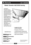
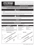
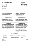
DIAGNOSTIC SERVICE MANUAL
A&E
SUNCHASER, 8500, 9000
Patio Awnings
USA
SERVICE OFFICE
Dometic Corporation
2320 Industrial Parkway
Elkhart, IN 46516
574-294-2511
CANADA
Dometic Distribution
46 Zatonski Unit 3
Brantford, Ontario
CANADA N3T 5L8
519-720-9578
REVISION
Form No. 3106934.015 9/07
(Replaces 3106934.007)
©2007 Dometic Corporation
LaGrange, IN 46761
Safety Instructions
This manual has safety information and instructions to help users eliminate or reduce the risk
of accidents and injuries.
Recognize Safety Information
This service manual is the result of the
dedication of The Dometic Corporation
Technical, Warranty and its engineering
staff in giving service people the necessary instruction for making accurate
analyses of certain conditions. Provided
is a diagnostic chart leading a qualified
mechanic into the service manual pages
to locate and solve symptoms which may
occur. Dometic has continued its commitment in providing service people with this,
the most up-to-date information about
servicing Dometic RV accessories.
This is the safety-alert symbol. When you see this
symbol in this manual, be alert to the potential
for personal injury.
Follow recommended precautions and safe operating instructions.
Understand Signal Words
A signal word , WARNING OR CAUTION is used
with the safety-alert symbol. They give the level
of risk for potential injury.
Indicates a potentially hazardous situation which, if not avoided, could result
in death or serious injury.
Indicates a potentially hazardous situation which, if not avoided may result in
minor or moderate injury.
When used without the safety
alert symbol indicates, a potentially hazardous
situation which, if not avoided may result in property damage.
Read and follow all safety information and instructions.
CONTENTS
PAGE NO.
Diagnostic Flow Chart...................................................................4
Section 1
Operation
1.1
1.2
Open............................................................................................................ 5
Close........................................................................................................... 6
Section 2
Hardware Components
2.1
2.2
2.3
2.4
2.5
2.6
2.7
2.8
Special Nut.................................................................................................. 8
Black Adjustment Knob............................................................................. 8
Lift Handle Lock Button............................................................................. 8
Adjustable Arm Assembly......................................................................... 8
Top Mounting Bracket............................................................................... 9
Bottom Mounting Bracket......................................................................... 9
Stop Plug.................................................................................................. 10
Rafters....................................................................................................... 10
Section 3
Fabric Roller Tube Assembly (FRTA)
3.1 Fabric........................................................................................................ 10
3.2
3.3
3.4
3.1.1 Position............................................................................................ 10
3.1.2 Tek Screws....................................................................................... 10
3.1.3 Square.............................................................................................. 11
3.1.4 Seams............................................................................................... 11
3.1.5 Stitches............................................................................................ 11
3.1.6 Fabric / Roller / Torsion Change.................................................... 11
Pull Strap.................................................................................................. 17
Roller Tube................................................................................................ 17
Torsions.................................................................................................... 17
3.4.1 Cam Lock......................................................................................... 17
Awning Rail............................................................................................... 17
Sidewall..................................................................................................... 17
Section 4
Other
4.1
4.2
This program will address the most common system problems associated with the A&E Patio Awnings supplied by Dometic
Corporation. Our intent is to provide you with a guideline of checks to make, should you encounter one of the following
symptoms.
Symptom
Cause
Refer To
Page
1. Black adjustment knob will not tighten
Special Nut
Knob
2.1
2.2
8
8
2. Main support arm will not extend
Lift Handle Lock Button
Adjustable Arm
2.3
2.4
8
8
3. Awning will not roll up straight
Fabric Position
Fabric Square
3.1.1
3.1.3
10
11
4. Weatherguard wrinkled
Seams
Sidewall
3.1.4
4.2
11
17
5. Fabric does not hang well
Tek Screws
Tube Deflection
Sidewall
Out of square
Stitches
Seams
3.1.2
3.3
4.2
3.1.3
3.1.5
3.1.4
10
17
17
11
11
11
6. Must lift arm (s) to open awning
Stop Plug
Bottom Mounting Brackets
2.7
2.6
10
9
7. Awning arm (s) stay up against side of
coach when trying to open awning
Top Mounting Brackets
Fabric Position
Operation
2.5
3.1.1
1.2
9
10
7
8. Awning will not roll up
Rafters
Black Adjustment Knob
Torsions
2.8
2.2
3.4
10
8
17
9. Awning will not stay in rolled down position
Cam Lock
3.4.1
17
10. Fabric leaks at roller tube
Stitches
3.1.5
11
11. Awning stops at guard when rolling up
Rafters
Stop Plug
Torsions
Awning Rail
Top Mounting Bracket
Operation
2.8
2.7
3.4
4.1
2.5
1.2
10
10
17
17
9
7
Operation
1.1 To Open
3. Extend FRTA
1. Loosen Knob and Unlock Hardware
Loosen
Knob
3
Hook the rod in loop, and pull all the way out.
Sunchaser:
Squeeze
4. Extend and Secure Rafters
8500/9000:
Flip
2. Unlock Fabric Roller Tube Assembily (FRTA)
Slide one rafter arm up until it snaps into place. Pull down
and out on the sliding rafter to remove slack from the fabric. Tighten the black adjustment knob. The tighter the
rafters are the better the fabric look and be less prown to
wind whipping. Repeat for other side.
Pull down.
Ensure the lock lever is not flipped to the “rollup” position prior to swinging the main arm
away from coach. Failure to do so can cause
damage to the lock mechanism.
Slide the pull strap to the right end of the tube and wrap
as shown.
1.2 TO CLOSE
5. Height Adjustment
1. From Patio Position
Pull stakes from the ground, lower arm to the shortest
position, swing arm toward the vehicle, and snap the patio
foot into the bracket. Repeat for other side and proceed
to next step.
Pull up on the lift handle and raise to desired height.
Swing handle down to lock button in hole. Repeat for
other side.
6. Carport Position
Ensure that the lock is in the “roll-down” position prior to swinging arms toward vehicle.
Failure to do so can cause damage to the lock
mechanism.
2. Lower Arms To Stop Bolts
Lower arm to shortest position. Press the release lever
and pull the arm away to a vertical position. Adjust height.
Drive stakes through holes in patio foot into the ground.
Repeat for other side.
Whenever heavy or prolonged rain or wind
is anticipated, or you will leave the awning
unattended, it is best to close the awning.
Damage as a result of weather is not covered
by warranty.
Raise the lift handle to release the lock button. Lower main
arm to the stop plug. Swing the handle down to engage
the lock button in a hole. Repeat for other side.
3. Loosen knob and release slider
7.Rain Position
During light rain, lower end opposite from door to shed
water and prevent pooling.
Slide the rafter arm down to the bottom of the main arm.
Leave black adjustment knob loose. Repeat for other
side.
4. Roll Up FRTA.
HELPFUL HINTS FOR AWNING CARE
•
Grasp the pull strap, pull toward you, and flip the locking
lever up to the ROLL UP position.
Do not release the awning pull strap now. It
is under tension and could snap back against
the vehicle side.
Slide the pull strap to the center, and using it to control
speed, allow the awning to return to the vehicle side.
Note: Allow the strap to wind diagonally to prevent a bulge
in the fabric.
On the 9000 series, when rolling up the awning, the roller
tube assembly should not be slowed down before reaching the aluminum guard. This could cause the roller tube
to stall at the guard.
Tighten black adjustment knob.
Sunchaser Awnings: Squeeze rafter into arms to engage
latch.
8500 & 9000: Flip travel lock latch down.
Repeat for other side. Your awning is now ready for
travel.
Whenever the awning is wet while rolled up, as soon
as conditions allow, roll it out and let it dry before rolling
it up again. This will help prevent mildew.
• Mildew does not form on the fabric itself, but on the
accumulated dust and dirt. Periodically clean vinyl or
woven acrylic.
• Always make sure the awning is extended high enough
before opening the entry door.
• Apply silicone spray lubricant as needed to keep the
awning’s moving parts operating smoothly. For ease
of operation on hardware, rub candle wax on all sliding
surfaces.
8500 and 8300
• Abrasion and weather are vinyl’s worst enemies. To
avoid these problems, you will need to keep your
awning clean. Use a mixture of 1/4 cup dish soap, 1/4
cup liquid bleach and five gallons of warm fresh water.
Soap the top side of the fabric with this mixture, then
roll it up and let stand for five minutes. Rolling up the
awning will apply the mixture to the underside of the
fabric. Unroll the awning and hose off the top and bottom with clean water. Repeat if necessary and allow
to completely dry.
A&E 9000
• In addition to its beauty and soft translucence, woven
acrylic fabric offers the advantages of strength and
breath ability. It is water repellent, but because it is a
woven cloth, it is not water proof. To keep your acrylic
awning clean, simply hose it off occasionally and let it
dry. Do Not Scrub.
• Avoid touching the underside of the 9000 canopy when
it is wet. To do so will break the surface tension of the
water and encourage seepage through the fabric.
• Because acrylic is a woven fabric, shifting may occur
if the awning and pull strap are not centrally aligned
with the fabric roller tube while the awning is being
rolled up. If necessary, roll the awning out and adjust
the alignment.
SECTION 2
to be cut off for removal. Using a hack saw cut the knob
stud as close to the rafter as possible without hurting the
finish on the rafter. Replace with new nut, Part number
3307663.017. Dometic has used several versions of the
nut for the knob. The current nut will fit hardware back
to the first generation used in 1992. Prior to the special
nut the hardware used a nutsert to hold the knob tight
(930022). Apply spray lubricant to the threaded portion
of the nut and knob once a year or as needed for smooth
operation.
Hardware Components
Top Mounting Bracket
Main Rafter
Knob With Nut
Knob With Nut
Secondary Rafter
Slider
2.2 Black Adjustment Knob
The black adjustment knob tightens the secondary rafter
to the main rafter to keep the fabric taut in the full open
position. When closing the awning, the knob should not
be tightened down until after the awning is rolled up and
the travel lock is engaged. Attempting to open the awning without first loosening the black adjustment knobs
can damage the slider of the secondary rafter, making it
difficult to open the awning. Apply spray lubricant to the
threaded portion of the knob once a year or as needed for
smooth operation. If knob is frozen to nut it will need to be
replaced with part number 3105421.014.
Main Support Arm
Slider Catch
Travel Lock
Lift-Lock Handle
2.3 Lift Handle Lock Button
The push button of the lift-lock assembly locks the main
support arm to the adjustable arm assembly and controls
the height of the awning in the open position. To check it,
open the awning to full extension. Look inside the mainsupport arm, and activate the button to see if the locking
pin is moving in and out of the hole in the adjustable arm
assembly. If the locking pin does not move, or has been
broken off, the lift handle assembly must be replaced. At
times the lock pin of the lift handle assembly can break off
and jam between the lift handle assembly and the adjustable arm assembly, making it difficult to extend the main
support arm. Replacement part number 830582.001(X).
To replace the lift handle assembly open the awning and
remove the adjustable arm assembly. Drill out the two
3/16 pop rivets and install the new lift handle assembly.
Adjustable Arm
Bottom Mounting
Bracket
2.1 Special Nut
The special nut is simply a threaded fastening device used
to tighten down the black adjustment knob. If the knob
will not tighten, first remove the secondary rafter assembly from the hardware. Turn the knob to determine if the
nut is stripped or spinning. If so, replace the special nut.
If you cannot turn the knob it will be necessary to replace
both the special nut and the black adjustment knob. To
replace the nut, open awning and remove the two screws
at the bottom of the main arm that keeps the rafter from
sliding out. The rafters won’t come apart until the knob
is removed from the nut. If the knob is frozen it will need
2.4 Adjustable Arm Assembly
The adjustable arm assembly allows for telescoping height
adjustment of the main support arm and it connects to the
bottom mounting bracket to support the weight of the awning. If the main support arm cannot be extended freely,
the adjustable arm assembly should be checked.
Remove the adjustable arm assembly and check for nicks,
burrs, bends or twists. If any deflection is noted, the adjustable arm assembly must be replaced. For ease of operation, rub candle wax on all sliding surfaces. To remove
an adjustable arm that has been bent and forced back into
the main support arm, remove the complete main support
arm. Using another adjustable arm as a slide hammer
come in from the top and remove the bent adjustable arm.
Chances of the main arm being bent would be slim. Once
the bent adjustable arm is removed, a new arm should go
back in and work OK.
Awning Rail With
Drip Channel
#14 x 3" Hex
Head Screw
Top Pivot
Note: A bent adjustable arm is not a warranty item. If the
arm was straight at delivery and unit is bent now, something has bent the arm; as improper operation or an act
of nature.
Rafter
2.5 Top Mounting Bracket
The top mounting bracket supports the main rafter assembly and holds the awning in the open extended position. This allows the rafter to pivot toward the roller
tube. The most common mounting location for each top
mounting bracket would be directly over the awning rail
so the screws go through the “C” portion of the rail. On
the Series 9000 awning the top mounting bracket can be
mounted lower when possible for better coverage in the
closed position. If the top mounting bracket is mounted
above center of the awning rail, the aluminum guard will
not cover the fabric properly. If this is the case, relocate
the top mounting bracket accordingly. Over the years A&E
has used a variety of Top Mounting Brackets on different
hardware. Today’s Top Mounting Bracket should mount
on the A&E hardware going back to late 1980. All brackets have slotted holes for the mounting screws, allowing
them to be adjusted side to side for proper alignment.
To adjust the brackets, close the awning and sight down
the main support arm and the main rafter. The clearance
on each side of the rafter should be approximately 1/4
inch. If clearance is not correct, adjust the top mounting
bracket(s) as necessary. On coaches with combination
drip/awning rail a stand off may be needed for proper operation and to keep the roller tube from hitting the rail.
Part number 3109623.003.
Awning Rail With
Drip Channel
#14 x 3" Hex
Head Screw
Mount Top Bracket
Over Awning Rail
Top Pivot
Rafter
#14 x 3" Hex
Head Screw
Awning Rail With
Drip Channel
Top Bracket Leg
Mounted On Awning Rail
Top Pivot
Mount Top Bracket
Over Awning Rail
Rafter
Awning
Rail
#14 x 3" Hex
Head Screw
Mount Top Bracket
Below Awning Rail
2.6 Bottom Mounting Bracket
The bottom mounting brackets are screwed to the floor
line of the unit and they support the weight of the awning.
They also provide a quick release to setup the awning in
the patio position. If a bottom mounting bracket settles,
sags, or becomes loose it can reduce the clearance between the top casting of the torsion and the extension
of the top mounting bracket, making operation difficult.
Check the bottom mounting bracket for looseness or settling, and tighten or reposition accordingly for proper operation. A stand off is available and goes over molding
and extends the Bottom Mounting Bracket away from the
side of the coach approximately 3/4 inch if needed.
Top Pivot
Rafter
Section 3
Fabric Roller Tube Assembly (FRTA)
The fabric roller tube assembly consist of Fabric, Aluminum Guard (858 & 9000 only), Roller Tube and Torsions.
Each component can be diagnosed, then repaired or replaced. The 9000 fabric is woven acrylic, not canvas. In
addition to its beauty and soft translucence, woven acrylic
fabric offers the advantages of strength and breath ability. It is water repellent but because it is a woven cloth,
it is not water proof. To keep your acrylic awning clean,
simply hose it off occasionally and let it dry. Do Not Scrub.
Avoid touching the underside of the 9000 canopy when it
is wet. To do so will break the surface tension of the water and encourage seepage through the fabric. Because
the acrylic is woven not a solid vinyl, shifting may occur
if the awning and pull strap are not centrally aligned with
the fabric roller tube while the awning is being rolled up.
If necessary, roll the awning out and adjust the alignment
as you close the awning. The 8300 and 8500 is a vinyl,
nylon reenforced fabric. Abrasion and harsh weather are
vinyl’s worst enemies. To avoid abrasion, you will need to
keep your awning fabric clean. Use a mixture of 1/4 cup
dish soap, 1/4 cup bleach and five gallons of fresh water.
Soap the open awning with this mixture, then roll it up and
let stand for five minutes. Rolling up of the awning will apply the mixture to the underside of the fabric. Unroll the
awning and hose off the top and bottom with clean water.
Repeat if necessary and allow to completely dry.
Molding
Bottom Wall Bracket
Standoff Kit 3104781.XXX
2.7 Stop Plug
The stop plug is a mechanical stop that supports the main
arm when opening and closing the awning. It controls the
clearance between the top casting of the torsion and the
extension of the top mounting bracket. This clearance
should be 1/4 inch to 1 inch. To adjust the clearance, raise
or lower the stop plug as needed. On the 9000 Series
awning the clearance should be kept to a minimum for
best operation.
3.1 Fabric
Main Arm
3/8" Dia. Hole
3/8”
Closest To
Main Arm
5/16" - 18
Lock Nut
Inner Arm
5/16" - 18 x 1"
Shoulder Bolt
2.8 RAFTERS
The rafters telescope from the top mounting brackets to
the main support arms to provide tension on the fabric in
the full open position. If the rafters are bent or twisted,
this will hinder the operation of the awning. Open the awning and remove the secondary rafter from the main support arm. Sight down the main and secondary rafters and
check for any bends, twists or deflection. If one or the
other rafter is not true it should be replaced.
Note: A bent rafter arm is not a warranty item. If the arm
was straight at delivery and unit is bent now, something
has bent the arm as improper operation or an act of nature.
10
3.1.1 Position
For the awning to operate properly the fabric must be
positioned properly in the awning rail and on the roller
tube. Open the awning and check the position of the fabric
between the top mounting brackets. If the fabric is not
centered, remove the tek screws, center it, and replace the
screws. Once the fabric at the rail is properly positioned,
next check the position of the fabric on the roller tube.
The clearance from the end cap of the torsion assembly
to the edge of the fabric must be the same on each end.
If it is not, adjust the fabric on the tube as necessary. On
the Elite 9000 and 9500 awning the fabric is held in place
to the weatherguard with set screws. Check the position
of the fabric at each end of the weatherguard. If the fabric
has shifted, remove set screws, center the fabric and reset. An awning that the fabric has shifted will open and
close hard.
3.1.2 TEK Screws
The Tek screws are the two screws installed through the
awning rail of the coach. They keep the fabric from shifting in the awning rail. On vinyl and acrylic awnings they
keep the poly rope in the fabric from shrinking with age.
If one Tek screw is missing, the fabric will pull toward the
remaining Tek screw causing the fabric to wrinkle. With
the awning open, remove the tek screws and pull outward
on the fabric, stretch it, and re secure the screw. Do this
on both sides to assist with the wrinkles at the weather
guard and fabric. If wrinkles are still present, repeat the
above stretching procedure. This may have to be done 4
or 5 times before all wrinkles disappear.
problem. If so, fabric replacement would be needed.
Whenever wrinkles are detected in the fabric, stretching
of the weatherguard should be performed before the fabric is condemned for bad seams. See 2.1.2 for stretching
instructions.
3.1.5 Stitches
The side hems and poly ropes of the awning are stitched
in with a sewing machine. At times the stitches can allow
water to leak through to the inside of the roller tube. On
vinyl awnings the stitches should be sealed with seam
sealer, available at sporting goods stores. This will stop
the water from running down the inside of the roller tube.
For the woven acrylic fabric of the 9000, 9500 Series awning, scotch guard is an approved sealant. When sewing in the poly ropes of the fabric, if a straight line is not
followed, it could cause the fabric to hang improperly. A
close inspection of the stitching could reveal the cause of
a sag or pucker.
3.1.6 Fabric/Roller/Torsion Change
In all instances of fabric or roller tube replacement, it will
be necessary to have a large work area to allow complete
unrolling of the awning. This work area must be clean and
smooth so the fabric will not be damaged. Remove the
awning from the coach and carefully lay on the ground.
To keep the awnings from unwinding during this step, be
sure the cam lock lever is in the roll down position. The
spring tension should be pinned on both torsions for ease
and safety for removal of awning.
Sunchaser 8300 Torsion Pinning.
To keep the awning from unwinding be sure the lock lever
is in the roll down position and a nail inserted in each torsion assembly for positive locking of the roller tube. The
left end should be done first. Insert a nail into hole on the
left end cap. Grasp roller assembly and release Safe-TLock™ lever. Allow awning to roll up slowly until it stops
against the pin. Insert the pin into the right end cap to hold
it in place. Complete instructions Form 3105903.XXX
3.1.3 Square
If the fabric on the awning is out of square, it could cause
the fabric to telescope in one direction when rolling up, or
to not hang properly in the open position. To check fabric
for square, measure from the top right hand corner of the
fabric (not the weatherguard) to the bottom left hand corner at the poly rope. Now measure from the top left hand
corner to the bottom right hand corner as shown below.
AWNING
RAIL
Severe injuries can result from the rapid
spin off of the top casting. Use Vise Grips®
- NEVER use bare hands - to handle a top
casting under spring tension.
FABRIC
1ST POLY
ROPE
ROLLER
TUBE
DISTANCE FROM FABRIC TO END CAP (SAME ON EACH END)
In this check, the difference of the two dimensions should
be no more than one inch. If it is more, the fabric is out of
square, and replacement would be necessary.
3.1.4 Seams
The seams of the vinyl awning are electronically welded together with a heat seal. The welded seams are the
strongest part of the fabric. If the fabric has wrinkles or
sags, it may be due to improper seam welding. A close
inspection may reveal the seams to be the source of the
11
8500 & 9000 Torsion Pinning
To keep the awnings from unwinding during this step, be
sure the cam lock lever is in the roll down position. A 1/8”
cotter pin can be inserted in each torsion assembly for
positive locking of the roller tube. Complete instructions
Form 3107299.XXX.
MOVE LEVER POSITION TO
ROLL DOWN POSITION
TOP CASTING
TOP
CASTING
LOCK
LEVER
VISEGRIPS®
RIGHT-HAND SIDE
(VIEWED FROM FRONT)
1/4-20 X 1/2" HEX
HD. MACH. SET SCREW
MAIN SUPPORT
ARM ASSEMBLY
Crank
3107905.006
COTTER
PIN
LOCK
LEVER
TOP
CASTING
Improper release of this spring tension
can result in damage
to
the
awning, severe
personal
injury, or both.
MAIN SUPPORT
ARM ASSEMBLY
Severe injuries can result from the rapid spin
off of the top casting. Use Vise Grips® - NEVER
use bare hands - to handle a top casting under
spring tension.
1/4 - 20 X 1/2" HEX
HD. MACH. SET SCREW
Carefully lay the fabric roller tube assembly on a clean,
well padded “V” trough to prevent fabric damage. Remove the arm assemblies from the respective torsion rod,
by removing the 1/4”–20 machine screws.
8500 & 9000
Clamp a Vise Grip® tightly on the top casting, or insert
the crank (3107905.006/3308334.006U) into top casting.
Remove the 1/4-20 hex head machine screw from the top
casting. Take the top casting carefully out of the main support arm. Slowly let the torsion spring unwind completely.
Repeat Steps 1 & 2 for the opposite end. NOTE: If the
awning’s right-hand torsion assembly has been pinned,
the cotter pin must be removed from the torsion assembly
before the spring can be unwound. The cam lock lever on
the right-hand torsion assembly must be turned clockwise
to the roll up position, before the spring can be unwound.
Always note and or mark the location of cam lock on roller
tube.
Severe injuries can result from the rapid spin
off of the top casting. Use Vise Grips® - NEVER
use bare hands - to handle a top casting under
spring tension.
12
Roll the awning completely out on a clean smooth surface.
With the awning laying flat, slide the roller tube out from
fabric. The metal roller cover on 8500 and 9000 models
may be crimped to the poly ropes. Use needle Nose pliers and flat blade screw driver to spread open the channel
before removing fabric. On newer units the guard is held
to the fabric with a set screw at the ends of the channel,
remove the set screws and slide the guard off the fabric.
Sunchaser 8300
Carefully lay the fabric roller tube assembly on a clean,
well padded “V” trough to prevent fabric damage. Remove the right arm assembly from the respective torsion
rod, by removing the 1/4" - 20 machine screws and 1/4"
locknuts. Lift the right end of the awning and roll the FRTA
assembly clockwise one-half turn or until roll pin (inside
end cap) is stopped against the nail. Remove the left arm
assembly from the torsion rod by removing the 1/4" – 20
machine screws and locknuts. Insert torsion winding 3/4"
hex head stud into the end of the torsion rod. Insert 1/4"
pin through 3/4" deep well socket over hex stud. Slide the
3/4" deep well socket over hex stud until it locks 1/4" pin
in place. Insert speed wrench or breaker bar into socket.
Remove the pin from the end cap. It may be necessary
to turn torsion rod to release pressure from pin, making it
easier to remove.
Note: On right hand torsion, move the Safe-T-Lock™ lever to the roll-up position. Always note and or mark the
location of cam lock on roller tube.
Note: Some 9000 model awning secured the fabric to the
roller cover with 1/8” pop rivets. It is necessary to remove
the 1/8” pop rivets from both ends of the roller cover. Once
the rivets are removed, you can slide the fabric out of the
cover.
Unfold the new fabric and lay it on top of the existing fabric in the exact same position. Be sure the new fabric is
the correct size and color. If roller tube is being replaced,
make sure it is the correct length and position it with the
notch located as shown.
ROLLER
TUBE
FABRIC
GROOVE
OPEN
GROOVE
VALANCE
ROPE
NOTCH
Improper release of this spring tension can
result in damage to the awning, severe personal injury, or both.
Once the tension has been removed, mark the location
of the cam lock lever on the roller tube and drill out the
rivets with a 3/16 drill bit and remove the torsion from the
roller tube.
13
PLACE END
CAP GUIDE
ON ROLLER
TUBE
SLIDE FABRIC
AND
VALANCE
ROPES
THROUGH
GUIDE
Dometic requires the use of the end cap guide to prevent
damages to the fabric, when replacing the fabric/roller
tube. Place the end cap guide supplied with the replacement fabric/roller tube on the end of the roller tube. Slide
the fabric and valance ropes through the end cap guide
and onto the roller tube.
Note: When changing the fabric, it is vital that the same
grooves be used. This eliminates the need to redrill any
holes (i.e. center support).
Position the right-hand torsion assembly open hole in the
end cap in alignment with the empty groove in the roller
tube. If a new right-hand torsion assembly is being installed and the roller tube does not have the notch shown,
the two tabs inside the right-hand torsion end cap must be
broken off. Secure torsion assemblies to roller using 3/16"
dia. x 3/8" long pop rivets.
Guide the roller tube over the poly-ropes of the fabric. Be
careful not to damage the roller tube or the fabric. Install
the pull strap. Center the fabric on the roller tube and
hand-roll the entire assembly in the same direction as the
original fabric.
Note: The number of sections in the Aluminum guard
can vary from each model number. The standard was 6
sections for the 9000 series awning in the early nineties.
Today’s 9000 and 8500 series awnings come with 5 sections of guard. When installing a new fabric on an older
9000 series awning one section will have to be removed.
break off two
locating tabs
To reduce the possibility of the poly rope interfering with
the cam lock mechanism, the right-hand torsion requires
the valance rope to be cut off even with the roller tube.
The poly rope on the fabric side is cut 6” longer than the
roller tube. Stretch the poly rope and pull it toward the
center of the roller tube. Make sure it is locked in the
notch of the groove in the roller tube. Reinstall the torsion
assembly in the roller tube. Align the rivet slots on the end
cap with the holes in the roller tube - in the exact same
position as the original. If a new roller tube is being used
make sure the fabric has been installed as the original
unit. The poly ropes on the left-hand end of the roller tube
should be trimmed in the same as the right hand, then
install the left hand torsion.
ROLLER TUBE
FABRIC
VALANCE
STRETCH FABRIC ROPE
TIGHT AND PULL DOWN
AND INTO THE CENTER
OF ROLLER TUBE. MAKE
SURE IT IS LOCKED
IN THE NOTCH ON
THE BOTTOM OF THE
GROOVE.
CUT VALANCE ROPE EVEN WITH
THE END OF THE ROLLER TUBE
NOTE: Placing the end caps as suggested usually positions the lock lever in the proper position when awning is
closed. The awning should be opened and closed several
times, and checked. The cam lock lever should be at the
“11:00” position when awning is in the closed position.
The end cap may have to be removed and repositioned if
it is not in the proper location.
SPRING IDENTIFICATION CHART
Wire Dia.
RH
LH
14
Heavy Duty
0.135
0.148
Painted red
cap end and
no paint on
stabilizer
end.
8500 and 9000 Torsion Identification
Models 8500 and 9000 19' - 25' have been manufactured with both standard and heavy duty torsion
springs. Before reinstalling the torsion, properly
identify (Standard or Heavy Duty) the springs. This
is necessary for proper winding of the torsion. See
Spring Identification Chart.
Standard
No paint on
either end.
Painted red cap end and
blue on stabilizer end.
Painted yellow cap end,
red on stabilizer end.
Painted white
on cap end
and black
on stabilizer
end.
Painted blue
cap end and
no paint on
stabilizer
end.
Painted yellow on cap
end, no paint
on stabilizer
end.
Painted black
on stabilizer
end and no
paint on cap
end.
Current guards have a set screw in the channel. Reinstall
the set screw to keep fabric from shifting.
15
Torque chart for Sunchaser 8300 awnings.
Torque chart for 8500 and 9000 series awnings.
TORSION WINDING FOR LARGE STABILIZER 8300
8500&9000 TORSION ASSEMBLY
Awning
Length
(Ft.)
TORQUE SPECIFICATIONS
Model 8500 & 9000
Standard
Number of Turns
8
8'6"
9
10
10'6"
10' 8"
11
11'6"
12
13
14
14'6"
15
15'6"
16
16'1"
16'6"
17
18
18'6"
19
19'6"
20
20'6"
20'9"
21
21'9"
22
23
24
25
Model 8500 & 9000
Heavy Duty
Number of Turns
8
8
8
8
8
8
8
8
8
9
9
9
10
10
10
10
12
12
12
12
12
12
12
12
12
12
12
12
12
12
12
–
–
–
–
–
–
–
–
–
–
–
–
–
–
–
–
–
–
–
–
8
8
8
8
8
8
8
8
8
8
8
AWNING LENGTH
TURNS UP
TURNS OPEN
8 FT
9 FT
10 FT
11 FT
12 FT
13 FT
14 FT
15 FT
16 FT
17 FT
18 FT
19 FT
20 FT
21 FT & ABOVE
5
5
5
5
5
6
6
7
7
9
9
10
10
10
11
11
11
11
11
12
12
13
13
15
15
16
16
16
L
TORSION WINDING FOR SMALL STABILIZER 8300
Once the torsion have been wound, lock the tension on
the 8500 - 9000 with a long cotter pin, on the 8300 sunchaser awning use a nail. Now the awning can be reinstalled back on the coach. Follow the instalation instructions for the model awning you are working on.
AWNING LENGTH
TURNS UP
TURNS OPEN
8 FT
9 FT
10 FT
11 FT
12 FT
13 FT
14 FT
15 FT
16 FT
17 FT
18 FT
19 FT
20 FT
21 FT & ABOVE
8
8
8
8
8
9
9
10
10
12
12
12
12
12
14
14
14
14
14
15
15
16
16
18
18
18
18
18
S
16
3.4.1 Cam Lock
The cam assembly locks the roller tube from turning in
one direction or the other according to which way the cam
lock lever is flipped. To check the cam lock on the A&E
awning, unlock the main support arms. Hook the pull rod
into the pull strap and try to open the awning. Be sure the
cam lock lever is in the roll-up position. If the roller tube
rotates 1/2 turn or more the cam lock must be replaced.
To check the roll-down position of the cam lock, open the
awning to full extension. Grasp the roller tube with your
hands and try to turn the tube in the direction it will roll up.
If the tube can be rotated 1/2 turn or more the cam lock
must be repaired or replaced.
3.2 Pull Strap
When closing the awning the pull strap should be rolled
up at an angle from the center of the roller tube. This will
keep the awning from telescoping forward or rearward,
and will prevent a bulge from forming in the area where
the strap is rolled up. If the pull strap is rolled up at one
end of the awning, it can cause the fabric to telescope in
that direction during roll-up, and create a bulge or wrinkles at that end. This could cause the awning arm to stay
against the side of the coach when trying to open.
3.3 Roller Tube
The roller tube is a 3-1/2 inch diameter tube. It has 3 symmetrical grooves to retain the poly ropes of the awning
fabric. If the fabric appears to have more than normal sag,
the roller tube deflection must be taken into consideration.
Depending on the length of the awning, the roller tube can
deflect from one to five inches with the awning in the open
position. Installing a tension rafter will usually remove 80
per cent of sag and roller tube deflection. All awnings 22
feet and longer must be installed with heavy duty hardware which includes a center tension rafter, a center supporter, and heavy duty adjustable arm assemblies. If the
roller tube is bent, it will bounce up and down when
opening and closing the awning.
Section 4
Other
4.1 Awning Rail
Note: A Roller Tube that is snapped in the center is not
a warranty item. This is normally caused by an act of nature.
3.4 Torsions
The torsion assembly has a wound coil spring which provides tension on the roller tube to roll the awning up into
the travel position. The right hand torsion end cap contains
a cam assembly which prevents the awning from billowing
or unrolling during travel. It also allows one-person set-up
of the awning by preventing rollback. When difficulties are
experienced in rolling the awning up, the tension on the
torsion should be checked. In most cases adding a few
turns of torque to each end will correct the problem. If all
tension has been lost, refer to the following chart and apply the specified number of turns as indicated. This must
be done with the awning extended two feet away from the
coach. Reference fabric change for torsion winding.
There are three types of awning rail openings used in
the RV industry. Of these, type A and B are acceptable
for use on the 9000 Series awning. Type C should never
be used on the 9000 Series awning as it could cause a
binding problem on the aluminum guard assembly, but it
is acceptable on the vinyl awnings.
On coaches with combinations drip/awning rail a stand off
may be needed for proper operation and keep the roller
tube from hitting the rail. Part number 3109623.003.
4.2 Sidewall
Before condemning the fabric for sags or wrinkles, the
awning rail and sidewall should be checked. Open the
awning and sight down the rail to see if the rail or sidewall
varies up, down, inward or outward. This must be taken
into consideration when checking a fabric.
Severe injuries can result from the rapid
spin off of the top casting. Use Vise Grips®
- NEVER use bare hands - to handle a top
casting under spring tension.
17