1
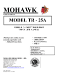
MOHAWK
INSTALLATION-OPERATION-SERVICE MANUAL
ELECTRIC-HYDRAULIC
LIFT
4-POST ARRANGEMENT
WITH DRIVE-ON RUNWAYS
MODELS:
TR-30
CAPACITY: 30,000
MOHAWK RESOURCES LTD.
65 VROOMAN AVENUE
P.O. BOX 110
AMSTERDAM, NY 12010
TOLL FREE: 1-800-833-2006
FAX:
1-518-842-1289
LOCAL:
1-518-842-1431
File: TR-30-40-60.doc
Rev: 6/16/2003
TR-40
40,000
TR-60
60,000 Lb
READ MANUAL THOROUGHLY
BEFORE INSTALLING,
OPERATING OR MAINTAINING
LIFT!!
SAFETY INSTRUCTIONS:
1. Read all instructions.
2. Inspect lift daily. Do not operate if it malfunctions or problems have been encountered.
3. Never attempt to overload the lift. The manufacturer's rated capacity is shown on
the identification label on the power side column. Do not override the operating
controls or the warranty will be void.
4. Only trained and authorized personnel should operate the lift. Do not allow
customers or bystanders to operate the lift or be in the lift area.
5. Position the lift support pads to contact the vehicle manufacturer's recommended lifting points.
Raise the lift until the pads contact the vehicle. Check pads for
secure contact with the vehicle, then raise the lift to the desired working height.
6. Some pickup trucks may require an optional truck adapter to clear running boards or other
accessories.
NOTE: Always use all 4 arms to raise and support vehicle.
7. Caution! Never work under the lift unless the mechanical safety locks are engaged.
8. Note that the removal or installation of some vehicle parts may cause a critical load shift in the
center of gravity and may cause the vehicle to become unstable. Refer to the vehicle
manufacturer's service manual for recommended procedures.
9.
Always keep the lift area free of obstructions and debris. Grease and oil spills should always
be cleaned up immediately.
10. Never raise vehicle with passengers inside.
11. Before lowering check area for any obstructions.
12. Before driving vehicle between the towers, position the arms to the drive-through position to
ensure unobstructed clearance. Do not hit or run over as this could damage the lift and/or
vehicle.
13. Before removing the vehicle from the lift area, position the arms to the drive-through position
to prevent damage to the lift and/or vehicle.
14. Care must be taken as bums can occur from touching hot parts.
15. Do not operate equipment with a damaged cord or if the equipment has been dropped or
damaged until a qualified serviceman has examined it.
16. Do not let cord hang over the table, bench or counter or come in contact with hot manifolds or
moving fan blades.
17. If an extension cord is necessary. a cord with a current rating of two or more than that of the
equipment should be used. Cords rates for less current than the equipment may overheat.
Care should be taken to arrange the cord so that it will not be tripped over or pulled.
18. Always unplug the equipment from electrical outlet when not in use. Never use the cord to pull
the plug from the outlet. Grasp plug and pull to disconnect.
19. To reduce the risk of fire, do not operate equipment in the vicinity of open containers of
flammable liquids (gasoline).
20. Adequate ventilation should be provided when working on operating internal combustion
engines.
21. Keep hair, loose clothing, fingers, and all parts of body away from moving parts.
22. To reduce the risk of electric shock, do not use on wet surfaces or expose to rain.
23. Use only as described in this manual. Use only manufacturer's recommended attachments.
24. ALWAYS WEAR SAFETY GLASSES. Everyday eyeglasses. only have impact resistant
lenses, they are NOT safety glasses.
SAVE THESE INSTRUCTIONS
MOHAWK WARRANTIES
EFFECTIVE DATE: 4/14/2003
GENERAL WARRANTY INFORMATION:
MOHAWK’S OBLIGATION UNDER THIS WARRANTY IS LIMITED TO REPAIRING OR REPLACING ANY PART OR PARTS RETURNED TO THIS FACTORY,
TRANSPORTATION CHARGES PREPAID, WHICH PROVE UPON INSPECTION TO BE DEFECTIVE AND WHICH HAVE NOT BEEN MISUSED. DAMAGE OR
FAILURE TO ANY PART DUE TO FREIGHT DAMAGE OR FAULTY MAINTENANCE IS NOT COVERED UNDER THIS WARRANTY. THIS WARRANTY DOES NOT
COVER ANY CONSEQUENTIAL OR INCIDENTAL DAMAGES INCLUDING, BUT NOT LIMITED TO, LOST REVENUES OR BUSINESS HARM. THIS EQUIPMENT
HAS BEEN DESIGNED FOR USE IN NORMAL COMMERCIAL VEHICLE MAINTENANCE APPLICATIONS. A SPECIFIC INDIVIDUAL WARRANTY MUST BE
ISSUED FOR UNITS THAT DEVIATE FROM INTENDED USAGE, SUCH AS HIGH CYCLE USAGE IN INDUSTRIAL APPLICATIONS, OR USAGE IN EXTREMELY
ABUSIVE ENVIRONMENTS, ETC.. MOHAWK RESERVES THE RIGHT TO DECLINE RESPONSIBILITY WHEN REPAIRS HAVE BEEN MADE OR ATTEMPTED BY
OTHERS. THIS WARRANTY DOES NOT COVER DOWNTIME EXPENSES INCURRED WHEN UNIT IS IN REPAIR. THE MODEL NAME AND SERIAL NUMBER OF
THE EQUIPMENT MUST BE FURNISHED WITH ALL WARRANTY CLAIMS. THIS WARRANTY STATEMENT CONTAINS THE ENTIRE AGREEMENT BETWEEN
MOHAWK RESOURCES LTD. AND THE PURCHASER UNLESS OTHERWISE SPECIFICALLY EXPRESSED IN WRITING. THIS NON-TRANSFERABLE WARRANTY
APPLIES TO THE ORIGINAL PURCHASER ONLY. THIS WARRANTY IS APPLICABLE TO UNITS LOCATED ONLY IN THE UNITED STATES OF AMERICA AND
CANADA. CONTACT MOHAWK RESOURCES LTD. FOR SPECIFIC WARRANTY PROVISIONS FOR UNITS LOCATED OUTSIDE OF THESE COUNTRIES.
5-YEAR WARRANTY:
THIS WARRANTY IS APPLICABLE TO THE FOLLOWING MOHAWK LIFTS ONLY: A-7, SYSTEM IA, SYSTEM IA-10, TOMAHAWK9000, LMF-12, TP-15, TP-18, TP-20, TP-26, TP-30 AND STANDARD OPTIONS.
3-YEAR WARRANTY:
THIS WARRANTY IS APPLICABLE TO THE FOLLOWING MOHAWK LIFTS ONLY: TSL-7, PL-6000, TR-19, TR-25, FL-25, TR-33, TR35, TR-40, TR-50, TR-60, TR-75, TR-110, MP-SERIES AND RP-SERIES MOBILE COLUMN LIFTS, SL-SERIES SCISSOR LIFTS, FPSERIES LIGHT DUTY FOUR POST LIFTS, TL-SERIES LIFTS AND STANDARD OPTIONS.
2-YEAR WARRANTY:
THIS WARRANTY IS APPLICABLE TO THE FOLLOWING MOHAWK LIFTS ONLY: PARALLELOGRAM SERIES AND USL-6000
AND STANDARD OPTIONS.
1-YEAR WARRANTY:
THIS WARRANTY IS APPLICABLE TO THE FOLLOWING MOHAWK LIFTS ONLY: HR-6, TD-1000, CT-1000 AND STANDARD
OPTIONS.
STRUCTURAL COMPONENTS:
ALL STRUCTURAL AND MECHANICAL COMPONENTS OF THIS UNIT ARE GUARANTEED FOR THE ABOVE STATED TIME
FRAME, SPECIFIC TO MODEL, FROM THE DATE OF INVOICE, AGAINST DEFECTS IN WORKMANSHIP AND/OR MATERIALS
WHEN LIFT IS INSTALLED AND USED ACCORDING TO SPECIFICATIONS.
SEE MOHAWK’S “EXTENDED LIFETIME CYLINDER WARRANTY” FOR SPECIFIC WARRANTY PROVISIONS FOR HYDRAULIC
CYLINDERS. THE “EXTENDED LIFETIME CYLINDER WARRANTY” IS APPLICABLE TO THE FOLLOWING MOHAWK LIFTS ONLY:
A-7, SYSTEM I, LMF-12, TP-15, TP-18, TP-20, TP-26, TP-30, MP-SERIES AND TL-SERIES LIFTS.
POWER UNIT:
ALL POWER UNIT COMPONENTS (MOTOR, PUMP AND RESERVOIR) ARE GUARANTEED FOR THE ABOVE STATED TIME
FRAME, SPECIFIC TO MODEL, FROM THE DATE OF INVOICE, AGAINST DEFECTS IN WORKMANSHIP AND/OR MATERIALS
WHEN THE LIFT IS INSTALLED AND USED ACCORDING TO SPECIFICATIONS.
ELECTRICAL COMPONENTS:
ALL ELECTRICAL COMPONENTS (EXCLUDING MOTOR) ARE GUARANTEED FOR ONE YEAR FOR PARTS ONLY
(EXCLUDING LABOR), FROM THE DATE OF INVOICE, AGAINST DEFECTS IN WORKMANSHIP AND/OR MATERIALS WHEN
THE LIFT IS INSTALLED AND USED ACCORDING TO SPECIFICATIONS.
PNEUMATIC (AIR) COMPONENTS:
ALL PNEUMATIC (AIR) COMPONENTS (I.E. AIR CYLINDERS AND POPPET AIR VALVES) ARE GUARANTEED FOR ONE YEAR
FOR PARTS ONLY (EXCLUDING LABOR), FROM THE DATE OF INVOICE, AGAINST DEFECTS IN WORKMANSHIP AND/OR
MATERIALS WHEN THE LIFT IS INSTALLED AND USED ACCORDING TO SPECIFICATIONS.
WARRANTY EXCEPTIONS:
ALL “SPECIAL” LIFTS AND/OR “CUSTOMIZED” OPTIONS ON THIS UNIT ARE GUARANTEED FOR ONE YEAR FOR PARTS ONLY (EXCLUDING LABOR),
FROM THE DATE OF INVOICE, AGAINST DEFECTS IN WORKMANSHIP AND/OR MATERIALS WHEN THE LIFT IS INSTALLED AND USED ACCORDING TO
SPECIFICATIONS.
THIS WARRANTY SUPERSEDES ALL OTHER WARRANTY POLICIES PREVIOUSLY STATED AND IN ALL OTHER MOHAWK PRODUCT SPECIFIC LITERATURE.
4-POST LIFT INSTALLATION MANUAL:
This manual contains important installation and service instructions for the Mohawk
Electric/Hydraulic 4-post lift. Please read through this manual first, before installing, operating or
maintaining the lift(s), to ensure full comprehension of the procedures and methods of operation.
NOTE:
THE LIFT INSTALLER IS RESPONSIBLE TO GIVE ALL DOCUMENTS
TO THE LIFT OPERATOR.
If 3 phase unit check!
The rotation of the electric motor.
If the motor does not turn or turns anti-clockwise, rotate the wires in the power supply plug.
WARNING INSTALLERS!
BEFORE INSTALLATION:
Please ensure that you have proper incoming electric line power supply in the
building.
For single PHASE motors - each motor 220V – 20AMP service is required.
For 3 PHASE 230V – 10AMP for each motor.
If you don’t have that power contact lift manufacturer for instructions.
Do not install lift!
You will responsible for costs involve with changing motors or pumps to
accommodate low power supply.
TABLE OF CONTENTS
SECTION
DESCRIPTION
1
2
3
4
5
4-POST INSTALLATION INSTRUCTIONS
MAINTENANCE INSTRUCTIONS
AUTOMOTIVE LIFT SAFETY TIPS
TR-40-25 INSTRUCTIONAL DRAWINGS
TR-40-25 PARTS LIST DRAWINGS
NOTE:
THIS MANUAL IS BASED ON THE STANDARD TR-40
LIFT WITH 25’ TRACKS. MODELS TR-30 AND TR-60
HAVE SIMILAR INSTALLATION AND OPERATION
CHARACTERISTICS. USE THIS MANUAL AS A
GUIDELINE FOR THESE MODELS.
1. 4-POST LIFT INSTALLATION INSTRUCTIONS:
NOTE: DO NOT ANCHOR LIFT UNTILL REQUIRED BY THESE
INSTRUCTIONS.
1. Unpack the lift and identify parts
2. Locate on shop floor where the 4-post lift will be installed. (See Figure 1 for lift dimensions)
3. Identify the location of the power unit for the 4-post lift. (See Figure 6 for power unit placement
options)
4. Using Figure 2 as a guide, mark the footprint for each column on the shop floor. (Using chalk,
marker, or paint)
5. Place columns on marked footprints. (ensure that the main control column is placed at the power
unit)
6. Place crossbeams between the front and rear columns. (for ease of installation it is
recommended that the crossbeams be elevated slightly on wooden blocks)
7. Ensure that conduits are placed on the outside of the lift (See Figure 5)
8. Using Figure 3 as a guide, connect the wire rope cable to the wire rope anchor on the bottom of
each column and to the wire rope adjustment on the top of each column.
9. Using Figure 4 as a guide, install the Hydraulic Cylinder to the top of each column
10. Using Figure 1 and DWG FP4025001 as guides, place runways on the top of the crossbeams at
a desired wheelbase width. (For multipurpose use the recommended center gap between
runways is 48”)
11. Install power units (use Figure 1 & DWG FP4025001 as installation guide)
12. Connect hydraulic hose routing (use Figure 7, as installation guide)
13. Using Figure 8 as guides,
• connect the Air Line,
• Install electric box and bring power supply to electric control box,
• connect air supply to air filter lubrication system
14. Press air valve to check air lines for leaks
15. Fill the hydraulic fluid reservoir with 32 Grade Hydraulic Fluid
16. Adjust columns so that the crossbeam bearing shoes are even with the columns and fit between
the guides on the column
17. Check all hydraulic connections and ensure the all connections are tight
18. Connect power to power unit
19. Press “UP” button located on the electric control box
• elevate lift 2-3ft
• if lift does not move but motor noise is present, then check motor rotor rotation and adjust
as necessary
20. Lower Lift: To lower the lift, the operator must continuously hold down the “down button”
21. To remove air from hydraulic system raise and lower the lift 3-4 times to a maximum height of 3
feet
22. Raise the lift to the maximum limit and then lower
23. Ensure that all column and crossbeam connections are square (make adjustments as
necessary)
24. Ensure that columns are plumb (use shimmies for adjustment)
25. Anchor all columns using Figure 2 as guide
26. Use Figure 5 as guide for the installation of Front Stop and Approach Ramp Assembly
27. Using plastic ties and clamps connect all loose hydraulic and air lines.
28. Elevate the lift 3ft and engage the safety latches by pressing the down button (refer to Figure 4)
29. Adjust the level of runways and crossbeams by adjusting the ¾ NC Hex Nut on the top of each
lift (refer to Figure 4)
30. Use Figure 3 as guide to adjust wire rope tension (information is provided on Figure 3)
31. FINAL TEST: Elevate the lift to its limit and hold for no more then 4 seconds. This will test the
lifting system for maximum load capacity. Following this test: CHECK FOR ANY HYDRAULIC
FLUID LEAKS and tighten any loose connections as necessary.
32. Lower Lift: To lower the lift, the operator must continuously hold down the “down button”.
2. MAINTENANCE INSTRUCTIONS:
1. The 4-post lift does not use bearings or seals that require regular or frequent lubrication. The
column sections where the crossbeam slider blocks ride should be greased once a year
using a high-pressure grease.
2. The power supply and interconnecting cables should be checked daily, or if the lift has not
been used for a period of time, to ensure that there are no nicks or cuts which may reduce
the insulation. Also, an inspection is recommended to check the hydraulic hose connections
for leaks and tighten or repair as necessary.
3. The hydraulic fluid should be changed once every two years using a good quality ISO32
HYDRAULIC OIL. It is necessary only to drain the reservoir tank when the cradle is in the
lowered position. Add 3US Gal. (12 litres).
4. Every three months check and re-tighten bolts on wheels, power unit and carriage lock rack
attachment. Apply a light coating of grease to the column rails front and rear.
5. In case of electrical break down have qualified service personnel service the lift Always refer
to Operation manual when operating lift.
6. Call your Distributor or Factory direct if you have any questions with regards to operating the
lift.
7. The visual inspection of the latches on the master column can be done manually by using a
flash light.
NOTE: ONLY TRAINED LIFT SERVICE PERSONNEL IS PERMITTED TO
REPLACE WORN OR BROKEN PARTS.
3. AUTOMOTIVE LIFT SAFETY TIPS
Post these safety tips where they will be constant reminder to your lift operator.
For information specification to the lift, always refer to the lift manufacturer’s manual
1. Inspects your lift daily. Never operates if it malfunctions or if it has broken or damaged parts.
Repairs should be made with original equipment parts.
2. Operating controls are designed to close when released. Do not block open or override them.
3. Never overload your lift. Manufacturers rated capacity is shown on nameplate affixed to the lift.
4. Positioning of the vehicle and operation of the lift should be done only by trained and authorized
personnel.
5. Never raise vehicle with anyone inside it. Customers or bystanders should not be in the lift.
During operation.
6. Always keep lift area free of obstructions, grease, while, trash and other debris.
7. Before driving vehicle over lift, position arms and supports to provide unobstructed clearance.
Do not hits or run over the lift arms, adapters, or axle supports. This could damage the lift or
vehicle.
8. Load vehicle on lift carefully. Positioning lift supports to contact at the vehicle manufacturers
recommended lifting points. Raise lift until supports contact the vehicle. Check supports for
secure contact with vehicle. Raise lift the desired working heights. CAUTION: if you are working
under the vehicle, lift should be raised high enough for locking device to be engaged.
9. Note that with some vehicles, the removal (or installation) of components may cause a critical
shift in the centre of gravity and results in raised vehicle instability. Refer to the vehicle
manufacturers service manual for recommended procedures when vehicle components are
removed.
10. Before lowering lift, be sure cool trays, stands, etc. are removed from under the vehicle.
Release locking devices before attempting to lower lift.
11. Before removing vehicle from lift area, position lift arms and supports to provide and
unobstructed exit (refer back to No. 7)
These “Safety Tips” along with “Lifting it Right” a general lift safety manual, are presented as an
industry service by the Automotive Lift Institute. For more information on this topic, writes to ALI,
P.O. Box 33116, Indialantic, FL 32903-3116
4. TR-40-25 INSTRUCTIONAL DRAWINGS
•
•
•
•
•
•
•
•
•
•
FIG.1 - SPECIFICATION
FIG.2 – COLUMN BASE LAYOUT TR-4025
FIG.3 – WIRE ROPE EQUALIZATION SYSTEM
FIG.4 – COLUMN AND CROSSBEAM END ASSY
FIG.5 – FRONT STOP & APPROACH RAMP ASSY
FIG.6 – POWER UNIT – LIFT ORIENTATION
FIG.7 – HYDRAULIC LINE ROUTING
FIG.8 – AIR LINES ROUTING
FIG.9 – ANCHOR INSTALLATION
FIG.10 – ELECTRIC SCHEMATIC
5. TR-40-25 PARTS LIST DRAWINGS
•
•
•
•
•
•
•
•
•
•
•
DWG. FP4025001 – ASSEMBLY
DWG. FP40147 – COLUMN ASSY #1
DWG. FP40240 – COLUMN ASSY #2
DWG. FP40347 – COLUMN ASSY #3
DWG. FP40440 – COLUMN ASSY #4
DWG. FP40051 – BEAM ASSY #1
DWG. FP40052 – BEAM ASSY #2
DWG. FP4025123 – RUNWAY ASSY
DWG. FP4025223 – RUNWAY ASSY C/W GUARD
DWG. FP40063 – HYDRAULIC CYLINDER ASSY
DWG. FP40501 – AIR SOLENOID ASSY