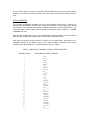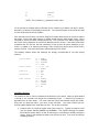
1
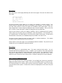
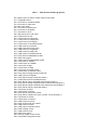
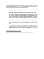
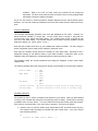
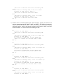
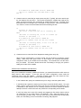
HomeVision Video Screens
Custom Solutions, Inc.
Copyright 1996 - 2004
Custom Solutions, Inc.
P.O. Box 33905
Indialantic, FL 32903
[email protected]
www.csi3.com
INTRODUCTION
HomeVision has a large number of built-in video screens for display on your TV. The user's manual
provides some information on how to use these; this file provides some additional data.
You can also create your own screens. Refer to the "How To" file to see how this is done.
BUILT-IN SCREENS
There are over 50 built-in screens. These screens are arranged in a video "menu" system. Using
your infrared remote, you can navigate through the screens to access all of HomeVision's functions.
To use a remote control, HomeVision and your remote must be configured as described in the IR
signal chapter of the user's manual. The rest of this discussion assumes you have already set this
up.
There are four ways to start displaying screens:
1) Pressing the "Channel Up" button on your configured remote.
2) Performing this command in your schedule:
Start Video Menu System
3) Performing these commands in your schedule:
Initialize For Internal Video Mode
Display Screen ##
4) If you selected the "prevent user from shutting video system off" option from the Controller
Settings Configuration Screen, the video system will always be on.
The first two methods both start the video screen system and display page 1 of the main menu.
The third method displays the selected screen. This is useful when you need to display a certain
screen and don't want to make the user have to navigate through the menu system to reach it.
Regardless of how you start the video system, you can always use your remote to navigate around.
MENU SYSTEM
The video screen menu system is a hierarchical system that allows you to access any function in
just a few key presses. There are four top-level menu pages. Each page has multiple menu entries
for moving to other screens or exiting the video system.
Menu Page 1 & 2
The first two main menu pages provide access to all of HomeVision's objects (X-10 modules,
variables, macros, input ports, scheduled events, etc.). They also allow you to view and change
some of the operating modes. All of the video screens accessed from these two menu pages are
fully functional without you having to do anything other than to load your schedule.
Menu Page 3
Main menu page 3 works slightly differently than the first two pages. There are five entries on this
menu page:
Security System
AC / Heat Zone 1
AC / Heat Zone 2
Event Log
Weather Conditions
The Security System screen allows you to control, you guessed it, a security system. This
screens works in conjunction with macros and variables in your schedule. For it to function, you
must first create macros to control your system and variables to hold system status. Then you
must configure the TV screen using the "Advanced" menu in the PC software. Then you can use
the TV screen to control the system. Details for setting this up are provided later.
There are two screens to control your Heating, Ventilation, and Air Conditioning (HVAC) systems.
These screens can be quickly set up as described in other documentation. For more power, you
can customize them in a similar fashion to how the security system screen works. This process is
discussed later in this article, and a detailed example is provided in the "How To" file.
The event log entry opens the event log screen, which is described elsewhere.
conditions screen is described at the end of this article.
The weather
All the entries on main menu page 3 can be individually enabled or disabled. They should only be
enabled after you've configured the respective systems.
Menu Page 4
Main menu page 4 is a user-definable menu. The screen contains 6 blank entries. You can
customize the text that's displayed on each. In addition, you can specify a macro that's performed
each time the user presses the corresponding button on their remote. You customize this screen
using the PC software (with the "Custom TV Menu" screen under the "Advanced" menu). This is
useful as a way to access your own custom screens. Details for setting this up are provided later.
VIDEO SCREEN NUMBERING SYSTEM
Each of the video screens has a unique ID number. You can display any screen by a command to
display the desired screen number. Table 1 lists all of the available screens in numerical order.
You'll notice that there is no obvious order to how the screens are numbered. Table 2 is an outline
of the hierarchical menu system. It shows which screens are displayed from each menu entry and
subentry.
Table 1
Video Screen Numbering System
#0 = Blank screen for users to create custom screens with
#1 = Configuration menu
#2 = List screen for scheduled events
#3 = List screen for input ports
#4 = Main menu page 1
#5 = List screen for output ports
#6 = List screen for IR signals
#7 = List screen for X-10
#8 = Help screen #1 for main menu
#9 = Control menu for X-10
#10 = Control menu for input ports
#11 = Control menu for output ports
#12 = Control menu for IR signals
#13 = Control menu for scheduled events
#14 = Help screen for input ports
#15 = Help screen #2 for main menu
#16 = Help screen for configuration
#17 = Help screen for output ports
#18 = Help screen for scheduled events
#19 = Entry field to enable/disable modes
#20 = Main menu page 2
#21 = Help screen for enable/disable modes
#22 = List screen for variables
#23 = Control menu for variables
#24 = List screen for flags
#25 = Control menu for flags
#26 = List screen for periodic events
#27 = Control menu for periodic events
#28 = Entry field to change periodic events rate
#29 = Help screen for IR signals
#30 = Entry field to change current time (Note 1)
#31 = Control time menu for scheduled events
#32 = Entry field to change scheduled event fixed time (Note 1)
#33 = Entry field to change scheduled event sunset/sunrise time (Note 1)
#34 = Entry field to change scheduled event random time interval (Note 1)
#35 = Entry field to change current date (Note 1)
#36 = List screen for timers
#37 = Control menu for timers
#38 = Entry field to change timer values
#39 = Entry field to change timer hours, minutes, or seconds (Note 1)
#40 = List screen for macros
#41 = Control menu for macros
#42 = Help screen for macros
#43 = Entry screen to set day of week
#44 = Help screen for timers
#45 = Help screen for periodic events
#46 = Status display screen
#47 = Help screen for X-10
#48 = Main menu page 3
#49 = Security system control screen
#50 = Thermostat configuration screen
#51 = HVAC zone 2 control screen
#52 = HVAC zone 1 control screen
#53 = HVAC thermostat schedule screen
#54 = Entry field to change HVAC temperature setting (Note 1)
#55 = Main menu page 4
#56 = DO NOT USE (FOR INTERNAL USE ONLY) (Note 1)
#57 = Caller ID Screen (Note 1)
#58 = Security system zones status
#59 = Weather conditions screen
#60 = Test screen for debugging add-on phone and serial port boards
Note 1:
Do not display these screens using the "Display video screen #" command. These
screens should only be accessed from the video menu system with an infrared remote.
Table 2
Video Menu System Hierarchy
MAIN MENU PAGE 1 (Screen #4)
Entry 1 = X-10 module list (Screen #7)
Menu to control X-10 module (Screen #9)
Help screen (Screen #47)
Entry 2 = Scheduled event list (Screen #2)
Menu to control event (Screen #13)
Help screen (Screen #18)
Menu to change event time (Screen #31)
Entry field to change fixed time (Screen #32)
Entry field to change sunset/sunrise time (Screen #33)
Entry field to change random time interval (Screen #34)
Entry 3 = Macro list (Screen #40)
Menu to control macro (Screen #41)
Help screen (Screen #42)
Entry 4 = Input port list (Screen #3)
Menu to control port (Screen #10)
Help screen (Screen #14)
Entry 5 = Output ports list (Screen #5)
Menu to control port (Screen #11)
Help screen (Screen #17)
Entry 6 = Help screen (Screen #8)
Help screen page 2 (Screen #15)
Entry 7 = Menu Page 2 (Screen #20)
Entry 8 = Exit (no screen)
MAIN MENU PAGE 2 (Screen #20)
Entry 1 = IR signal list (Screen #6)
Menu to control IR signal (Screen #12)
Help screen (Screen #29)
Entry 2 = Periodic event list (Screen #26)
Menu to control event (Screen #27)
Entry field to change event rate (Screen #28 )
Help screen (Screen #45)
Entry 3 = Flag list (Screen #24)
Menu to control flag (Screen #25)
Entry 4 = Variable list (Screen #22)
Menu to control variable (Screen #23)
Entry 5 = Timer list (Screen #36)
Menu to control timer (Screen #37)
Entry field to change timer values (Screen #38)
Entry field to change hours, minutes, or seconds (Screen #39)
Help screen (Screen #44)
Entry 6 = Configuration screen (Screen #1)
Entry field to change current time (Screen #30)
Entry field to change current date (Screen #35)
Entry field to change current day of week (Screen #43)
Entry field to enable/disable modes (Screen #19)
Help screen (Screen #21)
Status screen (Screen #46)
Thermostat configuration screen (Screen #50) (requires 2.5 PROM)
Help screen (Screen #16)
Entry 7 = Menu Page 3 (Screen #48)
Entry 8 = Exit (no screen)
MAIN MENU PAGE 3 (Screen #48)
Entry 1 = Security system control screen (Screen #49)
Entry 1 = Used to run security system macro; not a separate screen
Entry 2 = Used to run security system macro; not a separate screen
Entry 3 = Used to run security system macro; not a separate screen
Entry 4 = Used to run security system macro; not a separate screen
Entry 5 = Zones status screen (Screen #58)
Entry 7 = Main menu screen (Screen #48)
Entry 2 = AC & heating Zone 1 control screen (Screen #52)
Entry 1 = Used to run HVAC system macro; not a separate screen
Entry 2 = Used to run HVAC system macro; not a separate screen
Entry 3 = Used to run HVAC system macro; not a separate screen
Entry 4 = Used to run HVAC system macro; not a separate screen
Entry 5 = Thermostat schedule screen (Screen #53)
Entry 6 = Menu page 4 (Screen #48)
Entry 3 = AC & heating Zone 2 control screen (Screen #51)
Entry 1 = Used to run HVAC system macro; not a separate screen
Entry 2 = Used to run HVAC system macro; not a separate screen
Entry 3 = Used to run HVAC system macro; not a separate screen
Entry 4 = Used to run HVAC system macro; not a separate screen
Entry 5 = Thermostat schedule screen (Screen #53)
Entry 6 = Menu page 4 (Screen #48)
Entry 4 = Event log (Screen #56)
Entry 5 = Weather conditions screen (Screen #59)
Entry 6 = Unused
Entry 7 = Menu page 4 (Screen #55)
Entry 8 = Exit (no screen)
MAIN MENU PAGE 4 (Screen #55)
Entry 1 through 6 are user-definable
Entry 7 = Menu Page 1 (Screen #4)
Entry 8 = Exit (no screen)
USING THE CUSTOM MENU
Main menu page 4 is a user-definable menu. The screen contains 6 blank entries. You can
customize the text that's displayed in each. In addition, you can specify a macro that's performed
each time the user presses the corresponding button on their remote.
This menu page was designed for two primary purposes:
1) As a way for you to access your own custom screens. When the user presses one of the
six buttons, you could display a custom screen. When the user's done viewing the screen,
they can return to the menu system. This allows you to seamlessly integrate your screens
with the built-in screens.
2) To perform a macro whenever the user presses the corresponding button. Of course, the
user could also perform any macro by using the macro screen accessed through page 2 of
the main menu system. However, putting a few frequently used macros directly on menu
page 4 makes them easier to find and use.
The following procedure should be used to set up this menu screen:
1) Create a macro for each item you want in the menu (up to six). If you want to display a
custom screen, your macro must do it.
2) In the PC software, open the "Custom TV Menu" screen under the "Advanced" menu.
3) For each entry you want displayed on main menu page 4:
A) Enable the menu item by checking the check box (unchecked entries will display
"Unused").
B) Enter the text to be displayed next to the menu number (up to 22 characters)
C) Select the macro you want to perform when the user presses the corresponding remote
button.
4) Click OK.
5) Load the schedule into the controller.
That's all there is to it. You might want to first test this out by creating a simple macro (perhaps
flashing the controller's "User" LED). Once you're comfortable with how it works, you might try
creating your owns screens and accessing them from here.
USING MENU PAGE 3
Page 3 of the TV screen menu can access special screens to control security and HVAC systems
and display weather data. This section describes how to set these up.
There are several important points to note about using the security and HVAC screens:
-
These screens use the values of your variables to determine the status to display on the TV
screen. To function, your schedule must:
o
o
o
-
Create the variables.
Tell HomeVision which variables are used to hold which status.
Change the variables as your system changes. For example, if you're using a variable
to hold the current temperature reading from your thermostat, you should periodically
read it and update the variable.
When the user is viewing one of these screens and presses a button on their remote, the
controller automatically executes a macro. To function, your schedule must:
o
o
Create the macros. The macros should perform whatever you want to happen when the
user presses the button. Typically, you would cycle a status variable to the next
setting. You would also usually send a command to your security system or
thermostat to change to the new setting.
Tell HomeVision which macro should be used for each remote button.
SECURITY SYSTEM CONTROL SCREEN
Main menu page 3 can access the security system control screen. This screen can provide you
status and control of your security system. Of course, to do this HomeVision must be able to
communicate with your security system. There are several different methods that may work,
depending on your system:
-
Serial interface. If your security system has a serial (RS-232) interface, you may be able
to connect it directly to HomeVision's serial port. However, only one device can be
connected to this port at a time. You can only connect the security system after you've
loaded the schedule into HomeVision from the PC and disconnected the PC.
-
Input and output ports. Most security systems provide relay or voltage outputs that
indicate the current status. You may be able to connect these to HomeVision's input
ports. Many systems also allow you to arm and disarm them by opening and closing a
relay. You could do this by connecting a relay to the Port A relay driver outputs and
interfacing the relay to the security system.
-
X-10 interface. Some security systems can communicate via X-10 signals. Also, if your
system has direct inputs or outputs available, you may be able to interface to them with X10 Powerflash or Universal modules.
These devices can then communicate with
HomeVision via X-10 signals to monitor and control your system.
The security system control screen that is displayed on your TV is shown below.
SECURITY SYSTEM
1-System Mode : ARMED
2-Alarm Status: OK
3-Interior
: ON
4-Perimeter
: ON
Active Zones: 16
5-Display Zones 1-8
6-Display Zones 9-16
7-Main Menu
ENTER MENU NUMBER
Here's how this screen works:
•
Four variables that you define are used to hold the status of the security system. The
controller uses the values of these variables to determine what to display next to entries 1-4
on the screen.
•
When you press buttons 1-4 on your remote control, the controller will execute a
corresponding macro that you created. This macro should cycle the security system
between the desired states. In this way, you can control your system with your remote,
with your macros actually doing the work.
•
When you press buttons 5 or 6, the controller automatically displays another screen
showing the status of each zone. For each zone, you must define a variable to hold the
current state. The controller uses the values of these variables to determine what to
display next to the zone's status.
As you can see, these TV screens provide the interface between the user and the security system.
However, you must still create the variables and macros that actually hold the status and do the
work.
STATUS VARIABLES
The controller automatically generates most of the text displayed on this screen. However, the
status values are handled in a unique way. On this screen, items 1 through 4 display the security
system status. Your schedule must include a variable to hold each of the four status values. The
controller will then use the values of these variables to decide what text to display (i.e., ARMED,
UNARMED, OK, etc.).
How does the controller know which of your variables will contain the status? You tell it using the
security system configuration screen under the PC software's "Advanced" menu.
How does the controller decide what text to display for each status field? HomeVision has a
predefined meaning for the different values of your status variables. HomeVision looks up the
variable's value, then displays the corresponding text as shown in Table 3.
TABLE 3 MAPPING OF VARIABLE VALUES TO DISPLAYED TEXT
VARIABLE VALUE
0
1
2
3
4
5
6
7
8
9
10
11
12
13
14
15
16
17
18
19
20
21
22
23
24
25
26
27
28
TEXT DISPLAYED ON TV SCREEN
OFF__
ON___
AUTO_
COOL_
HEAT_
OK___
ERROR
ALARM
NA___
HIGH_
LOW__
NO___
YES__
OPENED
CLOSED
ERROR_
SECURE
OFF____
ON_____
ERROR__
ALARM__
ARMED__
UNARMED
UNUSED_
BYPASS_
SECURE_
OPENED_
CLOSED_
OK_____
29
30
31
INSTANT
FIRE___
_______
NOTE: The underscore (_) represents a blank space
You should use the variable values in this table in your schedule if you want to use this TV screen.
Otherwise, the status will be displayed incorrectly. You'll notice that many of the entries are used
for other purposes than security systems.
Also note that each text entry is a specific length and contains blank spaces at the end to make it
that length. Each of the states used for a variable should have the same length of text. This is
necessary to ensure the status is displayed properly. This is because if the status changes while
the screen is being displayed, the new text is displayed over the old text. If the new text has fewer
characters than the old text, the last character(s) of the old text will remain displayed on the
screen. In addition, if an extra-long text string is used, it might wrap around at the end of the line
onto the next line. This would cause some visible flickering on the screen.
The following variable values and meanings are strongly recommended for use with security
systems:
System Mode:
Alarm Status:
Interior:
Perimeter:
Zone Status:
21
22
29
30
5
7
0
1
0
1
24
25
26
27
28
= ARMED
= UNARMED
= INSTANT
= FIRE
or 28 = OK
= ALARM
= OFF
= ON
= OFF
= ON
= BYPASS
= SECURE
= OPENED
= CLOSED
= OK
CONTROL MACROS
The numbers on the TV screen correspond to the buttons on your remote. When you press buttons
1 through 4, the controller will change the corresponding mode. It does this by executing a
separate macro for each button. You must create the macros that actually change the modes.
Every time you press the button, your macro is then executed. Your macro should cycle the
security system between each mode that you want. This is done as follows:
1) Create a macro to control the system mode (menu entry #1). Typically, this macro would
cycle the system between ARMED and UNARMED. This requires changing the variable
that holds the system status, as well as executing the command(s) to actually change the
system. Refer to the example schedule to see how this is done. Your macro should look
something like this:
If
Variable #1 (Security System Mode) = 21
;The value 21 indicates the system is currently ARMED
Then
;The system is currently ARMED, so DISARM it:
Variable #1 (Security System Mode) = 22
;The value 22 indicates the system is UNARMED
X-10 Module A1 (Security System Control) FORCE OFF
;This X-10 command disarms the security system
Else
;The system is currently UNARMED, so ARM it:
Variable #1 (Security System Mode) = 21
;The value 21 indicates the system is ARMED
X-10 Module A1 (Security System Control) FORCE ON
;This X-10 command arms the security system
End If
2) Menu entry #2 is used to reset the alarm if it is going off (an alarm condition). For many
security systems, this is done by simply disarming it. If yours works this way, you don't
really need to use this menu entry. Instead, menu entry #1 can be used to disarm it and
you can skip this macro. However, some systems require a separate command to reset it
if it's going off. To accomplish this, you should create a macro that sends the necessary
command(s).
3) Create a macro to turn the system's INTERIOR mode on and off (menu entry #3), if your
system has such a capability (if not, skip this macro). Your macro should look something
like this:
If
Variable #2 (Interior Mode) = 0
;The value 0 indicates the interior is currently OFF
Then
;The interior is currently OFF, so turn it ON:
Variable #2 (Interior Mode) = 1
;The value 1 indicates the interior is ON
X-10 Module A2 (Interior Control) FORCE ON
;This X-10 command turns the interior ON
Else
;The interior is currently ON, so turn it OFF:
Variable #2 (Interior Mode) = 0
;The value 0 indicates the interior is OFF
X-10 Module A2 (Interior Control) FORCE OFF
;This X-10 command turns the interior OFF
End If
4) Create a macro to turn the system's PERIMETER mode on and off (menu entry #4), if your
system has such a capability (if not, skip this macro). This would be similar to controlling
the INTERIOR mode, as discussed above.
SPECIFYING VARIABLES AND MACROS
After you've created the necessary variables and macros, you must tell HomeVision which ones are
being used for which purpose. To do this, open the security system configuration screen under the
"Advanced" menu of the PC software. Enter the following information:
•
In the text box at the top of the screen, enter the number of zones in your system. The
software currently supports up to 16 zones.
•
In the Variables tab, specify the variables that you're using to hold the system status.
These are the variables that correspond to the first 4 entries displayed on the TV screen.
You must also specify the variable that holds the status of the first system zone. Note that
your zone status variables must be grouped together and consecutively numbered. For
example, if you have 10 zones, they might be held in variables 25 through 34, with zone 1
being in 25, zone 2 in 26, etc.. If you may be adding more zones in the future, you should
define the variables now so you have enough room to group them together.
•
In the Macros tab, specify the macros you're using to control the security system. You
must select a macro in each of the 4 list boxes, even if you're not using some of the them.
This is admittedly a little awkward, but is necessary because the current software will
always attempt to execute a macro when the user presses the corresponding remote
button.
If you're not using one or more of the entries, we suggest you first create a macro and put
no commands in it (you might name it "Do Nothing"). Then, select this macro for any
menu entry that you aren't using. This way, each time the user presses the corresponding
button, the "Do Nothing" macro is executed, but nothing really happens.
USING THE SECURITY CONTROL SCREENS
Load your schedule into the controller and you're ready to control your security system.
HVAC SYSTEM CONTROL SCREEN
Main menu page 3 can access the HVAC system control screen. This screen can provide you
status and control of two separate zones.
What follows is a description of how to use your own macros to control the HVAC system, which
most users will not need to do. If you wish to do this, you should read this first, then refer to the
"How To" file installed in the HomeVision directory, which details a complete, customized
thermostat control system using the RCS TX-10B bidirectional thermostat.
The main HVAC control screen that is displayed on your TV is shown below. The same screen is
used to display both zones 1 and 2 (but only one at a time).
AC/HEAT CONTROL <Zone 1>
1-Control Mode: RUN
2-HVAC Mode
: COOL
3-Fan Mode
: AUTO
4-Current Setting: 75
Current Temp
: 76
5-View/Edit Schedule
6-Refresh Settings Now
7-Main Menu
ENTER MENU NUMBER
Here's how this screen works if you're using your own macros to control it:
•
Five variables that you define are used to hold the status of the HVAC system. The
controller uses the values of these variables to determine what to display next to entries 1-4
and for the current temperature.
•
When you press buttons 1-4 on your remote control, the controller will execute a
corresponding macro that you created. This macro should cycle the HVAC system
between the desired states or change the temperature setting. In this way, you can control
your system with your remote, with your macros actually doing the work.
•
When you press button 6, the controller automatically displays another screen showing a
thermostat schedule. This screen allows you to program a schedule for your thermostat. It
has the following features:
-
Separate schedules can be set for each zone.
Each zone can have a separate schedule for the "Cool" mode, "Heat" mode, and
"Auto" mode.
Each schedule consists of eight times and three different daily programs. The daily
programs are for:
o
o
o
-
Monday through Friday
Saturday
Sunday
The schedule can be turned on and off at any time. It is controlled by the first entry
("Control Mode") on the HVAC control screen. When in the "Auto" (or Run) mode, the
controller will change the thermostat temperature settings as indicated by the
schedule. When in the "Off" (or Hold) mode, the controller will not change the
thermostat. The OFF mode works the same as "HOLD" does on many programmable
thermostats, leaving the setting unchanged.
As you can see, these TV screens provide the interface between the user and the HVAC system.
However, you must still create the variables and macros that actually hold the status and do the
work.
STATUS VARIABLES
The controller automatically generates most of the text displayed on this screen. However, the
status values are handled in a unique way. On this screen, items 1 through 4, along with the
"Current Temp" entry, display the system status. Your schedule must include a variable to hold
each of the five status values. The controller will then use the values of these variables to decide
what text to display (i.e., AUTO, COOL, 75, etc.).
How does the controller know which of your variables will contain the status? You tell it using the
HVAC configuration screen under the PC software's "Advanced" menu.
How does the controller decide what text to display for each status field? HomeVision has a
predefined meaning for the different values of your status variables. HomeVision looks up the
variable's value, then displays the corresponding text as shown previously in Table 3.
The variables holding the current temperature and setting are displayed as their actual values
instead of text.
The following variable values and meanings are strongly recommended for use with HVAC systems:
Control Mode:
HVAC Mode:
Fan Mode:
Current Setting:
Current Temp:
0
2
0
2
3
4
1
2
- OFF
- AUTO
- OFF
- AUTO
- COOL
- HEAT
- ON
- AUTO
Variable should be actual value of temp setting
Variable should be actual value of current temp
CONTROL MACROS
The numbers on the TV screen correspond to the buttons on your remote. When you press buttons
1 through 4, the controller will change the corresponding mode or setting. It does this by executing
a separate macro for each button. You must create the macros that actually make the changes.
Every time you press the button, your macro is then executed. This is done as follows:
1) Create a macro to cycle the HVAC control mode between OFF and AUTO (menu entry #1).
This requires simply changing the variable that holds control mode. Your macro should
look something like this:
If
Variable #5 (HVAC Control Mode) = 0
;The value 0 indicates the mode is currently OFF
Then
;The mode is currently OFF, so set it to AUTO:
Variable #5 (HVAC Control Mode) = 2
;The value 2 indicates the mode is AUTO
Else
;The mode is currently AUTO, so set it to OFF:
Variable #5 (HVAC Control Mode) = 0
;The value 0 indicates the mode is OFF
End If
2) Create a macro to control the HVAC mode (menu entry #2). Typically, this macro would
cycle the system between OFF, HEAT, COOL, and AUTO. This requires changing the
variable that holds the HVAC status, as well as executing the command(s) to actually
change the system. Refer to the example schedule to see how this is done for the RCS
TX-10 thermostat. Your macro should look something like this:
If
Variable #6 (HVAC Mode) = 0
;The value 0 indicates the mode is currently OFF
Then
;The mode is currently OFF, so set it to HEAT (4):
Variable #6 (HVAC Mode) = 4
X-10 Module A2 (HVAC Mode Control) FORCE OFF
;This X-10 command sets the HVAC mode to HEAT
End If
If
Variable #6 (HVAC Mode) = 4
;The value 4 indicates the mode is currently HEAT
Then
;The mode is currently HEAT, so set it to COOL (3):
Variable #6 (HVAC Mode) = 3
X-10 Module A3 (HVAC Mode Control) FORCE OFF
;This X-10 command sets the HVAC mode to COOL
End If
If
Variable #6 (HVAC Mode) = 3
;The value 3 indicates the mode is currently COOL
Then
;The mode is currently COOL, so set it to AUTO (2):
Variable #6 (HVAC Mode) = 2
X-10 Module A4 (HVAC Mode Control) FORCE OFF
;This X-10 command sets the HVAC mode to AUTO
End If
If
Variable #6 (HVAC Mode) = 2
;The value 2 indicates the mode is currently AUTO
Then
;The mode is currently AUTO, so set it to OFF (0):
Variable #6 (HVAC Mode) = 0
X-10 Module A1 (HVAC Mode Control) FORCE OFF
;This X-10 command sets the HVAC mode to OFF
End If
3) Create a macro to control the fan mode (menu entry #3). Typically, this macro would cycle
the fan between ON and AUTO. This requires changing the variable that holds the fan
status, as well as executing the command(s) to actually change the fan. The RCS TX-10
thermostat does not currently have a command to control the fan. Other thermostats do.
Your macro to control such thermostat should look something like this:
If
Variable #7 (Fan Mode) = 1
;The value 1 indicates the fan is currently ON
Then
;The mode is currently ON, so set it to AUTO (2):
Variable #7 (Fan Mode) = 2
X-10 Module F1 (Fan Control) FORCE ON
;This X-10 command could set the fan to AUTO
Else
;The mode is currently AUTO, so set it to ON (1):
Variable #7 (Fan Mode) = 1
X-10 Module F1 (Fan Control) FORCE OFF
;This X-10 command could set the fan to ON
End If
4) Create a macro to control the HVAC temperature setting (menu entry #4).
When the user presses button 4 on their remote, they will be able to change the current
setting. When they finish press "Enter" on their remote, the controller automatically
changes the value of your variable to the new setting. The controller then runs the macro
that you created. This macro should execute the command(s) to change your system's
setting to the value of this variable.
SPECIFYING VARIABLES AND MACROS
After you've created the necessary variables and macros, you must tell HomeVision which ones are
being used for which purpose. To do this, open the HVAC configuration screen under the
"Advanced" menu of the PC software. Check the "Enable screen" box, then select the "Use
custom macros and variables" option. Enter the following information:
•
In the Variables tab, specify the variables that you're using to hold the system status.
•
In the Macros tab, specify the macros you're using to control the HVAC system. You must
select a macro in each of the 5 list boxes, even if you're not using some of the them. This
is admittedly a little awkward, but is necessary because the current software will always
attempt to execute a macro when the user presses the corresponding remote button.
If you're not using one or more of the entries, we suggest you first create a macro and put
no commands in it (you might name it "Do Nothing"). Then, select this macro for any
menu entry that you aren't using. This way, each time the user presses the corresponding
button, the "Do Nothing" macro is executed, but nothing really happens.
USING THE HVAC CONTROL SCREENS
Load your schedule into the controller and you're ready to control your HVAC system.
WEATHER CONDITIONS SCREEN
Main menu page 3 can access the weather conditions screen. Currently, data to be displayed on
the screen can only come from the serial interface. Refer to the serial interface protocol
documentation for details.