1
NAGRA 4.2
PORTABLE ANALOGUE AUDIO
TAPE RECORDER
INSTRUCTION MANUAL *
(KSA code No. 20 04 004 151)
Kudelski S.A.
NAGRA Tape Recorder Manufacturer
CH–1033 Cheseaux / SWITZERLAND
phone (021) 731 21 21
telex 459 302 nagr ch
telefax (021) 731 21 55
February 1991 Edition
Copyright reserved for all countries
Orginally printed in Switzerland
*this is an exclusive digital reprint and may only be used by Hunter College Students
1.1
INTRODUCTION
The Nagra 4.2 was introduced originally in 1971. It is a portable 6.35 mm (1/4") mono analogue audio tape
recorder designed for high quality recording having radio, cinema, and television applications.
Many mechanical and electronic modifications have been made to the machine since its release, to adapt it
according to modern day requirements. Despite all these modifications, the machine remains remarkably similar to the original.
The Nagra 4.2 can be delivered in two different versions both of which are available in either NAB or CCIR equalization. These versions are:
NQ–LSP
Non pilot
NQS–L
Pilot
Each version has three speeds: 38 cm/s. 19 cm/s and 9.5 cm/s (15, 7 1/2 and 3 3/4 ips) and has either the
NAB or the CCIR standard.
The Nagra 4.2 is a mono recorder recording full track audio on 6.35 mm tape, and the Neopilot
synchronization system.
The audio inputs may be used with either the two internal microphone preamplifiers (switchable between
Dynamic, T power and Phantom power depending on the microphone preamplifier which is fitted) or as a line
input, via the QCE cable.
The Nagra 4.2 also contains a switchable limiter, a built–in loudspeaker, and an internal reference generator for
line up, and calibration purposes.
Optionally the machine may be fitted with the NEOPILOT pilot option.
The machine may also be powered from either an external supply ATN–3 or internal batteries.
The 4.2 may also be used with the QGB 10" real adaptor, to allow the use of larger reels for longer recording
and playback.
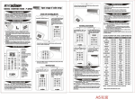
23
24 21 19 26 27
28 29 20
30 11 31 5 34 22
32
25
10
33
17
18 14
12
13
7
9
8
6 1 3 2
4
16
15
1. TAPE / DIRECT SWITCH (line and phones)
20. SPEED AND EQUALIZATION SELECTOR
2. TAPE / DIRECT (snap switch)
21. MOBILE TAPE GUIDE
3. POWER SELECTION SWITCH (external/batteries)
22. PINCH ROLLER
23. REWIND AND FAST FORWARD SWITCH
4. MAIN FUNCTION SELECTOR (six position
rotary)
5. PINCHWHEEL LIFTER (stop + test
only)
24. TAPE REELS
25. TENSION ROLLERS
26. ERASE HEAD
6. LEVEL CONTROL mic input 2
27. STROBOSCOPE ROLLER
7. LEVEL CONTROL mic input 1
28. RECORDING HEAD
8. REFERENCE OSCILLATOR (push button)
29. PILOT HEAD
9. LINE & PLAYBACK POTENTIOMETER
30. PLAYBACK HEAD
10. MANUAL/AUTOMATIC SELECTOR
31. CAPSTAN SHAFT
11. LID CATCH
12. MODULOMETER MODE SELECTION
SWITCH
32. PINCHWHEEL AND TAPE GUIDE CONTROL LEVER
33. TAPE TENSION ROLLER (OR TIMER)
13. FILTER SWITCH
34. TAKE–UP REEL
14. MODULOMETER
15. PILOT INDICATOR
16. SPEED AND POWER INDICATOR
17. HEADPHONES OUTPUT
18. HEADPHONES VOLUME CONTROL
19. REEL FIXING NUT
1.2 CONTROLS: DESCRIPTION AND USE
FRONT PANEL
1. TAPE / DIRECT SWITCH (line and phones)
When in "TAPE" position, the signal is reproduced directly from the tape.
When in "DIRECT" position, there are two possibilities:
a) When recording, the signal is available before arriving on the tape.
b) When playing back, the signal may be adjusted by means of the level control and corrected by filter switch (13).
NOTE: When the machine is in "TEST" position, the output is the direct signal regardless of this switch’s position.
2. TAPE / DIRECT (snap switch)
This switch affects the meter in the same way that the previous switch affects the output. Thus when it is held
to the left, the meter will display the "OFF TAPE" signal otherwise it displays the "DIRECT" (EE) signal.
3. POWER SELECTION SWITCH (external / batteries)
The Nagra 4.2 may be powered by either internal batteries or by an external source which may be selected using
this switch. See also the Power Supply section of this manual.
4. MAIN FUNCTION SELECTOR (six position rotary)
STOP
Stops the machine completely from any function, and will slightly move the pinch wheel away
from the capstan to prevent a "flat" being caused on the pinch roller. In this mode no circuits
are powered.
TEST
Will power all circuits and allow level adjustment by means of level controls (6), (7) and (9). In
this mode the motor is not powered. All indications of the modulometer will be of the "DIRECT"
input, irrespective of the position of tape / direct switch (1).
RECORD
Is the first of the two "RECORD" positions and corresponds to "RECORD WITH LIMITER" where
the recording level is limited to + 4 dB. This level remains constant when the input level is
between + 4 dB and + 10 dB. Thus in this position tape saturation cannot occur and distortion is avoided.
RECORD
(no limiter)
The limiter is inactivated in this position so that recordings that should be saturated can be
made.(e.g. gun shots or explosions).
PLAYBACK
Is the first of the two playback possibilities and corresponds to playback of the tape to the headphones and line output only.
PLAYBACK
(with
speaker)
This position is exactly as above, only it allows monitoring via the internal loudspeaker at the same
time. This is also the only position of the main function selector that permits the "FAST FORWARD" function to be performed.
5. PINCHWHEEL LIFTER (stop + test only)
6. LEVEL CONTROL mic Input 2
7. LEVEL CONTROL mic Input 1
These are the main level controls for the two microphone inputs.
8. REFERENCE OSCILLATOR (push button)
On the lower edge of the front panel, between the line and playback potentiometer and the mic 2 potentiometer. is the reference generator push button. When this button is pressed, a composite 1.1 kHz signal with a 10
kHz 9th harmonic at a level of approximately –8 dB is injected into the "DIRECT" chain of the recorder.
The modulometer will show –8 dB. It is useful to record a short burst of this signal at the beginning of each reel
of tape so as to enable the level of the playback chain to be accurately calibrated before the real recording is
made. This also permits adjustment of the record head azimuth in the field without test equipment. At this point
the subject of print–through should be mentioned. After a certain period of time, a recording may be copied (at
reduced level) onto adjacent turns of a tape on a reel. This produces a perceptible echo during the silences proceeding or following a strong sound.
It is thus recommended to leave a pause of two or three turns of tape after recording the "REF" signal.
9. LINE & PLAYBACK POTENTIOMETER
This potentiometer is used to adjust the line input level when using the machine to record a signal, from
line input (41).
10. MANUAL/AUTOMATIC SELECTOR
This switch allows selection of the sensitivity adjustment of the microphone inputs. In the "MANUAL" position
the sensitivity is adjusted by means of potentiometers (6) and (7). In "AUTOMATIC" position I this gives ALC
(automatic level control) to mic input I only and in position 2 to both mic inputs.
11. LID CATCH
12. MODULOMETER MODE SELECTION SWITCH
This is an eleven position rotary switch allowing different information to be displayed on the modulometer.
Each position is described below
X
Position not used.
RX
Indicates the level of the RF signal picked up by the antenna of a QRR receiver (if fitted)
(see note).
SYNCH
This indicates the phase shift between the pilot playback signal from the tape and the reference signal. Synchronism is correct when the needle is stationary.
PILOT PLAYBACK
This indicates the level of the pilot signal played back from the tape.
PILOT FREQ
This indicates on the + 4 to –4% scale of the modulometer, the frequency deviation as
determined by the QFM frequency meter circuit (if fitted), between the pilot signal being
recorded or played back and the 50/60 Hz reference.
LEVEL
The modulometer will indicate the level of the direct or of the recorded signal on the
decibel scale.
BATT. RESERVE
Indicated on the lower scale, the bold line shows the supply voltage reserve; the lower limit
at the extreme left of the bold line represents 11 V.
VOLT/CELL
This is a battery check indicating on the V/CELL scale of the meter the Volts per cell
of the batteries.
COMPRESSION
Compression reading in decibels on the ALC compression scale when switch (10) is in the
"AUTOMATIC" position.
MOT
This measures the motor current– Maximum deviation = 250 mA.
BIAS
This indicates the record bias level on the V/CELL scale.
NOTE :
The QRT I QRR radio transmitter and receiver accessories are no longer manufactured.
13. FILTER SWITCH
This is a six position rotary switch, allowing different filter possibilities to be switched in or out.
LFA 2
LFA 1
FLAT
HP 1
HP1 + LFA1
HP2
Low frequency attenuation, –8 dB at 50 Hz.
Low frequency attenuation, –4 dB at 50 Hz.
The machine has a linear response.
High pass filter. –10 dB at 50 Hz.
Combination of high pass and low frequency attenuation, –14 dB at 50 Hz and –3
dB at 400 Hz.
High pass filter, –20 dB at 50 Hz.
14. MODULOMETER
This meter is the visual indication of many functions and levels of the machine. The modulometer displays information according to the position of mode selector switch (12).
The modulometer has 4 scales
1.
2.
3.
4.
Recording level in dB
Frequency deviation in %
Battery voltage (volts / cell)
Compression
15. PILOT INDICATOR
If the machine is fitted with the pilot system, this rotary "SASS" type indicator shows a white segment when the
pilot signal frequency is correct.
NOTE:
This only indicates the presence of a correct signal being fed to, or coming from the
head, and does not guarantee correct recording of the signal. This should be checked by
switching the modulometer to "PILOT" playback (this does not function in the "RECORD"
mode).
16. SPEED AND POWER INDICATOR
This rotary "SASS" type indicator gives a quick visual indication that the machine is functioning correctly and
will indicate a white segment when this is the case. It will turn black whenever any of the following conditions
occur:
–
The Power supply voltage (batteries or external) becomes insufficient for correct operation of
the machine.
–
The motor current reaches its maximum limit, in this case voltage and speed stabilizer circuit
A22 requires the motor to run faster, but this is not possible because the automatic current
limiter circuit has been activated. (If this occurs during normal operation, then contact your
nearest Nagra agent.)
–
"WOW and FLUTTER" is out of tolerance. (Contact Nagra agent).
Thus, when a white segment is indicated, the operator can be absolutely sure that the power supply is sufficient,
that the motor current is correct, and that the tape speed is within tolerance.
17. HEADPHONES OUTPUT
This 1/4" jack type socket (type 297) is the headphones output socket accepting headphones with an impedance of anything from 50 Ω to 600 Ω.
18. HEADPHONES VOLUME CONTROL
This small potentiometer is adjustable using a screwdriver and adjusts the level fed to headphones output
connector (17).
Position 1 is the minimum and position 6 is the maximum.
19. REEL FIXING NUT
TAPE DECK
20. SPEED AND EQUALIZATION SELECTOR
This is a six position rotary switch permitting the selection of the speed and equalization of the 4.2 in both
record and playback.
Possible settings are:
3 3/4
7 1/2
15
ips
ips
ips
(9.525 cm/s)
(19.05 cm/s)
(38.10 cm/s)
For each of these speed selections there are two possible positions labelled I and II; these correspond to
different tape types.
For best quality recordings, the 15 ips speed is recommended.
For normal recordings, the 7 1/2 ips speed is available. The 3 3/4 ips speed is available for those cases where
the length of recording time of the tape is more critical than the actual quality of the recording.
21. MOBILE TAPE GUIDE
22. PINCH ROLLER
23. REWIND AND FAST FORWARD SWITCH
REWIND
is possible with main selector (4) in any position other than "STOP", assuming pinch roller
lever (32) is in the fully open position.
FAST FORWARD
is possible only with main function selector (4) in the "PLAYBACK– (with loudspeaker)
position and pinch roller lever (32) fully engaged.
The central position of this switch is "OFF" and this is the position that the switch should be in whenever the
machine is not required to spool. Keeping it in this position will prevent accidental spooling of the tape when
opening the pinch roller gate or playing back a recorded tape through the internal loudspeaker.
24. & 34. TAPE REELS
The 4.2 can be used with reels up to a maximum diameter of 5" (127 mm) with the plexi–glass lid closed, or up
to 7" (178 mm) with the lid open. However. it the QSET option is fitted to the machine the 7" (178 mm) reels
my be used with the lid closed.
If it is necessary to use reels of up to l0" (254 mm), then the QGB large reel adapter may be used.
25. & 33. TENSION ROLLERS
These two rollers keep the tape tension constant and ensure correct tape handling and positioning. During normal use neither of these two rollers should be at either end of its travel. If this is the case refer to the Mechanical
Calibration section of the service manual.
The two rollers can be replaced by either the QTIM or QLEN tape measuring rollers. The QTIM is supplied in
the place of the take–up reel tension roller as standard equipment. QLEN instead of QTIM is optional. (To be
stated when ordering).
26. ERASE HEAD
This is a full track erase head.
27. STROBOSCOPE ROLLER
This roller comes in two versions : 50 Hz (CCIR machines) and 60 Hz (NAB machines). Using this roller, it is
possible to check that the machine is running at the correct speed, either in record or playback. This works at
all speeds and uses the stroboscopic effect whenever a mains powered lamp is shone upon it. When at the correct speed, the bars on the roller should appear stationary.
28. RECORDING HEAD
Audio recording head.
29. PILOT HEAD
Neopilot head used for both recording and playback of pilot signals.
30. PLAYBACK HEAD
Audio playback head.
31. CAPSTAN SHAFT
Tape main drive.
32. PINCHWHEEL AND TAPE GUIDE CONTROL LEVER
This lever engages and disengages the tape from the heads and motor capstan shaft. It also moves the
stroboscope roller and mobile tape guide in and out, to allow easy loading of the tape.
When it is in the open position, rapid rewinding is possible. (This lever should never be left in the open position
for long periods of time as this may cause a "FLAT" on the capstan shaft "0" ring).
33. TAPE TENSION ROLLER (OR TIMER) (see 25)
34. TAKE–UP REEL (see 24)
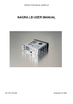
Positions 36 to 49 see CONNECTORS
1.3 CONNECTOR
38
36
37 39
41 40
42 43 49
36. MIKE 2 Input
NAB
CCIR
1
= Input signal Ground
2+3
= Balanced signal Input
37. MIKE 1 input
Identical to No 36 above.
NOTE: The microphone inputs are convertible into symmetrical and floating line inputs by installing, in place of
the microphone preamplifiers, preamplifiers type QPM–6 and using the corresponding potentiometer to
control the input level.
38. RX
Antenna input for QRR receiver.
39. ACC (accessories)
1. No connection.
2. Ground
3. Line input, current drive. Minimum source impedance 47KΩ.
Current for obtaining 0 dB at maximum sensitivity = 3.73 µA.
4. Tape speed correction signal input.
5. No connection.
6. –10 V stabilized voltage.
40. MIXER
For connection to external mixing console. (connector type; T 3478 corresponding plug T 3475/1).
1. Input with fixed sensitivity, 560 mV to obtain 0 dB, input impedance 9 kΩ (2.5 Vpp to obtain + 4 dB).
2. –10 V stabilized voltage, maximum current 50 mA. Noise level <
5 µV rms.
3. Direct amplifier output, minimum load impedance 10 kΩ, output
voltage 560 mV at 0 dB. This is a monitoring signal to be fed back
to the mixer.
4. Unstabilized negative supply voltage. Available in all positions of the
main function selector. Current drawn should not exceed 2 A as this
may blow the internal fuse if working with internal batteries.
5. Playback amplifier output minimum load impedance 100 kΩ, output voltage 560 mV at 0 dB.
6. Motor stop control terminal (connect to –10 V to stop motor).
Operational in all modes except "REWIND". It is not recommended
to use this remote method in "REC" as this will magnetize the
recording head and reduce performance.
7. Ground (chassis).
41. LINE INPUT
Banana jack line input connector. Input impedance 100 kΩ, input voltage to obtain 0 dB on maximum sensitivity 370 mV. Maximum voltage, up to 150 V. This is the value supported by the input resistance, but it is
not recommended to exceed 10 V as crosstalk might be produced. Up to 150 V has been foreseen to allow for
connection to a sound distribution system at 100 V nominal.
42. VOL
Loudspeaker volume control.
43. MICROPHONE INPUT SELECTOR
This is a four position microphone input selector
DYN 200
=
+48
=
+12
=
T
=
Dynamic microphone impedance 200 Ω 0.2 mV / µbar
(2mV/pa) sensitivity.
Condenser microphone, 1.5 mV/µbar (l5mV/pa) sensitivity
+ 48 V phantom powering.
Condenser microphone, 1.5 mV/µbar (15mV/pa) sensitivity
+ 12 V phantom powering.
Condenser microphone, 1.5 mV/µbar (15mV/pa) sensitivity
+ 12 V T powering.
49 51 50
47
48 45
46 44
50
44. PILOT AND CLAPPER INPUTS:
1. Ground
2. CLAPPER: Clapper oscillator control input (control voltage + 4 to
+ 14 V) or switching on of QRR receiver by connecting to ground.
3. XTAL: Internal crystal pilot generator output, 50/60 Hz.
4. PILOT IN: Pilot signal input, impedance 5 kΩ. Input level 0.5 –
25 V.
45. LINE OUTPUT
The line output of the Nagra 4.2 is on the right–hand side of the recorder. The load impedance should be
equal to or greater than 600 Ω. When the "LINE AND PHONES" switch is in the position "TAPE", the line output voltage is 4.4 V into 600 Ω while playing back a tape recorded at 0 dB. The Nagra 4.2 can record at a
level 4 dB higher than this, thus the maximum line output voltage will be 7 V. Unloaded, these voltages will
be 10% greater. The line output uses two 4 mm banana sockets. It is the secondary of a transformer and is
floating. A banana socket connected to the chassis is available beside the line output sockets.
46. GROUND (banana socket)
47. LOUDSPEAKER
48. POWER PACK 6 pole connector for external power supply and pilot signal output.
1.
2.
3.
4.
5.
– BATT: Negative pole of battery compartment.
+ BATT: Positive pole of battery compartment.
PILOT PLAYBACK: Pilot playback output.
SPEED CORRECTION: Tape speed correction input.
EXTERNAL –12 to –30: Input for external power Supply –12 to
–30 V negative pole.
6. –10 R: –10 V stabilized voltage output during record, I max
100 mA
49. FIXTURE FOR CARRYING STRAP/HANDLE
50. CASE FIXING SCREW
51. PLATE SHOWING RECORDING AND PLAYBACK EQUALIZATION.
1.4
POWER SUPPLY
All models of the Nagra 4.2 may be powered either by an external power supply (ATN–3) or alternatively by internal batteries. The 4.2 will accept voltages ranging from –11 V to –30 V with peaks of up to –35 V. The batteries are placed in the bottom of the machine and the polarity is marked inside the battery compartment. It is
opened by turning the two fasteners with a screwdriver or a small coin. All the batteries MUST be orientated in
the same direction as indicated on the base of the battery compartment.
The Nagra 4.2 houses twelve "D" type 1.5 V cells having a maximum diameter of 33.5 mm and a length of
between 59.5 and 62.5 mm. It is important to remember that corrosive material can leak out of flat batteries,
causing severe damage to the recorder, and therefore it is recommended not to leave batteries in the machine
during periods of storage.
If leakage occurs as a result of leaving flat batteries in the machine, then wash the affected area with fresh
water. The machine will suffer much less from the water than the electrolyte from the batteries. The external
supply is fed into the machine via connector marked "POWER PACK" (48) on the right side of the machine.
Rechargeable batteries may also be used and can be charged using the ATN–3C (order no 14376) which
includes the charger circuitry.
The 4.2 will function when the power is as low as 12 V (at 15 ips – 38 cm/s) and down to as low as 10.5 V at
the lower speeds. (These figures correspond to a machine in perfect condition and working at room temperature).
When using an external supply, selector switch (3) must be in the "EXTERNAL" position. It must be in the "BATTERIES" position when internal batteries are in use. It is not necessary to remove the batteries when working
with an external supply (and vice versa).
Danger of Reversed Polarization
A reversed polarization of the power supply (negative to ground) could cause serious damage to the unprotected
early versions of the Nagra 4.2. Since then, three 2.5 A fuses have been added in the battery compartment which
protect the Nagra when batteries or accumulators are used. A fourth fuse mounted in parallel in the wiring further protects the machine when powered by batteries as well as when powered by an external supply.
Measuring Battery Condition and Power Supply Voltage
Battery Reserve
When the Meter Switch is put into the "BATT. RESERVE" position the meter will indicate the difference between
the power voltage available and the power which the Nagra needs. Often the two voltages will fluctuate. The
device will take into consideration the lowest instantaneous voltage and memorize this. This detail is important,
for the average voltage of a power supply can be sufficient but momentary drops in the voltage can happen and
drop lower than the required minimum.
New batteries will give about 18 V whereas the Nagra can be powered by up to 30 V. This explains why, with new
batteries, the needle of the meter will only indicate about 40% full scale, when it is switched to "BATT. RESERVE".
Volt / Cell
The meter switch in this position works as a simple voltmeter. The centre scale is graduated from 0 to 1.6 V, it
indicates 1/12 of the total voltage or the average voltage of 1 cell.
The position Volt/Cell is essentially designed to monitor the voltage of some accumulators which would be damaged it they were allowed to discharge below a certain value. This value is 1 V /Cell for certain manganese dioxide alkaline accumulators.
It is also possible to monitor the external power supply voltage. When in the "BATT. RESERVE" position, if the
indication is that the Nagra is not receiving sufficient voltage, but the Volt/Cell indicates that the power supply
voltage is correct, this means that the Nagra requires an abnormally high voltage. Under these conditions the
Motor and motor collector should be examined.
Measuring the Motor Current
The meter will measure the motor Current when the meter switch is in the position "MOT". There is no corresponding scale on the meter but the "VOLT/CELL" scale can be used.
Full scale deflection corresponds to a motor current of approximately 250 mA. In "NO LOAD" running, i.e. without tape and with the pinchwheel separated from the capstan (but not in the rewind mode), the needle should
indicate between 0.2 and 0.3 V. If this value is exceeded, see chapter 4 pp. 34/35.
External Power Supply
On the right side of the machine there is a 6 pin Tuchel– type T 3403 connector marked "POWER PACK". The
corresponding plug is the T 3400/1.
The connections are as follows :
pin
pin
pin
pin
pin
pin
1
2
3
4
5
6
=
=
=
=
=
=
Battery negative
Chassis (positive)
Pilot playback output
Speed correction signal input
Negative external supply
–10 V stabilized output.
1.5
OPERATION
On the right side of the front panel is the main function selector, which determines the mode in which the Nagra
works. By putting it into the position "TEST", all the circuits are powered, but not the motor. If the meter switch,
on the upper right side of the modulometer, is switched to the "BATT. RESERVE" position, the needle of the modulometer indicates that the Nagra is powered. (if this is not the case see Power Supply in this manual).
With fresh batteries, the needle will not advance to more than half–way up the scale. It only reaches the
extreme right of the scale with an external power supply.
After checking the power supply, put the meter switch to the "LEVEL" position (recording or modulation level).
A microphone can receive sounds of a very variable intensity. The tape must be recorded as fully as possible,
but without the high frequencies passing a level called the "saturation" level. The modulometer indicates the
level of modulation. The needle can deflect up to the mark "Max" on the right of the scale, but should not pass
this limit. If the needle is deflected less, the recording will be of a lower level.
The sensitivity, i.e. the level of recording for a given sound, can be controlled either manually or automatically.
The choice is made by means of the "AUTOMATIC/MANUAL" switch on the upper left of the front panel. In the
position "MANUAL" the level can be controlled by means of potentiometers (6) and (7). In the position "AUTOMATIC" the level is controlled by an Automatic Level Controller. The modulometer deflects with respect to the
incoming signal without reaching the extreme right end of the scale.
Tape Speed and Standard Selection
The Nagra 4.2 is capable of running at three different speeds which can be selected by means of "SPEED AND
EQUALIZATION" selector (20) on the top deck of the recorder between the two spools.
The speeds available are
3 3/4 ips (9.525 cm/s)
7 1/2 ips (19.05 cm/s)
15 ips (38.10 cm/s)
Each position of this selector automatically selects the correct equalization of the machine according to the
chosen speed. There are two different positions available for each speed and they are marked "I" and "II" which
represent Standard and Low noise respectively.
For adjustments of equalization and checking of tape speed refer to the 4.2 service manual.
NOTE: The Nagra 4.2 is only equipped with one recording bias oscillator and it is therefore only possible to
bias the recorder for one specific tape type at any one time. However, it is possible to optimize the
equalization in the second position (LN) for a different tape.
Loading a Tape on the Recorder
Select "STOP", then release the tape path from the heads, guides and capstan shaft by pulling lever (32) forward, until it comes to a complete stop. Remove the spool retaining nuts and place a reel of tape on the left
turntable, with the loose end of the tape coming from the left side of the spool. Pass the tape around the left
guide roller and across in front of the heads, and around the right guide roller. Attach the end of the tape to the
empty spool on the right turntable. Replace the two spool retaining nuts, and close lever (32) until it reaches its
original position, thus putting the tape into contact with the heads.
NOTE:
It is important to lower the head–shield before loading a tape, otherwise the tape may pass behind it,
and thus not be in contact with any of the heads. When the tape has been loaded and lever (32) has
been restored to its original position, the shield may be lifted in front of the heads.
Recording
The Nagra 4.2 can make a recording using either microphones or a "DIRECT" line input signal.
Recording with Microphones
When using microphones, connect them to the two XLR type connectors on the left side of the recorder. If the
QPAU–T/QPU–T microphone preamplifiers are installed in the recorder, check that the switches corresponding
to each of the microphone inputs are in the correct position for the type of microphone being used. The possible selections are T–power, + 12 V and + 48 V phantom, powering or 200 Ω dynamic.
The level of the signal coming from the microphones may be observed by putting the machine into the "TEST"
position and switching modulmeter switch (12) to the "LEVEL" position. The gain may now be adjusted using
potentiometers (6) and (7) on the front panel.
Turn the main function selector to either of the two "RECORD" positions, depending upon whether the limiter is
required or not. Observe the modulometer to see that the levels remain correct throughout the recording. The
modulometer indicates in both "RECORD" modes the "DIRECT" signal. It is possible to show the "OFF TAPE" signal during the recording by moving the "LINE AND PHONES" snap switch to the left.
Depending on the position of "TAPE / DIRECT" switch (1) it is possible to monitor either the input signal, or the
"OFF TAPE" signal on the headphones output during the recording. This is possible because the Nagra 4.2 has
separate heads for recording and playback (moving this switch will not affect the recording).
Recording a Line Signal
Recording a line input signal rather than a microphone signal is very similar to working with microphones. Set
microphone potentiometers (6) and (7) to their fully anti–clockwise position (this is to prevent any noise to be
amplified by the high gain microphone preamplifiers. and recorded on the tape).
Connect the line input signal to line input connector (41) on the left side of the recorder. Set main function
selector (4) to the "TEST" position and adjust the level of the incoming signal on the modulometer by means of
potentiometer (9) marked "LINE AND PLAYBACK". Finally switch the main function selector to one of the
two "RECORD" positions to start the recording. When the recording is completed, select "STOP".
Fast Forward / Rewind
To rewind a tape put the main function selector in the "STOP" position, and open the pinchwheel gate by using
operating lever (32) then select "TEST" and rewind the tape by means of toggle switch (23) located on the top
left front comer of the top deck.
When the tape is fully rewound always place operating lever (32) back in the fully closed position (this will prevent a "flat" portion being made on the capstan "0" ring).
To wind a tape fast forward use switch (23) as for rewind. However, it is not necessary to open the pinch roller
gate. The "FAST FORWARD" position of the toggle switch is only active when the main function selector is in the
"PLAYBACK" (with loudspeaker) position. This is done to prevent accidental winding of the tape during recording.
While winding the tape fast forward, the audio on the tape will be heard through the internal loudspeaker. To
avoid damage to the loudspeaker, use volume control (42) to decrease the level.
Playing Back a Recorded Tape
Rewind the tape as explained above, then set main function selector (4) to one of the two possible "PLAYBACK"
positions (either with, or without loudspeaker). The signal from the tape is now available on line output banana
output connectors (45/46) on the right side of the recorder. If line and phones switch (1) is in the "TAPE" position, the signal is fed directly to the line outputs with no possibility for adjustment. However, if it is in the
"DIRECT" position then the output may be adjusted with the "LINE AND PLAYBACK" potentiometer.
The frequency response may also be modified using "FILTER" switch (13).
Working with Headphones
If headphones are to be used, they can be plugged into jack socket (17).
The level of the headphones may be adjusted using potentiometer (18). In record, the signals can be monitored
either off tape or directly, depending on the position of the line and phones switch.
NOTE:
When the machine is in the "TEST" position, the headphones output is always fed with the "DIRECT"
signal.
The headphones output will accept a 1/4" stereo Jack connector and can be used with headphones having an
impedance from 50 Ω to 600 Ω.
During playback, the headphones may be used for monitoring. In the position "TAPE" the signal coming from the
tape can be heard. In the position "DIRECT" a mixing of the signals coming from the microphones and from the
tape can be heard. The mixing of these signals can be controlled by means of the potentiometers "MIKE 1",
"MIKE 2" and "LINE AND PLAYBACK".
To listen to the recording on an external amplifier/loudspeaker installation, connect it to the Line Output on the
right of the recorder. This output receives the same signal as is transmitted to the headphones. Loudspeaker signals should not be allowed to feed a microphone. Under these conditions, the signal passes from the loudspeaker
to the microphone which retransmits it, producing a howling known as the Larsen effect (acoustic feedback).
To avoid this effect, the "LINE AND PHONES" switch should be placed in the position "TAPE" or the potentiometers "MIKE 1" and "MIKE 2" turned down.
To playback in the headphones or to an external installation, the position "PLAYBACK" of the Main Function
Selector should be chosen. The internal loudspeaker is thus disconnected.
Precautions
The pinch wheel is automatically disengaged in the position "STOP" of the Main Function Selector. This enables
the Nagra to be stored with the Pinch Wheel and Tape Guido Control Lever in the closed position. If this lever is
in the disengaged position, the lid of the recorder cannot be closed.
Do not store the recorder with the Main Function Selector in any position other than "STOP", as this will cause
a "flat" to be formed on the pinchwheel and this will cause Wow and Flutter problems during future uses. To avoid
the accidental discharge of the batteries, put the "POWER" switch into "EXTERNAL", thereby disconnecting the
internal batteries (if installed).
If the recorder has to be stored for a long period of time, remove the batteries, as a corrosive liquid can leak from
discharged batteries.
Direct and Tape Chains
General
Signals coming from the microphone(s), line and mixer inputs, once they are amplified, fiftered, controlled and
mixed, form the "DIRECT" signal which will be recorded on the tape.
The signal played back from the tape gives, after amplification and equalization, the "TAPE" signal. During
recording, the "TAPE" signal is that which has already been recorded on the tape, and therefore is not that
which is being recorded.
The modulometer measures the level of the "DIRECT" signal. It is operational even in the absence of a tape. On
the other hand. there will be no "TAPE" signal in this case.
When the Nagra is in playback, the level control potentiometer "LINE AND PLAYBACK" is used to adjust the
"TAPE" signal. The "DIRECT" signal may therefore be made up of the input signals, plus the playback signal. This
allows for example, the superimposition of a commentary to the signal being played back from a tape. On
the other hand, the "TAPE" signal will always be exclusively the playback signal from the tape.
The line output amplifier, which also feeds the headphones, can be connected either to the "TAPE" signal or to
the "DIRECT" signal, the choice being made by the "LINE AND PHONES" switch on the front panel. The loudspeaker amplifier is only fed from the "TAPE" signal. Acoustic feedback, therefore cannot be produced, even if
the microphones are in service, unless, of course, this takes place from the headphones.
The Line and Phones snap switch allows meter readings of the playback signal while recording. It always snaps
back into the "DIRECT" position.
Audio Inputs
The Nagra 4.2 has 4 inputs:
–
2
microphone inputs
–
1
asymmetrical line input transformable into a 3rd microphone input by means of an external preamplifier
–
1
mixer input at fixed level
Manual Level Control
When using manual level control, adjust the position of the microphone potentiometers in such a way that the
loudest sounds to be recorded do not exceed the maximum level. The potentiometers corresponding to the
unused inputs should be kept in their anti–clockwise position.
The active potentiometers can be equally used to give a compression, by increasing the sensitivity during the soft
passages, and vice verse.
Limiter
The Nagra 4.2 is equipped with a safety limiter which instantaneously reduces the gain of the recording amplifier when the signal exceeds the maximum level providing that the "RECORD" with limiter position of the Main
Function Selector has been selected. This limiting evidently causes distortion, but it is less objectionable than
that caused by saturation of the tape. Normally, the limiter will only be brought into action when accidents occur.
It is possible that, in the middle of a dialogue, for example, a short but high power sound exceeding the maximum level can occur. Under these conditions it is preferable to saturate rather than to limit because the saturation will be practically unnoticeable due to the short duration of the sound. Moreover, the limiter requires a
certain recovery time before the normal sensitivity of the chain is re–established. This sensitivity variation can
allect the ambient sound and can be a greater nuisance than saturation by a brief sound. To avoid this phenomenon, it is necessary to reduce the recovery time of the limiter. Detailed instructions as to how this can be
done will be sent on request. The limiter can be switched off by setting the Main Function selector to position
"RECORD – NO LIMITER". This may be advantageous for certain recordings, e.g. gunshots, explosions, where
tape saturation is desired.
Automatic Level Control (ALC)
The Nagra 4.2 is fitted with an Automatic Level Control. It replaces the manual potentiometer when the selector
switch placed on the left of the meter is on the position "AUTOMATIC". In the position "1–AUTOMATIC", only
microphone No 1 has its sensitivity controlled automatically. Microphone No 2 is controlled by its respective potentiometer. In "2–AUTOMATIC", both microphone inputs are controlled by the ALC circuit. The operation of the ALC
is complex. It is useful to place the meter switch in the position "COMPRESSION" as the needle will indicate by
how much the sensitivity of the amplifier chain has been reduced. The extreme left position corresponds to a maximum gain; the extreme right to a reduction of gain or compression of approximately 30 dB.
When a signal, whose amplitude is sufficient for the maximum recording level to be exceeded, arrives from the
microphone, the Automatic Level Control will instantaneously reduce the gain to avoid over–modulation (similar
to the limiter). If the signal is short, the Automatic Level Control concludes that it is accidental, and forgets it
rapidly, i.e. it returns to its previous sensitivity. On the other hand. a longer signal is considered useful.
The sensitivity is therefore memorized and maintained. This avoids the increase of background sound level
between words. It can happen, however, that an interfering signal is long and thus results in a long sensitivity
reduction. To avoid this, the Automatic Level Control has a circuit of rapid recovery which enters into action if
the level remains at less than –10 dB for about 1 1/2 seconds. Therefore, if a long and loud noise upsets the
recording, the recorder can be reset to its normal sensitivity by keeping quiet for 1 1/2 seconds.
Experience has shown that the Automatic Level Control allows an absolutely automatic recording to be made for
reporting interviews etc. and of a quality which is difficult to attain with manual control.
Measurement of Signal Level
The Nagra 4.2 is equipped with a device for measuring the signal level. Normally, this is a modulometer, but a
VU–meter is available on special request.
The meter is connected to the "DIRECT" signal. During recording it measures this level. If the line amplifier is
connected to the "DIRECT" Signal ("LINE AND PHONES" switch in "DIRECT"), the measurement will be that of
the signal sent along the line. On the other hand, if the "LINE AND PHONES" switch is in "TAPE", the level sent
along the line will be independent of the "DIRECT" signal and will consequently not be measured. In any case, the
level of this signal cannot be altered. A signal recorded at nominal level will give a line signal of nominal level.
CHAPTER 2: PILOT
2.1
INTRODUCTION
The Nagra 4.2 (NQ–L version) is equipped with a Neopilot system. This system developed by KSA, records a synchronization signal simultaneously with the audio, of 50 Hz (60 Hz in NTSC countries). Two signals are recorded in phase opposition so as to avoid any interference with the audio replay chain. The pilot signal serves as a
speed reference to ensure that when the tape is replayed, it is always replayed at the same speed at which it was
recorded. The pilot signal can either be supplied from an external source (a film camera for example) or can be
generated by an optional internal crystal generator (QGX–3).
If a recording is made with a pilot version of the Nagra 4.2 it is later possible, during playback, to lock the speed
of the Nagra by means of the pilot synchronizer (QSLI) to an external reference signal. This means that providing the "start" point of the recording is known for both the film camera and the Nagra then the two can remain
in perfect synchronization throughout the tape.
To obtain a film with a synchronous sound it is necessary to keep the image and the sound continually slaved to
one another. The acceptable tolerance is in the region of 40 m Sec.
2.2
OPERATION
Recording a Pilot Signal
A pilot signal can be recorded when recording either a line input signal or when using microphones.
Recording the Internal Crystal
For the 4.2 to record its own pilot signal the QGX–3 crystal generator must be fitted to the machine. This circuit
is located on the left side of the battery compartment inside the machine. It has two operating frequencies: 50
or 60 Hz. Check by means of the switches on the circuit that the correct frequency has been selected. Then
switch the main function selector to the "TEST" position. Pilot indicator (15) on the top right side of the front
panel should show a white segment. If this is not the case then check that the pilot crystal shorting plug is located in pilot socket (44).
This jumper plug is like a blank screw with the letters "XTAL" marked on it. If this is installed and the rotary indicator does not show a white segment then check that the machine is correctly powered and that power selector
(3) is in the correct position with respect to the supplied source. If this is all correct but the indicator remains
black then consult your nearest Nagra agent.
Once the indicator shows a white segment, the pilot signal will be recorded automatically. No further manipulation of the pilot system is needed.
Recording an External Pilot Signal
Remove the crystal shorting plug in connector (44) and feed pilot input socket (44) by means of the QCP cable.
The other end of the cable must be connected to the source (either an ATN–3, camera ... ). Check that the external pilot signal is present by switching the machine to the "TEST" position as above. While making a recording
the cable must always be left connected.
Make the recording as above.
Synchronizing a Recorded Tape
Check that the machine is fitted with the QSLI synchronizer circuit. This circuit is located on the right side of the
battery compartment inside the machine. The circuit faces downwards, and has its front right corner cut away.
Feed pilot input connector (44) with the reference signal either from the pilot out socket on the ATN–3 (for synchronization to mains) or from the machine to which the 4.2 is to be synchronized. Turn the main function selector to the "PLAYBACK WITH LOUDSPEAKER" position, and after a short period (typically 1 1/2 secs) pilot indicator 15) should once again show a white segment. Check the level of the pilot signal from the tape by switching modulometer switch (12) to the position "PILOT PLAYBACK". The needle should deflect about half way. If
the modulometer selector is switched to the position "SYNCH" the meter will indicate the deviation between the
external pilot reference and the pilot signal from the tape.
Frequency Meter (optional accessory QFM)
This device measures the frequency of the pilot signal. If the meter switch is in the PILOT FREQUENCY position, the meter will indicate the frequency. The scale is from +4% on the left side to –4% on the right. The accuracy is about ±O.1% on the centre of the scale. In addition, the frequency meter circuit gives a warning if the
frequency is more than 5% out from its nominal value. It this is the case, the rotary "Pilot" indicator turns black.
The QFM exists in two versions for 50 Hz and 60 Hz (QFM 50 and QFM 60).
Quartz Crystal Pilot Generator (optional accessory QGX–3)
This accessory is designed for synchronous filming without cable between the camera and the Nagra. It supplies
a signal whose frequency is 50 Hz ± 0.001%, and is very stable within a wide temperature range.
A dummy plug is supplied with the generator. The solution of using a dummy piug rather than a switch, has been
adopted in order to reduce the risk of human error. The QGX–3 is switchable and gives a 50 Hz or 60 Hz signal.
Pilot Indicator
This device is found on the upper right of the front panel. It shows a white cross when the Nagra is in operation
and it a pilot signal of sufficient amplitude is provided, and if there is no "Alarm" signal in the pilot system. The
"Alarm" signal will appear and turn the indicator black if the following conditions occur:
a)
if the frequency of the pilot signal is incorrect (on condition that the QFM frequency meter circuit is installed)
b)
if the pilot signal does not reach the pilot head (on condition that the QSLI synchronizer circuit
is installed)
This is indicated in the position "TEST" of the main function selector. When the Nagra is in playback, this indicator will only show a white segment when a pilot signal is being played back from the tape and another pilot
signal is being fed from outside. It one of these two signals is missing, the indicator will remain back. This is
very important when using the QSLI.
Internal Synchronizer (optional accessory QSLI)
This device has two functions:
a) It measures the amplitude of the playback pilot signal on the tape. With the meter switch in the
position "PILOT PLAYBACK" the meter indicates the amplitude. The normal value should be
between 1 and 2 V on the lower middle scale.
b) It can modify the tape speed of the Nagra in order to render the playback pilot signal synchronous
with a pilot signal coming in on the PILOT socket. For this speed correction to take place, the Nagra
must be switched to "LOUDSPEAKER PLAYBACK" and the "PILOT" indicator should show a white
cross. The white cross is only shown if the external pilot reference signal is correct and a pilot signal is played back from the tape.
When meter switch (12) is in the "SYNCH" position, the meter is connected to the QSLI, and shows the difference of phase between the external pilot signal and the playback pilot signal from the tape. Thus if the signals
do not have exactly the same frequency and phase the needle will oscillate. This can be seen on PLAYBACK
(without the loudspeaker). One complete oscillation left, right, left, every 2 seconds corresponds to a speed error
of 1% which can be corrected by the QSLI.
By putting the main function selector in the "LOUDSPEAKER PLAYBACK" position the QLSI is switched on,
and the needle should be stationary. If it continues to oscillate, then the frequency exceeds the synchronizing
capacity of the QSLI.
If the Nagra is equipped with frequency meter circuit QFM, and the needle is stationary and it the pilot indicator shows a white cross, synchronization is practically certain.
There is one exception, however, it the playback frequency from the tape is grossly incorrect (e.g. 100 Hz instead
of 50), the needle will not be able to follow the beat and will remain stationary in the centre of the dial.
If this is suspected, switch to "PLAYBACK". The needle should oscillate. If need be, upset the tape speed by blocking the left side tension roller momentarily. If the needle remains in the centre, the recorded pilot signal is incorrect.
The speed varier QSV–2 is very useful in these cases. In attempting to adjust the speed (on slaved playback) the
QSLI has to adjust itself in order to prevent the speed varier from operating. The needle of the meter will show
this adjustment and will prove that synchronization is correct.
Speed Varier QSV–2
This is an external accessory for the Nagra 4.2. It is plugged into the ACC socket (39) on the left side of the
recorder. It enables the speed to be varied manually up to ± 12% The QSV–2 is used for the following applications:
a) To transfer a tape whose pilot signal originated from a camera the speed of which was out of tolerance.
The QSLI synchronizer allows the automatic correction of speed errors up to ± 2%. It is not
unknown for cameras to have a speed error greater than this tolerance. The speed varier allows the
offsetting at the average speed which will then be corrected by the synchronizer in the normal
manner. Naturally, under these conditions the tone of the sound will be altered, but this is
inevitable.
b) Transfer of a tape whose pilot signal is interrupted. A very convenient method of indicating the start
marks (or end of takes) as well as the take identification, is by short interruptions of the pilot signal. During these interruptions. the slaving between the Nagra 4.2 and the film recorder is suppressed. It is important that the speed change during the suppression is not brutal, otherwise audible wow will be heard. To avoid this, it is sufficient to make approximate correction with the aid of
the speed varier and to allow the synchronizer to make a final adjustment to ensure the slaving.
This can be done as follows:
Method A
1. Play back the tape to be transferred without slaving. When using the QSLI internal synchronizer,
put the Nagra into PLAYBACK without loudspeaker.
2. Adjust the speed with the aid of the speed varier QSV–2 in such a manner that the playback
pilot signal and the mains are approximately synchronized. The needle of the Nagra meter
(switch on "SYNC") will not swing.
3. Rewind the tape and make the transfer in the usual manner. Under these conditions, the speed correction achieved by the synchronizer will be very small.
Method B
Make the transfer in the classic manner and adjust the speed varier so that the needle (in the position "SYNC") remains at the centre of the scale (QSLI). This method is less precise but, it is sufficient
in practice. It should be noted, however, that the interruptions of the pilot signal happen at the beginning of a sequence, and it is almost always necessary to make a trial playback, adjust the speed,
rewind and then make the transfer.
Use of Speed Varier While Filming on Playback
While filming on playback, it is possible that the camera may run at an incorrect speed. It will therefore be necessary to adjust the camera, if possible, to avoid any change in the tone of the final sound. If this is not possible, correction can be made with the speed varier (see above).
Recording of Facsimile and Similar Signals
A Nagra equipped with a Quartz Crystal Pilot Generator and a QSLI Synchronizer can reproduce, on playback,
frequencies with a precision of the order of 0.001%, as any slipping or stretching of the tape is automatically
compensated for. This applies to average frequencies for, inevitably, mechanical tolerances and longitudinal
vibrations of the tape will affect the instantaneous speed (wow and flutter).
Experience has shown that this precision is more than sufficient for the recording and reproduction of facsimile
signals. Other telemetering applications are, of course possible.
Pilot Playback Using a Nagra 4.2 L not Equipped with QSLI Synchronizer
Output impedance: 47kΩ ± 20%
Load impedance: from zero to infinity
Output voltage from tape recorded on Nagra 4.2 L: 330 mV ± 3 dB
Pilot Playback Made by Nagra 4.2 L Fitted with QSLI Synchronizer
Output impedance: 10 kΩ ± 20%
Load impedance: from zero to infinity
Output voltage from tape recorded on Nagra 4.2 L: 0.85 V nominal ±3 dB.
The Nagra 4.2 fitted with a QSLI can be used to measure the playback pilot signal. 0.85 V corresponds to a
meter deflection of 1 V on the scale calibrated from 0 to 2 V and normally used to measure the voltage per cell
of the batteries 1.7 V corresponds to full scale deflection.
Pilot Connectors
On the Nagra 4.2, the pilot playback signal is to be found on Power Pack connector (48) which is a 6 pin Tuchel
socket located on the right side of the recorder.
Pin No 2 is connected to the chassis and the output pilot signal is connected to pin No 3.