1
Capacities:
INSTRUCnONS
FISHER DRY BATH INCUBATORS
11-718
11-718-2
11-718-4
11-718-6
11-718-8
Catalog Nos.
P o w e r Requirements:
11-718
11-718-2
11-718-4
11-718-8
11-718-8
11-718
11=718-2
11-718-4
11-718-6
11-718-8
1 Block
2 Blocks
3 Blocks
4 Blocks
6 Blocks
115V, 50/60 Hz,
115V, 50/60 Hz,
115V, 50/60 Hz,
115V, 60/60 Hz,
116V, 50/60 Hz,
90 Watts
180 Watts
270 Watts
360 Watts
540 Watts
Fisher Dry Bath Incubators provide controlled heat for a
wide variety of clinical and general chemistry applications.
They operate through a temperature range from sligjttly
over ambient to 130 C. The variotis models can
accommodate 1, 2, 3, 4, or 6 dry blocks. Each imit is
controlled by two adjustable thermostats, one for
operation up to about 60 C, and the other for up to 130
C. A fully-insulated pad-type heating element is bonded
direct^ to the entire underside of the dry block support
plate to provide even heat distribution. The support
plate is made from altmiinum for rapid heat transfer.
Unpacking
Each model is designed to be used with any of ei|^t
different accessory dry blocks. (See the Accessories
Section for a listing, of catalog numbers). Blocks are
made from solid aluminum with a black anodized finish.
Each block is marked so that every well can be identified.
Dry blocks can handle a variety of tubes from 1.5 ml
microcentrifuge tubes to 25 imn diameter tubes. All of
these accessory dry blocks are interchangeable.
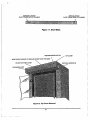
These Dry Bath Incubators are shipped in a sin^e carton,
complete^ assembled. Each is supplied with this mantial,
a warranty card, and a Dry Block Handle (for handling
or moving dry blocks). The warranty card should be
completed and retumed as soon as possible. In cases
where shipping damage is observed, keep the unit and
carton intact, including the packaging materials, and file
a claim with the final carrier.
Typical applications for these dry baths include
incubation, ctilture inactivations, enzyme reactions,
melting and boiling points, and many other procedures
that require controUed heat.
Note; Because of the wide variety of applications and
sample block designs, dry blocks are not included with
dry baths. The user must select and order the blocks
that best suit the ptirticular application.
Perfomiance Characteristics
OPERATION
Temperature Range:
Efich dry bath is equipped with two temperature controls
(thermostats), a selector switch, and a red-lensed lamp
which indicates heater operation. The lamp comes on
when the controlling thermostat, as selected by the
switch, closes to supply power to the heater. Once the
dry bath reaches thennal equilibrium, the (ycling of the
lamp, and the heater, should continue on a regular, basis.
In case of a malfunction, such as a heater failure or
thermostat stuck in the closed position, the lamp will
remain OIL Should the thermostat fail with the contacts
open, the l i ^ t wiU remain off.
Slightly Above
Ambient to 130 C
Note: Tolerances on temperature ranges are
approximately -5 to +10 C. Maximtun attainable
temperature may exceed 140 C.
Uniformity: *
-t- or - 0.5 C
*Variation, at a given time, of a sample temperature
from the average of all sample temperattu'es within a
dry block (at 37C). Temperature variation between
blocks may exceed this spec.
Physical Data:
11-718
11-718-2
11-718-4
11-718-6
11-718-8
9in X 8in X 3.6in
9inX8inX3.5in
9in X l l i n X 3.5in
12.5inX8.5inX3.5in
12.6in X l l i n X 3.5in
4.6 lbs
4.7 lbs
5.8 lbs
8.1 lbs
7.4 lbs ,
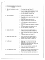
1. Place the imit on a flat, level surface, in an area free
ofdrails and temperature changes. (Note; Drafts and
ambient temperature changes will adversely affect
temperatture constancy and uniformity.)
i
>
2. Make sure that bath cavity is free of foreign matter,
then place empty dry block(s) into bath cavity.
3. Connect unit to an appropriate, grotmded power
source as specified on the unit's data plate.
4. Insert an immersion type thermometer, graduated to
the desired temperature range, into the thermometer
well in the diy block. Note; For more precise
measurements, the thermometer can be placed into
the sample tube or a similar tube adjacent to the
sample tube.
5. Set the three-position switch at the appropriate
setting:
liow" setting for ambient to 60 C
"Hii^" setting for 60C to 130 C
6. Ac^ust the appropriate temperature control to a
setting that approximates the desired temperature.
The following can be used as a general guideline. On
the Low temperature control a setting of "0" will be
ambient, "6" or ' T about 40 C, and "10" about 60 C
On the H i ^ temperature control a setting of "0" will
heat samples to about 50 C, "5" will heat to about 90
C, and "10" about 130 C.
7. As the dry bath is heating, monitor the temperature
reading on the thermometer and observe the indicator
lamp. Ifthe thermometer reading exceeds the desired
temperature, reduce the temperature control setting.
When the lamp cycles on and off at regular intervals
(or "flickers"), the unit has reached equilibrium. Ifthe
dry bath is not at the desired temperature, ac|jiist the
temperature control in the appropriate direction.
8. Once the dry bath has stabilized at the desired
temperature, samples may be inserted into the blocks.
9. Use the Dry Block Handle to remove blocks.
Be sure that the Dry Block Handle is securely engaged
with the block before lifting it from the bath. CAUTION:
-
Be s u r e dry bath is connected to only
grounded power sources of the appropriate
voltage.
Never heat samples beyond safe levels.
T i ^ t l y capped sample tubes may burst when
heated.
Use t h e Dry Block Handle to move the dry
blocks.
T u m t h e Selector Switch to the Off position
and unplug unit w h e n not in use.
MAINTENANCE
These dry baths require no periodic maintenance other
than routine cleaning with mild cleaning products. Be
sure units are tmplugged prior to cleaning. Never use
abrasives or harsh chemicals to clean units. Never
immerse tinits in liqtiids or pour liqtiids onto the dry
block support plate.
SERVICE
It is recommended that dry baths be serviced only fay
those qualified in instrument maintenance. Service is
available at any ofthe Instnmient Service District Offices
located throu^out the country. If you need service or
service information, please contact the office nearest to
yoiL The representatives there can issue a retum
authorization number, if necessary. Emergency, on- site
service calls are not cowered \mder the warranty.
Unit Disassembly
WARNING: Unplug unit prior to disassembly.
1. Loosen set screws euid remove temperattire control
knobs.
2. Tum tmit upside-down and remove four screws.
3. Remove base by first lifting at rear, then moving
forward to dear temperature control stems.
4. Note the routing of wires and the location of insulation
so that the unit can be property re-assembled.
5. Carefulty remove insulation.
Thermostat Replacement
1. (Optional) Remove screws that attach Heater Base
Assembty to the Top Cover Assembly.
2. Observe wiring connections, then remove two wires
connected to appropriate thermostat.
3. Remove fastener holding thermostat in place, then
remove thermostat.
4. Connect wires to new thermostat and install.
5. Re-attach Heater Base Assembly if it has been
removed.
6. Position base onto uiut and check alignment of
thermostat shaft with center of hole in front of base.
Remove base and reposition thermostat as required,
then tighten securely.
Heater Replacement
FOR BEST RESULTS:
- Use Dry Bath Incubators in an area with a constant
ambient temperature and no drafts.
- All samples should be placed in identical tubes, filled
to equal levels no higher than top of block. All siunple
tubes should be placed in identical blocks.
1. The beater is permanently bonded to the dry block
support plate, and can only be replaced as a preassembled unit. This assembly is called a Heater Base
Assembly.
2. Remove the fasteners which attach the thermostats to
the dry block support plate.
3. Remove the fasteners that attach the dry block
support plate to the dry bath top cover assembly.
4. Locate and remove the splices at the end ofthe heater
leads.
l-r\-
5. Cormect the new heater leads, making sure that the
coimections are secure and properly insulated.
6. Attach the new dry block support plate and
thermostats (see Thermostat Replacement section).
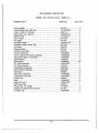
ACCESSORIES
Item
Capacity
Dry Block, 24 tubes, 1.5ml
Dry Block, 30 tubes, 6mm diameter
Dry Block, 20 tubes, 10mm diameter
Dry Block, 20 tubes, 13mm diameter
Dry Block, 12 tubes, 16mm diameter
Dry Block, 8 tubes, 20mm diameter
Dry Block, 6 tubes, 25mm diameter
Dry Block, Combination
' 6 tubes, 6mm diameter
5 tubes, 13mm diameter
3 tubes, 25mm diameter
Selector Switch o r Indicator Lamp Replacement
1. Note wiring coimections of device to be replaced, then
remove wires.
2. Squeeze tabs that hold device in place, then push out
through front of base.
3. Install new device into appropriate hole in base.
4 Reconnect wires.
Cat. no.
11-718-9
11-718-10
11-718-12
11-718-14
11-718-16
11-718-18
11-718-20
11-718-22
Re-Assembly
1. Position insulation over heater.
2. Make sure that wires lu-e routed so as not to come in
contact with heater.
3. Properly position base, checking alignment of
thermostats as in Thermostat Replacement section.
4. Fasten base to top cover, and replace knobs.
P a r t No. 83315
Instructions for Dry Bath Incubators
Rev. A. (12/91)
Replacement P a r t s
Item
Thermostat, Low Temp
Thermostat, H i ^ Temp
Selector Switch
Indicator Lamp
Dry Block Handle
Heater Base Assembly for
Heater Base Assembly for
Heater Base Assembly for
Heater Base Assembly for
Heater Base Assembly for
Part Nundn*
83310
83311
83364
64057
83326
83305
83306
83307
83308
83309
11-718
11-718-2
11-718-4
11-718-6
11-718-8
Fisher Scientific
711 Forbes Ave
Pittsburgh, P a . 15219
1-800-388-8355
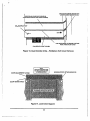
s-i
REAR
PL1
V IEW
REAR
V IEW
I H I
3
2
1
SI
LOW
T1-W1
'<y^^
SPLICE
SPLICE
"2
SCHEMATIC
»3
.
I
-\
FOR REPAIR INFORMATION OR REPLACEMENT PARTS ASSISTANCE, PLEASE
CONTACT YOUR NEAREST CUSTOMER SUPPORT CENTER LISTED IN THE BACK
OF THIS MANUAL.
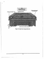
SERVICE MANUAL
FOR
FISHER AUTOMATIC CO2
WATER-JACKETED INCUBATORS
Models covered by this manual:
116875
116875H
1168751
1168751H
1168710
116871 OH
11687101
11687101H
NOTICE
THE MATERIAL IN THIS MANUAL IS FOR INFORMATION PURPOSES ONLY.
THE CONTENTS AND THE PRODUCT IT DESCRIBES ARE SUBJECT TO
CHANGE WITHOUT NOTICE. FISHER SCIENTIFIC MAKES NO
REPRESENTATIONS OR WARRANTIES WITH RESPECT TO THIS MANUAL.
IN NO EVENT SHALL FISHER SCIENTIFIC BE LIABLE FOR ANY DAMAGES,
DIRECT OR INCIDENTAL, ARISING OUT OF OR RELATED TO THE USE OF
THIS MANUAL.
FISHER SCIENTIFIC
CORPORATE HEADQUARTERS
711 FORBES AVENUE
PITTSBURGH, PA 15219
REV. D
DATED 9-11-95
MANUAL P/N 512S-AZ-4
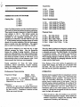
SERVICE MANUAL TABLE OF CONTENTS
SECTION
PAGE
INTRODUCTION
1
PART1
1.1
1.2
1.3
DESCRIPTION OF SYSTEM OPERATION
TROUBLESHOOTING THE INCUBATOR SYSTEM
CALIBRATION
1.3.1 TEMPERATURE DISPLAY CALIBRATION
1.3.2 SAFETY SET POINT CALIBRATION
1.3.3 RELATIVE HUMIDITY CALIBRATION
1.3.4 COj CALIBRATION
1.3.5 THERMOCONDUCTIVECOj SENSORS
1.3.6 GAS SAMPLES
1
4
6
6
6
7
7
8
8
PART 2
TEST PROCEDURES
2.1
POWER SWITCH/EMI FILTER
2.2
TRANSFORMER
2.3
POWER PRINTED CIRCUIT BOARD
2.3.1 POWER BOARD CALIBRATION
2.4
CONTROLLER CIRCUIT BOARD
2.5
CHAMBER HEATER
2.6
DOOR HEATER
2.7
AUXILIARY CHAMBER HEATER
2.8
FAN MOTOR
2.9
COj SOLENOID VALVE
2.10 FLOAT SWITCH
2.11 TEMPERATURE SENSOR
2.12 T/CCOj SENSOR
2.13 I/RCO2 SENSOR
2.14 RELATIVE HUMIDITY SENSOR
9
9
10
10
11
12
12
13
13
13
14
14
15
15
15
15
PART 3
REMOVAL/REPLACEMENT PROCEDURES
3.1
SHELF SUPPORTS & BLOWER DUCT
3.2
SOLENOID VALVES
3.3
T/C COj SENSOR
3.4
I/R CO2 SENSOR ASSEMBLY
3.5
TEMPERATURE SENSOR
3.6
RELATIVE HUMIDITY SENSOR
3.7
FAN MOTOR
3.8
CARTRIDGE HEATERS
3.9
AIR HEATER
3.10 DOOR HEATERS
3.11 AUXILIARY CHAMBER HEATER
17
17
17
17
17
18
18
18
18
19
19
19
iii
SERVICE MANUAL TABLE OF CONTENTS (cont.)
SECTION
3.12 FLOAT SWITCHES
3.13 INNER GU^SS DOOR
3.14 OUTER DOOR
3.14.1 SINGLE CHAMBER UNITS
3.14.2 DOUBLE CHAMBER UNITS/LOWER DOOR
3.14.3 DOUBLE CHAMBER UNITS/UPPER DOOR
3.15 WATER-JACKET CHAMBER MODULE
3.15.1 SINGLE CHAMBER UNITS
3.15.2 DOUBLE CHAMBER UNITS/LOWER DOOR
3.15.3 DOUBLE CHAMBER UNITS/UPPER DOOR
3.16 FUSES
3.17 CONTROLLER BOARD ASSEMBLY
3.18 POWER CIRCUIT BOARD
3.19 TRANSFORMER
3.20 EMI FILTER
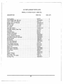
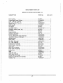
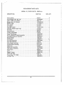
3.21 REPLACEMENT PARTS LIST
Model 5 (100/120 Volts - 50/60 Hz)
Model 5H (100/120 Volts - 50/60 Hz)
Model 51 (100/120 Volts-50/60 Hz)
Model 51H (100/120 Volts - 50/60 Hz)
Model 10 (100/120 Volts-50/60 Hz)
Modeli OH (100/120 Volts - 50/60 Hz)
Model 101 (100/120 Volts-50/60 Hz)
Model 101H (100/120 Volts - 50/60 Hz)
PAGE
20
20
20
20
21
22
23
23
24
25
26
26
27
27
27
28
28
29
30
31
32
33
34
35
PART 4
ILLUSTRATIONS, FIGURES AND SCHEMATICS
FIG. NO.
PAGE
1.
CONTROL PANEL
2.
CONTROLLER BOARD REMOVAL
3.
POWER CIRCUIT BOARD
4.
DOOR HEATER & ATTACHING PARTS
5.
TOP COVER REMOVED
6.
REAR VIEW-COVER REMOVED
7.
FAN MOTOR PLATE
8.
I/R INTERFACE BOARD AND REATED COMPONENTS
9.
SHELF SUDE REMOVAL
10.
BLOWER DUCT REMOVAL
11.
SHELF SLIDE
12.
TOP COVER REMOVAL
13.
DUAL CHAMBER UNITS - FILL/SIPHON PORT COVER REMOVAL
14.
LOWER DOOR SUPPORT
15.
UPPER DOOR SUPPORT BRACKET
WIRING DIAGRAMS & SCHEMATICS
U.S. CUSTOMER SUPPORT CENTERS
iv
36
36
37
37
38
38
39
39
40
40
41
41
42
42
43
44
45
PART1
DESCRIPTION OF SYSTEM OPERATION
TROUBLESHOOTING
TEST PROCEDURES
each door mounted controller. The incubator is
completely automatic, easy to maintain and
service in your laboratory. The following is a
description of the system and how it operates.
The control systems are housed in each door, vAth
signal conditioning and processing sent to a power
INTRODUCTION
board at the rear of the incubator. Most
troubleshooting procedures for this system can
This manual covers the maintenance and be earned out with the rear covers removed and
servicing ofthe Model 5, 10, 51, and 101 series the controller pulled to the "Service Position." All
of Fisher automatic COj v/ater jacketed electrical wires are identified and referenced to
terminal connections in accordance with the
incubators.
schematic diagrams. All components and tubing
connections can also be examined. The shelves,
NOTE
shelf support panels, and blower ducts are easy
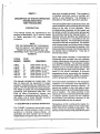
FOR THE REMAINDER OF THIS MANUAL.
to removed from the chambers for cleaning. With
AND TO SIMPLIFY UNIT DESIGNATIONS.
these assemblies removed, the chamber walls can
FISHER CATALOG NUMBERS WILL BE
be cleaned without interference. There are no
REFERRED TOBY THE FOLLOWING MODEL hard-to-clean areas.
NUMBERS:
Catalog
Number:
Model
Number:
116875
116875H
1168751
1168751H
1168710
1168710H
11687101
11687101H
5
5H
51
51H
10
10H
101
101H
Description:
Single Chamber. T/C CO,
Single Chamber, T/C CO^ RH
Single Chamber. I/R COj •
Single Chamber, I/R CO, RH
Double Chamber, T/C CO,
Double Chamber, T/C CO, RH
Double Chamber, I/R CO,'
Double Chamber. I/R CO, RH
Each water-jacket chamber is manufactured
individually and mounted into the incubator
chassis, allowing easy removal and replacement
of a damaged chamber. The chamber modules
have been conveniently fitted with a combination
fill/siphon port so the water jackets can be filled
or emptied with the same hose connection. The
water in the jacket maintains a constant
temperature source surrounding the chamber,
enhancing the incubator's ability to provide a
uniform temperature throughout the chamber
This manual is divided into 4 basic parts. Part All environmental parameters in the incubator's
One (1) deals vi'ith the description of system chambers are monitored and regulated by
operation, troubleshooting and calibration of the microprocessor-based electronic controls. All
system. Part Two (2) deals with test procedures. sensors are located on the motor plate of each
Part Three (3) deals with removal/replacement individual chamber, as are the gas injection ports,
procedures, and replacement parts lists. Part and air heaters. The close proximity of the
Four (4) offers illustrations, figures, and sensors to the control devices pemnits the system
schematics for troubleshooting the incubator. It to maintain precise control over the chamber
also offers a list of Fisher Scientific customer environment and efficient recovery of the
support centers and phone numbers.
environment after the door is opened.
1.1 DESCRIPTION OF SYSTEM OPERATION
The FISHER incubators described herein
incorporate microprocessor based control
systems in a modular chassis design. All
parameters for each chamber can be entered
independently through the set point switches on
Temperature control is achieved by means of a
temperature sensor located on the motor plate,
which monitors the chamber temperature. The
primao' control circuits provide proportional control
to the heaters, thereby eliminating temperature
overshoot. A safety temperature control also
monitors the chamber temperature through the
primary temperature sensor. In the unlikely event
the primary temperature control circuit' fails, and
tries to heat the chamber continuously, jthe safety
temperature control will remove power from the
chamber heaters, thus eliminating a Irun away
temperature condition. When set properly, the
safety temperature control can easil>^ limit the
maximum chamber temperature to within +1.0'C
of the set point entered with the primary control.
i
The unit is equipped with heated exterior doors
which remove a majority of the condensation from
the inner glass doors. This feature enables
laboratory personnel to make a visual check of
the incubator's contents without distiirbing the
incubator atmosphere. The door heaters are
controlled by the same circuitry that controls the
chamber heaters.
|
There are four (4) heaters for each [chamber,
consisting of two cartridge heaters located in the
bottom of the water jacket, directly heating the
water, one auxiliary heater located on tHe exterior
top of the chamber, to eliminate ceiling
condensation, and one air heater mourited to the
fan motor plate. The air heater extends info the
area enclosed by the fan blower duct at the rear
of each chamber, which heats the atmosphere
within the chamber The circulating fanl draws air
in from the bottom of the chamber, moves the air
across the air heater and up the blower duct, and
then re-enters the chamber at the top. i
When COJ is introduced into the chamber, the
COJ has an insulating effect on the exposed
section of the sensor This causes the exposed
thermistor temperature to increase, causing a
voltage imbalance between the reference and
sensing sections, which is compared by the
analog circuitry. If the COj level sensed is below
set point, the control circuit will proportionally
control the CO2 solenoid valve, and meter small
amounts of COj into the chamber, as required.
Proportional control accounts for less deviation
in the amount of COj fluctuation within the
chamber
Normally, CO^ levels are affected by changes in
relative humidity, when using a thermalconductivity type COj sensor. Care must be taken
to avoid wide changes in operating relative
humidity levels, in order to maintain good CO2
control accuracy. Re-calibration of the COj control
will be necessary when changing to a different
operating relative humidity.
The Infra-Red (1/R) type of COj sensor (Model
51H or 101H) works on the principle of detecting
the amount of 1/R energy absorbed by the CO2.
An l/R source is energized at predetermined
intervals. This source is passed through a special
filter (lens) and then passed on to an 1/R detector
The amount of 1/R energy is measured by the
analog circuitry.
When CO2 is introduced into the chamber, some
ofthis CO2 gas is passed through the optimal path
inside the CO2 sensor As the COj level increases,
the amount of 1/R energy absorbed increases.
The CO2 percentage in each chamber is This amount of energy is measured and
maintained independently by the electronic compared by the analog circuitry. Ifthe CO2 level
controls and either a thermo-conductivity type CO2 is below set point, the control circuit will
sensor (Model 5H or 10H), or an lnfra--Red type proportionally control the COj solenoid valve as
CO2 sensor (Model 51H or 101H). The different before. The I/R COj sensor is not significantly
affected by changes in operating relative humidity.
types of CO2 sensors are explained beiow.
The themio-conductivity type COj sensor (Model
5H or 10H) consists of a matched set of themiistor
beads operating at an elevated temperature. One
side of the sensor (reference section) is
hemnetically sealed, and senses only the chamber
temperature. The other side is exposed to both
chamber temperature and atmosphere.
Relative humidity Is measured by using a solidstate type humidity sensor mounted on the motor
plate. The snsor monitors the relative humidity
level within the chamber, which in tum is diaplayed
on the front panel. It will monitor conditions from
ambient to 99.0% relative humidity The "tenths"
digit s always fixed at "0".
Relative humidity is provided by pouring distilled by connecting a voltage type chart recorder to
water directly into a tray, whicy can be placed on this jack. In this way complete temperature
a helf or, if desired, by pouring the water directly documentation can be provided along with the
onto the chamer floor Pouring th water onto the experiment or project. The output to the recorder
floor will hep maintain the highest relative humidity is 10 mv/°C. This output does not monitor COj.
obtainable. However, this water should not be
placed directly on the chamber floor when active The 1/4" phone jack, provided next to the recorder
chemicals to reduce fungus and mold growth are jack, can be used to connect the Incubator to a
involved.
central monitoring system. The jack can be wired
either as "Normally Closed" or "Normally Open".
These units are also equipped with a temperature There are "Fonn C" contacts used for the output
recorder jack and a provision for connection to a of this jack. Alarm conditions that will activate
central monitoring system. The temperature this jack are High Temperature, Low or High COj
recorder jack allows the user to monitor each concentrations, and a safety set point adjusted
incubator operating temperature independently. below the desired operating set point.
1.2 TROUBLESHOOTING THE INCUBATOR
SYSTEM
1.
2.
3,
Too much condensation on glass
door
C02 not regulating
Displays not lighted
1.
Door heater faulty; see Section 2.6
2.
Low or no voltage: check connections and wiring
to Power circuit board; see Section 2.3
3.
Fan motor defective; see Section 2.8
1.
Check if C02 supply tank is empty
2.
Check C02 tubing for leaks, kinks, bends, or bad
connections.
3.
Check C02 solenoid; see Section 2.9
4.
Defective Controller board; see Section 2.4
5.
+ 7.35 volt supply not adjusted properiy; see
Section 2.13
6.
7.
Fuse on 1/R interface board defective; see Section
2.13
0 0 2 sensor defective; see Section 2.12, 2.13
8.
Fan motor defective; see Section 2.8
1.
Power circuit board not adjusted properly or
defective power circuit board; see Section 2.3
2.
Power circuit board fuse blown; see Sections 2.2
& 2.3
Transformer defective; see Section 2.2
3.
4.
5.
6.
Displays show random data
No DC power.
DC voltages below nonnal.
1.
Power circuit board not adjusted properly or
defective power circuit board; see Sectio 2.3
2.
Defective controller board; see Section 2.4
1.
2.
Check fuse F-1 on Power circuit board; see
Section 2.3
Check if there is AO power to the AC input
terminals of the power circuit board. If not, check
EMI filter fuses; see Section 2.1.
3.
Power circuit board defective; see Section 2.3
4.
Transformer defective; see Section 2.2.
1.
Disconnect J-10 from power circuit board to see if
Controller board is loading the power supply.
2.
Power circuit board calibration; see Section 2.3.
6.
7.
8.
9.
DC voltages below normal.
No AC power.
Temperature above set point and "HI"
temp, indicator on.
Temperature in chamber not the same as
that displayed.
1.
Disconnect J-10 from power circuit board to
see if Controller board is loading the power
supply.
2.
Power circuit board calibration; see Section
2.3.
1.
Defective AC power switch in EMI filter; see
Section 2.1.
2.
Fuse blown in EMI Alter; see Section 2.1.
3.
Defective power
1.
Defective temperature sensor; see Section
2.11.
2.
Defective Controller board; see Section 2.4.
1. Temperature
cord.
calibration; see Section
2.
Check
3.
Temerature
2.11.
4.
Fan motor defective; see Section 2.8.
1.
Safety temperature control set below
temperature set point; see operator's
manual.
2.
Heating element(s)
2.5, 2.6 & 2.7.
3.
Defective Power circuit board; see Setion
2.3
4.
Fan motor defective; see Section 2.8.
5.
Tempreature
2.11.
11. Low water indicator LED on and chamber
known to be full. Low water LED off and
chamber known to be low on water.
1.
Float switch defective; see Section 2.10
12. Relative humidity display indication too high
(above 99.0%)
1.
R.H. calibration; see Section 1.3.
2.
Defective R.H. sensor; see Section 2.14.
1.
R.H. water supply depleted; see operator's
manual.
2.
Defective door seals or fan motor plate gaskets;
repair and replace as necessary.
R.H. calibration; see Section 1.3.
10. Temperature too low.
13. Relative humidity display indication appears
too low.
3.
temperature
sensor
sensor
sensor
1.3.
connection.
defective; see Section
defective; see Sections
defective; see Section
2. Allow the incubator to stabilize for a minimum
of one (1) hour and check the temperature
readings. Recalibrate if necessary.
1.3 CAUBRATION
The calibration procedure is used to adjust the
Temperature display, Safety Set Point and COj
parameters. Read this section carefully before
attempting to calibrate the unit. Follow this
procedure for the most accurate calibration. CO,
must be calibrated last for best accuracy. It is
assumed that the incubator is to be operating at
37.0°C. You can however operate at any desired
temperature from 5*C above ambient to 50.0'C.
WARNING
HANDLE MERCURY THERMOMETERS WITH
THE UTMOST CARE. MINUTE AMOUNTS OF
MERCURY IN THE INCUBATOR FROM A
BROKEN THERMOMETER MAY CAUSE
DAMAGE TO THE CHAMBER BY
ELECTROLYSIS. AS WELL AS CREATING A
TOXIC ENVIRONMENT WITHIN THE
CHAMBER, RENDERING THE INCUBATOR
USELESS.
Prior to calibration, the CO2 supply should be shut
off. Be sure the CO2 set point is set for "00.0".
Place an accurate thermometer in the center of
1.3.2 SAFETY SET POINT CALIBRATION
the chamber so it can be read with the glass door
closed. Now the door must be CLOSED for a When the "SAFETY SET PT" button is pressed,
minimum of one (1) hour before performing the the "TEMP "C" window displays the set point of
calibration procedure.
the back-up overtemperature control. Normally,
this setting is between 0.5° and 1.0'C above the
IF THE INCUBATOR IS BEING OPERATED
desired operating temperature (The desired
FOR THE FIRST TIME OR HAS BEEN OUT OF operating temperature was determined when you
SERVICE FOR SOME TIME, THEN THE
selected the temperature with the set point
INCUBATOR TEMPERATURE MUST HAVE A switches.). This will allow the incubator to heat
CHANCE TO STABILIZE. WE RECOMMEND properiy under normal conditions. In the unlikely
THE UNIT BE IN OPERATION FOR ABOUT 24 event of a primary control failure, the back-up
HOURS BEFORE ATTEMPTING
control acts as a guard to prevent the incubator
CALIBRATION.
chamber from overheating more than this set
value. Proper calibration of the safety set point
1.3.1 TEMPERATURE DISPLAY CALIBRATION can not be overstressed.
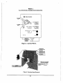
1. An accurate thennometer should have been
placed in the center of the incubator chamber
previously. Read the thermometer and
compare it with the temperature display If
the display and the thermometer readings
disagree, open the outer door and remove two
(2) screws from the top of the control module.
See Figure 1. Pull the control module up about
three (3) inches until it locks in place, see
Figure 2. On the right side of the control
module are four (4) potentiometers. The top
potentiometer (R-8) Is used to adjust the
temperature display. Adjust R-8 until the
display agrees with the thermometer inside
the chamber Push the retainer in to release
the control module. Slide the control module
back into the door. Close the outer door
6
From this you can also see that if the back-up
overtemperature control is set below the desired
operating temperature, the incubator will never
heat. So if you decide to change the desired
operating temperature, you must readjust the
back-up overtemperature control.
If the overtemperature control set point is set equal
to or less than the desired operating temperature,
the "HI" temperature LED will flash, and the
audible alarm will sound.
1. Press the "SAFETY SET PT." button. Ifthe
displayed reading is between 0.5° and 1.0*C
above the desired operating temperature, then
no further calibration of the back-up
overtemperature control is needed.
2. If calibration is required, then open the outer
door and pull the control module up about
three (3) inches until it locks in place. See
Figure 2. On the right side of the control
module are four (4) potentiometers. The third
potentiometer (R-10) is used to adjust the
back-up control. While pressing the "SAFETY
SET PT" button, adjust R-10 until the display
reads between 0.5° and 1.0°C above the
desired operating temperature. Push the
retainer in to release the control module. Slide
the control module back into the door before
attempting to close the door
reaings disagree, open the oute door and
remove two (2) screws from the top of the
control module. See Figure 1. Pull the control
module up about three (3) Inches until it locks
in place. See Figure 2. On the right side of
the control module are four (4) potentiometers.
The bottom potentiometer (R-11) is used to
adjust the R.H. display. Adjust R-11 until the
display agrees with your hummidity
instnjment. Push the retainer in to release
the control module. Slide the control module
back into the door and close the outer door
1.3.4 CO2 CALIBRATION
1.3.3 RELATIVE HUMIDITY CAUBRATION
Normally the Relative Humidity Display will not
require calibration. As a matter of fact,
sophisticated equipment is required to verify
calibration. Home ype humidity gauges are not
considered accurate. Their accuracy drops off
dramatically in the upper humidity levels where
the Inclbator normally operates.
1. Place an accurate humidity probel on the
middle shelf of the incubator Close the door
and allow the unit to stabilize for a minimum
of one (1) hour
2. Compare the reading of your humidity
instrument with the Relative Humidity Display.
If the display and the humidity instrument
Now that the temperature controls have been
calibrated properly, you will be finishing the
calibration procedure by adjusting the CO2. Again,
we will assume the doors have been closed a
minimum of one (1) hour, and that the incubator
is operating at the desired temperature and
relative humidity. Remember, a tray of cool water
placed in the chamber to provide humidity could
take up to eight (8) hours before it reached the
same temperature as the chamber There should
not be any COj in the chamber, since the gas
supply has not been tumed on yet, and the CO2
set point is set to "00.0".
NOTE
MODELS 5, 5H, WAND 10H ARE SENSITIVE
TO CHANGES IN OPERATING RELATIVE
HUMIDITY THESE UNITS MUST BE
CALIBRATED AT THE DESIRED OPERATING
RELATIVE HUMIDITY. KEEPING THE DOOR
CLOSED A MINIMUM OF 1 HOUR WILL
ASSURE THIS CONDITION.
humidity will cause the CO2 display to fall.
Conversely if humidity decreases, the COj display
will rise. Also an increase or decrease in
temperaure will cause the display to rise or fall.
When the gass door is opened, the rapid change
in relative humidity may cause the COj display to
rise, contrary to what would be logical. The
change is momentary and will stabilize quickly
1. Open the outer door and pull the control
module up about three (3) inches until it locks
in place. See Figure 1. On the right side of
the control module are four (4) potentiometers.
The second potentiometer (R-9) is used to
adjust the COj display Adjust R-9 until the
display reads "00.0". This will "ZERO" the
display. Push the retainer In to release the
control module. Slide the control module back
into the door and close the outer door.
If you change the operating relative humidity level
for any reason on Models 5H or 10H, re-cafibration
of the CO2 control system is required. This is a
natural physical phenomenon common to all
thermo-Conductivity type COj sensing systems,
most users do not change thir operating relative
humidity, so this is not normally a concern. The
basic principle behind obtaining a diferent
operating relative humidity is based on the amount
of surface area of water provided by the humidity
tray or dish. There are other factors such as the
Tum the COj supply ON. Adjust the COj line integrity of the chamber seals, etc. Under stable
pressure between 15 and 25 PSI. (1.0-1.7 temperature and relative humidity conditions,
BAR.) Enter the desired COj level with the FISHER'S thermo-conductivity type CO, sensing
CO2 set point switches. Allow the unit to systemsrivalInfra-Red type CO, sensing systems,
when comparing control accuracy.
stabilize for a minimum of one (1) hour.
3. Take a gas sample, from the "Gas Sample
Port" with COJ measuring instrument. The
displayed reading and the actual reading from
yourC02 measuring instrument should agree.
If not, open the outer door and pull the control
module up and re-adjust potentiometer (R-9),
until the two readings agree.
4. Push the retainer in to release the control
module. Replace the two (2) control module
screws and close the door
1.3.5 THERMOCONDUCTIVE CO, SENSORS
Users with the desire or need to change their
operating relative humidity frequently or for those
who open and close the inner door many times
on a daily basis (which tends to lower the average
relative humidity within the chamber) will benefit
the most from the Infra-Red type C02 sensing
system models (Models 51,51H, 101 and 101H).
Infra-Red C02 sensing systems are not adversely
affected by wide chanes in relative humidity.
1.3.6 GAS SAMPLES
Gas samples are taken with a suitable sampling
instrument ("Bacharach Fyrite" or Blood Gas
A themoconductive (TC) CO2 Sensor consists of Analyzer for example) through the gas sample
exposed and sealed sensing sections. The sealed ports.
section of the sensor is isolated from ambient
atmosphwere and is not affected by changes in
CO, concentration or relative humidity. This
section is used as a reference level. The exposed
section reacts with changes in COj concentration,
relative humidity and temperature. Any sudden
change in any of those parameters will cause the
sensor to rapidly react to the change. Increasing
Part 2
TEST PROCEDURES
WARNING
CHANGING THE FUSE HOLDER VOLTAGE
CONFIGURATION DOES NOT CHANGE THE
OPERATING VOLTAGE OF THE UNIT DO
NOT ATTEMPT TO USE THIS FOR THAT
PURPOSE. THE UNIT OPERATING VOLTAGE
IS CONFIGURED AT THE FACTORY AT THE
TIME OF ASSEMBLY.
NOTE
VOLTAGE AND RESISTANCE
MEASUREMENTS ARE TAKEN ACROSS THE
PART UNDER TEST ALWAYS REMOVE
POWER CORD FROM ELECTRICAL OUTLET
4. Connect the power cord to the EMI filter, and
WHEN REMOVING A WIRE FOR TESTS.
tum on the power switch. If voltage is still not
NEVER MAKE A RESISTANCE CONTINUITY
present, and the fuses are known to be good,
MEASUREMENT WHILE UNIT IS PLUGGED
replace the EMI filter
INTO ELECTRICAL OUTLET REFER TO
ENCLOSED SCHEMATICS AND
5. If the fuses continue to open, remove the black
ILLUSTRATIONS TO AID IN TESTS.
and white wires from the EMI filter Check the
voltage at this connection again. If voltage is
2.1 POWER SWITCH/EMI FILTER
now present there is a short circuit in the unit.
(A short circuit would cause the fuse(s) to
1. Turn on power switch, located on left side of
continually open. This is why no voltage was
unit, next to the power cord.
present when the black and white wires were
connected to the EMI filter.)
2. Check voltage across the EMI filter where the
black and white wires are connected. See
6. To isolate a short circuit, reconnect the wires
Figure 6.
to the EMI filter (after removing power to unit).
Remove Connectors J-3. J-4, and the wires
3. If no power is indicated at the above
from
Connector J-5 from the power circuit
connection, disconnect the power cord and
board,
one at a time.
check the fuses inside the EMI filter This is
accomplished by prying the cover off the fuse
holder section of the EMI filter The cover is 7. Tum the power switch to the ON position.
When the fuse(s) stop opening, you have
located beneath the power switch. The fuses
isolated the short circuit. If the fuse(s) stop
can be visually checked or checked with an
opening after removing connector J-3, look
ohmmeter on the low resistance scale. The
for a defective water jacket heater or door
resistance should be less than 0.2 ohm.
heater If they stop after removing J-4, look
When replacing the fuse holder, be sure the
for a defective fan motor, or air heater If they
fuse holder orientation coincides with the
stop after removing the wires from J-5, look
electrical configuration of your unit. This is
for a defective auxiliary heater. Leave
accomplished by aligning the arrows on the
voltmeter connected across EMI filter to
fuse holder for the proper voltage.
monitor voltage.
8. If the short circuit is still not isolated, remove
Connector J-2 from the circuit board. If the
fuse(s) stop opening, the short circuit is on
the power circuit board.
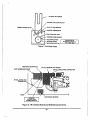
Connector J-2 is the primary power input to the
circuit board. Pin 1 being ground, Pin 2 is the
common, and Pin 3 as the primary or "Hot"
connection.
Connector J-3 supplies controlled output to the
water jacket cartridge heaters and door heater.
The transformer located above the power circuit Pins 1 & 2 supply the left cartridge heater. Pins 3
board provides isolated power for the secondary & 4 supply the right cartridge heater. Pins 5, 6, 7
components. See Figures 3 and 6. The primary & 8 supply the door heater, with Pin 8 being
of the transformer is multi-taped to allow an input ground. The connections are configured using
of 120 Volts. The secondary is a center-tapped the two voltage select jumpers located above
design providing an isolated UL Class 2 rating of Connector J-3.
9.5 Volts to the power circuit board. The 3/8
Ampere fuse (F-1) soldered to the power circuit Connector J-4 supplies controlled output to the
air heater through Pins 5 & 6. J-4 also supplies
board protects the transformer primary.
power to the fan motor through Pins 4,7 & 8, with
1. If there isn't any power to the controller, check Pin 4 being ground for the fan motor plate. Pins
the power circuit board fuse. If it is open, 1, 2 & 3 are generally not used except for an
replace the fuse with the same type and rating. optional electrical outlet located inside the
chamber.
See Figure 3.
2.2 TRANSFORMER
2. If the fuse continues to open, the transformer
may either be shorted, or a secondary
component may be shorted. To isolate the
transformer from the secondary components,
remove the secondary wires from Connector
J-1, This will be two (2) red wires and one (1)
red/yellow wire on the right end of Connector
J-1. See Figure 3.
3. If the fuse continues to open, replace the
transformer. Refer to Section 3.19 for
transformer replacement.
2.3 POWER PRINTED CIRCUIT BOARD
The power printed circuit board is located on the
back of the unit behind the rear cover The power
circuit board interfaces with the controller board,
as well as the CO, sensor and solenoid valve,
temperature sensor, and heaters. All power enters
the power circuit board, which in tum powers or
controls all other components on the unit.
Connector J-5 is the last AC connector It is used
for connection of the auxiliary chamber heater
Pin 1 is common.
Connector J-6 is actually a pair of wires that are
soldered In place which supplies 5 volts DC to
the CO2 solenoid valve. Pin 1 is the positive (+)
terminal. Pin 2 is the negative (-) terminal. The
solenoid valve itself however, is not polarity
dependent.
Connector J-7 connects the water jacket float level
switch into the circuit. The float switch is
connected in series with an LED on the controller
board through the power circuit board to give an
indication of the water level in the water jacket.
Connector J-8 is used for interfacing the InfraRed (1/R) type CO, sensor circuitry used on Model
51H or 101H. An interface board is connected
here. Pin 1 is the unregulated DC source of the
interface board. Pin 2 is ground. Pin 3 is the
output from the l/R CO2 sensor. Pin 4 is analog
Refer to Figure 3. Connector J-1 is the ground. Pin 5 is used for the shield. When the 1/
transformer connector. Pins 1 through 3 are the R type CO, sensor is used, the jumper located
secondary terminals. Pin 2 being the center tap between components R-1 and C-3 must be
and Pin 6 for 120 Volts. Pin 8 is the common configured for the "1/R" position.
terminal.
10
Connector J-9 is a 20-pin connector that connects through many electronic supply stores. The plug
the controller to the power circuit board. The is manufactured by Switchcraft. (Switchcraft P/N
following table shows the pin designations.
850.)
CONNECTOR J-9 PIN DESIGNATIONS
PIN NUMBER
1
2
3
4
5
6
7
8
9
10
11
12
13
14
15
16
17
18
19
20
Connector J-13 is also an optional connection for
monitoring the incubator through a central
monitoring system. Any alarm condition will
activate relay K-2, thereby alerting the central
monitor J-13isa3-conductorjack. This enables
configuration either as "NORMALLY CLOSED" or
"NORMALLY OPEN" as required by the
monitoring system. The case of J-13 is ground.
The tip connection is "NORMALLY CLOSED".
Again the mating plug can be purchased through
many electronic supply stores. The plug is
manufactured by Switchcraft. (Switchcraft P/N
260.)
PIN DESIGNATION
+5 VDC Digital Source
Digital Ground
+5 VDC Digital Source
Digital Ground
Solid State Relay (Triac)
Solenoid Valve
Safety Relay
Alarm Relay
Digital Ground
Float Switch
I/RCO2
Sensing (Relative Humidity)
Analog Ground
Sensing (T/C CO,)
Analog Ground
Reference (T/C CO,)
Analog Ground
Temperature
Analog Ground
Unregulated DC
Connector J-14 is used for connection to the
relative humidity sensor Pin 1 is the unregulated
DC source. Pin 2 is theoutput from te relative
humidity sensor, Pin 3 is analog ground.
2.3.1 POWER BOARD CALIBRATION
Normally the power circuit board is calibrated at
the factory. If however you find that the calibration
is not correct, follow these steps for proper
calibration.
Connector J-10 is used for connection to the solid
state temperature sensor Pin 1 is the +5 VDC 1. Disconnect electrical service from unit.
source, Pin 2 is the output from the temperature
2. Disconnect harness Connectors J-9 and J-10
sensor. Pin 3 is analog ground.
from the power circuit board. See Figure 3.
Connector J-11 is used to connect thermoconductivity (T/C) type CO2 sensor to the power 3. TC/IR Jumper must be in the TC position for
calibration purposes. On Models 51,51H, 101
circuit board. The T/C type CO, sensor is used
and 101H, reset jumper to IR position after
on Model 5H or 10H. Pin 1 is the sensing
calibration and checking (Step 7) are
connection, Pin 2 is analog ground, Pin 3 is the
complete.
reference connection. When the T/C type CO,
sensor is used, the jumper located between
components R-1 and C-3 must be configured for 4. Attach a voltmeter across Pins 1 & 3 (-) on
the "T/C" position. See Figure 3.
Connector J-10.
Connector J-12 is an optional output for
connection to a temperature recorder for the sole
purpose of monitoring the chamber temperature.
The output is 10 mv/°C. The tip connection is
positive (+). The mating plug can be purchased
5. Connect electrical service to unit. Adjust R10 for an output of +5.1 volts. The accuracy
of this calibration is critical.
6. Next, remove the test lead from Pin 1 and
attach it to the junction of R-2/R-3 (right side
of R-2/R-3). See Figure 3. This junction is
11
located near capacitor C-5. Leave the other
test lead attached to Pin 3 on Connector J10.
If a valid set point is not entered, the controller
will not allow the unit to heat, inject CO, or both.
Valid set points for temperature control are 0.1 to
50.0'C. Valid set points for CO, control are 0.1 to
7. Adjust R-9 for an output of+7.35 volts. Again, 20.0%. Naturally a set point of 0.0 for either
the accuracy ofthis calibration is critical. temperature or CO, tums off that function.
8. Disconnect the power to the unit. Reconnect
harness connectors J-9 & J-10 to the power
circuit board. Apply power to the unit, and
recheck the calibration. Adjust as necessary.
The only calibration required in the field is
adjusting the temperature display, safety setpoint
and CO2. These procedures are described in
Section 1.3. Do not attempt to adjust
potentiometers R-15, R-16, R-17, or R-18. If
9. If the above conditions cannot be met, replace other problems are suspected with the board, it is
the power circuit board. Refer to Section 3.18 highly recommended you contact your local Fisher
Scientific representative for service suggestions.
for power circuit board replacement.
The controller board is designed for easy removal
and replacement. Refer to Section 3.17 for
2.4 CONTROLLER CIRCUIT BOARD
controller board assembly replacement.
The controller assembly located in the door
consists of two (2) boards, the digital display
2.5 CHAMBER HEATER
board, and the CPU board. These boards contain
the digital displays, set point switches, alarm There are four (4) heaters for each chamber,
indicating and regulating LED's. The controller consisting of two (2) cartridge heaters located in
also houses the safety set point and silence the bottom of the water jacket, directly heating
switches. The controller incorporates an Intel the water, one (1) auxiliary chamber heater
8051 series micro-controller with a 27C256 located on the top of the water jacket (refer to
EPROM. Since the controller uses mechanical Section 2.7), and one (1) air heater mounted to
switches for setting temperature and CO, the fan motor plate, which heats the atmosphere
parameters, a battery back-up for memory within the chamber The air heater is protected
retention is not required.
with a limiting thennostat, which is mounted to
the fan motor plate. All heaters are rated at 100
The edge connector fingers are designated the watts each, with the exception of the auxiliary
same as Connector J-9 on the power circuit board. chamber heater, its rating being 50 watts. This
See Figures 1 8i 3. The even numbered fingers yields a total of 350 watts heat capacity.
are located on the front side of the board, the
To test the cartridge heaters:
odd numbered fingers are on the back side.
Jumper JP-1, also located above U-2 selects the
configuration for the type of CO, sensing system
that is used. JP-2 would be set for the "OUT'
position for T/C units. Models 51, 51H, 101 and
101H use the Infra-Red (I/R) CO, sensor This
jumper must be set properiy for your type of CO,
sensor
1. Disconnect electrical service from unit.
2. To provide access to cartridge heaters,
remove the rear cover which exposes the
power circuit board. See Figure 6.
3. Remove Connector J-3 from the power circuit
board. See Figure 3. With an ohmmeter,
measure at connector J-3, between Terminals
Jumper J P-3, located to the left of U-2 configures
1 and 2. then Tenninals 3 and 4. The following
the relative humidity sensor to be in circuit on
resistance values should be met:
these models. This jumper should always be set
for the "OUT" position.
12
120 volt operation: 320 ohms, -10 + 0% (cold
resistance).
120 volt heaters: 140 ohms + 10% (cold
resistance).
4. With Connector J-3 still removed from the 2. If the above values are not met, replace the
power circuit board, measure resistance from
door heater. Refer to Section 3.10 for door
heating element case to one of its wires.
heater replacement.
Select highest range on ohmmeter Do not
touch test leads with hand. Meter should read
2.7 AUXILIARY CHAMBER HEATER
infinity
The auxiliary chamber heater provides 50 watts
Any reading less than infinity indicates of heat to the top front edge of the chamber See
cartridge heater is shorting to ground. Figure 5. This reduces the possibility of
Replace faulty cartridge heater. Refer to condensation forming on the ceiling of the
Section 3.8 for cartridge heater replacement. chamber when operating at elevated relative
humidity.
To test the air heater(s):
This heater is provided with a limiting thermostat
5. Disconnect the wires at the air heater to limit the maximum temperature the heater can
terminals. See Figure 6. Measure the obtain. The limiting thermostat is built into the
resistance across air heater terminals. heater
Readings should be the same as for the
cartridge heaters shown above.
To test the auxiliary heater:
1. Disconnect electrical service from unit.
6. Next measure between heater sheath and
heater terminals. Meter should read infinity
7. If heater does not meet the above
specifications, replace air heater. Refer to
Section 3.9 for air heater replacement.
2.6 DOOR HEATER
2. Remove the 2 wires from Connector J-5 at
the power circuit board. See Figure 3.
3. Measure the resistance across these 2 wires.
The following values should be met:
120 volt operation: 280 ohms, +10% (cold
resistance).
There is a door heater inside each door, attached
to the door liner See Figure 4. Each heater has 4. If you initially obtain a reading of infinity (open),
two sections. Each section is rated at
and the unit is warm, wait a few moments in
approximately 40 watts. This yields approximately
case the limiting thennostat has opened. If.
80 watts per door The door heater is controlled
after a few moments the above values are not
by tfie chamber heater circuit. When the chamber
met, replace the auxiliary chamber heater
heaters are on, the door heater is on. The door
Refer to Section 3.11 for instructions on
heater eliminates a majority of the moisture on
auxiliary chamber heater replacement
the glass door The heaters are connected in a
parallel connection for 120 volt operation.
2.8 FAN MOTOR
To test the door heater:
1. Remove Connector J-3 from the power circuit
board. See Figure 3. Measure at Connector
J-3, Terminals 5 and 6, then at Terminals 6
and 7. The following cold resistance values
should be met:
The fan motor provides circulation of tfie chamber
atmosphere. Refer to Figures 6 & 7 in the
illustration section of this manual. The motor is
an induction type AC motor, running at line
voltage. The rotation of the motor is
counterclockwise as viewed from the rear of the
incubator.
13
The circulation of tfie atmosphere is vital for proper 1. Set the CO, set point to 20.0%. The green
operation of the incubator. Without proper
"REG" LED for COj should be on. The valve
circulation, poor control of the environment may
should be energized at this time. The valve
be experienced, relating to problems with
makes an audible click (although not very
temperature and CO, regulation.
loud), when energized. Monitor Uie voltage at
the solenoid coil.
The motor requires no servicing, as it uses
permanently lubricated ball bearings.
2. If the valve does not energize, disconnect boUi
wires at the coll and measure the resistance.
There is a metal plate which is used as an
The resistance should be approximately 53
interference shield. The metal plate is located
ohms + 10%. If not, replace solenoid valve.
between ttie fan motor and the I/R CO, sensor
Refer to Section 3.2 for solenoid valve
This shield is used to prevent electrical or
replacement.
magnetic interference from affecting the l/R type
CO, sensor found on Models 51, 51H, 101 and 3. When the valve Is closed, there should not
101H. This plate and any attached grounding
be any CO, flowing. The valve should be
conductors is vital to proper operation ofthe unit.
"Bubble Tight". Test this condition by placing
It is not used with the T/C type CO, sensor found
the end of the CO, injectfon tubing in a beaker
on Models 5H and 10H.
of water There should be no bubbles. Replace
solenoid valve if found faulty. Refer to Section
1. If a fan motor fails to operate, try turning the
3.2 for solenoid valve replacement.
motor shaft. If it is binding, check and make
sure the blower wheel is hot forced onto the
2.10 FLOAT SWITCH
motor shaft too far, orUiatitis binding against
the blower duct. If Uie blower duct is removed The float switch monitors the water level of the
for any reason, be sure the spacer is installed water jacket. See Figure 5. When the water level
on the long stud before re-installing. See drops a sufficient amount, the float switch contacts
Figure 7. This will keep the wing nut from close, and allows the "LOW WATER" indicator to
being over-tightened and causing the blower illuminate.
duct to bend and stop the blower wheel.
To test the float switch for a low water condition:
2. You should also check for line voltage at
connector J-4 Terminals 7 and 8 on the power 1. Siphon a sufficient amount of water through
the water fill/siphon port. (About three liters
circuit board. If voltage is present, disconnect
or less should be sufficient). The "LOW
motor and check continuity of coil. If coil is
WATER" indicator should illuminate. If not,
open, replace motor Refer to Section 3.7 for
siphon another four liters of water Ifthe "LOW
fan motor replacement.
WATER" indicator still does not illuminate,
replace the float switch.
2.9 CO, SOLENOID VALVE
The CO, solenoid valve is of the normally closed To test the float switch for a high water condition:
configuration. It is mounted at the lower left edge
of the power circuit board. Refer to Figure 6 in 2. Add three liters of water to the siphon/fill port.
the Illustration Section of this manual. It is
The indicator should tum off. If not, ad another
important to maintain a minimum of 20 PSI (1.5
four liters of water Ad this water slowly, for If
BAR) pressure to maintain the proper fiow of CO2
Uie unit is overfilled, the excess water will run
to the chamber. 5 Volts DC applied to the coil
out the vent tube on the upper face of the
activates (opens) the solenoid valve. The signal
chamber. See Figure 4.
is supplied through the power circuit board.
To test the CO, valve:
14
3. If the "LOW WATER" indicator does not turn
off, the float switch should be repaced. Refer
to Section 3.12 for float switch replacement.
voltage imbalance between the reference and
sensing sections. Which is compared by the
analog circuitry.
2.11 TEMPERATURE SENSOR
2.13 l/R CO, SENSOR
The temperature sensor is a solid-state device
operating on + 5.0 volts DC. The input to the
sensor can be measuredat Connector J-10 Pins
1 & 3 on the power circuit board. See Figures 3 &
6.
The Infra-Red (l/R) type of CO, sensor works on
the principle of detecting Uie amount of 1/R energy
absorbed by the CO,. An 1/R source is energized
at pre-determined intervals. This source is passed
through a special filter (lens) and then passed on
to an 1/R detector The amount of l/R energy is
measured by the analog circuitry. See Figures 6
&8.
The output of the sensor is measured between
Pins 2 & 3. The output should be about 10 mv/
°C. In theory it atfiennometerreading inttiecenter
of Uie chamber reads 37.0 degrees. The voltage
at Pins 2 & 3 should be about 370 millivolts. You
will probably find the output of Uie sensor slighUy
higher than this due to, the slightly elevated
temperature of the fan mptor plate.
If the above conditions are not met, then replace
Uie temperature sensor Refer to Section 3.5 for
temperature sensor replacement.
When CO, is introduced into the chamber some
of this CO, gas is passed through the optical paUi
inside the CO, sensor As ttie CO, level increases,
the amount of 1/R energy absorbed Increases.
The l/R CO, sensor is not significantly affected
by changes in operating relative humidity.
An interface board is used between the sensor
and the power circuit board. See Figure 8. Note
that the lower right mounting hole of the interface
The T/C CO2 sensor is a matched set of thennistor
board must be isolated from chassis ground.
beads operating atan elevated temperature. See
Figures 3 & 6. One side of the sensor (reference
There is a metal shield sun-ounding the 1/R CO,
section) is hermetically sealed, and senses only
sensor which protects the sensor from electrical
the chamber temperature. The other side is or magnetic interference generated by the fan
exposed to both chamber temperature and motor This shield must be in place for proper
atmosphere. The exposed section reaqcts with operation of the unit.
changes to C02 concentration, relative humidity
and temperature. Any sudden change in any of
The small diameter tube leading out of the sensor
those parameters will cause the sensor to rapidly
must be kept plugged at all times for proper
react to the change.
operation. See Figure 8. Any CO, that might enter
through here will significantiy upset Uie calibration
Increasing humidity will cause the COj display to
of the unit.
fall. Conversely if humidity decreases, the CO2
display will rise. Also an increase r decrease in
1. If the sensor fails to operate, check the fuse
temperature wil cause Uie display to rise or fall.
of the 1/R interface board. For other problems
When Uie glass door is opened, the rapid change
related to the 1/R sensor, contact your local
in relative humidity may cause the CO, display to
Fisher Scientific sen/ice representative. Refer
rise, contrary to what would be logical. The
to Section 3.4 for l/R CO, sensor replacement.
change is momentary and will stabilize quickly.
2.12 T/C CO, SENSOR
2.14 RELATIVE HUMIDITY SENSOR
When CO2 is introducing into the chamber The
CO, has an insulating effect on the exposed
The relative humidity sensor is a solid state device
section of the sensor This causes the exposed
working on the principle of capacitance change
thermistor temperature to increase, causing a
for a change in relative humidity The input voltage
15
is derived from the unregulated DC supply The
output voltage is 0-1.0 VDC, depending on Uie
level of relative humidity being sensed. Refer to
Figures 3 and 7.
The input voltage can be measured between Pins
1 and 3 on connector J-14 on the power board.
Refer to Figure 3. The output voltage can be
measured betwen Pins 2 and 3.
If Uie display reads 85.0% relative humidity, your
voltage reading should be approximately 850 mV
at Pins 2 and 3. Your actual voltage reading may
be slightly lower due to the offset to compensate
for the slightly higher temperature seen at the
placement of the relative humidity sensor This
higher temperature tends to cause the average
sensor reading to be slightiy lower than the
average relative humidity as measured within the
working area of the chamber,
The output is directly proportional to the relative
humidity being sensed. Remember this value is
Uie raw sensor output, not the offset compensated
reading as displayed on the front panel.
If the above values are not met, then replace the
relative humidity sensor Refer to Section 3.6 for
relative humidity sensor replacement.
16
2. Remove the rear cover
PARTS
3. Disconnect the wires from the solenoid valve.
Remove the tubing from Uie solenoid valve
by turning the fittings 1/4 turn
counterclockwise. Remove screw(s) from Uie
solenoid valve bracket. Refer to Figure 3.
REMOVAL/REPLACEMENT PROCEDURES
CAUTION
BEFORE PERFORMING THE FOLLOWING
REMOVAL/REPLACEMENT PROCEDURES
DISCONNECT THE ELECTRICAL SERVICE
FROM THE UNIT SHUT THE GAS SUPPLIES
OFF BEFORE SERVICING SOLENOID
VALVES AND RELATED FITTINGS.
4. Remove the fittings from the old solenoid
valve. Use an ample amount of thread sealant
on the Uireads before installing the fittings into
the new solenoid valve. Do not allow the
Uiread sealant to enter the solenoid valve. It
might cause the valve to malfunction. The
fittings are also fragile. Do not apply excessive
torque.
3.1 SHELF SUPPORTS & BLOWER DUCT
1. Remove contents from incubator shelves and
remove shelves.
5. Replace the solenoid valve in the reverse of
the above procedure.
2. Turn power switch off.
3 . Remove tfie shelf slides fromtfieshelf support
brackets. See Figure 9.
4. Remove the front shelf supports by lifting up
on the shelf support so that the keyhole will
clear the button at the top and bottom of each
support, Pull the shelf support up off each
button. See Figure 9.
3.3 T/C CO, SENSOR
1. Disconnect electrical service.
2. Refer to Section 3.1 on shelf support removal.
3. Remove 4 nuts from fan motor/sensor plate
and pull tfie plate into chamber. Refer to Figure
7.
5. Support the blower duct with one hand while
removing the wingnut from the blower duct.
Tilt the top of the blower duct towards the front 4. Disconnect the sensor from Connector J-11
at the power circuit board.
of the chamber
6. Remove the blower duct from the chamber
The blower duct must be tumed to the left or
right as it can not be removed by pulling it
straight out. See Figure 10.
5. Remove 4 screws securing the CO, sensor
assembly to fan motor/sensor plate.
6. Replace the CO, sensor in the reverse of the
above procedure.
7. Install in the reverse order of above procedure.
3.4 l/R CO, SENSOR ASSEMBLY
Be sure to reinstall the plastic spacer onto the
long stud near the fan before replacing the
blower duct. Failure to, do so will cause the 1. Disconnect elecUical service.
fan to stop turning by over-tightening of the
2. Remove the rear cover.
wingnut.
3. Disconnect the sensor from the Interface
board. Disconnect the 4 pin connector from
the interface board. The l/R CO, sensor will
3.2 SOLENOID VALVES
1. Disconnect electrical service.
17
normally be replaced as an assembly which
includes the interface board. See Figures 3 &
8.
4. Disconnect temperature sensor wires at
Connector J-10 and remove sensor.
5. Replace temperature sensor in reverse of the
above procedure,
4. Remove 4 screws securing the CO, sensor
assembly to fan motor/sensor plate.
3.7 FAN MOTOR
5. Remove 3 or 4 screws securing the interface
board to Uie back of unit. See Figure 8.
1. Disconnect electrical service.
6. Remove the sensor cable from the CO, 2. Refer to Section 3.1 on shelf supports &
sensor Remove tfie metal shield from the CO,
blower duct removal and remove these items,
sensor and place on tiie new sensor This
shield must be in place for proper shielding 3. Remove 4 nuts from the fan motor/sensor
from electrical or magnetic interference.
plate, and pull the plate into the chamber See
Figure 7.
7. Replace the l/R CO, sensor assembly in the
reverse ofthe above procedure.
4. Disconnect Connectors J-4, J-10 and J-11
from Uie Power board. Remove the fan motor
NOTE '
wires from Connector J-4 Tenninals 7 & 8.
IT IS IMPORTANT TO MECHANICALLY
ISOLATE THE LOWER RIGHT MOUNTLNG
5. Remove blower wheel from fan motor shaft.
SCREW OF THE INTERFACE BOARD FROM
CHASSIS GROUND.
6. Remove 2 screws from fan motor and remove
tan motor On models 51, 51H, 101 or 101H,
3.5 TEMPERATURE SENSOR
remove the metal shield. This shield must
be placed on the new motor for proper
1. Disconnect electrical sen/ice.
shielding of the 1/R CO, sensor
2. Referto Section 3.1 on shelf support removal.
7. Replace fan motor in reverse of above
procedure.
3. Remove 4 nuts from the fan motor/sensor
plate and pull the plate in the chamber See
Figure 7.
NOTE
BE SURE MOTOR ROTATION IS CORRECT
ROTATION SHOULD BE
COUNTERCLOCKWISE WHEN VIEWED
FROM REAR OF INCUBATOR.
4. Disconnect temperature sensor wires at
Connector J-10 and remove sensor.
5. Replace temperature sensor in reverse of the
above procedure.
3.8 CARTRIDGE HEATERS
1. Disconnect electrical service.
3.6 RELATIVE HUMIDITY SENSOR
2. Remove rear cover
1. Disconnect electrical service.
3. Carefully remove heaterwires from Connector
J-3 at Power board. Refer to Figure 6.
2. Referto Section 3.1 on shelf support removal.
3. Remove 4 nuts from the fan motor/sensor
plate and pull the plate in the chamber See
Figure 7.
4. Remove the nuts holding the heaters to the
chamber
18
5. Slide heating element(s) out from chamber
See Figure 6.
3. Remove door liner and at same time cut the
3 door heater wires about 8 inches above
the lower door supports bracket. These wires
will be used again.
6. Replace cartridge heaters in reverse order of
above procedure.
4. Carefully peel door heater from door liner to
avoid wrinkling door liner
CAUTION
RECONNECT HEATING ELEMENT WIRES
EXACTLY AS REMOVED TO ASSURE
PROPER OPERATION. IN CASE OF
DIFFICULTY REFER TO THE ELECTRICAL
WIRING DIAGRAM FOR THE PROPER
HEATER WIRING ARRANGEMENT FOR
YOUR ELECTRICAL SERVICE.
5. Remove paper backing from new door heater
and apply adhesive side to liner in same
position: with wires extending in same
direction as faulty heater. Be sure all air
pockets are removed when applying heater
to door liner. This will prevent hot spots.
3.9 AIR HEATER
1. Disconnect electi'Ical service.
2. Refer to Section 3,t on shelf supports &
blower duct removal and remove these Items.
6. Cut the new heater wires to match the length
of the original door heaterwires. Connect one
black wire from the new door heater to one of
the original black wires with a wire nut. Repeat
this for the other set of black wires witfi another
wire nut. Finally connect the 2 white wires
together with a wire nut.
3. Remove 4 nuts from,the fan motor/sensor
plate, and pull the plate Into the chamber See 7. Isolate the wire nut connections wiUiin the
insulation.
Figure 7.
4. Disconnect Connectors J-4, J-10, and J-11
from the Power board. Remove the fan motor
plate from the chamber
8. Re-position wires and connectors and then
replace all covers.
3.11 AUXILIARY CHAMBER HEATER
5. Disconnect heater wires at heater terminals.
See Figure 6.
1. Disconnect electrical service.
6. Remove two (2) nuts and washers from Uie
heater posts, and remove heater from fan
motor plate.
7. Replace air heater in reverse of Uie above
procedure. Be sure heater is installed straight
and parallel with chamber walls to avoid hot
spots.
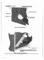
Remove the screws from the top cover.
Remove 2 screws from each end of Uie fill/
siphon port cover See Figure 12. Slide the
top cover forward about 1/2 inch to release it
from the front of the enclosure. Lift top up and
disconnect the sample port tubing. Remove
top from the unit.
For the lower chamber, remove 2 screws from
each end of the lower fill/siphon port cover
See Figure 13. Grasp each end of the cover
and push it down to release the front edge
from the upper splash cover Lift cover out
and remove sample port tubing.
3.10 DOOR HEATERS
1. Disconnect electrical service.
2. Remove 6 screws which fasten door liner to
door. Raise inner edge of gasket to gain
access to screws. Do, not remove screws
completely from gasket; this will aid in
reassembly because screw tips will hold
location of holes in gasket. See Figure 4.
Remove the wire nuts from the heater wires.
Carefully remove heater from top of chamber.
Note the location for replacement purposes.
See Figure 5.
19
5. Remove paper backing from new heater and
apply adhesive side to chamber in same
position: with wires extending in same
direction as faulty heater Be sure all air
pockets are removed when applying new
heater to top of chamber This will over vent
hot spots.
6. Connect the wires as before.
7. Replace all covers.
3.14 OUTER DOOR
CAUTION
BEFORE ATTEMPTING TO REPLACE
AN OUTER DOOR. READ THIS SECTION
THOROUGHLY BE SURE YOU HAVE THE
PROPER TOOLS TO CRIMP A NEW
CONNECTOR ON THE CONTROLLER CABLE.
THE CONNECTOR IS A 20-CONDUCTOR
DEVICE. THE CRIMPING TOOLS WILL BE
MADE AVAILABLE WITH THE DOOR
REPLACEMENT KIT
3.12 FLOAT SWITCHES
1. Disconnect electrical service.
2. For the upper chamber, remove the screws
from the top cover Rennove 2 screws from
each end of the fill/siphpn port cover See
Figure 12. Slide the top cover fonvard about
1/2 inch to release it from the front of the
enclosure. Lift top up and disconnect the
sample port ubing. Remove top from theunit.
3. For the lower chamber, remove 2 screws from
each end of the lower fill/siphon port cover
See Figure 13. Grasp each end of the cover
and push it down to release the front edge
from the upper splash cover Lift cover out
and remove sample port tubing.
3.14.1 SINGLE CHAMBER UNITS
1. Disconnect electrical service. Remove
contents from Incubator chamber. Remove the
shelves. Drain water from water jacket. Refer
to Section 3.17 on controller removal.
2. Remove rear cover. Disconnect Connector J9 from Power board. Remove the controller
cable ground wire from the ground stud. See
Figures 3 & 6.
3. Remove the screws from the top cover.
Remove 2 screws from each end of the fill/
siphon port cover. See Figure 12. Slide Uie
top cover forward about 1/2 inch to release it
from the front of the enclosure. Lift top up and
disconnect the sample port tubing. Remove
top from unit.
4. Remove wire nuts from the float switch wires.
With a thin flat blade screw driver or knofe, 4. Set the unit on its back. Use 3-inch thick
carefully pry Uie float switch mounting bushing
support blocks to rest the unit on.
from the top of the chamber Once the
bushing has come loose, lift the float switch 5. Cut the 4 heater wires (including ground)
out from the top of the chamber See Figure
about 3 inches below the lower door support.
5. Remove paper backing from the washer
These wires will be used again. See Figure
on the new float switch. Replace the float level
14.
switch in the reverse of the above procedure.
6. Cut the controller cable near the upper door
support bracket. Cut this wire only if you are
3.13 INNER GLASS DOOR
replacing the door Remove 4 nuts and bolts
from the upper door support bracket. See
1. Remove the four (4) acorn nuts securing the
Figure 15. Lift bracket and door off unit.
two (2) glass door hinges to chamber face.
7. Route new controller cable through upper door
support bracket. Route the door heater wires
3. Replace glass door in the reverse of the above
through the lower door support bracket.
procedure.
2. Remove the glass door
20
8. Place the door and upper door support bracket 13. Replace the top cover being sure to
back on the unit. Make sure door is square
RECONNECT the sample tube. Replace the
with unit. Attach the upper door support
rear cover. Replace Uie controller
bracket and tighten securely
14. Test the unit for nomfial control function.
9. Cut the new door heater wires about 4 inches
below Uie lower door support. Strip the ends
3.14.2 DUAL CHAMBER UNITS/LOWER
about 3/8 inch. Connect one black wire from
DOOR
tiie new door heater to one oftfieoriginal black 1. Disconnect electrical service. Remove
wires with a wire nut. Repeat this for the other
contents from incubator chambers. Remove
set of black wires with another wire nut
tiie shelves. Drain water from water jackets.
Connect the 2 white wires together with
Refer to Section 3.17 on controller removal.
another wire nut. Finally attach the 2 ground
wires togetiierwiUi a wire nut Secure tiie wires 2. Remove rear cover Disconnect Connector
from physical damage.
J-9 from Power board. Remove the controller
cable ground wire from the ground stud. See
Figures 3 & 6.
10. Set the unit upright There are adjustment
points at Uie upper arid lower door mounting
brackets so that the outer door may be 3. Remove 2 screws from each end of the lower
adjusted to close properiy The outer door
fill/siphon port cover See Figure 13. Grasp
gasket should contact the incubator body
each end of the cover and push it down to
evenly on all four sides. If the door needs
release the front edge from the upper splash
adjustment proceed as follows:
cover Lift cover out and remove sample port
tubing.
a. WiUi a wrench, loosen the two nuts near
the base of the lower door hinge. See 4. Set the unit on it's back. Use 3-inch thick
Figure 14. Do not remove. This will allow
support blocks to rest the unit on.
adjustment of Uie lower section ofthe door
Adjust and tighten as necessary. Do not 5. Cut the 4 heater wires (including ground)
use excessive torque on Uiese nuts.
about 3 inches below the lower door support
for the lower chamber See Figure 14. These
wires will be used again.
b. Loosen the two nuts near the base of the
upper door hinge. See Figure 15. This will
allow adjustment of the upper section of 5. Cut the controller cable near the upper door
support bracket for the lower chamber Cut
the door Adjust andtightenas necessary.
this wire only if you are replacing the door
Again, do not use excessive torque on
Remove 4 nuts and bolts from the upper door
these nuts.
support bracket for the lower chamber See
Figure 13. Lift bracket and door off unit
11. Securely attach the end of the new controller
cable to the end of the old conti'oller cable
and pull the old cable out from the back of tiie 7. Route new controller cable through upper
unit until the new cable, appears.
door support bracket. Route the door heater
wires through the lower door support
bracket.
12. Follow Uie instmctions supplied with the door
replacement kit for proper use of the
installation tools for the 20 pin connector Plug 8. Place the door and upper door support
bracket back on the unit. Make sure door is
the connector back into J-9 on the Power
board. Attach the ground wire to the ground
square with unit. Attach the upper door
stud.
support bracket and tighten securely
21
9. Cut the new door heater wires about 4 inches
below the lower door support. Strip the ends
about 3/8 inch. Connect one black wire from
Uie new door heater to one oftfieoriginal black
wires with a wire nut. Repeat this for the other
set of black wires with another wire nut.
Connect the 2 white wires together with
another wire nut. Finally attach the 2 ground
wires togetfierwiUi a wire hut. Secure the wires
from physical damage,
10.Set the unit upright. There are adjustment
points at the upper and lower door mounting
brackets so that the outer door may be
adjusted to close properiy The outer door
gasket should contact the incubator body
evenly on all four sides. If the door needs
adjustment proceed as follows:
3.14.3 DUAL CHAMBER UNITS/UPPER DOOR
1. Disconnect electrical service. Remove
contents from incubator chamber Refer to
Section 3.17 on controller removal.
2. Remove rear cover. Disconnect Connector
J-9 from Power board. Remove the controller
cable ground wire from the ground stud.
3. Remove the screws from the top cover.
Remove 2 screws from each end of the fill/
siphon port coven See Figure 12. Slide the
top cover fonward about 1/2 inch to release
it from the front of the enclosure. Lift top up
and disconnect the sample port tubing.
Remove top from unit.
4. Remove 2 screws from each end of the lower
fill/siphon port cover See Figure 13. Grasp
each end of the cover and push it down to
release tiie front edge from Uie upper splash
cover Lift cover out and remove sample port
tubing.
a. With a wrench, loosen the two nuts near
Uie base of the lower door hinge. See Figure
14.
Do not remove; This will allow
adjustment of Uie lower section of the door
Adjust and tighten as necessary. Do not use
5. Cut the 4 heater wires (including ground)
excessive torque on thesiB nuts.
about 3 inches below the lower door support
b. Loosen the two nuts near the base of the
for the upper chamber See Figure 13. These
upper door hinge. See Figure 15. This will
wires
will be used again.
allow adjustment of the upper section of the
door Adjust andtightenas necessary. Again,
do not use excessive torque on these nuts. 6. Cut the controller cable near Uie upper door
support bracket for the upper chamber See
Figure 15. Cut this wire only if you are
11 .Securely attach the end of the new controller
replacing the door Remove 4 nuts and bolts
cable to the end of the old conti'oller cable
from the upper door support bracket. Lift
and pull the old cable out from the back of
bracket and door off unit.
Uie unit until the new cable appears.
12.Follow the instructions supplied with the
door replacement kit for proper use of the
instal-lation tools for the 20 pin connector
Plug the connector back into J-9 on the
Power board. Attach the ground wire to the
ground stud.
7. Route new controller cable Uirough upper
door support bracket. Route the door heater
wires through the lower door support
bracket.
8. Place the door and upper door support
bracket back on the unit. Make sure door is
square with unit. Attach the upper door
13. Replace the lower fill/siphon port cover being
support bracket and tighten securely.
sure to reconnect the sample tubing. Replace Uie rear cover Replace the controller.
9. Cut the new door heater wires about 4
inches below the lower door support. Strip
14.Test the unit for normal control function.
the ends about 3/8 inch. Connect one black
wire from the new door heater to one of the
original black wires with a wire nut. Repeat
22
3.15 WATER JACKET CHAMBER
MODULE
tfiis for the oUier set of black virfres witfi anotfier
wire nut. Connect the 2 white wires togeUier
with another wire nut. Finally attach Uie 2
ground wires together with a wire nut. Secure
the wires from physical damage.
3.15.1 SINGLE CHAMBER UNITS
Disconnect electrical service. Remove
contents from incubator chamber. Remove
the shelves. Drain water from water jacket.
Refer to Section 3.1 on shelf support/blower
duct removal, and remove supports and duct.
10.There are adjustment points at the upper
and lower door mounting brackets so that
the outer door may.be adjusted to close
properiy The outer door gasket should contact
the incubator body evenly on all four sides. If
the door needs adjustinent proceed as follows:
Remove rear cover. Remove the cartridge
heaterwires from Connector J-3. Disconnect
Connectors J-4, J-10, J-11 (T/C C02 sensor
units) from Power board. Disconnect the C02
sensor from the interface board (1/R C02
units). Disconnect Uie ground wire from the
fan motor plate. Disconnect the C02
injection and sample port tubing from the
fan motor plate. See Figs. 3, 6 & 7.
a. With a wrench, loosen the two nuts near
the base of Uie lower door hinge, see Figure
14, Do not remove. This will allow
adjustment of the lower section of the door
Adjust and tighten as necessary. Do not use
excessive torque on these nuts.
b. Loosen the two nuts near the base of the
upper door hinge. See Figure 15. This will
allow adjustment of the upper section of the
door. Adjust andtightenas necessary. Again,
do not use excessive torque on these nuts.
Remove the screws from the top cover.
Remove 2 screws from each end of the fill/
siphon port cover See Fig. 14. Slide the top
cover fooArard about 1/2 inch to release it
from the front of the enclosure. Lift top up
and disconnect the sample port tubing.
Remove top from unit Remove the insulation
from the top of the chamber. Disconnect the
auxiliary heater and float switch wires from
the top of the chamber See Figure 5.
11 .Securely attach the end of the new controller
cable to Uie end of the old controller cable
and pull the old cable out from the back of
the unit until the new cable appears.
12.Follow the instructions supplied with the
door replacement kit for proper use of the
instal-lation tools for the 20 pin connector
Plug the connector back into J-9 on the
Power board. Attach the ground wire to the
ground stud.
Set the unit on its back. Use 3-inch thick
support blocks to rest the unit on.
13.Replace the top cover being sure to reconnect the sample tube. Replace the lower
fill/si-phon port cover being sure to reconnect the sample tubing. Replace the rear
cover Re-place the controller.
5. Cut the 4 heater wires (including ground)
about 3 inches below the lower door support.
See Figure 14. These wires will be used
again.
14.Test the unit for normal control function.
Remove 4 nuts and bolts from the upper door
support bracket See Figure 15. Lift bracket
and door off unit. Support the door so as
not to damage the controller cable. Set the
door off to the left side of the unit to allow
clearance for chamber removal.
7. Remove glass door
8. Remove the bolts that secure the splash
cover/lower door support to the unit and
remove. See Figure 13.
23
3.15.2 DUAL CHAMBER UNITS/LOWER
9. Remove tiie nuts (one left and oneright)which
CHAMBER
secure the chamber bottom to the unit's
exterior body. See Figure 14.
1. Disconnect electrical service. Remove
contents from incubator chamber. Remove
the
shelves. Drain water from water jacket.
10. Remove the water jacket chamber module by
Referto
Section 3.1 on shelf support/blower
sliding chamber out of the front of the exteduct
removal,
and remove supports and duct.
rior body These chambers are awkward to
handle and heavy Another person to aid in
removal is advised. If returning chamber to 2. Remove rear cover. Remove the cartridge
heaterwires from Connector J-3. Disconnect
factory for repairs or replacement, remove the
Connectors J-4, J-10, J-11 (T/C C02 sensor
fan motor mounting bracket and float switch.
units) from Power board. Disconnect Uie C02
These items will be used again.
sensor from the interface board (1/R C02
units). Disconnect the ground wire from the
11. Replace water jacket chamber module in
fan motor plate. Disconnect the C02 injection
reverse order of steps 6 through 10 above.
and sample port tubing from the fan motor
plate. See Figs. 3, 6 & 7.
12.There are adjustment points at the upper
and lower door mounting brackets so that
the outer door may be adjusted to close 3. Remove 2 screws from each end of the lower
properly. The outer door gasket should
fill/siphon port cover See Figure 13. Grasp
contact the incubator body evenly on all four
each end of the cover and push it down to
sides. If the door needs adjustment proceed
release the front edge from the upper splash
as follows:
cover/door support. Lift cover out and
remove sample port tubing. Remove the
insulation from the top of the chamber.
a. With a wrench, loosen Uie two nuts near
Disconnect the auxiliary heater and float
the base of tiie lower door hinge. See Figure
switch wires from the top of the chamber.
14. Do not remove. This will allow
See Figure 5.
adjustment of the lower section of the door.
Adjust and tighten as necessary. Do not use
excessive torque on these nuts.
4. Set the unit on its back. Use 3-inch thick
support blocks to rest the unit on.
b. Loosen the two nuts near the base of the
upper door hinge. See Figure 15. This will
allow adjustment of the upper section of the 5, Cut the 4 heater wires (including ground)
about 3 inches below the lower door support.
door Adjust andtightenas necessary. Again,
See Figure 14. These wires will be used
do not use excessive torque on these nuts.
again.
13.Strip the ends of the door heater wires about
3/8 inch. Connect one black wire from the 6. Remove 4 nuts and bolts from the upper door
door heater to one of the cut black wires
support bracket for the lower chamber See
with a wire nut. Repeat this for the other
Figure 13. Lift bracket and door off unit
set of black wires with another wire nut
Support the door so as not to damage the
Connect the 2 white wires together with
con-troller cable. Set the door off to the left
another wire nut. Finally attach the 2 ground
side of the unit to allow clearance for
wires together with a wire nut. secure the
chamber removal.
wires from physi-cal damage.
7. Remove glass door.
14.Complete by reversing steps 1 through 4 of
the above procedure.
8. Remove the bolts that secure the splash
cover/lower door support to the unit and
remove. See Figure 13.
24
9. Remove ttie nuts (one left and one right) which
3.15.3 DUAL CHAMBER UNITSAJPPER
secure the chamber bottom to the units
CHAMBER
exterior body. See Figure 14.
1. Disconnect electrical service. Remove
contents from incubator chamber. Remove
the shelves. Drain water from water jacket
10.Remove the water jacket chamber module
Refer to Section 3.1 on shelf support/blower
by sliding chamber out of the front of the
duct removal, and remove supports and duct
exte-rior body. These chambers are awkward
to handle and heavy Another person to aid
in removal is advised. If returning chamber 2. Remove rear cover. Remove the cartridge
to factory for repairs or replacement, remove
heater wires from Connector J-3. Disconnect
the fan motor mounting bracket and float
Connectors J-4, J-10, J-11 (T/C C02 sensor
switch. These items will be used again.
units) from Power board. Disconnect the C02
sensor from the interface board (l/R C02
units).
Disconnect the ground wire from the
11. Replace water jacket chamber module in
fan
motor
plate. Disconnect the C02 injection
reverse order of steps 6 through 10 above.
and sample port tubing from the fan motor
plate. See Figs. 3, 6 & 7.
12.There are adjustment points at the upper
and lower door mounting brackets so that
the outer door may be adjusted to close 3. Remove the screws from the top cover.
Remove 2 screws from each end of the fill/
properly. The outer door gasket should
siphon port cover. See Figure 12. Slide the
contact the incubator body evenly on all four
top cover forward about 1/2 inch to release
sides. If the door needs adjustinent proceed
it from the front of the enclosure. Lift top up
as follows:
and disconnect the sample port tubing.
a. With a wrench, loosen the two nuts near
Remove top from unit Remove the insulation
the base of the lower door hinge. See Figure
from the top of the chamber Disconnect Uie
14. Do not remove. This will allow
auxiliary heater and float switch wires from
adjustment of the lower section of the door
the top of the chamber See Figure 5.
Adjust and tighten as necessary. Do not use
excessive torque on these nuts.
4. Remove 2 screws from each end of the lower
fill/siphon port cover See Figure 13. Grasp
each end of the cover and push it down to
b. Loosen the two nuts near the base of the
release the front edge from the upper splash
upper door hinge. See Figure 15. This will
cover/door support. Lift cover out and
allow adjustment of the upper section of the
remove sample port tubing.
door Adjust and tighten as necessary. Again,
do not use excessive torque on these nuts.
5. Cut the 4 heater wires (including ground)
about 3 inches below the lower door support
13.Ship the ends of the door heater wires about
for the upper chamber See Figure 13. These
3/8 inch. Connect one black wire from the
wires will be used again.
door heater to one of the cut black wires
with a wire nut. Repeat this for the other
set of black wires with another wire nut 6. Remove 4 nuts and bolts from the upper door
Connect the 2 white wires together with
support bracket See Figure 15. Lift bracket
another wire nut. Finally attach the 2 ground
and door off unit Support the door so as
wires together with a wire nut Secure the
not to damage the contriler cable. Set the
wires from phys-ical damage.
door off to the left side of the unit to allow
clearance for chamer removal.
14.Complete by reversing steps 1 through 4 of
the above procedure.
7. Remove glass door
25
8. Remove the bolts that secure the splash
cover/lower door support to the unit and
remove. See Figure 13.
14. Complete by reversing steps 1 through 4 of
the above procedure.
3.16 FUSES
9. Remove the nuts (one left and one right)
which secure the chamber bottom to the
unit's exterior body. See Figure 14.
1. Disconnect electf-ical service.
2. Pry the fuse holder out of the EMI filter
10.Remove the water jacket chamber module
by sliding the chamber out of the front of
the exterior body. These chambers are
awkward to handle and heavy. Another
person to aid in removal is advised. If
returning chamber to factory for repairs or
replacement, remove the fan motor mouning
backe and float switch. These items will be
used again.
3. Remove fuse(s) in question from fuse holder
4. Locate source of fuse failure before replacing
fuse(s).
5. Replace with new fuse(s) as required.
6. Press fuse holder back in place.
3.17 CONTROLLER BOARD ASSEMBLY
11.Replace water jacket chamber module in
reverse order of steps 6 through 10 above.
12.There are adjustment points at the upper
and lower door mounting brackets so that
the outer door may be adjusted to close
properiy. The outer door gasket should
contact th incubator body eveni on all four
sides. Ifthe door needs adjustment proceed
as follows:
a. With a wrench, loosen the two nuts near
the base of the lower door hinge. See Figure
14. Do not remove, This will allow
adjustment of the lower section of th door
Adjst and tighten as necessary. Do not use
excessive torque on these nuts.
b. Loosen the two nuts near the base of
the upper door hinge. See Figure 15. This
will alow adjustment of the upper section
of the door Ajust and tighten as necessary.
Again, do not use excessive torque on these
nuts.
WARNING
THE CONTROLLER CIRCUIT BOARD CAN BE
EASILY DAMAGED BY STATIC ELECTRICITY.
OBSERVE ALL RULES CONCERNING THE
PROPER HANDLING OF STATIC SENSITIVE
DEVICES. GROUND YOURSELF TO A
KNOWN EARTH GROUNDED METAL OBJECT
IMMEDIATELY BEFORE HANDLING STATIC
SENSITIVE EQUIPMENT
1. Disconnect electrical service.
2. Open the door and remove 2 screws from
the top of the control module. Slide the
controller up and at the same time press
the locking tab in to release the panel. Slide
Uie controller out of the door See Figure 2.
It is best to wrap or lay the board(s) in antistatic bags when handling them out of the
door. Many components used are static
sensitive and can be easily damaged.
13.Strip the ends of the door heater wires about
3/8 inch. Connect one black wire from the
door heater to one of the cut black wires
with a wire nut. Repeat this for the other
set of black wires with another wire nut
Connect the 2 white wires together with
another wire nut. Finally attach the 2 ground
wires together with a wire nut. Secure the
wires from phsical damage.
26
3. Before replacing the controller assembly,
check to see Uiat jumper JP-1 is set to the
OUT" position. JP- 1 is located above U-2.
Next, jumper JP-2 on the controller must be
configured properiy for use with either a T/C
type CO, sensor (Models 5, 5H, 10 or 10), or
for use with an 1/R type CO, sensor (Models
51, 51H. 101 or 101H). JP-2 is located above
U-2. Finally check that jumper JP-3 is set to
the "OUT" position. JP-3 is located to Uie left
of U-2. See Figure 1.
6. Remove the CO, solenoid and bracket
assembly from the board. It will be used on
the replacement board.
4. While holding the locking tab, slide the
conti'oller into the door Be sure the guides
on the control panel are engaged into the
door properly. Push the locking tab back
toward the circuit board so that the controller
can be engaged into the edge card
connector. The locking tab should now spring
forward and be held captive by Uie stud on
the rear of the control panel.
7. Replace power circuit board in reverse order
of above procedure.
NOTE
EVEN THOUGH REPLACEMENT
POWER BOARDS ARE PRE-CALIBRATED AT
THE FACTORY. IT IS RECOMMENDED THE
POWER BOARD VOLTAGES BE CHECKED
AND ADJUSTED AS REQUIRED. REFER TO
SECTION 2.3 REGARDING POWER BOARD
CALIBRATION.
5. Replace Uie controller screws.
3.19 TRANSFORMER
3.18 POWER CIRCUIT BOARD
NOTE
VOLTAGE SELECT JUMPERS FOR
TRANSFORMER AND HEATERS MUST BE
PROPERLY SELECTED BEFORE
ENERGIZING POWER BOARD. FAILURE TO
DO SO MAY DAMAGE POWER BOARD AND/
OR CONTROLLER BOARD.
1. Disconnect electrical service.
2. Remove rear cover.
3. Disconnect Connector J-1 from the power
circuit board. See Figure 3.
4. Remove the mounting screws from the
transformer.
1. Disconnect electrical service.
5. Remove the connector from the old
transformer carefully noting the location of
each wire. The connector will be used on
the replacement transformer
2. Remove rear cover
3. Disconnect Connectors J-1. J-2 J-3, J-4, J8, J-9 J-10 & J-11 from the power circuit
board. Remove the wires from Connectors
J-5 & J-7. Remove ground wire to chassis.
See Figures 3 & 6.
6. Replace ti^nsfonner in reverse order of above
procedure.
3.20 EMI FILTER
4. Remove the mounting screws from the
power circuit board. The power circuit board
may now be removed from the unit.
5. Select the proper transformer tap and voltage
select taps on the Power board. Select the
appropriate COj sensor type used on your
incubator by configuring the IR/TC jumper
Refer to Figure 3.
1. Disconnect electrical service.
2. Remove rear cover
3. Disconnect the wires from the EMI filter.
4. Remove the mounting screws from the EMI
filter and remove filter Remove the fuses
from the old EMI filter. They will be used
again.
5. Replace the EMI filter in reverse order of
above procedure.
27
3.21 REPLACEMENT PARTS LISTS
MODEL 5 (110/120 VOLTS - 50/60 Hz.)
DESCRIPTION
PART NO.
FootLevelers
Power Board Fuse; 3/8 Amp
Fuse: 5 AMP (5 X 20mm)
Blower Duct (Air Plenum)
EMl/RFl Filter
Door Heater
Air Heater
Cartridge Heater
Chamber Heater (Outer Top)
Fan Motor
Solenoid Valve
Limiting Thermostat
Power Transformer
T/C CO, Sensor Assembly
Temperature Sensor Assembly
Blower Wheel
Shelf Slides
CO, Filter (External)
CO, Filter (Internal)
Power Board Assembly
Control Board Assembly
Glass Door
Glass Door Assembly
Float Switch Assembly
Power Cord
Shelf
Water Fill Hose
HEPA Gas Filter
Phone Plug, 1/4" (CMS)
Humidity Tray
241077
101408009
289114
102625010
101432011
247426
247431
143304100
247423
223720
297047
239190
105039087
105028030
105028031
1402-020
102660011
102013005
310128
00374701...
00374902...
330260
107002003.
105013039.
353025
102644010.
108001004.
542575
1418-040....
102633001.
28
STD. QTY.
4
1
2
,
,12
REPUVCEMENT PARTS UST
MODEL 5H (110/120 VOLTS -50/60 Hz.)
DESCRIPTION
PART NO.
FootLevelers
Power Board Fuse; 3/8 Amp
Fuse: AMP (5 X 20mm)
Blower Duct (Air Plenum)
EMl/RFl Filter
Door Heater
Air Heater
Cartridge Heater
Chamber Heater (Outer Top)
Fan Motor
Solenoid Valve
Limiting Thermostat
Power Transformer
T/C CO, Sensor/PC Board Assembly
Temperature Sensor Assembly
Blower Wheel
Shelf Slides
CO, Filter (Extemal)
CO, Filter (Intemal)
Power Board Assembly
Control Panel Assembly
Glass Door
Glass Door Assembly
Float Switch Assembly
Power Cord
Shelf
Water Fill Hose
HEPA Gas Filter Kit
Phone Plug, 1/4" (CMS)
Relative Humidity Sensor Assembly
Humidity Tray
241077
101408009
289114
102625010
101432011
247426
247431
143304100
247423
223720
297047
239190
105039087
105028030
105028031
1402-020
102660011
102013005
310128
00374701...
00374901...
330260
107002003.
105013039,
353025
102644010...
108001004...
542575
1418-040
541951
102633001...
29
STD. QTY.
4
1
2
REPLACEMENT PARTS LISTS
MODEL 51 (110/120 VOLTS - 50/60 Hz.)
DESCRIPTION
PART NO.
FootLevelers
Power Board Fuse; 3/8 Amp
Fuse: 5 AMP (5 X 20mm)
Blower Duct (Air Plenum)
EMl/RFl Filter
Door Heater
Air Heater
Cartridge Heater
Chamber Heater (Outer Top)
Fan Motor
Solenoid Valve
Limiting Thennostat
Power Transfomer
1/R CO, Sensor/PC Board Assembly
Temperature Sensor Assembly
Blower Wheel
Shelf Slides
CO, Filter (External)
CO, Filter (Internal)
Power Board Assembly
Control Board Assembly
Glass Door
Glass Door Assembly
Float Switch Assembly
Power Cord
Shelf
Water Fill Hose
HEPA Gas Filter
Phone Plug, 1/4" (CMS)
Humidity Tray
241077
101408009
289114
102625010
101432011
247426
247431
143304100
247423
223720
297047
239190
105039087
102204101
105028031
1402-020
102660011
102013005
310128
00374701..,
00374902...
330260
107002003.
105013039.
353025
102644010.
108001004.
542575
1418-040....
102633001.
30
STD. QTY.
4
1
2
,12
REPLACEMENT PARTS LIST
MODEL 51H (110/120 VOLTS -50/60 Hz.)
DESCRIPTION
PART NO.
Foot Levelers
Power Board Fuse; 3/8 Amp
Fuse: 5 AMP (5 X 20mm)
Blower Duct (Air Plenum)
EMI/RFl Filter
Door Heater
Air Heater
Cartridge Heater
Chamber Heater (Outer Top)
Fan Motor
Solenoid Valve
Limiting Thermostat
Power Transfomrier
I/R CO2 Sensor/PC Board Assembly
Temperature Sensor Assembly
Blower Wheel
Shelf Slides
CO, Filter (External)
CO, Filter (Internal)
Power Board Assembly
Control Panel Assembly
Glass Door
Glass Door Assembly
Float Switch Assembly
Power Cord
Shelf
Water Fill Hose
HEPA Gas Filter Kit
Phone Plug. 1/4" (CMS)
Relative Humidity Sensor Assembly
Humidity Pan Kit
241077
101408009
289114
102625010
101432011
247426
247431
143304100
247423
223720
297047
239190
105039087
102204101
105028031
1402-020
102660011
102013005
310128
00374701
00374901
330260
107002003
105013039
353025
102644010
108001004
542575
1418-040
541951
102633001
31
STD. QTY.
4
1
2
,12
REPLACEMENT PARTS LISTS
MODEL 10 (110/120 VOLTS - 50/60 Hz.)
DESCRIPTION
PART NO.
FootLevelers
Power Board Fuse; 3/8 Amp
Fuse: 5 AMP (5 X 20mm)
Blower Duct (Air Plenum)
EMl/RFl Filter
Door Heater
Air Heater
Cartridge Heater
Chamber Heater (Outer Top)
Fan Motor
Solenoid Valve
Limiting Thennostat
Power Transformer
T/C CO, Sensor/PC Board Assembly
Temperature Sensor Assembly
Blower Wheel
Shelf Slides
CO, Filter (Extemal)
CO, Filter (Internal)
Power Board Assembly
Control Board Assembly
Glass Door
Glass Door Assembly
Float Switch Assembly
Power Cord
Shelf
Water Fill Hose
HEPA Gas Filter
Phone Plug. 1/4" (CMS)
Humidity Tray
241077
101408009
289114
102625010
101432011
247426
247431
143304100
247423
223720
297047
239190
105039087
105028030
105028031
1402-020
102660011
102013005
310128
00374701
00374902
330260
107002003
105013039
353025
102644010
108001004
542575
1418-040
102633001
32
STD. QTY.
4
2
2
2
1
2
2
4
2
2
2
2
2
2
2
2
24
1
1
2
2
2
2
2
1
10
1
1
2
2
REPLACEMENT PARTS USTS
MODEL 10H (110/120 VOLTS - 50/60 Hz.)
DESCRIPTION
PART NO.
FootLevelers
Power Board Fuse; 3/8 Amp
Fuse: 5 AMP (5 X 20mm)
Blower Duct (Air Plenum)
EMl/RFl Filter
Door Heater
Air Heater
Cartridge Heater
Chamber Heater (Outer Top)
Fan Motor
Solenoid Valve
Limiting Thermostat
Power Transfomier
T/C COj Sensor/PC Board Assembly
Temperature Sensor Assembly
Blower Wheel
Shelf Slides
CO, Filter (External)
CO, Filter (Internal)
Power Board Assembly
Control Board Assembly
Glass Door
Glass Door Assembly
Float Switch Assembly
Power Cord
Shelf
Water Fill Hose
HEPA Gas Filter
Phone Plug. 1/4" (CMS)
Relative Humidity Sensor Assemly
Humidity Tray
241077
101408009
289114
102625010
101432011
247426
247431
143304100
247423
223720
297047
239190
105039087
105028030
105028031
1402-020
102660011
102013005
310128
00374701
00374901
330260
107002003
105013039
353025
102644010
108001004
542575
1418-040
541951
102633001
33
STD. QTY.
4
2
2
2
1
2
2
4
2
2
2
2
2
2
2
2
24
1
1
2
2
2
2
2
1
10
1
1
2
2
2
REPLACEMENT PARTS USTS
MODEL 101 (110/120 VOLTS - 60/60 Hz.)
DESCRIPTION
PART NO.
FootLevelers
Power Board Fuse; 3/8 Amp
Fuse: 5 AMP (5 X 20mm)
Blower Duct (Air Plenum)
EMl/RFl Filter
Door Heater
Air Heater
Cartridge Heater
Chamber Heater (Outer Top)
Fan Motor
Solenoid Valve
Umiting Thermostat
Power Transformer
1/R CO, Sensor/PC Board Assembly
Temperature Sensor Assembly
Blower Wheel
Shelf Slides
CO, Filter (External)
CO, Filter (Internal)
Power Board Assembly
Control Board Assembly
Glass Door
Glass Door Assembly
Float Switch Assembly
Power Cord
Shelf
Water Fill Hose
HEPA Gas Filter
Phone Plug, 1/4" (CMS)
Humidity Tray
241077
101408009
289114
102625010
101432011
247426
247431
143304100
247423
223720
297047
239190
105039087
102204101
105028031
1402-020
102660011
102013005
310128
00374701
00374902
330260
107002003
105013039
353025
102644010
108001004
542575
1418-040
102633001
34
STD. QTY.
4
2
2
2
1
2
2
4
2
2
2
2
2
2
2
2
24
1
1
2
2
2
2
2
1
10
1
1
2
2
REPLACEMENT PARTS USTS
MODEL 101H (110/120 VOLTS - 50/60 Hz.)
DESCRIPTION
PART NO.
FootLevelers
Power Board Fuse; 3/8 Amp
Fuse: 5 AMP (5 X 20mm)
Blower Duct (Air Plenum)
EMl/RFl Filter
Door Heater
Air Heater
Cartridge Heater
Chamber Heater (Outer Top)
Fan Motor
Solenoid Valve
Limiting Thermostat
Power Transformer
l/R CO, Sensor/PC Board Assembly
Temperature Sensor Assembly
Blower Wheel
Shelf Slides
CO, Filter (External)
CO, Filter (Internal)
Power Board Assembly
Control Board Assembly
Glass Door
Glass Door Assembly
Float Switch Assembly
Power Cord
Shelf
Water Fill Hose
HEPA Gas Filter
Phone Plug, 1/4" (CMS)
Relative Humidity Sensor Assemly
Humidity Tray
241077
101408009
289114
102625010
101432011
247426
247431
143304100
247423
223720
297047
239190
105039087
102204101
105028031
1402-020
102660011
102013005
310128
00374701
00374901
330260
107002003
105013039
353025
102644010
108001004
542575
1418-040
541951
102633001
35
STD. QTY.
4
2
2
2
1
2
2
4
2
2
2
2
2
2
2
2
24
1
1
2
2
2
2
2
1
10
1
1
2
2
2
PART 4
ILLUSTRATIONS, FIGURES AND SCHEMATICS
0
Fisher ScieDtific
w.
liH smsox
SB.K^
,1 \ I,"
77
•
•
kfvtMv
IESCTS
'•'Xf
^ \
Figure 1. Control Panel.
TEMP OlSPUY
CAUBAATION ( M )
COaDSPlAY
CAUBRATION (IVS)
SAFETY s e r p o i m CAUBRATION (R-IO)
R.H. DISPLAY
CAUBRATION (R-11)*
PRESS TAB IN TO RELEASE
CONTROUER ASSEMBLY
• NOT USED ON THESE MODELS:
11-687-« 11-687-10
11-887-51
11-687-101
CAUnON
STATIC SE^^smvE DEVICE
Figure 2. Controller Board Removal.
36
SOLENOID VALVE CONNECTOR (J-6)
TR/VNSFORMER CONNECTOR (J-1)
TRANSFORMER INPUT VOLTAGE SELECTOR
FLOAT SWITCH CONNECTOR (J-7)
TEMPERATURE
SENSOR
CONNECTOR
(J-10)
5.1 VOLT VOLTAGE
REGULATOR (U-2)
5.1 v o i r s
ADJUST
(R-10)
I/RCOL
SENSOR
CONNECTO
(J-B)
T/C CO,
SENSOR
NECTOR
^
rail—
'-''•
7.36 VOLTS
ADJUST
(R.9)
RH SENSOR
CONNECTOR
(J-14)
TEMPERATURE
ECORDER (J-12>
HEATER/MOTOR
CONNECTOR (J-4)
AUXILLIARY CHAMBER
HEATER CONNECTOR (J-5)
/"
CO, SOUENOID VALVE
POWER INPUT
CONNECTOR
(J-2)
•HEATER VOLTAGE
SELECTORS
CONTROLLER
MONfTORING
CONNECTOR
JACK (J-13)
\
(J-«)
GROUND WIRE TO CHASSIS GROUND
Figure 3. Power Circuit Board.
UPPER DOOR SUPPORT
WATER-JACKET VENT PORT
WATER-JACKET
FILL/SIPHON PORT
OUTER DOOR GASKET
DOOR UNER
DOOR HEATER
DOOR CUP
COhJTROLLER CABLE
DOOR HEATER WIRES
DOOR GROUND
LOV^'ER DOOR SUPPORT
INSULATION REMOVED FOR CLARmr
Figure 4 . Door Heater a n d A t t a c h i n g C o m p o n e n t s .
37
CO, SAMPLE PORT TUBING
AUXIUARY CHAMBER HEATER
FLOAT SWITCH
CONTROLLER
CABLE
UPPER DOOR SUPPORT BRACKET
Figure 5, Top Cover Removed.
T/C TYPE CO, SENSOR
CO, INLET
/
UMITING THERMOSTAT (AIR HEATER)
AIRHEATERx
I
/
/ TEMPERATURESENSOR CONNECTOR (J-10)
o
/"^NSFORMER
TRANSFORMER
TEMPERATURE
CONNECTOR (J-1)
o
EMI FILTER
AUX. HEATER
CONNECTOR (J-5)
HEATER
CONNECTOR (J-3)
CO, INLET
FAN MOTOR
CO, SAMPLE PORT
HEATER MOTOR
CONNECTOR (J-4)
CHAMBER CARTRIDGE HEATER
T/C CO, SENSOR CONNECTOR (J-11)
Rgure 6. Rear View -> Cover Removed.
38
. 100 WATT AJR HEATER
SPACER FOR BLOWER DUCT
Relative Humidity Sensor
l/R or T/C CO2 SENSOR
UMmNQ THERMOSTAT
C()2 INJECTION PORT
TEMPERATURE SENSOR
a j j SAMPLE PORT
BLOWER WHEEL
MOUNTING NUTS (4)
HEATER MUST BE
STRAIGHT AND PARALLEL
WrrH REAR WALL
Figure 7. Fan Motor Plate.
MOUNTINO SCREWS (3)
^^
Q E N S O R AND SHIELD
IR/TC INTERFACE BOARD
1/R CO2 CABLE AND CONNECTOR
l/R COa CABLE AND
CONNE(DTOR
FUSE
WARNING
ISOUTE FROM
CHASSIS GROUND
CARTRIDGE HEATERS
Figure 8. I/R Interface B o a r d a n d Related C o m p o n e n t s .
39
2. PUa ON SHELF SUDE TO DISENGAGE
FROM BLOWER DUCT
3. FRONT SHELF SUPPORTS CAN NOV/ BE
REMOVED BY UFTINQ UP ON SUPPORT
FRONT SHELF SUPPORT
SHELF SUDE
BLOWER DUCT
UFT UP ON FRONT EDGE OF
SHELF SUDE TO REMOVE
Figure 9. Shelf Slide Removal.
BLOWER DUCT
TURN BLOV/ER DUCT SO n CAN BE BEMOVSD DIAGONAUY
FROM CHAMBER AS SHOWN, BEING CAREFUL NOT TO DAMAGE
DOOR GASKET
Figure 10. Blower Duct Removal.
40
HORIZONTAL KEYWAY
PUCE TOWARD BACK OF CHAMBER
VERTICAL KEYWAY
PWCE TOWARD FRONT OF CHAMBER
Figure 11. Shelf Slide.
REMOVE PROTECTIVE CAP
TOP COVER
SUDE COVER FORWARD TO RELEASE <?OVER FROM THIS EDGE
RLL/SIPHON PORT COVER
SECURING SCREWS (2)
CO2 SAMPLE PORT
Figure 12. Top Cover Removal.
41
UPPER DOOR SUPPORT BRACKET FOR
LOWER CHAMBER (BEHIND COVER)
UPPER SPLASH COVER (ALSO SERVES A3
LOWER DOOR SUPPORT FOR UPPER CHAMBER)
COz SAMPLE PORT
PUSH COVER DOWN TO RELEASE THIS EDGE
FROM UPPER SPLASH COVER
FlLL/SlPHON PORT COVER
Figure 13. Dual Chamber Units - RU/Slphon Port Cover Removal.
NOTE
DOOR ADJUSTMENT NUTS(2)
DOOR ADJUSTMENT NUTS
MAY BE LOCATED ON TOP
OF DOOR SUPPORT
DOOR SUPPORT ATTACHING BOLtS
DOOR HEATER WIRES ' O ' " ^
Figure 14. Lower Door Support.
42
iJofi
DOOR ADJUSTMENT NUTS MAY
BE LOCATED ON BOTTOM OF
DOOR SUPPORT BRACKET
DOOR ADJUSTMENT NUTS
CONTROLER CABLE
UPPER DOOR SUPPORT BRACKET
Figure 15. Upper Door Support Bracket.
43
DOOR SUPPORT BRACKCT
ATTACHMENT BOLTS
W I E : 1 , a M > M £ JU«>BS ON
POKER BQAEO VITH
LINE VOLTAGE.
3 . K S B i TO MXEL MJMeER
FOR UMTS OPTHM.
I
(
^
/non v!v
"
- n o n e • VB.
n m c . mr
uxmc • IB.
IZ>MC-«HI
^O
L ^
• 1 « r a n « u AB S I
(
MKILIAEY t€ATBl
1 .
Jtfl^WJfiXQJMItlll
(OPTIDNAL)
w
—*
llllllli
I
J?5T!7r
«r
Me
n
'
L ^ ^ J
_^»»».»»T
(OPTIONAL >
HMOITY
Mri
m
=&Q a
^•g
•Sim
-•i^?LIMITING
TIOWOSTAT
m€i>f• _
_
-
^
—
—
• - * « * * » > "
- • 1 ^
mnsn. o a . c
|_
TCCajSHSO!
emwn
_|
sw
^
(OPTIONAL >
I
TC CD} SBGOR
l/CCD,
In
LiV m , PCB
(OPTIONAL)
WIRING DIAGRAM
(P/N 541950)
O
owniaz
ICATB5
i_
J
]/S EH} P ^
<BKioia_
_|