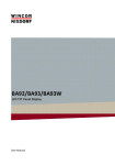
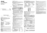
1
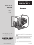
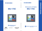
Back
MULTI-PURPOSE LCD DISPLAY
MU-151C
Your Local Agent/Dealer
9-52 Ashihara-cho,
Nishinomiya 662-8580, JAPAN
Telephone :
0798-65-2111
fax
0798-65-4200
:
All rights reserved.
Printed in Japan
PUB.No. OME-20320
( YOTA ) MU-151C
FIRST EDITION : JUL . 2004
*00014999200*
*00014999200*
*00014999200*
*OME20320A00*
*OME20320A00*
*OME20320A00*
IMPORTANT NOTICE
•
No part of this manual may be copied or reproduced without written permission.
•
If this manual is lost or worn, contact your dealer.
•
The contents of this manual and equipment specifications are subject to change without
notice.
•
The example screens (or illustrations) shown in this manual may not match the screens
you see on your display. The screen you see depends on your system configuration and
equipment settings.
•
This manual is intended for use by native speakers of English.
•
FURUNO will assume no responsiblity for the damage caused by improper use or
modification of the equipment or claims of loss of profit by a third party.
SAFETY INSTRUCTIONS
Safety Instructions for the Operator
Safety Instructions for the Installer
WARNING
WARNING
Do not open the equipment.
Do not open the cover
unless totally familiar with
electrical circuits and
service manual.
Only qualified personnel
should work inside
the equipment.
Improper handling can result
in electrical shock.
Do not disassemble or modify the
equipment.
Fire, electrical shock or serious injury can
result.
Turn off the power at the switchboard
before beginning the installation.
Use the proper fuse.
Fire or electrical shock can result if the
power is left on.
Fuse rating is shown on the equipment.
Use of a wrong fuse can result in damage
to the equipment.
Do not install the equipment where it
may get wet from rain or water splash.
Immediately turn off the power at the
switchboard if the equipment is emitting
smoke or fire.
Water in the equipment can result in fire,
electrical shock or damage to the equipment.
Continued use of the equipment can cause
fire or electrical shock. Contact a FURUNO
agent for service.
CAUTION
Ground the equipment to
prevent mutual interference.
A warning label is attached to the
equipment. Do not remove the label.
If the label is missing or damaged,
contact a FURUNO agent or dealer.
WARNING
To avoid electrical shock, do not
remove cover. No user-serviceable
parts inside.
Observe the following compass safe
distances to prevent interference to a
magnetic compass:
Name: Warning Label (1)
Type: 86-003-1011-1
Code No.: 100-236-231
MU-151C
Standard
compass
Steering
compass
0.45 m
0.30 m
The surface of the LCD monitor is made
of glass. Handle it with care.
About the TFT LCD
The TFT LCD is constructed using the
latest LCD techniques, and displays
99.99% of its pixels. The remaining 0.01%
of the pixels may drop out or blink, however this is not an indication of malfunction.
When lifting the display unit, hold it
together with the hardcover.
Grasping by the hardcover alone may allow
the display unit to fall, resulting in
possible injury or damage to the equipment.
i
TABLE OF CONTENTS
FOREWORD ........................................................................................................ iii
SYSTEM CONFIGURATION................................................................................ iv
EQUIPMENT LISTS .............................................................................................. v
1 MOUNTING ...................................................................................................... 1
1.1 Display Unit ..................................................................................................................... 1
2 WIRING............................................................................................................. 5
2.1 Wiring.............................................................................................................................. 5
3 ADJUSTMENTS ............................................................................................... 7
3.1 Menu Settings ................................................................................................................. 7
3.2 Low Brilliance Setting and Brilliance Control Mode........................................................ 10
4 OPERATION ................................................................................................... 11
5 MAINTENANCE, TROUBLESHOOTING....................................................... 12
5.1 Maintenance.................................................................................................................. 12
5.2 Troubleshooting............................................................................................................. 13
SPECIFICATIONS........................................................................................... SP-1
PACKING LISTS ............................................................................................... A-1
OUTLINE DRAWINGS ...................................................................................... D-1
INTERCONNECTION DIAGRAM ......................................................................S-1
ii
FOREWORD
A Word to the Owner of the MU-151C
FURUNO Electric Company thanks you for purchasing the MU-151C 15” Multi-Purpose
LCD Display. We are confident you will discover why the FURUNO name has become
synonymous with quality and reliability.
For over 50 years FURUNO Electric Company has enjoyed an enviable reputation for
quality and reliability throughout the world. This dedication to excellence is furthered by our
extensive global network of agents and dealers.
Your equipment is designed and constructed to meet the rigorous demands of the marine
environment. However, no machine can perform its intended function unless properly
installed and maintained. Please carefully read and follow the operation, installation and
maintenance procedures set forth in this manual.
We would appreciate feedback from you, the end-user, about whether we are achieving our
purposes.
Thank you for considering and purchasing FURUNO.
Features
• Main or remote display for radars, video sounders, sonars. Compatible equipment:
FR-1500 MK3 series, FCV-1200L/LM, FCV-1500L, CH-250, CH-270, CSH-5L/8L,
GD-280/380/680, etc.
• High resolution display of 1024x768 dot (XGA), 640x480 dot (VGA)
• Brightness of 350 cd/m2 and minimum 250 cd/m2 for comfortable viewing day and night
• Landscape orientation
• Wide viewing angle for observation by more than one person
iii
SYSTEM CONFIGURATION
RGB
Radar, Video Plotter,
Navigator, Video Sounder,
Scanning Sonar, etc.
Control sig.
12-24 VDC or
100-220 VAC
NMEA 0183
Control unit of
Video Sounder*
(e.g., FCV-1200L/LM)
Navigator (GPS, etc.)
* = When connecting the FCV-1200L/LM,
CH-250 or CH-270 as the main display unit,
connect it to the MU-151C instead of the
interface unit.
Connectable equipment
Equipment
Resolution*
FR-1500 MK3 series
XGA
FCV-1200L/LM
VGA
FCV-1500L
VGA
GD-280/380/680
VGA
CH-250
VGA
CH-270
VGA
CSH-5L/8L
XGA
CI-68/88
VGA
*: VGA: 640x480 dot, XGA: 1024x768 dot
Note: Portrait orientation equipment cannot be connected to the MU-151C.
Note: There are two ports for video signal, but they cannot be used simultaneously.
iv
EQUIPMENT LISTS
Standard supply
Name
Type
LCD Display Unit
Code No.
Qty
−
1
MU-151C
Remarks
DC specification
AC specification
SP19-00101
001-403-170
SP06-01301
001-403-800
CP19-00100
000-012-630
CP06-01400
000-012-637
FP19-00801
001-410-510
1 set
Without hanger
FP19-00702
008-540-740
1 set
With hanger
Type
Code No.
Qty
3COX-2P-6C 5M
000-146-500
1
Cable length: 5 m
3COX-2P-6C 10M
000-146-501
1
Cable length: 10 m
Hanger Kit
FP19-00900
001-410-540
1
w/knob, self-tapping screws
Hood Kit
FP06-01301
001-403-820
1
Spare Parts*
Installation Materials*
Accessories*
1 set
1 set
For DC
For AC
For DC
(MJ-A3SPF0025-035)
For AC (CP06-01401)
Option
Name
Cable Assy
* = See packing list at the end of this manual.
v
Remarks
1 MOUNTING
Refer to the outline drawing at the end of this manual for mounting dimensions.
Note: The surface of the LCD monitor is made of glass. Handle it with care.
1.1 Display Unit
The display unit may be mounted on a desktop or flush mounted in a panel.
When selecting a mounting location, keep in mind the following points:
• Locate the unit out of direct sunlight.
• Select a location where the display can be easily viewed and the controls can be easily
operated.
• Leave sufficient space around the unit for servicing and maintenance. See the outline
drawing for minimum servicing space.
• The unit weighs approximately 7.5 kg (flush mounting)/8.5 kg (desktop mounting). Be
sure the mounting location is strong enough to support the weight of the unit.
• Locate the unit away from areas subject to water splash and rain.
1
Flush mounting
See the outline drawing at the end of this manual for mounting dimensions.
CAUTION
Hold the hard cover and display unit
together when lifting the display unit.
The display unit may fall if only the
hard cover is held.
1. Remove the hard cover from the unit.
2. Using the paper template supplied in the installation materials, make a cutout in the
mounting location.
3. Set the display unit to the cutout, and fasten it with four self-tapping screws (5x40,
supplied as accessories).
Note: Hex head bolts may also be used to fasten the display unit. However, their lengths
must be 10 mm longer than the wall thickness.
130
30
Panel cover
Waterproofing property: IP20
Waterproofing property: IP25
Mounting dimensions
4. Attach the panel cover (supplied as accessories) to the display unit at the locations
shown in the drawing above.
5. Attach the hard cover to protect the LCD.
Note: If necessary, coat gap between the mounting panel and the display unit chassis with
sealing material.
2
Desktop mounting
The display unit with hanger can be mounted on a desktop. If you purchased the unit
without hanger, order the optional hanger kit (Type: FP19-00900, Code No.: 001-410-540).
Contents of hanger kit
Name
Hanger
Knob bolt
Self-tapping screw
Type
FP19-00901
FP03-09204
5x20
Code No.
001-410-550
008-523-650
000-802-081
Qty
1
2
4
Mounting procedure
1. Fasten the hanger to the mounting location with four self-tapping screws (supplied).
2. Screw knob bolts into the hanger, set the unit to the hanger, and tighten the knob bolts.
3. Attach the hard cover to protect the LCD.
Knob bolt
Hanger
Desktop mounting
3
Hood (option)
When it is too bright in the daytime, use the optional hood kit (Type: FP06-01301, Code No.:
001-403-820) to shade the screen.
Contents of hood kit
Name
Hood
Fixing plate
Cosmetic screw
Upset screw
Hex nut
Flat washer
Spring washer
Type
06-024-2402
06-024-2403
M3x6
M5x25
M5
M6
M6
Code No.
100-320-460
100-320-471
000-150-356
000-808-427
000-863-108
000-864-129
000-864-260
Qty
1
4
4
4
4
4
4
1. Desktop mounting: Fasten the fixing plates to the fixing holes with four upset screws
(supplied), four flat washers (supplied), four spring washers (supplied) and four hex nuts
(supplied).
Flush mounting: Fasten the display unit to the mounting location, and then attach the
fixing plates with four self-tapping screws.
Upset screw
Fixing plate
Spring washer
Flat washer
Fixing hole
Hex nut
2. Attach four panel covers (supplied as accessories) to the display unit.
3. Locate the hood over the display unit (the hood is outside of the fixing plates).
4. Fasten the hood to the fixing plates with four cosmetic screws (supplied).
4
2 WIRING
2.1 Wiring
Connect equipment to the MU-151C by referring to the drawings in this section and the
interconnection diagram at the back of this manual. A cable with a connector at both ends is
provided to connect equipment.
General-purpose monitor
To use the MU-151C as a general-purpose monitor, connect equipment with the optional
cable assy, 3COX-2P-6C (5 or 10 m). In this case do not connect a navigator to the NMEA
port. Nav data is output through the D-SUB 25P connector.
12-24 VDC (MJ-A3SPF0025-035, 3.5 m)
or 100-220 VAC (DPYCY-1.5*)
Ground Terminal
RGB IN port
FCV-1200L/1200LM: INTERFACE UNIT RGB OUT port
CH-250, CH-270: INTERFACE UNIT RGB OUT port
GD-280/380/680:DISPLAY UNIT EXT VIDEO port
CSH-5L/8L: PROCESSOR UNIT
3COX-2P-6C
(5/10 m)
MONITOR1 or MONITOR2 port
FR-1500 MARK-3: Connector on RGB BUFFER board in the display unit
CI-68/88: Connect to CN-A1 port in the control unit with the conversion cable
(66S1242, 0.3 m)
Note: Even when the power switch is off, the electric current flows slightly. Connect the
power line via a double-contact breaker.
Note: If one line of AC is grounded, connect one line to the “C” (Common) terminal and the
other line to the “H” (Hot) terminal.
*: Solder connector SRCN6A13-3S (supplied in installation materials) to the power
cable (DPYCY-1.5 (Japan Industrial Standard) or equivalent).
4-6 cm
3m
DPYCY-1.5
m
Armor
Solder Side
Screw
Sheath Armor
12
Clamp Tighten
3
set screw
Connect to
"1" and "2".
Connector Housing
1: AC (H: Hot)
2: AC(C: Cold)
5
Sheath
φ = 11.7 mm
Conductor
S = 1.5 mm 2
φ = 1.56 mm
Connecting FCV-1200L/1500L or CH-250/270
CONT port
NMEA port
12-24 VDC (MJ-A3SPF0025-035, 3.5 m)
or 100-220 VAC (DPYCY-1.5)
Ground Terminal
Navigator, etc.
DATA/VIDEO IN port
FCV-1200L/1200LM: CONTROL UNIT CONT port
FCV-1500L: CONTROL UNIT CONT port
MJ-A10SPF0002-015
CH-250, CH-270: CONTROL UNIT CONT port
06S4078
FCV-1200L/1200LM: CONTROL UNIT CONT port
FCV-1500L: PROCESSOR UNIT CN1 port
CH-250, CH-270: TRANSCEIVER UNIT
DATA/VIDEO OUT port
•
The cover of the D-sub connector of the cable 06S4078 may be removed to pass the
cable through tubing, bulkhead, etc. Use vinyl tape to bind connector wiring and rubber
cover. This allows the cable to be passed through a hole having a diameter of 30 mm.
•
Cable 06S4078 is of waterproof construction, however, the rear panel of the MU-151C is
not waterproof (specification IP20). Therefore, remove rubber cover and fixing metal
from the display unit side of the cable.
Remove fixing metal.
Remove rubber cover.
6
3 ADJUSTMENTS
3.1 Menu Settings
The menu contains items for adjustment of the display.
1. Press the [MENU] key to show the menu.
2. Choose XGA or VGA at “Resolution” at the top of the menu depending on the equipment
connected (see page iv).
XGA
255
127
61
52
39
255
255
255
Resolution
Contrast
H Total
Phase
H Position
V Position
ContrastRed
ContrastGrn
ContrastBlu
AutoAdjust
AutoColor
Default
Main menu
3. Press [▼] to select [Default], and then press the [MENU] key.
”Default” is usually used to restore default settings; however, execute it at this time.
4. Execute the [AutoAdjust], referring to page 9.
5. Execute the [AutoColor], referring to page 9.
6. If necessary, press [▲] or [▼] to select the menu item you want to adjust, and then
press [◄] or [►] to adjust.
7. Press the [MENU] key to close the menu.
7
Contents of menu item
Menu item
Contrast
H Total
Phase
H Position
V Position
ContrastRed
ContrastGrn
ContrastBlu
AutoAdjust
AutoColor
Default
Function
Increases or decreases contrast level.
Adjusts the gain value of RGB together.
Adjusts the image size horizontally.
If the setting value is inappropriate too much,
nothing may appear on the screen.
Adjusts the characters and graphic lines.
Moves the image position horizontally.
Moves the image position vertically.
Adjusts red color contrast.
Adjusts green color contrast.
Adjusts blue color contrast.
Adjusts timing automatically for H Total, Phase,
H Position and V Position.
Increases or decreases contrast level automatically.
Initializes settings.
When nothing or “AutoAdjust ERROR” appears on
the screen in adjusting, select [Default] and press
the [MENU] key.
Available range
0-255
0-127
0-61
0-255
0-255
0-255
AutoAdjust and AutoColor may not function depending on equipment connected. Refer to
the table below.
Equipment
FCV-1200L/LM
FCV-1500L
CH-250
CH-270
CSH-5L/8L
CI-68/88
GD-280/380/680
FR-1500 MARK-3 series
AutoAdjust
Yes
Yes
Yes
Yes
Yes
Yes
No
Yes
8
AutoColor
Yes
Yes
Yes
Yes
Yes
Yes
Yes
No
AutoAdjust
1. Operate the external equipment connected to the MU-151C to show the frame test
pattern. Refer to each manual for how to show the test pattern.
AutoAdjust is inoperative if the frame test pattern is not available. In this case, adjust the
timing manually.
Frame test pattern
2. Press the [MENU] key on the MU-151C.
3. Press [▲] or [▼] to select [AutoAdjust], and then press the [MENU] key.
“OK” or “ERROR” appears on the screen after a few seconds.
When “OK” appears, confirm that the corners of the frame are placed in respective
corners on the screen. If the frame is misaligned or “ERROR” appears, adjust the H
Total, H Position and V Position manually.
Confirm that small characters are shown clearly. If not, adjust the Phase.
AutoColor
1. Operate the external equipment connected to the MU-151C to show the white test
pattern. Refer to each manual for how to show the test pattern.
AutoColor is inoperative if the white test pattern is not available. In this case, adjust the
contrast manually.
White
White test pattern
2. Press the [MENU] key on the MU-151C.
3. Press [▲] or [▼] to select [AutoColor], and then press the [MENU] key.
“OK” or “ERROR” appears on the screen after a few seconds.
If “ERROR” appears, adjust the Contrast manually, observing the screen. When there is
a great difference in the contrast level among red, green and blue, adjust ContrastRed,
ContrastGrn and ContrastBlu.
9
3.2 Low Brilliance Setting and Brilliance Control Mode
Low brilliance is adjusted with the DIP switch (S1) on the CON board (06P0265). Brilliance
control mode is selected with the slide switch (S2). Two control modes are available:
internal and external. These switches are on the left side of the rear panel of the display unit.
Remove the round cap from the connector mounting plate to access the switches.
BRIL
2
0
2
1
2
2
AUX2
ON
S1
OFF
1
2
3
EXT
Low Brilliance Setting
4
INT
Brilliance Control Mode
S2
Low brilliance setting (S1 switch)
Adjust the display brilliance on low brilliance.
0
2
OFF
ON
OFF
ON
OFF
ON
OFF
ON
DIP switch
21
OFF
OFF
ON
ON
OFF
OFF
ON
ON
22
OFF
OFF
OFF
OFF
ON
ON
ON
ON
Setting value
0
1
2
3
4
5
6
7
• Usually the MU-151C is operated on default setting (setting value of the DIP switch is
indeterminate).
• The default brilliance with the brilliance control 1 (second lowest setting) is 0.3 cd/m2.
• If the display brilliance as 1 is too bright at night, decrease the brilliance level with the DIP
switch.
• If the display brilliance as 1 is too dark at night, increase the brilliance level with the DIP
switch.
• If the maximum level of the brilliance (10) is same regardless of the setting on the DIP
switch.
Brilliance control mode (S2 switch)
• Usually the MU-151C is operated using the default brilliance mode setting (“INT” (internal)).
The display brilliance is adjusted with the [BRILL] key on the MU-151C.
• With the CH250/270 or FCV-1200L/1500L the display brilliance is adjusted from their
control unit. Set the control mode for “EXT” (external). The [BRILL] key on the MU-151C
is inoperative.
10
4 OPERATION
Arrow keys
MENU
ESC
S
S
S
Power key
S
LED
Brill key
Key/LED
Function
Turns the power on/off.
Adjusts the display brilliance (lowest: 0, highest: 10).
-: Decreases the display brilliance.
+: Increases the display brilliance.
MENU
Opens/closes the main menu.
ESC
Escapes from current screen.
Arrow keys (▲)(▼) Selects menu items.
Arrow keys (◄)(►)* Adjusts settings.
LED
Changes color according to signal status as below.
Green: The selected signal is input from the external device.
Orange: The selected signal is not input from the external device.
*: These keys may be pressed and held down to change setting faster.
Note: Even if the power switch is off, electricity flows through the equipment. Won’t be used
for a long time, turn off the breaker switch at ship’s power distribution box. This is
especially important for DC equipment to avoid battery consumption.
11
5 MAINTENANCE,
TROUBLESHOOTING
WARNING
ELECTRICAL SHOCK HAZARD
Do not open the equipment.
Only qualified personnel
should work inside the
equipment.
5.1 Maintenance
Routine maintenance
Regular maintenance is important for good performance. Check the following on a regular
basis to keep the equipment in good operating condition.
• Check that the connectors at the rear of the display unit are tightly fastened.
• Check the ground wire and ground terminal for rust. Clean if necessary. Confirm that the
ground wire is tightly fastened.
• Remove dust and dirt from the display unit and LCD with a dry, soft cloth. Do not use
chemical cleaners to clean any part of the display unit – they can remove paint and
markings.
• Wipe the LCD carefully to prevent scratching, using tissue paper and an LCD cleaner. To
remove dirt or salt deposits, use an LCD cleaner, wiping slowly with tissue paper so as
to dissolve the dirt or salt. Change paper frequently so the salt or dirt will not scratch the
LCD. Do not use solvents such as thinner, acetone or benzene for cleaning.
Fuse replacement
The 4 A fuse (AC spec.) or 7 A fuse (DC spec.) on the rear panel or in the power cable
protects the equipment from internal fault and overcurrent. If the fuse blows, find the cause
before replacing it. If the fuse blows again after replacement, request service.
WARNING
Use the proper fuse.
Use of a wrong fuse can cause fire or
damage to the equipment.
12
5.2 Troubleshooting
The table below provides troubleshooting procedures to use when no picture appears. If
you cannot restore the picture, do not attempt to check inside the equipment – there are no
user serviceable parts inside. Refer any work to a qualified technician.
Troubleshooting table
Reason for no picture
Remedy
Battery voltage too high.
Check battery voltage.
Fuse has blown.
Replace fuse (AC: on the
rear of the display unit, DC:
in the power cable).
Cable between MU-151C and external
equipment has loosened.
Refasten cable.
Power cable has loosened.
Refasten cable.
The brilliance is too low.
Increase the brilliance.
13
FURUNO
MU-151C
SPECIFICATIONS OF MULTI-PURPOSE LCD DISPLAY
MU-151C
1
GENERAL
1.1
Display
15-inch XGA color TFT-LCD, 304x228 mm
1.2
Brightness
350 cd/m 2 typical, 250 cd/m 2 minimum
1.3
Resolution
XGA (1,024x768), Magnified for VGA
1.4
Viewing Angle
up: 75°, down: 65°, left/right: 80°
1.5
Input Signal
RGB port: VESA (VGA, XGA)
(1.0 Vp-p (0.7 Vp-p is also possible), Synchronization: TTL level)
2
POWER SUPPLY
2.1
Rated Voltage
100-220 VAC: 0.5 A, 1Φ, 50-60 Hz
or
12-24 VDC, 4.0-2.0 A
3
ENVIRONMENTAL CONDITION
3.1
Ambient Temperature
Display unit: -15°C to +55°C, Storage: -20°C to +60°C
3.2
Relative Humidity
93% at 40°C
3.3
Waterproofing
Display unit front panel: IP25
(IEC 60529)
Display unit rear panel: IP20
Vibration
● 2 - 5 Hz and up to 13.2 Hz with an excursion of ±1 mm ±10%
3.4
(IEC 60945 ed.4)
(7 m/s2 maximum acceleration at 13.2 Hz)
● 13.2 - 100 Hz with a constant maximum acceleration of 7 m/s2
4
COATING COLOR
4.1
Display Unit
N3.0
SP - 1
E2032S01A
Y. Hatai
D-1
Y. Hatai
D-2
Y. Hatai
D-3
Y. Hatai
D-4
C
B
A
1
2
3
4
5
6
7
8
9
10
DPYCY-1.5
*1
12-24 VDC MJ-A3SPF0025-035,3.5m
100-220 VAC
1φ,50-60Hz
*4
FUSE
7A
*3
MJ-A6
SPFD
*3
MJ-A10
SPFD
2
*3
MJ-A3SPFD
SRCN6A13-3S
*2
MJ-A10SPF0002
1.5/5m,φ8.9
*2
MJ-A6SPF0012,6P-6P
MJ-A6SPF0011,6P-4P
5/10m,φ6.1
*3
MJ-A10
SPFD
注記
*1)造船所手配。
*2)オプション。
*3)工場にて取付済み
*4)交流電源の片方がアースに落ちている場合は、そのラインを
C(コモン)端子に接続し、他方はH(ホット)端子に接続します。
NOTE
*1. SHIPYARD SUPPLY.
*2. OPTION.
*3. FITTED AT FACTORY.
*4. IF ONE LINE OF AC IS GROUNDED, CONNECT IT TO
"C" (COMMON) TERMINAL AND THE OTHER LINE TO "H" (HOT).
DC仕様
DC SPEC
AC仕様
AC SPEC
CH-250/270,FCV-1500L用
FOR CH-250/270,FCV-1500L
IEC 61162-1
(NMEA0183)
航法装置
NAVAID
TRXTD_A
TRXTD_B
CONTD_A
CONTD_B
PSW_H
PSW_C
+12V
GND
SCAN_REV
FG
CONT
操作部 CONTROL UNIT
CH-252(CH-250/270)
CV-1501(FCV-1500L)
1
1
2
3
1
2
3
1
2
3
4
5
6
1
2
3
4
5
6
7
8
9
10
*1
IV-8SQ
DC仕様
DC SPEC
AC仕様
AC SPEC
1
2
3
4
5
6
7
8
9
10
11
12
13
14
15
1
2
3
4
5
6
7
8
9
10
11
12
13
14
15
16
17
18
19
20
21
22
23
24
25
DWG.No.
APPROVED
CHECKED
C2032-C01- A
1
2
3
4
5
6
7
8
9
10
11
12
13
14
15
16
17
18
19
20
21
22
23
24
25
*3
D-SUB15P
*3
XM2A-2501
3COX-2P-6C *2
5/10m,φ8.5
*2
06S4078
5/10m,φ12
K.MIYAZAWA
*3
D-SUB15P
*3
XM2A-2501
TAKAHASHI.T
Jul. 9 '04
DRAWN
RED
GREEN
BLUE
NC
GND
GND
GND
GND
NC
GND
NC
NC
HSYNC
VSYNC
NC
RGB IN
R
G
B
HS_N
VS_N
YC_N
TRXTD_A
CONTD_A
TD_A
RD_A
PSW_H
12VA
0V
R_GND
G_GND
B_GND
HS_N_GND
VS_N_GND
YC_N_GND
TRXTD_B
CONTD_B
TD_B
RD_B
PSW_C
12VA
DATA/VIDEO IN
*1
IV-8SQ
保護アース PE
+
GND
12-24 VDC
H
C
100-220 VAC
TD_A
TD_B
RD_A
RD_B
NC
GND
NMEA
TRXTD_A
TRXTD_B
CONTD_A
CONTD_B
PSW_H
PSW_C
+12V
GND
SCAN_REV
FG
CONT
LCD表示器
LCD DISPLAY
MU-151C
3
NAME
名 称
TITLE
INTERCONNECTION DIAGRAM
MULTI-PURPOSE LCD DISPLAY
相互結線図
MU-151C
15型カラーLCD表示器
ECHO SOUNDER
SONAR
RADAR
PLOTTER
魚群探知機
ソナー
レーダー
プロッタ
制御部
PROCESSOR UNIT
CV-1503(FCV-1500L)
送受信装置
TRANSCEIVER UNIT
CH-253(CH-250)
CH-273(CH-270)
(CV-1503)
R
G
B
HS_N
VS_N
YC_N
TRXTD_A
CONTD_A
TD_A
RD_A
PSW_H
12VA
0V
R_GND
G_GND
B_GND
HS_N_GND
VS_N_GND
YC_N_GND
TRXTD_B
CONTD_B
TD_B
RD_B
PSW_C
12VA
CN1
DATA/VIDEO OUT (CH-253/273)
4
S-1