1
DUAL-FREQUENCY SEARCHLIGHT SONAR
CH-300
www.furuno.co.jp
The paper used in this manual
is elemental chlorine free.
・FURUNO Authorized Distributor/Dealer
9-52 Ashihara-cho,
Nishinomiya, 662-8580, JAPAN
Telephone : +81-(0)798-65-2111
Fax
: +81-(0)798-65-4200
All rights reserved.
Printed in Japan
A : APR . 2005
B : SEP . 07, 2007
Pub. No. IME-13250-B
(YOSH )
CH-300
*00015190211*
*00015190211*
* 0 0 0 1 5 1 9 0 2 1 1 *
SAFETY INSTRUCTIONS
WARNING
WARNING
Install the specified transducer tank
in accordance with the installation
instructions. If a different tank is to be
installed the shipyard is solely responsible for its installation, and it should
be installed so the tank doesn't strike
an object.
ELECTRICAL SHOCK HAZARD
Do not open the equipment.
Only qualified personnel
should work inside the
equipment.
Turn off the power at the switchboard
before beginning the installation.
The tank or hull may be damaged if the
tank strikes an object.
Fire or electrical shock can result if the
power is left on.
If a steel tank is installed on a wooden
or FRP vessel, take appropriate
measures to prevent electrolytic
corrosion.
Do not install the equipment where it
may get wet from rain or water splash.
Electrolytic corrosion can damage the hull.
Water in the equipment can result in fire,
electrical shock or damage to the
equipment.
Be sure that the power supply is
compatible with the voltage rating of
the equipment.
Be sure no water leaks in at the transducer installation site.
Connection of an incorrect power supply
can cause fire or damage to the equipment.
The voltage rating of the equipment appears
on the label above the power connector.
Water leakage can sink the vessel.
Also confirm that the transducer will not
loosen by ship's vibration.
The installer of the equipment is solely
responsible for the proper installation of the
equipment. FURUNO will assume no
responsibility for any damage
associated with improper installation.
i
CAUTION
CAUTION
Ground the equipment to
prevent electrical shock and
mutual interference.
WORKING WITH THE SONAROIL
Precautions
Keep oil away from eyes. Wear protective
gloves when working with the oil. The oil
can cause inflammation of the eyes.
Observe the following compass safe
distances to prevent deviation of a
magnetic compass:
Standard
Do not touch the oil. Wear protective
gloves when working with the oil. The oil
can cause inflammation of the skin.
Steering
CH-302/
MU-100C
0.80 m
0.55 m
CH-303
0.55 m
0.30 m
IF-8000
0.95 m
0.65 m
CH-302
0.30 m
0.30 m
CH-256
0.30 m
0.30 m
Do not ingest the oil. Diarrhea or vomiting
can result.
Keep the oil out of reach of children.
Emergency
If the oil enters eyes, flush with clean
water about 15 min. Consult a physician.
Install the monitor unit MU-100C out of
direct sunlight.
If the oil contacts skin, wash within soap
and water.
It is difficult to see the display in direct
sunlight.
If the oil is ingested, see a physician
immediately.
Keep hands away from the raise/lower
shaft of the hull unit when it is working.
Disposal of oil and its container
Dispose of oil and its container in
accordance with local regulations.
For further details, contact place of
purchase.
Injury to hands may result if they become
caught in the shaft.
Do not exceed 20 knots when operating
the equipment and do not exceed 15
knots when raising or lowering the
transducer.
Storage
Seal container to keep out foreign
material. Store in dark place.
The transducer shaft may become
damaged.
The hull unit is designed to withstand ship's
speed of 20 knots. For vessel with greater
speed, reinforce the hull unit.
The transducer tank should be mounted at
the place above the waterline. If this is
impossible, make safety provisions (ex.
construction of watertight compartment).
If there is a possibibility of vibration at the
soundome in high-speed cruising, which
creates prssure inside the tank, discuss the
problem with shipyard and hull manufacturer.
ii
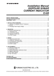
TABLE OF CONTENTS
SYSTEM CONFIGURATION ·······················································································iv
EQUIPMENT LISTS ····································································································v
1. MOUNTING ·············································································································1-1
1.1 Monitor Unit/Control Unit ............................................................................................................1-1
1.2 Control Unit .................................................................................................................................1-5
1.3 Transceiver Unit ..........................................................................................................................1-7
1.4 Hull Unit ......................................................................................................................................1-8
1.5 Interface Unit...............................................................................................................................1-22
1.6 Motion Sensor MS-100 (option).................................................................................................1-23
1.7 Clinometer BS-704 (option) .......................................................................................................1-24
2. WIRING ···················································································································2-1
2.1 Wiring Among Units ....................................................................................................................2-1
2.2 Transceiver Unit ..........................................................................................................................2-4
2.3 Hull Unit ......................................................................................................................................2-6
2.4 Interface Unit...............................................................................................................................2-7
2.5 I/O Sentences ............................................................................................................................2-8
3. ADJUSTMENTS ······································································································3-1
3.1 General Checks ..........................................................................................................................3-1
3.2 Checking TX Frequency .............................................................................................................3-2
3.3 Heading Adjustment Setting .......................................................................................................3-4
3.4 Setting for Synchronizing Transmission with other Equipment...................................................3-5
3.5 Setting for Satellite Compass......................................................................................................3-6
3.6 Setting of Motion Sensor/Satellite Compass ..............................................................................3-8
3.7 System Back Up ........................................................................................................................3-9
3.8 Setting of Interface Unit .............................................................................................................3-10
INSTALLATION MATERIALS, ACCESSORIES, SPARE PARTS·······························A-1
OUTLINE DRAWINGS ································································································D-1
INTERCONNECTION DIAGRAMS ·············································································S-1
iii
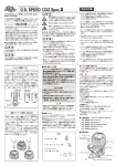
SYSTEM CONFIGURATION
INTERFACE UNIT IF-8000
MONITOR UNIT MU-100C
Note 2
Navigator
Control Unit
Note 1
Display
Unit
VGA Ext.
Monitor
Remote
Controller
Note 2
CONTROL UNIT CH-302
TRANSCEIVER UNIT
CH-303
Satellite compass
or
NMEA Input
12-24 VDC
DATA/VIDEO OUT
Rectifier
RU-1746B-2
Speaker
Motion Sensor
100/110/200/220 VAC
12-24 VDC
12/24 VDC
HULL UNIT
CH-304/305
Note 1: MU-100C is the standard supply
monitor unit. An external monitor
may be connected via the
interface unit (option). The drawing
above shows the system configuration
with the MU-100C.
Note 2: For blackbox type, MU-100C is
not supplied. Connect external
monitor (user supply) and control
unit to the interface unit.
iv
EQUIPMENT LISTS
Standard Supply
Name
Control Unit/
Monitor Unit
Control Unit
Interface Unit
Transceiver Unit
Hull Unit
Spare Parts
Installation
Materials
Accessories
Type
CH-302/
MU-100C
CH-302
IF-8000
CH-303
CH-304
CH-305
SP06-01101
SP06-01102
SP06-01103
SP06-01111
CP06-01200
CP06-01201
CP06-01202
CP06-01203
CP06-01204
CP06-01205
CP06-01261
CP06-01501
CP02-06600
CP02-06610
CP02-06620
FP02-05100
FP06-01410
Code no.
Qty
-
1
Not supplied with blackbox type
006-556-200
006-556-210
006-558-990
006-556-220
000-068-496
000-068-497
000-068-498
000-068-499
000-068-500
000-068-502
006-562-580
006-561-620
000-012-486
000-012-480
000-012-481
000-012-474
000-068-630
1
1
1
Not supplied with unibody type
For blackbox type (not required for MU-151C)
1
1
1
1
1
1 set
1
1 set
1 set
1 set
Remarks
400 stroke
See the following table for
Hull Unit Standard Supply.
250 stroke
For unibody type*
For transceiver unit*
For hull unit*
For interface unit*
06S4078 (5 m), 06S4080 (15 m), CP06-01251*
06S4078 (5 m), 06S4080 (30 m), CP06-01251*
06S4078 (5 m), 06S4080 (50 m), CP06-01251*
06S4078 (10 m), 06S4080 (15 m), CP06-01251*
06S4078 (10 m), 06S4080 (30 m), CP06-01251*
06S4078 (10 m), 06S4080 (50 m), CP06-01251*
For transceiver unit*
For hull unit*
MJ-A10SPF0002-0015 (0.15 m), for unibody type
MJ-A10SPF0002-015 (1.5 m ), for blackbox type
MJ-A10SPF0002-050 (5 m), for blackbox type
For unibody type, FP02-05101*, hood
For control unit, FP06-01120*, hard cover
*: See the lists at the back of this manual.
Hull Unit Standard Supply
Name
Raise/lower
Drive Unit
Soundome
Type
CH-3041
CH-3051
CH-3042
Flange
CH-2543
Assembly Kit for
CH-2544
field
SHJ-0006
Shaft
06-007-1572
Sonar Oil
4 lit.
Code no.
-
1 set
006-557-810
1 set
006-557-820
661-000-062
600-715-721
000-824-033
v
Qty
Remarks
1 set
1 set
1
1
See the lists at the back of
this manual.
See the lists at the back of
this manual.
2.2 m, for 3.5/5.2 m cable
3.8 m, for 5.2m cable
Options
Name
Remote Controller
Interface Unit
Motion Sensor
Monitor Unit
Control Unit
Clinometer
Loudspeaker
Signal Cable
Rectifier
Cable assy.
Control Unit
Separate Kit
Flush mount kit
Control unit flush
mount kit
Tank
Type
CH-256-E
IF-8000
MS-100
MU-100C
CH-302-E
BS-704
SC-05WR
S06-9-5
RU-1746B-2
MJ-A6SPF0012-050
MJ-A6SPF0012-100
MJ-A6SPF0011-050
MJ-A6SPF0011-100
OP06-15-1.5 NEW
OP06-15-5 NEW
OP02-83-1.5
OP02-83-5
OP06-16
OP06-17
OP06-18
06-007-1570-2
SHJ-0001-2
06-007-1571-2
06-021-4024-0
06-007-1573-0
OP10-5
Code no.
000-068-492
000-136-156
006-556-270
000-030-439
000-134-424
000-133-817
000-132-244
000-132-336
006-559-140
006-559-150
001-413-600
001-413-610
006-556-300
006-556-310
006-556-320
600-715-702
661-000-012
600-715-712
100-295-470
600-715-730
000-069-763
vi
Qty
1 set
1 set
1 set
1 set
1 set
1 set
1
1
1
1
1
1
1
1
1
Remarks
Extension cable for loudspeaker
6pin-6pin, 5m
6pin-6pin, 10m
6pin-4pin, 5m
6pin-4pin, 10m
For desktop, with 1.5 m
For desktop, with 5 m
For flush mount, with 1.5 m cable
For flush mount, with 5m cable
For unibody type
For separated display unit
1
1
1
1
1
1
1
Steel, 1m
Steel, 1.8m
Steel, 3.5m
FRP, 1m
FRP, 1.8m
Aluminum, 1m
1. MOUNTING
NOTICE
Do not apply paint, anti-corrosive sealant
or contact spray to coating or plastic
parts of the equipment.
Those items contain organic solvents that
can damage coating and plastic parts,
especially plastic connectors.
1.1
Monitor Unit/Control Unit
This searchlight sonar has two types of shipments, unibody type which is
shipped with monitor unit, and blackbox type which is shipped without a monitor
unit, but has an interface unit. For blackbox type, see page 1-5.
The control unit can be installed together with the monitor unit, or independently
of the monitor unit. For separate installation, the optional monitor kit is required.
These units can be installed on a tabletop or flush mounted in a console or
panel.
1.1.1
General mounting considerations
• Keep the monitor unit out of direct sunlight.
• Select a location where the unit(s) can easily be operated while observing the
fishing ground or area surrounding the vessel.
• For maintenance and checking purposes, leave sufficient space at the sides
and rear of the unit and leave slack in cable. (Refer to the outline drawing at
the back of this manual.)
1.1.2
Mounting Unibody type
1. Fasten the mounting base to the mounting location with four self-tapping
screws (5X20).
FRONT
Mounting base
2. Fasten the bracket at the rear of monitor/control unit with four binding screws
(M4x10).
1-1
1. MOUNTING
1
Bracket (rear view)
1
2
2
3
3
4
4
Bracket, rear view
3. Coat threads of upset screws (M6x16, 2 pcs.) used to fasten bracket to
mounting base.
4. Fasten the bracket to the mounting base with two upset screws. (Use the
upper holes to tilt the monitor unit 20°; lower holes to tilt it 9°.)
For 9 tilt
Mounting base
For 20 tilt
Bracket
Upset Screw
Fastening bracket to mounting base
1-2
1. MOUNTING
Flush mounting
Flush mounting for unibody (Type: OP06-16, Code no.: 006-556-300)
Name
Type
Code No.
Qty Remarks
Fixing metal
06-021-1311-2 100-279-612-10
1
Self-tapping screw 5x20
000-162-609-10
6
Hex. bolt
M4x12
000-162-939-10
4
1. Cut out a hole (W287 x H297) in the mounting location.
2. Fasten monitor/control unit with the fixing metal (supplied) and four hex. bolts
(M4x12, supplied).
3. Fasten the fixing metal assembled at step 2 to hole made at step 1 with six
self-tapping screws (5x20, supplied).
Hex. bolts
Fixing metal
1.1.3
Mounting separated monitor unit
1. Fasten the mounting base to the mounting location with four self-tapping
screws (5x20).
FRONT
Mounting base
2. Dismount the coupling plate to separate monitor unit from control unit.
3. Attach the bracket at rear of the monitor unit with four binding screws
(M4x10).
1-3
1. MOUNTING
Bracket (rear view)
1
1
3
2
2
4
3
4
Bracket, rear view
4. Coat threads of upset screws (M6x16, 2 pcs.) used to fasten bracket to
mounting base.
5. Fasten the bracket to the mounting base with two upset screws. (Use the
upper holes to tilt the monitor unit 20°; lower holes to tilt it 9°.)
Flush mounting for monitor unit (Type: OP06-17, Code no. 006-556-310)
Name
Type
Code No.
Qty
Remarks
Fixing metal
06-021-1321-2 100-279-622-10
1
Self-tapping screw 5x20
000-162-609-10
4
Hex. bolt
M4x12
000-162-939-10
4
1. Cut out a hole (W287 x H207) in the mounting location.
2. Fasten the fixing metal (supplied) to the monitor unit with four hex. bolts
(M4x12, supplied).
3. Fasten the fixing metal assembled at step 2 to hole made at step 1 with four
self-tapping screws (5x20, supplied).
Hex. bolts
Fixing metal
1-4
1. MOUNTING
1.1.4
Blackbox type
The blackbox type requires a VGA monitor, connected via the interface unit
IF-8000. Supply commercial monitor and interconnection cable (Max. length 15
m with Dsub-15P connectors of male, three rows of 15 pins). The monitor used
should satisfy the specifications shown below.
• VGA type
• ANALOG RGB 0.7 Vpp, positive polarity
• TTL level H, V, Negative polarity
Note: The LCD monitor MU-151C does not require the interface unit IF-8000.
For details, see the operator’s manual for MU-151C.
1.2
Control Unit
For blackbox type, fix the control unit to the mounting plate (supplied as
accessories).
See the parts list of FP06-01120 and outline drawings at the back of this manual.
1. Fix the mounting plate to the place selected with two self-tapping screws
(5X20, supplied).
2. Fix the bracket to the control unit with two hex. screws (M4X12, supplied).
3. Insert the screwdriver from the top of the mounting plate holes and then
tighten two hex. screws (M4X12) loosely.
4. Attach the control unit to the mounting plate, and fasten two hex. screws
tightly.
5. Attach two cosmetic caps to the holes at the top of the mounting plate.
Mounting plate
Cable entrance hole
Cable
Tapping screws (5X20)
Bracket
Fasten the screws to fix
the bracket.
Insert to the hex.
screws tightened
at step 3.
Bracket
Cable can be passed this direction.
6. Attach hard cover to protect the control unit.
How to remove the hard cover
Place your thumbs at the locations shown with
circles in the illustration at right, and then lift the
cover while pressing it with your thumbs.
1-5
1. MOUNTING
To mount the control unit separate from the monitor unit, the optional control unit
separate kit is required. Mount the control unit same as the above procedure.
See the outline drawing at the back of this manual to mount.
Type: OP06-15-1.5 NEW
Type: OP06-15-5 NEW
Name
Cable
Code no.: 006-559-140: with 1.5 m cable
Code no.: 006-559-150: with 5 m cable
Type
Code no.
Qty
MJ-A10SPF0002-015
000-142-878
MJ-A10SPF0002-050
000-131-411
Bracket
06-021-2112
100-281-880-10
1
Mounting Plate
06-021-2111-1
100-279-741-10
1
Self-tapping Screw
5x20
000-162-608-10
2
Cosmetic Cap
DP-687
000-165-997-10
2
Hex. bolt
M4x12
000-162-939-10
4
1
Remarks
For 1.5 m cable
For 5 m cable
Flush mounting for control unit
Type: OP02-83-1.5, Code no.: 001-413-600 (1.5 m cable)
Type: OP03-83-5, Code no.: 001-413-610 (5m cable)
Name
Type
Code No.
Qty
Remarks
Fixing metal
06-021-2101-2
100-279-732-10
1
Self-tapping screw
5x20
000-162-609-10
4
Hex. bolt
M4x12
000-162-939-10
2
MJ-A10SPF0002-015
000-142-878
1
1.5 m
MJ-A10SPF0002-050
000-131-411
1
5m
Cable assembly
Select
one.
1. Cut out a hole (W287 x H87) in the mounting location.
2. Fasten the fixing metal to the control unit with two hex. bolts (M4x12,
supplied).
3. Fasten the fixing metal assembled at step 2 to holes made at step 1 with four
self-tapping screws (5x20, supplied).
Hex. bolts
Fixing metal
1-6
1. MOUNTING
1.3
Transceiver Unit
1.3.1
General mounting considerations
• The mounting location should be well ventilated and dry.
• The unit can be mounted on a bulkhead or the deck.
• The maximum cable length between the transceiver unit and the raise/lower
drive unit is 50 m.
• The maximum cable length between the transceiver unit and the monitor
(interface) unit is 10 m.
• Keep the transceiver unit out of splash.
Mounting method
Fasten the transceiver unit with four self-tapping screws (5X20, local supplied).
For bulkhead mounting, do as follows:
1. Tighten upper self-tapping screws so there is 5 mm clearance between
bottom of screw head and bulkhead.
2. Hook the transceiver unit on the upper screws.
3. Tighten the upper screws followed by the lower screws.
475
428
4- 6
FIXING HOLES
16.5
296.5+1
LED
455+1
82
340
1.3.2
Transceiver unit
1-7
1. MOUNTING
1.4
Hull Unit
1.4.1
General mounting considerations
• Noise and air bubbles will affect performance.
• Do not turn on the equipment with the transducer exposed to air. Exposing the
transducer to air may damage it.
1.4.2
Installation position considerations
Discussion and agreement are required with the dockyard and ship owner in
deciding the location for the hull unit. When deciding the location, take into
account the following points:
• Select an area where propeller noise, cruising noise, bubbles and interference
from turbulence are minimal. Generally, the point at 1/3 to 1/2 of the ship’s
length from the bow or near the keel is the best. On-the-keel installation is
advantageous for minimizing oil consumption in comparison with off-the-keel.
If the hull unit cannot be installed on the keel, the center of the retraction tank
should be within 1 meter of the keel to prevent a rolling effect.
1/2
1/3
Within 1 meter
Installation location for hull unit
• Select a place where interference from the transducers of other sounding
equipment is minimal. The hull unit should be at least 2.5 meters away from
the transducers of other sounding equipment.
• An obstacle in the fore direction not only causes a shadow zone but also
aerated water, resulting in poor sonar performance. Be sure to locate the
transducer well away from any obstacle in the fore direction.
Mounting method
A typical mounting method is shown in the outline drawing at the back of this
manual. Consult ship’s owner, dockyard and user to determine appropriate
mounting method. Pay attention to safety (strength, watertightness) first,
followed by ease of maintenance and inspection.
1-8
1. MOUNTING
1.4.3
Transducer tank
Tank length
Shorten the transducer tank so the transducer is lowered into water as deep as
possible. Pay particular attention to the tank length Lt. Determine the length of
the main shaft.
• Length of main shaft = Lt + 200 mm (for 400
stroke)
• Length of main shaft = Lt + 50 mm (for 250
stroke)
Note: When the retraction tank is constructed
locally, finish it so that welding beads do
not protrude on the inner surface of the
tank. The tank guide will hit the bead,
burning out the raise/lower motor. Also, do
not position the welding bead in the ship’s
fore-aft line.
Welding bead
Welding bead
For small FRP ship
The retraction tank should be mounted in
parallel with the ship’s draft. For a small ship, however, the hull has 2 degrees of
tilt rising toward the bow. This creates high water pressure in the tank because
of the resistance at the rear of the tank well. To solve this problem, attach a fin to
the hull at the location shown in the figure below.
Retraction tank
Bottom of ship
Fin
This fin creates a smooth stream in the retraction dome. Fin specifications:
Height, 1-1.5 cm, Material, FRP.
1-9
1. MOUNTING
Mounting of transducer tank
Install the transducer tank referring to the hull unit outline drawings at the back of
this manual.
Note 1: When making a retraction tank locally, the inside diameter of the
retraction tank should be φ190±0.5 as shown in the outline at the back of this
manual. If larger, the hull unit may be damaged.
Note 2: Locate the retraction tank so that the center of any two bolt holes is
facing the ship’s bow.
a=b
a
b
1.4.4
Bow
Assembling and mounting of hull unit
The hull unit is shipped as the parts shown in the hull unit kit in the Equipment
Lists (page v). Assemble the hull unit as shown in the procedure below.
Note: Confirm the frequency of soundome before mounting by referring to the
table below.
Frequency
Specification
60/153 kHz
There is NO label attached on the dome.
85/215 kHz
There is the label “85/215 kHz” attached
on the dome.
For 85/215 kHz, the label is
attached here.
Necessary tools
Name
Specification
Remarks
Wrench
For M10 (Hex. size 17 mm)
Recommended: double offset wrench
Wrench
For M20 (Hex. size 30 mm)
Pipe Wrench
55 mm
For fixing gland
Ball Wrench
Hex size 4 mm
For fixing the dome
1-10
1. MOUNTING
1. Calculate necessary length of main shaft from the length of retraction tank Lt
and cut off the unnecessary portion.
Supplied length: 2.2 m or 3.8 m
Lt + 200 mm for 400 mm travel
Lt + 50 mm for 250 mm travel
Chamfer the edge to
protect O-ring from
damage.
Take care
not to damage.
2. Remove hex bolt, nut, spring washers, flat washers and trunnion pins from
the main body flange. Then, mount the raise/lower drive unit on the shaft
sleeve by using the hardware removed.
ING
RN
WA
WA
RN
ING
Raise/lower
drive unit
Flat
Nut
washer
Hex. bolt
(M10X30)
Flange assembly
Spring washer
Flat washer
Trunnion pin
Shaft sleeve and raise/lower drive unit assembly
3. Pass the transducer cable through the main shaft.
1-11
1. MOUNTING
4. Fully screw main shaft into the soundome neck, and then unscrew by four
turns. Coat threads with CEMEDINE HIGH SUPER.
Main Shaft
Grasp the soundome neck with a wrench,
and tighten the shaft with a pipe wrench.
Coat threads with CEMEDYNE
HIGH SUPER.
Applying CEMEDINE HIGH SUPER to main shaft
5. Screw in main shaft completely.
6. As shown in the drawing below, confirm that the narrowest gap between the
tank guide, and retraction tank in the range (20 to 170 mm) is within 0.5 mm.
Adjustment range
(travel) 250 or 400
Retraction tank
20 mm (400 travel) 170 mm (250 travel)
Tank guide
less than 0.5mm
Tank and tank guide, sectional view
1-12
1. MOUNTING
7. If the gap at a side is more than 0.5 mm, install shim(s) to make the gap
within 0.5 mm.
a) Unscrew four M10x50 bolts.
b) Unscrew four countersunk screws, then attach shim(s) with the countersunk
screws as shown below.
Nut
Flat washer
Countersunk screw
(M4x16)
Hex. bolt
(M10x70)
Guide plate
Shim (1.0)
Flat washer
Shim (1.5)
Spring washer
Hex. bolt
(M10X50)
Installing shims
1-13
1. MOUNTING
1800
8
1600
7
1400
6
1200
5
1000
4
800
3
600
400
2
200
1
0
0
189
190
191
192
193
Tank inside dia. Φ B (mm)
Shim thickness (mm)
Length A (mm) tank shortened
The table below shows tank length and necessary shim thickness. In addition,
the shim thickness shown is for one side. For example, when cutting the 1800
mm tank to 800 mm, the tank inside diameter is 191.25 mm, and shim thickness
is 2.5 mm as shown the table in below.
194
For 1 m tank
For 1.8 m tank
Shim thickness
The table below shows number of shims required and shim thickness.
Shim thickness
0
t2.0
t1.0
t0.5
Inside dia of tank 188.1
1-14
0.5
1
188.7
1
1.5
1
1
1
189.9
189.3
2
1
2.5
1
190.5
1
191.1
3
1
1
191.7
3.5
1
1
1
192.3
4
2
4.5
2
192.9
1
193.5
5
2
1
194.1
5.5
2
1
1
194.7
6
2
2
195.3
6.5
2
2
1
195.9
1. MOUNTING
8. Coat the inside of the tank guide with ADHESIVE 1104 200G. Then, fasten
tank guide at the neck of the main shaft securely with M10X80 bolts.
Hex. bolt
(M10X80)
: Coat with ADHESIVE 1104 200G
Flat washer
Spring washer
Nut
*
Bow mark
Bow
Face the tank guide
toward ship's bow.
Tank guide attachment
9. Pass the main shaft through the flange assembly.
10. Pass the main shaft through the shaft retainer at the raise/lower drive unit.
Pipe cap
U-nut
Shaft retainer
Spring washer
Hex. bolt M10X35
Main body flange
Bow mark
Bow
1-15
1. MOUNTING
11. Align the bow mark on the soundome with the bow mark on the flange
assembly, and then fix the main shaft with and shaft retainer.
12. Fix the jubilee clip to the main shaft.
Hex. bolt
Shaft retainer
15 mm
1-2 mm
Jubilee Clip
Main shaft
Note: Attach the shaft retainer so it is 15 mm from the top of the shaft. The
soundome is then placed 10 mm above the bottom of tank when retracted.
13. Insert grease cotton (supplied with flange assembly), and fix them with the
cotton retainer as follows.
a) Wind grease cotton onto main shaft.
b) Mark on the cotton as below.
c) Remove the cotton from the shaft, and then cut it at the position of the mark.
Discard the ends.
d) Wind cottons as shown below.
e) Push cottons into the flange assembly.
14. Tighten the grease cotton retainer.
Wind grease cotton
onto main shaft and
cut it as shown below.
Space joints of grease cotton
120 apart and push them into
body flange.
Spring washer
Cotton retainer
Installing grease cotton on the main shaft
15. Fasten the pipe cap (supplied) to main shaft.
16. Unscrew 10 pcs of M5X35 socket head cap screws with soundome fixing tool
to dismount soundome.
17. Remove and discard the protection sponge placed in soundome.
1-16
1. MOUNTING
Rotate 4 or 5
turns by hand
to make sure
that turning
mechanisms
are functioning
properly.
Socket head cap screw
10pcs, M5x30
Spring washer
O-ring
Remove.
Apply KINORUSTER.
Soundome
Protection sponge
Detaching the soundome
18. Stand the soundome upright on top of the soundome packing. Fill the
soundome with oil (supplied) so the level is 5 cm from the top of the
soundome. Keep the soundome packing for future use.
Ball wrench
Sonar oil
5 cm
Stand the soundome upright
on top of the soundome packing.
Filling the soundome with sonar oil
1-17
1. MOUNTING
CAUTION
Keep oil away from eyes. Where protective
goggles when working with the oil. The oil
cause inflammation of the eyes.
Do not touch the oil. The oil can cause
inflammation of the skin. Wear protective
gloves when working with the oil.
Do not ingest the oil. Diarrhea or vomiting
can result.
Keep the oil out of reach of children.
EMERGENCY
If the oil enters the eyes, flush with clean
water about 15 minutes. Consult a
physician. If oil contacts skin, wash with
soap and water. If the oil is ingested, see a
physician immediately.
DISPOSAL OF OIL AND ITS CONTAINER
Dispose of oil and its container in
accordance with local regulations.
For further information, contact place of
purchase.
STORAGE
Seal container to keep out foreign material.
Store in dark place.
19. Rotate the transducer manually to position it at the angle shown below, and
then refit the soundome.
Transducer
Soundome
.
Note 1: Do not lay the oil-filled soundome down for five minutes. Oil may leak.
1-18
1. MOUNTING
Note 2: When the soundome is painted (to keep marine life off the transducer),
observe the following precautions:
• Use only anti-fouling paint type MARINE STAR 20 (Manufacture: Chugoku
Marine Paint Co., Ltd., Japan).
• Paint only the plastic portion of the dome. Painting the metal parts causes
electric corrosion.
Paint area
20. Clean surface of gasket, tank flange and shaft sleeve, and then coat flange
gasket with ADHESIVE 1104 200G.
21. Lightly coat bolts, nuts and washers with KINORUSTER.
22. Set the hull unit into the retraction tank, taking care not to damage the
soundome.
U-nut
Shaft retainer
Spring washer
Hex. bolt M10X35
Nut
Spring washer
Flat washer
Flange assembly
Bow mark
Flange gasket
Retraction tank
flange
Flat washer
Hex. bolt M20X80
1-19
1. MOUNTING
23. Fix the shaft sleeve and retraction tank with hex bolts, flat washers and
spring washers.
Hex bolt
Shaft retainer
15 mm
1-2 mm
Jubilee clip
Main shaft
Bow
10 mm
1-20
1. MOUNTING
Checking manual raise/lower of soundome with hand crank
Perform this check after all wiring has been completed.
CAUTION
Turn the main power off before this check,
otherwise the raise/lower motor action may
cause injury.
1.
2.
3.
4.
Turn off the breaker on the hull unit.
Detach the gear cover.
Set wrench (opposite side19 mm) to the screw shaft gear.
The transducer should rise/lower smoothly with even force in upper to lower
limits. If not, the centers of the shaft sleeve and the retraction tank are not
aligned. Adjust the hull mounting position if necessary. Check the following
points.
• Painting inside tank not smooth.
• Inner diameter of tank not uniform.
• Welding bead is obstructing raising and lowering.
1-21
1. MOUNTING
1.5
Interface Unit
The interface unit is shipped with the blackbox type to enable connection of a
monitor. Note that this unit is not necessary when using monitor MU-151C.
1.5.1
General mounting considerations
• The mounting location should be well ventilated and dry. Avoid locations
subject to water splash or rain.
• The unit can be mounted on a bulkhead or the deck.
• The maximum cable length between the interface unit and the transceiver unit
is 10 m. Keep the length in mind when choosing a mounting location.
External
monitor
Transceiver 06S4078
unit
A
Interface
unit
06S4078
B
External
monitor
Transceiver 06S4078 Interface
unit
unit
A
1.5.2
Monitor unit
MU-100C
A+B<=15m
External
monitor
06S4078
Interface
unit
A+C<=15m
C
Mounting method
Fasten the interface unit with four self-tapping screws (5X20, local supplied).
For bulkhead mounting, do as follows:
1. Tighten upper self-tapping screws so there is 5 mm clearance between
bottom of screw head and bulkhead.
2. Hook the transceiver unit on the upper screws.
3. Tighten the upper screws followed by the lower screws.
315+0.5
1-22
4- 6
FIXING HOLES
137
120
79+0.5 23
335
295
1. MOUNTING
1.6
Motion Sensor MS-100 (option)
The MS-100 measures ship’s pitching and rolling angles with a sensor, using the
principles of the gyroscope. The MS-100 is free from error caused by ship’s
vertical and horizontal motion. Therefore, it can be installed at any convenient
location. However, ship’s semi-permanent inclination due to loading imbalance
cannot be detected. Compensate for this as described in Chapter 3.
1.6.1
Mounting considerations
• Vibration in the mounting area should be minimal.
• Locate the unit away from areas subject to water splash.
• The ambient temperature should not exceed 50°C.
1.6.2
Mounting procedure
Orient the FORE mark on the unit toward the ship’s bow and mount the unit level
to within 5° in all directions. For the offset, see Chapter 3.
FORE
θ ≤ 5°
AFT
1-23
1. MOUNTING
1.7
Clinometer BS-704 (option)
The clinometer detects ship’s inclination caused by ship’s rolling, pitching and its
output is used to stabilize the sonar beam against rolling and pitching.
The clinometer is, in principle, a pendulum. It measures the inclination of the
ship by sensing the direction of gravity acted on it and therefore when installed
on a ship, it should be placed on or near the rotation axes of the ship’s rolling
and pitching. If it is placed away upward from the axes, the measured value
becomes larger than the actual value. On the other hand, if it is placed below the
axes, the measured value is smaller than actual value. The same can be said
when it is placed far to the left or right from the axes.
The rotation axes of pitching and rolling are theoretically considered to be
located on the level of the ship’s draft and in the center of the ship. In other
words, as follows:
1. Vertical position of the pitching and rolling axes is on the draft level of the
ship.
2. Horizontal position of the rolling axis is in the center of the ship’s
port-starboard line.
3. Horizontal position of the pitching axis is in the center of the ship’s fore-aft
line.
From 1, 2 and 3 above, the crossing point of the two axes is indicated by the
black dots in the illustration below. The clinometer should be mounted as close
as possible to this point.
Rolling Axis
Pitching Axis
Water line
Note 1: The area near the hull unit is too low to install the Clinometer and should
be avoided, since the polarity of the measured value is reversed.
Note 2: When it is impossible to install the clinometer on the intersecting point of
both rolling and pitching rotational axes, a special effort should be made to
install it at a place where the vertical distance to the intersecting point is
shortest.
Note 3: Install the clinometer with the bow mark pointing toward ship’s bow.
Note 4: Be sure to adjust the clinometer following the procedure in section 3.6.
1-24
2.
WIRING
2.1
Wiring Among Units
• The figure on the next page shows wiring among units.
• The signal cables are fitted with connectors. Connect the cables to the monitor,
transceiver and hull units referring to the interconnection diagram on page
S-1.
• The power cable should be arranged locally. Use power cable type
DPYCYS-2.5 (Japan Industrial Standard cable) or equivalent cables. Attach
crimp on lugs (FV2-4) as shown below.
Armor
30
40
5
FV2-4 (blue)
Vinyl sheath
Wind
vinyl tape.
Braided shield
(Fold the braided shield back on the vinyl sheath.
Fix here with the cable clamp.)
Conductor
Insulator
Inclusion
Tape
S = 2.5 mm 2
=15.2 mm
Braided shield
Sheath
Armor
Vinyl sheath
• The raise/lower drive motor and breaker are different depending on ship’s
mains.
• Install the mains switch for the sonar where it can be easily accessed. Turn off
this switch when the sonar is not being used, to reduce power consumption
and to prevent the transducer from slipping by vibration.
• If the D-sub connector is too large to pass through the hole in a bulkhead, etc.
remove it, pass the cable through the hole and then reattach the connector.
2-1
2. WIRING
Navigation equipment
Monitor/control unt
CH-302/MU-100C
Note 3
MJ-A10SPF0002-0015
0.15 m
Note 1
(5 m)
06S4078
(5/10m)
Note 2
Interface unit
*a
IF-8000
*b
Remote
controller
Monitor
(User supply)
Transceiver unit
CH-303
Note 4
MJ-A6SPF
0012
Loudspeaker
(w/cable)
DPYCYS-2.5
12-24 VDC
Satellite
compass
06S4037
(10m)
Ext. KP
Motion sensor
Clinometer
06S4081
(3.5/5.2m)
06S4080 (15/30/50m)
Hull unit
CH-304
CH-305
Note 1: Optional cable between the
monitor unit and control unit
for separate installation
-MJ-A10SPF0002-015 (1.5m)
-MJ-A10SPF0002-050 (5m)
Note 2 a b<15m
Note 3: MU-151C can be connected for MU-100C.
In this case, the monitor and control units should
be mounted seprately.
Also, the MU-151C requires the independent power.
Note 4: Satellite compass SC-50/110 can be connected.
See the schematic diagram.
Wiring, with monitor
2-2
12/24 VDC
250V-DPYCYS-2.5
Interface unit
IF-8000
Note 1
Navigation equipment
Max. 15m
External monitor Note 2
Note 3
*a
06S4078
(5/10m)
06S4078
(5/10m)
Note 3 * b
Interface unit
External monitor
CONT
MJ-A10SPF0002-050
(5m)
Control unit
CH-302
REM
Control unit, rear view
(5m)
Remote controller
Transceiver unit
CH-303
SPEAKER
MJ-A6SPF
0012
Loudspeaker
(w/cable)
DPYCYS-2.5
Satellite
compass
12-24VDC
06S4081
(3.5/5.2m)
Ext. KP
06S4037
(10m)
Monitor unit
Clinometer
06S4080(15/30/50m)
12/24VDC
DPYCYS-2.5
Hull unit
Note 1: Two interface units may be connected.
Note 2: For interface unit, the external monitor (user
supply) is required.
CH-304
CH-305
Note 3 *a b<15m
Wiring, without monitor
2-3
2. WIRING
2.2
Transceiver Unit
Connect the cables as shown in the figure below.
06P0254
J3
7P-NH connector
(local supply)
J6
J5
J2
06P0255
Tie these cables with
locking spacer.
*Note
SPEAKER
External loudspeaker
SC-05WR
HULL
UNIT
DATA/VIDEO OUT
Monitor unit MOTION SENSOR
MU-100C
or
06S4080
Interface unit
Hull unit
External KP
IF-8000
CH-304/CH-305
Motion sensor
MS-100
or
Clinometer
BS-704
+
*Note
Earth
To ship's
earth
NMEA/SATELLITE COMPASS
Satellite compass
SC-50/110, etc.
*: Fix the braided shield with the clamp.
Transceiver unit, internal view
2-4
-
06P0258
TB1
12-24VDC
DPYCYS-2.5
Ship's mains
12-24 DCV
Synchronizing Transmission with Echo Sounder or Other Sonar
To synchronize transmission of the CH-300 with an echo sounder or other type
of sonar, connect it as shown below.
H7P-SHF (local supply)
Transceiver unit
Vinyl wire (local supply)
06P0254
Sonar, E/S
AWG22-26
J3
3 to 15V
positive
KP OUT
+5V to 15V
GND
KPI 3
EXT_SW 5
GND 6
HULL UNIT clamp
Connection of transceiver unit to other sonar/echo sounder
Note: Outputting KP of CH-300 to other sonar, echo sounder
Transceiver unit
06P0254
J3
KPO
12V
positive
2
(E/S transmits, SONAR)
GND 6
Outputting KP of CH-300 to other sonar, echo sounder
2-5
2. WIRING
2.3
Hull Unit
Pass the cables to the 06P0257 Board, through the cable protectors.
Fasten glands securely
by hand.
J2
06P0257
J3
Cable from transducer
06S4081
Attach the EMI core RFC-4 (supplied)
to this cable, and then fix the core to the
cable for JI with the cable tie CV-100N
(supplied).
J1
*Note
J1
J2
Cable from transceiver unit
06S4080
*Note
TB2
+
Power cable
250V-DPYCYS-2.5
-
*Note
Power switch
Should always be in up position (ON).
06P0243
Earth
Connect to ship's earth.
*Note: Fix the braided shield with cable clamp.
Hull unit, inside view
Attaching EMI core RFC-4
2-6
2.4
Interface Unit
DATA/VIDEO IN DATA/VIDEO OUT RGB OUT
Transceiver unit cable
06S4078
Monitor unit
cable
06S4078
CONT
NMEA
VGA
NAV
Earth
monitor Control
Connect to ship's earth.
unit
cable
MJ-A10SPF0002
(1.5/5 m)
The blackbox type requires connection of a VGA monitor, via the interface unit
IF-8000. Supply monitor and interconnection cable (Max. length 15 m with
Dsub-15P connectors of male, three rows of 15 pins). The monitor used should
satisfy the specifications shown below.
• VGA type
• ANALOG RGB 0.7 Vpp, positive polarity
• TTL level H, V, Negative polarity
Note 1: Two interface units can be connected to the transceiver unit in parallel.
Note 2: When using DATA/VIDEO OUT port, cut and remove the rubber covers
as below to attach connectors to the interface unit.
Remove the
fixing metals.
Cut and remove
the covers.
Note 3: Connect control unit or navigator equipment to either interface unit or
monitor unit (supplied by FURUNO).
Note 4: When connecting the monitor unit MU-100C to the interface unit, or two
interface units in parallel to the transceiver unit, the length of cables should be
as shown in the figure on next page. Note that two cables 06S4078 (10 m
length) cannot be used.
2-7
2. WIRING
External
monitor
Transceiver 06S4078 Interface
unit
A
unit
06S4078 Display unit
MU-100C A+B<15m
B
Control unit may be connected
to interface unit or display unit.
External
monitor
External
monitor
Transceiver 06S4078
unit
A
Interface
unit
06S4078
C
Interface
unit
A+C<15m
Connect control unit to an
interface unit.
2.5
I/O Sentences
Talkers may be chosen from among GP, LC, LA, DR, DE and other (II). Refer to
“NAV DATA” in System Setting 1 menu.
Available I/O sentences
Sentences
2-8
I/O
Remarks
GLL
I
Geographic position, latitude/longitude
GGA
I
Global positioning system fix data
RMA
I
Recommended minimum specific LORAN-C data
RMC
I
Recommended minimum specific GPS/TRANSIT data
VTG
I
Course over ground and ground speed
VHW
I
Water speed and heading, any talker
HDG
I
Heading, magnetic, any talker
HDM
I
Heading, magnetic
HDT
I
Heading, true, any talker
VDR
I
Set and drift, any talker
DBS
I
Depth below surface, any talker
DBT
I
Depth below transducer, any talker, NMEA Version 1.5
DPT
I
Depth, any talker, NMEA Version 2.0
MTW
I
Water temperature, any talker
MDA
I
Water temperature, any talker
att
I
True heading, pitching, rolling, P sentence
TLL
O
Target latitude and longitude
3. ADJUSTMENTS
3.1
General Checks
General checks
Check Item
Check point, Rating
On-keel Installation
Retraction tank level
Off-keel Installation
Within 1 m
Clearance between transducer and
bottom of retraction tank when
transducer is completely retracted
by hand crank
1 cm
Transducer travel
(lowered by hand clank)
400 travel:
Minimum 30 cm
Note: For checking purposes, a
clearance of approximately 1 meter
is required beneath the bottom of
the transducer.
Transducer heading
250 travel:
Minimum 22 cm
Bow mark on the shaft sleeve should face to
ship's bow.
Bow
3-1
3. ADJUSTMENT
General checks (con’t)
Check Item
Check point, Rating
Wiring check
All cables are correctly connected.
All lead wires are tightly fixed with contact pins
or crimp-on lugs.
All screws are firmly fastened.
Cables are firmly secured.
Cable shields are properly grounded.
Rejecting source of noise and
interference
Noise generating machinery (motor,
radiotelephone, TV set, etc.) are not placed
nearby.
Magnetic devices are not placed in the vicinity of
display unit.
3.2
Earth
Each unit is grounded with a copper strap.
Ship’s mains voltage
Ship’s mains voltage is stable 12 or 24 VDC.
Watertightness
Water should not leak from the main body flange
or along the main shaft.
Checking TX Frequency
Check the TX frequency after installing the equipment.
1. Press the MENU key to open the menu.
2. Press the cursor pad to select SYS at the top of the menu display.
3. Press ▼ to select GO TO SYS MENU.
MENU
COM1
COM2 HORZ VERT
GO TO SYS MENU
: SELECT
YES
: CHANGE
ES
SHORT-CUT
NO
MENU: END
User menu (SYS)
4. Press ◄ to select YES to display the system menu.
3-2
SYS
3. ADJUSTMENT
** SYSTEM MENU **
SYSTEM SETTING:
RANGE-SONAR MODE
RANGE-VERTICAL MODE
RANGE-E/S MODE
RANGE-TRACK MODE
COLOR PALETTE
LANGUAGE
SYSTEM BACKUP
LOAD BACKUP DATA
HEADING OFFSET, DRAFT OFFSET
ADJ MOTION SENSOR
TX FREQ ADJUST
TEST
TEST PATTERN
DEMO MODE
DEFAULT
: MENU DISPLAY MENU: END
: SELECT
System menu
5. Press ▼ to select TEST.
6. Press ► to show the test display.
MAIN PROGRAM NO. 0650111-**.**
PANEL PROGRAM NO. 0650112-**.**
ROM
: OK
RAM
: OK
VRAM
: OK
NMEA 1
NMEA 2
: OK
: OK
TX FREQUENCY
: 85/215 kHz (or 60/153 kHz)
ROLL
MS: 10
SC: _ _ _
PITCH
MS: 10
SC: _ _ _
PULSES
NG
359
0
TRAIN
TEST COUNT=
PANEL
0
0
REMOTE CONTROL
: 0
0
0
0
0
0
0
0
0
0
0
0
0
0
0
0
0
0
0
0
0
0
0 0 0
0
0
0 0 0
0
0
EXIT
0
0
0
0
0
0
0
** Program Version No.
Test display
7. Check the frequency at the TX FREQUENCY line on the test display.
8. Press the MENU key several times to close the menu.
3-3
3. ADJUSTMENT
3.3
Heading Alignment Setting
The heading line can be compensated from the system menu ( –180° to +180°).
1. Locate a target (buoy, etc.) in the bow direction and display it on the screen
at close range, read deviation. The heading alignment is correct when the
target is displayed at 12 o’clock on the screen.
Heading
12 o'clock position
Buoy
When on-screen target is skewed right,
transducer heading is skewed left.
Checking heading alignment
2.
3.
4.
5.
6.
Press the MENU key to display the menu.
Press ◄ ► to select SYS at the top of menu display.
Press ▼ to select GO TO SYS.
Press ◄ to select YES to display the system menu.
Press ▼ to select HEADING OFFSET, DRAFT OFFSET, and then press ►
to display the heading offset display.
** HEADING OFFSET/DRAFT OFFSET **
HEADING
:
0 ˚
(-180˚ - +180˚)
DRAFT
:
0.0 ˚
(0.0 - 60.0m)
: SELECT
: CHANGE
MENU: END
Heading offset display
7. Press ◄ or ► to align heading (1° step) so that the target selected at step 1
appears at the twelve o’clock position.
8. Press ▼ to choose DRAFT.
9. Press ◄ or ► to set ship’s draft.
10. Press the MENU key twice to close the menu.
11. Confirm that the target on heading direction appears at the twelve o’clock
position.
3-4
3. ADJUSTMENT
3.4
Setting for Synchronizing Transmission with
other Equipment
To synchronize transmission with other echo sounder (see paragraph 2.2), do as
follows:
1. Press the MENU key to display the menu.
2. Press ◄ to select COM1 at the top of menu display.
MENU
COM1
COM2 HORZ VERT
TX POWER
MAX
PULSELENGTH
TX RATE
LONG
10
OFF
INT REJECT
AGC
AUDIO LEVEL
: SELECT
ES
PRESET
SYS
OFF
0
: CHANGE
MENU: END
Menu (COM1)
3. Press ▼ to select TX RATE.
4. Press ► to display the setting window.
5
TX RATE
EXT. MIN
MAX
(EXT., 1-10)
TX RATE window
5. Press ◄ several times to select EXT.
6. Press the MENU key to close the menu.
3-5
3. ADJUSTMENT
3.5
Setting for Satellite Compass
FURUNO Satellite Compass SC-50/110 can be connected to feed
rolling/pitching data to this equipment. Connect the SC-50/110 sensor to the
NMEA/SATELLITE COMPASS port, and set up this port as below.
1.
2.
3.
4.
5.
Press the MENU key to show the menu.
Press ► to select SYS at the top of menu display.
Press ▼ to select GO TO SYS MENU.
Press ◄ to select YES to display the system menu.
Press ▼ to select SYSTEM SETTING.
** SYSTEM SETTING 1 **
MENU
POSITION
TRACK
1
2
: SHIP'S L/L
: OFF
ON
SHIP'S LOP
CURSOR L/L
CURRENT DATA
: OFF
HEADING INDICATION : TRUE
FLOW FROM
AZ
NORTH MARK
CSE DATA
NAV DATA
: OFF
: NAV
: GPS
ON
GYRO
LoranC LoranA DR DECCA OTHERS
NAV2 BAUDRATE
: 4800
9600
19200
38400
TVG CORRECTION
UNIT
: OFF
: m
1/2
ft
1/1
fa
HIRO P/B
TEMP
:
TARGET L/L
: OFF
CUSTOM KEY
ETA MARK
: PRESET KEY SHORT-CUT KEY
10sec 30sec 1min
: OFF
: SELECT
C
: CHANGE
FLOW TO
F
ON
3min
6min
MENU: END
System setting 1 menu
6. Press ▼ to select NAV 2 BAUDRATE, and then press ► to select 38400.
7. Press ▲ to select MENU at the top of the menu, and then press ► to select
2.
3-6
3. ADJUSTMENT
** SYSTEM SETTING 2 **
: 1
MENU
2
GAIN SETTING PROTECT : OFF
ON
HORZ/HISTORY
: OFF
ON
HORZ/VERT ZOOM
: OFF
ON
HORZ/PLOTTER
: OFF
ON
EMPHASIS MODE
: OFF
NORMAL
STABILIZER
AUTO RETRACTION
: OFF
: OFF
MOTION SENSOR
(OFF, 5-15 kt)
SPEED ALARM/MESSAGE : OFF
SWEEP INDICATOR
: DOT
ON
LINE
DEFAULT SETTING
YES
: NO
RED
SAT. COMPASS
MAXIMUM ALLOWABLE SPEED IS 15 KNOTS WHILE SOUNDOME IS BEING
RETRACTED. IF VESSEL HAS REPAID ACCELERATION CAPABILITIES,
AUTO RETRACTION SETTINGS OF 10-12 KNOTS ARE MANDATORY TO
AVOID CATASTROPHIC DAMAGE TO SOUNDOME ASSY. ANY PHISICAL
DAMAGE TO THE SOUDOME ASSY. IS CONSIDERED ABUSE AND
IS NOT A WARRANTY ISSUE.
: SELECT
: CHANGE
MENU: END
System setting 2 menu
8. Press ▼ to select STABILIZER.
9. Press ► to select SAT. COMPASS.
10. Press the MENU key twice to close the menu.
Note: To output data from SC-50/110 in NMEA format, set the SC-50/110 as
follows.
-Output format: IEC ed1
-Sentence: ATT (For others, set all OFF.)
-Baud rate: 38400 bps
-Cycle: 25 ms
(Talker : any)
Note: When connecting the analog signal of Satellite Compass SC-50/110 to the
MOTION SENSOR port on the transceiver unit, choose MOTION
SENSOR at step 9 in the above procedure. For wiring details, see the
interconnection diagram at the back of this manual.
3-7
3. ADJUSTMENT
3.6
Setting of Motion Sensor/Satellite Compass
When connecting the motion sensor, clinometer or satellite compass, enter
ship’s roll and pitch angles as shown below. Note that the adjustment can be
done only when connected to the MOTION SENSOR port. For the satellite
compass, however, do not duplicate this adjustment; enter values at one location
only.
1.
2.
3.
4.
5.
Press the MENU key to display the user menu.
Press to ► select SYS at the top of the menu display.
Press ▼ to select GO TO SYS.
Press ◄ to select YES.
Press ▼ to select ADJ MOTION SENSOR, and then press ► to display the
ADJ MOTION SENSOR menu.
** ADJ MOTION SENSOR **
ROLL ANGLE:
0˚
ADJ: +5* ˚
(-10˚ - +10˚)
PITCH ANGLE: 0˚
ADJ: +5* ˚
(-10˚ - +10˚)
: CHANGE
: SELECT
MENU: END
*: For Clinometer BS-704, tilt angle is displayed. For Motion Sensor MS-100,
the readout is "0" (zero) when the ship is stopped, regardress of actual roll or pitch.
Adj motion sensor menu
6. Press ▲ or ▼ to select ROLL ANGLE or PITCH ANGLE.
7. Press ◄ or ► to adjust (-10° to +10°).
8. For MS-100, use a clinometer or other similar measuring device to measure
ship’s semi-permanent inclination angle. Take the polarity of the angle. For
example, if the stern is 3° down, set -3°.
+
0
–
+
+
0
–
-
ROLL ANGLE
Starboard up
Starboard down
PITCH ANGLE
Stern up
Stern down
For clinometer BS-704, adjust so that the indication shows “0” (zero).
9. Press the MENU key several times to close the menu.
3-8
3. ADJUSTMENT
3.7
System Back Up
After setting up the equipment, follow the procedure below to back up system
settings. Backup data can be loaded in the event of equipment trouble, to restore
previous system settings.
1.
2.
3.
4.
Press the MENU key to display the user menu.
Press ► to select SYS at the top of the menu.
Press ▼ to select GO TO SYS MENU.
Press ◄ to select YES.
The system menu appears.
5. Press ▼ to select SYSTEM BACKUP.
6. Press ► to display the system backup menu.
** SYSTEM BACK UP**
ARE YOU SURE?
:
NO
YES
NOTE: OVERWITES PREVIOUS BACKUP DATA
: CHANGE
MENU: END
System backup menu
7. Press ► to select YES.
8. Press the MENU key to backup data.
The backup data is saved, and then return to the System menu.
9. Press the MENU key to return to the normal display.
3-9
3. ADJUSTMENT
3.8
Setting of Interface Unit
Set DIP switch S1 in the interface unit as follows.
• A unit is connected to DATA/VIDEO OUT port of the interface unit : all OFF.
• Nothing is connected to DATA/VIDEO OUT port of the interface unit: all ON.
OFF
J1
J2
J6* J7*
BUFFER
ON
THROUGH
S1
J3
*: J6 and J7 set to "THROUGH" side.
Interface unit, DIP switch S1 location
External
Monitor
Processor
Unit
Interface
Unit
Monitor
Unit
S1:All OFF
External
Monitor
Processor
Unit
Interface
Unit
S1:All ON
Processor
Unit
3-10
External
Monitor
External
Monitor
Interface
Unit
Interface
Unit
S1:All OFF
S1:All ON
⇟ภ
01
%#$.'#55;
㩃㨺㩖㩨㩣⚵ຠ
%#$.'#55;
㩃㨺㩖㩨㩣⚵ຠ
%#$.'#55;
㩃㨺㩖㩨㩣⚵ຠ
%#$.'#55;
㩃㨺㩖㩨㩣⚵ຠ
%#$.'#55;
㩃㨺㩖㩨㩣⚵ຠ
⇛ޓޓ࿑
176.+0'
ᢙ㊂
36;
#5:
ㆬᛯޓ61$'5'.'%6'&
ㆬᛯޓ61$'5'.'%6'&
ㆬᛯޓ61$'5'.'%6'&
ㆬᛯޓ61$'5'.'%6'&
ㆬᛯޓ61$'5'.'%6'&
↪ㅜ㧛⠨
4'/#4-5
㧲㨁㧾㨁㧺㧻ޓ㧱㧸㧱㧯㨀㧾㧵㧯ޓ㧯㧻ޓ㧚㧘㧸㨀㧰
%1&'01
5/
%1&'01
5/
%1&'01
5/
%1&'01
5/
%1&'01
5/
ဳฬ㧛ⷙᩰ
&'5%4+26+105
#5: 㧔⇛࿑ߩኸᴺߪޔෳ⠨୯ߢߔ&ޓޕ+/'05+105+0&4#9+0)(144'('4'0%'10.;㧕
ฬޓޓ⒓
0#/'
+056#..#6+10/#6'4+#.5
Ꮏ᧚ᢱ
%*5ޔ%*
%1&'01
6;2'
A-1
A-2
%2
6;2'
'/+%14'
'/+㩄㨻
%4+/210.7)
⌕┵ሶ
2.#56+%$#0&
㩄㩧㩗㩨㨹㩂㩇
⇛ޓޓ࿑
176.+0'
%1&'01 4(%
4(%
%1&'01
(8㨻㨿
%1&'01 %80
%80
ဳฬ㧛ⷙᩰ
&'5%4+26+105
㧲㨁㧾㨁㧺㧻ޓ㧱㧸㧱㧯㨀㧾㧵㧯ޓ㧯㧻ޓ㧚㧘㧸㨀㧰
㧔⇛࿑ߩኸᴺߪޔෳ⠨୯ߢߔ&ޓޕ+/'05+105+0&4#9+0)(144'('4'0%'10.;㧕
#8:
6916;2'5#0&%1&'5/#;$'.+56'&(14#0+6'/6*'.19'4241&7%6/#;$'5*+22'&+02.#%'1(6*'722'4241&7%6
37#.+6;+56*'5#/'
ဳᑼ㩄㨺㩎㩨⇟ภ߇㧞Ბߩ႐วޔਅᲑࠃࠅᲑߦઍࠊࠆㆊᷰᦼຠߢࠅޔ߅ߥޓޕߔ߹ߡߞ߇߆ࠄߜߤޔຠ⾰ߪᄌࠊࠅ߹ߖࠎޕ
ฬޓޓ⒓
0#/'
*':$1.6
㨻㩖㩩㩈㨹㩎7+㩈㩛㩇$
9#5*'4$+0&+0)
*'#&5%4'9
㧗㩔㩨㨼㩧㩎㩨㩈㩛㩇(
5'.(6#22+0)5%4'9
㩎㩡㩇㩊㨹㩕㩩㩧㩒㩆㩨ޓ㩆㨷
$4#%-'6
㩔㩧㩀㩨㨺
/1706+0)$#5'
㩎㩢㩌㩃㩊㩨㨼
ฬޓޓ⒓
0#/'
⇛ޓޓ࿑
176.+0'
ဳฬ㧛ⷙᩰ
&'5%4+26+105
(2
%1&'
01
/:575
%1&'
01
/:%9/$%4㩕㩡
%1&'
01
:575
%1&'
01
%1&'
01
ᢙ㊂
36;
6;2'
%1&'01
↪ㅜ㧛⠨
4'/#4-5
(,: A-4
㧲㨁㧾㨁㧺㧻ޓ㧱㧸㧱㧯㨀㧾㧵㧯ޓ㧯㧻ޓ㧚㧘㧸㨀㧰
㧔⇛࿑ߩኸᴺߪޔෳ⠨୯ߢߔ&ޓޕ+/'05+105+0&4#9+0)(144'('4'0%'10.;㧕
(,:
ဳᑼ㩄㨺㩎㩨⇟ภ߇㧞Ბߩ႐วޔਅᲑࠃࠅᲑߦઍࠊࠆㆊᷰᦼຠߢࠅޔ߅ߥޓޕߔ߹ߡߞ߇߆ࠄߜߤޔຠ⾰ߪᄌࠊࠅ߹ߖ
ࠎޕ
6916;2'5#0&%1&'5/#;$'.+56'&(14#0+6'/6*'.19'4241&7%6/#;$'5*+22'&+02.#%'1(6*'722'4
241&7%637#.+6;+56*'5#/'
⇟ภ
01
#%%'5514+'5
⇟ภ
01
+056#..#6+10/#6'4+#.5
ઃዻຠ
↪ㅜ㧛⠨
4'/#4-5
#8: Ꮏ᧚ᢱ
ᢙ㊂
36;
%1&'01
A-3
*':$1.6
5.166'&9#5*'4
*'#&
ⷺ㩇㩢㩦㩢㩈㩛㩇$
%15/'6+%2.7)
㩘㨺㩣㩖㩩㩡㩂㩨
5'.(6#22+0)5%4'9
㩎㩡㩇㩊㨹㩕㩩㩧㩒㩆㩨ޓ㩆㨷
%10641.70+6$4#%-'6
㩉㨽㩅㩖㩨㩡㩃㨹㩎
10641.70+6/1706+0)
$#5'
ᠲขઃบ
ฬޓޓ⒓
0#/'
⇛ޓޓ࿑
176.+0'
%1&'
01
/:575
%1&'
01
&2㩂㩥
%1&'
01
:575
%1&'
01
41*5
%1&'
01
ဳฬ㧛ⷙᩰ
&'5%4+26+105
ᢙ㊂
36;
(2
6;2'
↪ㅜ㧛⠨
4'/#4-5
#5: 㧲㨁㧾㨁㧺㧻ޓ㧱㧸㧱㧯㨀㧾㧵㧯ޓ㧯㧻ޓ㧚㧘㧸㨀㧰
㧔⇛࿑ߩኸᴺߪޔෳ⠨୯ߢߔ&ޓޕ+/'05+105+0&4#9+0)(144'('4'0%'10.;㧕
#5:
ဳᑼ㩄㨺㩎㩨⇟ภ߇㧞Ბߩ႐วޔਅᲑࠃࠅᲑߦઍࠊࠆㆊᷰᦼຠߢࠅޔ߅ߥޓޕߔ߹ߡߞ߇߆ࠄߜߤޔຠ⾰ߪᄌࠊࠅ߹ߖ
ࠎޕ
6916;2'5#0&%1&'5/#;$'.+56'&(14#0+6'/6*'.19'4241&7%6/#;$'5*+22'&+02.#%'1(6*'722'4
241&7%637#.+6;+56*'5#/'
⇟ภ
01
#%%'5514+'5
ઃዻຠ
%1&'01
A-5
A-6
A-7
㩖㩡㩧㩆㩨⚵ㇱຠ
⇟ภ
01
⇛ޓޓ࿑
176.+0'
ᢙ㊂
36;
#8:
᨞บタߖบߦⵝ⌕ޓޓ
24'#66#%*'&61
(.#0)'#55;
᨞บタߖบߦⵝ⌕ޓޓ
24'#66#%*'&61
(.#0)'#55;
᨞บタߖบߦⵝ⌕ޓޓ
24'#66#%*'&61
(.#0)'#55;
᨞บタߖบߦⵝ⌕ޓޓ
24'#66#%*'&61
(.#0)'#55;
᨞บタߖบߦⵝ⌕ޓޓ
24'#66#%*'&61
(.#0)'#55;
᨞บタߖบߦⵝ⌕ޓޓ
24'#66#%*'&61
(.#0)'#55;
↪ㅜ㧛⠨
4'/#4-5
#8: 㧲㨁㧾㨁㧺㧻ޓ㧱㧸㧱㧯㨀㧾㧵㧯ޓ㧯㧻ޓ㧚㧘㧸㨀㧰
%1&'01
5*0
%1&'01
5*,
%1&'01
(
%1&'01
%1&'01
%1&'01
㩀㩂/
%1&'01
ဳฬ㧛ⷙᩰ
&'5%4+26+105
%*
6;2'
㧔⇛࿑ߩኸᴺߪޔෳ⠨୯ߢߔ&ޓޕ+/'05+105+0&4#9+0)(144'('4'0%'10.;㧕
.#$'.(14)4'#5'%16610
㩂㩨㩢㩇㩄㨹㩎㩧㩔㩢㩙㨺㩂
)#5-'6
㩖㩡㩧㩆㩨㩔㩩㨹㩁㩧
(.#0)'$75*
㩖㩡㩧㩆㩨㩖㩨㨹㩆㨷
%166104'6#+0'4
㩂㩨㩢㩇㩄㨹㩎㩧߃บ
64700+102+0
㩎㩡㩐㨿㩧㩕㩩㩧
)4'#5'%16610
㩂㩨㩢㩇㩄㨹㩎㩧
(.#0)'#55'/$.;
᨞บタߖบ
ฬޓޓ⒓
0#/'
(.#0)'#55'/$.+0)
2#465
%1&'01
A-8
%*
6;2'
#22.;+0)#&*'5+8'
㩈㩜㩊㩨㨼㩧ႣᏓⷐ㗔ᦠ
5*+/
㩆㩛
5*+/
㩆㩛
5*+/
㩆㩛
$#..94'0%*
㩘㩨㨺㩣㩤㩧㩋
%'/'&+0'*+)*572'4
㩈㩜㩊㩨㨼㩧㩔㨼㩇㨺㩔㩩㨺
.+37+&)#5-'65
㨾㩁㩆㩨㨸㨽㩀㩨㩇㩃㨹㩎
#06+%14415+8'
5'#.#06
㩁㩓㩡㩇㩊
ฬޓޓ⒓
0#/'
⇛ޓޓ࿑
176.+0'
%1&'
01
,
%1&'
01
%1&'
01
%1&'
01
%1&'
01
69$
%1&'
01
)㩈㨹㩎
%1&'
01
6$)
%1&'
01
)㨼㩢
ဳฬ㧛ⷙᩰ
&'5%4+26+105
ᢙ㊂
36;
↪ㅜ㧛⠨
4'/#4-5
㧲㨁㧾㨁㧺㧻ޓ㧱㧸㧱㧯㨀㧾㧵㧯ޓ㧯㧻ޓ㧚㧘㧸㨀㧰
#8:
㧲㨁㧾㨁㧺㧻ޓ㧱㧸㧱㧯㨀㧾㧵㧯ޓ㧯㧻ޓ㧚㧘㧸㨀㧰
#8:
ဳᑼ㩄㨺㩎㩨⇟ภ߇㧞Ბߩ႐วޔਅᲑࠃࠅᲑߦઍࠊࠆㆊᷰᦼຠߢߤߜࠄ߆߇ߞߡ߹ߔޔ߅ߥޓޕຠ⾰ߪᄌࠊࠅ߹ߖ
ࠎޕ
6196;2'5#0&%1&'5/#;$'.+56'&6*'$1661/241&%6/#;$'5*+22'&+02.#%'1(6*'612241&7%6
37#.+6;6*'5#/'
⇟ภ
01
#8: 㧔⇛࿑ߩኸᴺߪޔෳ⠨୯ߢߔ&ޓޕ+/'05+105+0&4#9+0)(144'('4'0%'10.;㧕
%1&'
01
/575
%1&'
01
/575
%1&'
01
/575
%1&'
01
/:575
%1&'
01
%*
%1&'
01
/575
/575
%1&'
01
/575
%1&'
01
/:575
%1&'
01
:575
%1&'
01
5*041*5
ဳฬ㧛ⷙᩰ
&'5%4+26+105
%*
6;2'
ဳᑼ㩄㨺㩎㩨⇟ภ߇㧞Ბߩ႐วޔਅᲑࠃࠅᲑߦઍࠊࠆㆊᷰᦼຠߢߤߜࠄ߆߇ߞߡ߹ߔޔ߅ߥޓޕຠ⾰ߪᄌࠊࠅ߹ߖ
ࠎޕ
6196;2'5#0&%1&'5/#;$'.+56'&6*'$1661/241&%6/#;$'5*+22'&+02.#%'1(6*'612241&7%6
37#.+6;6*'5#/'
⇛ޓޓ࿑
176.+0'
%1&'01
A-10
㧔⇛࿑ߩኸᴺߪޔෳ⠨୯ߢߔ&ޓޕ+/'05+105+0&4#9+0)(144'('4'0%'10.;㧕
524+0)9#5*'4
㩔㩨㩒ᐳ㊄
(.#69#5*'4
㩚㩀㩨㩁ᐔᐳ㊄
*':076
ⷺ㩏㨹㩎㧝⒳
*':$1.6
ⷺ㩘㩨㩣㩎ో㩒㩆㩨
6#0-)7+&'#55'/$.;
㩊㩧㩂㩀㩨㨼㩎㩨⚵ຠ
(.#69#5*'4
㩚㩀㩨㩁ᐔᐳ㊄
7076
7㩏㨹㩎
*':$1.6
ⷺ㩘㩨㩣㩎
(#56'0+0)$#0&
㩆㩨㨷㩕㩨㩢㨺㩂㩢㨹㩖㩩
2+2'%#2
㩔㩩㨼㩖㩩㩁㨶㨹㩖㩩
ฬޓޓ⒓
0#/'
.1%#.#55'/$.+0)2#465
⇟ภ
01
⚵ㇱຠ
.1%#.#55'/$.+0)2#465
↪ㅜ㧛⠨
4'/#4-5
#8: ⚵ㇱຠ
ᢙ㊂
36;
%1&'01
A-9
Y. Hatai
D-1
Y. Hatai
D-2
Y. Hatai
D-3
Y. Hatai
D-4
Y. Hatai
D-5
Y. Hatai
D-6
Y. Hatai
D-7
Y. Hatai
D-8
This page is intentionally left blank.
D-9
Y. Hatai
D-10
Y. Hatai
D-11
Takahashi T.
Takahashi T.
D-12
D-13
D-14
D-15
D-16
Y. Hatai
D-17
This page is intentionally left blank.
D-18
D-19
D-20
D-21
D-22
2
CH-304
400mmストローク
TRAVEL
250mmストローク
TRAVEL
CH-305
A
上下動部
RAISE/LOWER DRIVE UNIT
CH-3041
CH-3051 4B2 PRA 06P0257
旋回俯仰部
SOUNDOME
CH-3042
12/24VDC
06S4081,3.5/5.2m
B
*3
J2 VHR-3N
TD1 1
TD2 2
TD GND 3
*3
J1 XHP-12
TIP1 1
TIP3 2
TIP2 3
TIP4 4
TRP1 5
TRP3 6
TRP2 7
TRP4 8
TR0 9
+12V 10
GND 11
GND 12
SOUNDOME
5B1 DOM 06P0244
*3
VHR-3N
1
2
3
J1
TR1
TR2
TD GND
NC
J2
J3
TD1
SIGP+
TD2
SIGPTD GND
NC
XHP-20
VHR-4N
1
2
3
4
XHP-3
1
2
3
*3
06S4080
15/30/50m
φ13.7
4B1 DRV 06P0243
*3
XHP-12 J2
J1 XHP-20
1 TIP1
PWRON-H 1
PWRON-C 2
2 TIP3
3 TIP2
RLCONT-H 3
4 TIP4
RLCONT-C 4
TRM1-H 5
5 TRP1
6 TRP3
TRM1-C 6
TRM2-H 7
7 TRP2
8 TRP4
TRM2-C 8
TIM1-H 9
9 TR0
10 +12V
TIM1-C 10
11 GND
TIM2-H 11
TIM2-C 12
12 GND
HULLV-H 13
UPLMT-H 14
DNLMT-H 15
TR0-H 16
F0-H 17
TB2
1 (+)12/24VDC F1-H 18
F2-H 19
2 (-)
COM_C 20
スピーカ
LOUDSPEAKER
SC-05WR *2
表示部
MONITOR UNIT
MU-100C *4
DATA/VIDEO OUT
J1
XM2A-2501
R 1
G 2
B 3
HS-N 4
VS-N 5
YC-N 6
TRXTD-A 7
CONTD-A 8
*3
TD-A 9
06S4078,5/10m,φ12
RD-A 10
PSW-H 11
12VA 12
0V 13
R-GND 14
G-GND 15
B-GND 16
HS-N-GND 17
VS-N-GND 18
YC-N-GND 19
TRXTD-B 20
J3
CONTD-B 21
+12V
TXD-B 22
EXTERNAL
KPO
RD-C 23
KP/SIG
KPI
PSW-C 24
SIG
12VA 25
EXT-SW
GND
SIG2
XM2A-2501
MJ-A10SPF
MJ-A10SPF
操作部
CONTROL UNIT
CH-302 *4
*3
*3
MJ-A10SPF0002,φ9
DISP
REM MJ-A7SPF
DATA/VIDEO IN CONT
0.15/1.5/5m
5m
1 TRXTD-A
TRXTD-A 1
REMS0-N 1
1 R
2 TRXTD-B
TRXTD-B 2
REMS1-N 2
2 G
3 CONTD-A
CONTD-A 3
REMR0-N 3
3 B
4 CONTD-B
CONTD-B 4
REMR1-N 4
4 HS-N
5 PSW-H
PSW-H 5
REMR2-N 5
5 VS-N
6 PSW-C
PSW-C 6
+12V 6
6 YC-N
7 +12V
+12V 7
GND 7
7 TRXTD-A
8 GND
GND 8
8 CONTD-A
9 SCAN-REV
SCAN-REV 9
9 TD-A
10 F.GND
F.GND 10
10 RD-A
11 PSW-H
12 12VA
*2
IV-2SQ.
13 12VA-GND
14 R-GND
15 G-GND
16 B-GND
17 HS-N-GND
リモートコントローラ
18 VS-N-GND
REMOTE CONTROLLER *2
19 YC-N-GND
CH-256
20 TRXTD-B
21 CONTD-B
*3
22 TD-B
MJ-A6SPF0011(6P-4P)
MJ-A6SPF
NMEA
23 RD-B
MJ-A6SPF0012(6P-6P)
航法装置
TD-A 1
24 PSW-C
5/10m,φ6.1
NAV. EQUIPMENT
TD-B 2
25 12VA
IEC61162-1(NMEA)
RD-H 3
RD-C 4
NC 5
F.GND 6
3B2 TRX 06P0255
φ3.5
*2
S06-9-5,5m
延長ケーブル
EXTENSION CABLE
*1
DPYCYS-2.5
*1
DPYC(Y)-1.5
3B3 PWR 06P0256
TB1
1 (+)12-24VDC
2 (-)
*1
IV-2SQ.
5 6
整流器 (+)(-)
NMEA/
SATELLITE
COMPASS
TD-A
TD-B
RD-H
RD-C
GND
GND
MOTION
SENSOR
1 2
RECTIFIER
RU-1746B-2
*1
IV-8SQ.
D
12VB
ROLL
PITCH
GND
GND
*3
MJ-A6SPF
1
2
3
4
5
6
MJ-A6SPF0011
MJ-A6SPF0012
DATA OUT 1-5
1 TD-A サテライト
2 TD-B コンパス
3
SATELLITE
4
COMPASS *2
SC-50/110
SRCN2A
*2
13-5S
S06-6-10(5-5P),10m,φ9.2
1
2
3
4
5
動揺検出器 *2
MOTION SENSOR
MS-100
または OR
傾斜角検出器
CLINOMETER *2
BS-704
サテライトコンパスSC-50/110はアナログ出力を
MONITOR SENSORポートに接続することも可能
THE SATELLITE COMPASS SC-50/110 CAN BE
CONNECTED TO "MONITOR SENSOR" PORT (ANALOG SIG.)
MOTION
SENSOR
12VB
ROLL
PITCH
GND
GND
*2
SRCN2A
13-5S
*1
TTYCS-1Q
1
2
3
4
5
*1
IV-2SQ.
注記
*1)造船所手配。
*2)オプション。
*3)コネクタは工場で取付済み。
*4)表示部はMU-100Cの代わりにMU-151Cを使用することも可能。
ただし、MU-151Cには電源接続が必要。
NOTE
*1. SHIPYARD SUPPLY.
*2. OPTION.
*3. CONNECTOR PLUG IS FITTED AT FACTORY.
*4. THE MONITOR UNIT MU-151C CAN BE USED INSTEAD OF MU-151C.
HOWEVER, THE MU-151C MUST BE POWERED FROM SHIP'S MAINS.
S-1
6
操作/表示部 CONTROL/DISPLAY UNIT CH-302/MU-100C
VHR-4N J5
1 TR1
2 TR2
3 TD GND
4 NC
XHP-3 J6
1 SIGP+
2 SIGP3 NC
SPEAKER
5m
C
100/110/115/
200/220/230VAC
1φ, 50/60 Hz
5
J2
1 PWRON-H
2 PWRON-C
3 RLCONT-H
4 RLCONT-C
5 TRM1-H
6 TRM1-C
7 TRM2-H
8 TRM2-C
9 TIM1-H
10 TIM1-C
11 TIM2-H
12 TIM2-C
13 HULLV-H
14 UPLMT-H
15 DNLMT-H
16 TR0-H
17 F0-H
18 F1-H
19 F2-H
20 COM_C
H7P-SHF
1
2
3
4
5
6
7
*1
DPYCYS-2.5
12-24VDC
4
送受信装置
TRANSCEIVER UNIT
CH-303
3B1 CPU 06P0254
TRX
上下装置
HULL UNIT
3
HULL UNIT
1
DRAWN
Apr. 13, '05
CHECKED
E. MIYOSHI
Y. Hatai
SCALE
MASS
DWG No.
名称
TAKAHASHI.T
APPROVED
J12 PITCH
1 PITCH
2 SG
CH-300
2周波サーチライトソナー
相互結線図
kg
C1325-C01- A
TITLE
SC-50/110
J11 ROLL
1 ROLL
2 SG
NAME
DUAL-FREQUENCY SEARCHLIGHT SONER
INTERCONNECTION DIAGRAM
FURUNO ELECTRIC CO., LTD.
CH-304
400mmストローク
TRAVEL
250mmストローク
TRAVEL
CH-305
A
上下動部
RAISE/LOWER DRIVE UNIT
CH-3041
CH-3051 4B2 PRA 06P0257
旋回俯仰部
SOUNDOME
CH-3042
12/24VDC
06S4081,3.5/5.2m
B
*3
J2 VHR-3N
TD1 1
TD2 2
TD GND 3
*3
J1 XHP-12
TIP1 1
TIP3 2
TIP2 3
TIP4 4
TRP1 5
TRP3 6
TRP2 7
TRP4 8
TR0 9
+12V 10
GND 11
GND 12
SOUNDOME
5B1 DOM 06P0244
*3
VHR-3N
1
2
3
J1
TR1
TR2
TD GND
NC
J2
J3
TD1
SIGP+
TD2
SIGPTD GND
NC
VHR-4N
1
2
3
4
XHP-3
1
2
3
*3
06S4080
15/30/50m
φ13.7
φ3.5
5m
C
スピーカ
LOUDSPEAKER
SC-05WR *2
延長ケーブル
EXTENSION CABLE
*1
DPYCYS-2.5
*1
DPYC(Y)-1.5
VHR-4N J5
1 TR1
2 TR2
3 TD GND
4 NC
XHP-3 J6
1 SIGP+
2 SIGP3 NC
SPEAKER
3B3 PWR 06P0256
TB1
1 (+)12-24VDC
2 (-)
1 2
5 6
整流器 (+)(-)
*2
RECTIFIER
RU-1746B-2
*1
IV-8SQ.
D
XM2A-2501
J2
*2
S06-9-5,5m
S-2
6
インターフェイスユニット
INTERFACE UNIT
IF-8000
3B2 TRX 06P0255
*1
DPYCYS-2.5
100/110/115/
200/220/230VAC
1φ, 50/60 Hz
5
DATA/VIDEO OUT
XM2A-2501
J1
1 PWRON-H
R 1
2 PWRON-C
G 2
3 RLCONT-H
B 3
4 RLCONT-C
HS-N 4
5 TRM1-H
VS-N 5
6 TRM1-C
YC-N 6
7 TRM2-H
TRXTD-A 7
8 TRM2-C
CONTD-A 8
*3, *4
9 TIM1-H
TD-A 9
06S4078,5/10m,φ12 (A)
10 TIM1-C
RD-A 10
11 TIM2-H
PSW-H 11
12 TIM2-C
12VA 12
13 HULLV-H
0V 13
14 UPLMT-H
R-GND 14
15 DNLMT-H
G-GND 15
16 TR0-H
B-GND 16
17 F0-H
HS-N-GND 17
18 F1-H
VS-N-GND 18
19 F2-H
YC-N-GND 19
20 COM_C
TRXTD-B 20
CONTD-B 21
TXD-B 22
H7P-SHF J3
RD-C 23
1 +12V
EXTERNAL
2 KPO
PSW-C 24
KP/SIG
3 KPI
12VA 25
4 SIG
5 EXT-SW
6 GND
7 SIG2
XHP-20
4B1 DRV 06P0243
*3
XHP-12 J2
J1 XHP-20
1 TIP1
PWRON-H 1
PWRON-C 2
2 TIP3
3 TIP2
RLCONT-H 3
4 TIP4
RLCONT-C 4
TRM1-H 5
5 TRP1
6 TRP3
TRM1-C 6
TRM2-H 7
7 TRP2
8 TRP4
TRM2-C 8
TIM1-H 9
9 TR0
10 +12V
TIM1-C 10
11 GND
TIM2-H 11
TIM2-C 12
12 GND
HULLV-H 13
UPLMT-H 14
DNLMT-H 15
TR0-H 16
F0-H 17
TB2
1 (+)12/24VDC F1-H 18
F2-H 19
2 (-)
COM_C 20
12-24VDC
4
送受信装置
TRANSCEIVER UNIT
CH-303
3B1 CPU 06P0254
TRX
上下装置
HULL UNIT
3
DATA/VIDEO IN
1 R
2 G
3 B
4 HS-N
5 VS-N
6 YC-N
7 TRXTD-A
8 CONTD-A
9 TD-A
10 RD-A
11 PSW-H
12 12VA
13 12VA-GND
14 R-GND
15 G-GND
16 B-GND
17 HS-N-GND
18 VS-N-GND
19 YC-N-GND
20 TRXTD-B
21 CONTD-B
22 TD-B
23 RD-B
24 PSW-C
25 12VA
RGB OUT
CONT
TRXTD-A 1
TRXTD-B 2
CONTD-A 3
CONTD-B 4
PSW-H 5
PSW-C 6
+12V 7
GND 8
SCAN-REV 9
F.GND 10
12VB
ROLL
PITCH
GND
GND
注記
*1)造船所手配。
*2)オプション支給。
*3)コネクタは工場で取付済み。
*4)送受信装置から表示部MU-100Cまたは第2IF-8000までのケーブル長の合計は15m以下であること(A+B≦15)。
*5)IF-8000の「DATA/VIDEO OUT」ポートにオプションの表示部MU-100Cを接続した場合、
操作部および航法装置はIF-8000かMU-100Cのどちらか一方に接続可能)。
NOTE
*1. SHIPYARD SUPPLY.
*2. OPTION.
*3. CONNECTOR PLUG IS FITTED AT FACTORY.
*4. CABLE LENGTH BETWEEN TRANSCEIVER AND MONITOR UNIT (MU-100C) OR 2ND I/F UNIT SHOULD BE 15 m OR LESS (A+B≦15).
*5. WHEN OPTIONAL MU-100C IS CONNECTED TO "DATA/VIDEO OUT" OF IF-8000, BOTH CONTROL UNIT AND NAVIGATIONAL EQUIPMENT
CAN BE CONNECTED TO MU-100C OR IF-8000 UNIT.
*3
MJ-A6SPF
MJ-A6SPF0011
1
MJ-A6SPF0012
2
3
4
5
6
DATA OUT 1-5
1 TD-A サテライト
2 TD-B コンパス
3
SATELLITE
4
COMPASS *2
*3
MJ-A6SPF
1
2
3
4
5
6
MOTION SENSOR
MS-100
または OR
傾斜角検出器
CLINOMETER *2
BS-704
Jun. 23, '05
CHECKED
APPROVED
SCALE
DWG No.
DISP
TRXTD-A
TRXTD-B
CONTD-A
CONTD-B
PSW-H
PSW-C
+12V
GND
SCAN-REV
F.GND
MJ-A6SPF0011(6P-4P)
MJ-A6SPF0012(6P-6P)
5/10m,φ6.1
25
*4
REM
REMS0-N
REMS1-N
REMR0-N
REMR1-N
REMR2-N
+12V
GND
*3
MJ-A7SPF
5m
1
2
3
4
5
6
7
*1
IV-2SQ.
航法装置 *5
NAV. EQUIPMENT
IEC61162-1(NMEA)
MU-100C, MU-151C
OR
IF-8000
*1
IV-2SQ.
12VB
ROLL
PITCH
GND
GND
E. MIYOSHI
TITLE
名称
TAKAHASHI.T
*2
SRCN2A
*1
13-5S
TTYCS-1Q
1
2
3
4
5
SC-50/110
J11 ROLL
1 ROLL
2 SG
J12 PITCH
1 PITCH
2 SG
CH-300
2周波サーチライトソナー(I/Fユニット使用)
相互結線図
Y. Hatai
MASS
kg
C1325-C02- B
1
2
3
4
5
6
7
8
9
10
(B)
1
MOTION
SENSOR
*1
IV-2SQ.
DRAWN
操作部
CONTROL UNIT
CH-302 *5
サテライトコンパスSC-50/110はアナログ出力を
MONITOR SENSORポートに接続することも可能
THE SATELLITE COMPASS SC-50/110 CAN BE
CONNECTED TO "MONITOR SENSOR" PORT (ANALOG SIG.)
SRCN2A
*2
13-5S
S06-6-10(5-5P),10m,φ9.2 動揺検出器 *2
1
2
3
4
5
MJ-A10SPF
*3
MJ-A10SPF0002,φ9
1.5/5m
DATA/VIDEO OUT
CH-303の
ポートと同じ
SAME AS THE
PORT OF CH-303
外部モニター
VGA MONITOR
リモートコントローラ
REMOTE CONTROLLER *2
CH-256
MJ-A10SPF
NMEA
TD-A
TD-B
RD-H
RD-C
NC
F.GND
NMEA/
SATELLITE
COMPASS
TD-A
TD-B
RD-H
RD-C
GND
GND
MOTION
SENSOR
D-SUB15P
1
2
3
4
5
6
7
8
9
10
11
12
13
14
15
RED
GREEN
BLUE
NC
NC
GND
GND
GND
GND
NC
GND
GND
NC
NC
HSYNC
VSYNC
NC
∼
2
HULL UNIT
1
NAME
DUAL-FREQUENCY SEARCHLIGHT SONER (W/ I/F UNIT)
INTERCONNECTION DIAGRAM
FURUNO ELECTRIC CO., LTD.