1
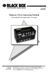
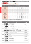
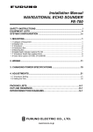
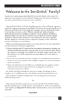
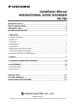
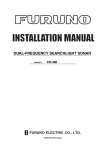
Back
MULTI-PURPOSE LCD DISPLAY
MU-150C
SAFETY INSTRUCTIONS
Safety Instructions for the Operator
Safety Instructions for the Installer
WARNING
WARNING
Do not open the equipment.
Do not open the cover
unless totally familiar with
electrical circuits and
service manual.
Only qualified personnel
should work inside
the equipment.
Improper handling can result
in electrical shock.
Do not disassemble or modify the
equipment.
Fire, electrical shock or serious injury can
result.
Turn off the power at the switchboard
before beginning the installation.
Use the proper fuse.
Fire or electrical shock can result if the
power is left on.
Fuse rating is shown on the equipment.
Use of a wrong fuse can result in damage
to the equipment.
Do not install the equipment where it
may get wet from rain or water splash.
Immediately turn off the power at the
switchboard if the equipment is emitting
smoke or fire.
Water in the equipment can result in fire,
electrical shock or damage to the equipment.
Continued use of the equipment can cause
fire or electrical shock. Contact a FURUNO
agent for service.
CAUTION
Ground the equipment to
prevent mutual interference.
CAUTION
Observe the following compass safe
distances to prevent interference to a
magnetic compass:
A warning label is attached to the
equipment. Do not remove the label.
If the label is missing or damaged,
contact a FURUNO agent or dealer.
WARNING
To avoid electrical shock, do not
remove cover. No user-serviceable
parts inside.
Name: Warning Label (2)
Type: 03-129-1001
Code No.: 100-236-741
MU-200C
Standard
compass
Steering
compass
1.55 m
1.05m
Locate the MU-150C out of direct sunlight for optimum viewing.
When lifting the display unit, hold it
together with the cover.
About the TFT LCD
Grasping by the cover alone may allow
the display unit to fall, resulting in
possible injury or damage to the equipment.
The TFT LCD is constructed using the
latest LCD techniques, and displays
99.99% of its pixels. The remaining 0.015%
of the pixels may drop out or blink, however this is not an indication of malfunction.
i
TABLE OF CONTENTS
FOREWORD ........................................................................................................ iii
SYSTEM CONFIGURATION................................................................................ iv
EQUIPMENT LISTS .............................................................................................. v
1 MOUNTING ...................................................................................................... 1
1.1 Display Unit ..................................................................................................................... 1
2 WIRING............................................................................................................. 7
2.1 Wiring External Equipment .............................................................................................. 7
3 ADJUSTMENTS ............................................................................................. 10
3.1 Picture Adjustment ........................................................................................................ 11
3.2 RGB Adjustment............................................................................................................ 12
3.3 Brilliance Adjustment ..................................................................................................... 12
4 OPERATION ................................................................................................... 13
5 MAINTENANCE, TROUBLESHOOTING ....................................................... 14
5.1 Maintenance.................................................................................................................. 14
5.2 Troubleshooting............................................................................................................. 15
APPENDIX
Modification for Switching from Landscape to Portrait Orientation ........ AP-1
SPECIFICATIONS........................................................................................... SP-1
PACKING LISTS
OUTLINE DRAWINGS
INTERCONNECTION DIAGRAM
ii
FOREWORD
A Word to the Owner of the MU-150C
FURUNO Electric Company thanks you for purchasing the MU-150C 15” Multi-Purpose
LCD Display. We are confident you will discover why the FURUNO name has become
synonymous with quality and reliability.
For over 50 years FURUNO Electric Company has enjoyed an enviable reputation for
quality and reliability throughout the world. This dedication to excellence is furthered by our
extensive global network of agents and dealers.
Your equipment is designed and constructed to meet the rigorous demands of the marine
environment. However, no machine can perform its intended function unless properly
installed and maintained. Please carefully read and follow the operation, installation and
maintenance procedures set forth in this manual.
We would appreciate feedback from you, the end-user, about whether we are achieving our
purposes.
Thank you for considering and purchasing FURUNO.
Features
• Main or remote display for radars, video sounders, sonars. Compatible equipment:
FR-1505 MK3 series, FR-1760DS, FCV-1200 series, FCV-1500 series, CH-250, CH-37,
CSH-23/73/83, GD/GP-280/380/680, etc.
• High resolution display of 1024 x 768 dot (XGA), 640 x 480 dot (VGA)
• Brightness of 180 cd/m2 (typical) and minimum 150 cd/m2 for comfortable viewing day
and night
• Landscape or portrait orientation
• Wide viewing angle of 160° for observation by more than one person
iii
SYSTEM CONFIGURATION
RGB
Radar, Video Plotter,
Navigator, Video Sounder,
Scanning Sonar, etc.
24 VDC or
100 - 240 VAC
Control unit of
Video Sounder
(e.g., FCV-1200 series)
NMEA 0183
Navigator (GPS, etc.)*
* = When using the FCV-1200 series or
CH-250, NMEA 0183 data may be output
to the MU-150C instead of the interface
unit.
Connectable equipment
MU-150C Display Unit Type
Equipment
Landscape
Portrait*
FR-1500 MK3 series
Yes
No
FCV-1200 series
Yes
Yes (Modification required)
FCV-1500 series
No
Yes (Modification required)
GD/GP-280/380/680
Yes
No
CH-250
Yes
No
CH-37
No
Yes (Modification required)
CSH-23/73/83
No
Yes
FR-1760DS
No
Yes (Modification required)
* = Display cannot be viewed with polarized sunglasses.
iv
EQUIPMENT LISTS
Standard supply
Name
Display Unit
Spare Parts *
Installation Materials *
Accessories *
Bracket *
Type
Code No.
Qty
−
1
MU-150C
Remarks
AC specification
DC specification
For DC
SP10-02801
001-414-460
SP10-02802
001-414-970
CP10-04910
001-414-690
CP10-04920
001-414-700
FP10-02501
001-414-490
1 set
FP10-05401
001-402-540
1
For FCV-1500L
FP10-02510
001-414-510
1
Including FP10-02511
Code No.
Qty
1 set
1 set
For AC
For AC (CP10-04901)
For DC (CP10-04902)
Option
Name
Type
Bracket *
FP10-02510
001-414-510
1
Hood (Landscape)
FP10-02502
001-414-730
1
Hood (Portrait)
FP10-02503
001-414-750
1
* = See packing list at end of manual.
v
Remarks
Including FP10-02511
1 MOUNTING
Refer to the outline drawing at the end of the manual for mounting dimensions.
Note: The LCD is made of glass. Handle it with care.
1.1 Display Unit
The display unit may be flush mounted in a panel or on a desktop, using the optional
bracket. Display tilt can be chosen from 9° or 20°, by the location of the mounting plate.
When selecting a mounting location, keep in mind the following points:
• Locate the unit out of direct sunlight.
• Select a location where the display can be easily viewed and the controls can be easily
operated.
• Leave sufficient space around the unit for servicing and maintenance. See the outline
drawing for recommended servicing space.
• The unit weighs 35.3 lbs (16 kg). Be sure the mounting location is strong enough to
support the weight of the unit.
• Locate the unit away from areas subject to water splash and rain.
Flush mounting
See the outline drawing at the end of the manual for mounting dimensions.
CAUTION
Hold the cover and display unit
together when lifting the display unit.
The display unit may fall if only the cover
is held.
1. Using the paper template supplied in the installation materials, make a cutout in the
mounting location. (Modification of the LCD may be necessary depending on equipment
used. See “Modification for Switching from Landscape to Portrait Orientation” in the
Appendix for details.)
2. Pull the display unit cover toward you to detach it.
1
See Note 2.
Cover
Display Unit
Display unit and cover
3. Fasten the display unit to the mounting location with six tapping screws (5X30).
Note 1: Hex head bolts may also be used to fasten the display unit. However, their
length must be at least 30 mm.
Note 2: Use M5 bolt or tapping screw (nominal diameter: M5), although the size of the
mounting holes in the display unit is M8.
384 ±0.5
333 ±0.5
366 ±1
315 ±1
15 ±0.5
100
333 ±0.5
315 ±1
384 ±0.5
82
366 ±1
45
15 ±0.5
259 ±0.5
259 ±0.5
Unit: mm
45
Mounting dimensions for landscape orientation
82
100
Unit: mm
Mounting dimensions for portrait orientation
Mounting dimensions
4. Reattach the cover.
5. For the portrait model only, attach the FURUNO logo seal (supplied in the accessories)
at the top left corner. Remove the logo seal from the bottom left corner.
2
Desktop mounting
The display unit can be mounted on a desktop, using the optional bracket (Type:
FP10-02510, Code No.: 001-414-510).
1. Fasten the mounting base (lower) to the mounting location with four sets of hex head
bolts, spring washers, flat washers and nuts.
Hex Head Bolt
Spring Washer
Flat Washer
Nut
FRONT
Mounting base (lower)
2. Fasten the bracket and mounting plate to the mounting base (upper) with 12 hex head
bolts. Fasten the mounting plate at the rear for 9° tilt, or at the front for 20° tilt.
Hanger
Hanger
Mounting Plate
Mounting Plate
Mounting Base
(upper)
Mounting Base
(upper)
REAR
FRONT
9 degree TILT
20 degree TILT
Fastening bracket and mounting plate to mounting base (upper)
3
3. Loosely screw six screws (M5X15) into the holes at the rear of the display unit. Set the
screws on the display unit to the holes on the bracket and then tighten the screws. (Note
that the display unit may also be mounted in portrait orientation.)
Fastening the front panel
4. Fasten the power cable (local supply in case of AC power), cable from the control and
operation sections of external equipment and ground wire (local supply) at the rear of
the MU-150C. For use of the cable type 06S4078 (from a control section), cut off the
connector’s rubber cover and remove the fixing metal to enable connection.
Cable from operation section
MJ-A10SPF0002
NMEA Cable from control section
06S4078 *5m*
Power Cable
Ground Wire
DISPLAY
UNIT
Connection of cables at the rear of the display unit
4
5. Grease the two hex head bolts for fastening the display unit to the mounting base
(lower).
6. Fasten the display unit to the mounting base (lower) with the two hex head bolts
greased at step 5.
Hex Head Bolt
Fastening the mounting base (lower) to the display unit
7. For portrait orientation, attach logo (supplied) at upper left hand corner.
5
1.1.1 Hood (option)
A hood (portrait or landscape) is optionally available. Attach it to the display unit with Velcro
tape as shown below.
1. Attach nine sets of Velcro tape to the display unit at the locations shown below, in as
straight as possible.
Attach
in line.
Attach
in line.
Display unit, how to attach Velcro tapes
2. Attach the hood to the display unit.
6
2 WIRING
2.1 Wiring External Equipment
Connect external equipment to the MU-150C by referring to the drawings in this section. A
cable with connector at both ends is provided to connect equipment.
General-purpose monitor
To use the MU-150C as a general-purpose monitor, connect equipment with a mini D-SUB
15P connector. In this case do not connect a navigator to the NMEA port. Nav data is output
through the D-SUB 25P connector.
CH-37: DISPLAY
CH-250: INTERFACE UNIT RGB OUT
FCV-1200 Series: INTERFACE UNIT RGB OUT
FCV-1500 Series: DISPLAY UNIT DISPLAY
Mini D-SUB
15P
GP/GD-280/380/680: DISPLAY UNIT EXT VIDEO
FR-1500 MK3 Series: Connector on RGB BUFFER
board in display unit
FR-1760DS: Connector on RGB BUFFER
board in display unit
24 VDC
or 100-240 VAC
Ground
Terminal
Display unit, rear view, wiring using general-purpose cables
Note: When connecting a general-purpose monitor, use the following cable or the
equivalent:
Mini D-sub 15P: EVNPS05-50 ft, male-male, (max. 15 m)
Manufacturer: BlackBox Japan
7
Connecting FCV-1200 series and CH-250
Using the cables designated below (or equivalent) to connect the FCV-1200 series or
CH-250 makes their interface unit of the FCV-1200 series and CH-250 unnecessary. The
mini D-SUB 15 P connector cannot be used to connect the FCV-1200 series and CH-250.
Navigator, etc.
06S4078
24 VDC
or 100-240 VAC
Ground
Terminal
MJ-A10SPF0002-015
FCV-1200 Series:
PROCESSOR UNIT CN1
CH-250: TRANSCEIVER UNIT
DATA/VIDEO OUT
FCV-1200 Series: CONTROL UNIT
CONT
CH-250: CONTROL UNIT
REM CONT
Display unit, rear view, wiring using specialty cables
Notes on wiring
• For AC specification, solder connector SRCN6A13-3S (supplied in installation materials)
to the power cable (DPYC-1.5 (Japan Industrial Standard) or equivalent).
Sheath
4-6 cm
m
3m
Armor
Solder Side
Screw
Armor
Clamp
12
Tighten
set screw
3
Connect to
"1" and "2".
Armor
Connector Housing
1: AC (L: Live line)
2: AC(N: Neutral line)
Armor
Conductor
S = 1.5 mm2
f = 1.56 mm
Sectional view of cable DPYC-1.5
Soldering connector SRCN6A13-3S
How to solder connector SRCN6A13-3S; sectional view of cable DPYC-1.5
•
The cover of the D-sub connector of the cable 06S4078 may be removed to pass the
cable through tubing, bulkhead, etc. Use vinyl tape to bind connector wiring and rubber
cover. This allows the cable to be passed through a hole having a diameter of 30 mm.
8
•
Cable 06S4078 is of waterproof construction, however, the MU-150C is not waterproof
(specification IPX0). Therefore, remove rubber cover and fixing metal from the display
side of the cable.
Remove fixing metal.
Remove rubber cover.
D-sub connector
9
3 ADJUSTMENTS
Controls for adjustment of the picture are provided on the rear of the display unit. Open the
small cover to access the controls.
1
POWER
2A
S1 S2 S3 S4
J16
1
J17
31
J18
31
2
3
GND
100-240 VAC
50-60 Hz
R1
R2
3 R3
J16
J17
J18
R1
R2
R3
DATA/VIDEO IN
CONT
NMEA
Rear panel (AC type)
10
EXTBRILL
BRILL
BRTP
R
G
B
S1
S2
S3
S4
SEL
UP
DOWN
RESET
3.1 Picture Adjustment
Contrast and picture are adjusted with
[S1]: Opens menu; selects menu items.
[S2]: Increases setting.
[S3]: Decreases setting.
[S4]: Initializes setting.
Note: Though “EXIT” is printed on the CONE Board (10P6877), the function of S4 switch is
“RESET.”
[S1]
Brilliance
(Not used.)
[S1]
Contrast
[S1]
Size (horizontal size for landscape type, vertical size
for portrait type)
[S1]
Geometry
[S1]
Center (vertical position for landscape type, horizontal
position for portrait type)
[S1]
Center (horizontal position for landscape type, vertical
position for portrait type)
[S1]
Press [S4] to
ALL RESET
P r e s s R e s e t K e y Initialize settings
Over 2Seconds.
[S1]
About the picture adjustment buttons
• The [S2] and [S3] buttons may be pressed and held down to increase/decrease setting
more rapidly.
• The [S4] button can initialize settings individually or all at once. Press it at after
adjustment of a specific setting, or at the “ALL RESET” screen to initialize all picture
adjustment settings.
• The adjustment display disappears if there is no adjustment within five seconds.
11
3.2 RGB Adjustment
Color may be adjusted with the following potentiometers. Turn the potentiometers clockwise
to increase color.
Model
FCV-1200 Series, CH-250,
FR-1760DS
GD/GP-280/380/680, FCV-1500
Series, CH-37, CSH23/73/83,
FR-1500 MK3 Series
Potentiometer Setting
Default setting
Fully clockwise
R1: Red
R2: Green
R3: Blue
3.3 Brilliance Adjustment
Brilliance can be adjusted from the control unit of the FCV-1200 series or CH-250 by setting
jumper block J17 as below.
J17: Brilliance control circuit selection
1-2: Brilliance is adjusted from the MU-150C (default setting)
2-3: Brilliance is adjusted from the control unit of the FCV-1200 series or CH-250
Note: Do not change the setting of the J16 or J18. The default setting for both is “1-2”.
S1
S2
J16
1
S3
J17
31
S4
J18
31
R1
J16
J17
J18
R1
R2
R3
R2
3 R3
Jumper blocks
12
EXTBRILL
BRILL
BRTP
R
G
B
S1
S2
S3
S4
SEL
UP
DOWN
RESET
4 OPERATION
FURUNO
LED
BRILLIANCE Control
POWER
Switch
Display unit
POWER switch:
Turns the power on/off. The LED lamp lights in green when the unit
is turned on and goes off when the unit is turned off.
To turn the MU-150C on and off from the control unit of a video
sounder such as the FCV-1200 series, turn on the POWER switch
of the MU-150C. Note that with the MU-150C turned on and the
FCV-1200 turned off the LED on the MU-150C lights in red. This
means that weak current is flowing to the MU-150C. To turn off the
power completely, turn off the MU-150C.
BRILLIANCE control: Adjusts display brilliance. In some instances brilliance is controlled
from the equipment connected (for example, FCV-1200 series).
LED:
Shows display status:
Green: Display on
Red:
Power save
13
5 MAINTENANCE,
TROUBLESHOOTING
WARNING
ELECTRICAL SHOCK HAZARD
Do not open the equipment.
Only qualified personnel
should work inside the
equipment.
5.1 Maintenance
Routine maintenance
Regular maintenance is important for good performance. Check the following on a regular
basis to keep the equipment in good operating condition.
• Check that the connectors at the rear of the display unit are tightly fastened.
• Check the ground wire and ground terminal for rust. Clean if necessary. Confirm that the
ground wire is tightly fastened.
• Remove dust and dirt from the display unit and LCD with a dry, soft cloth. Do not use
chemical cleaners to clean any part of the display unit – they can remove paint and
markings.
• Wipe the LCD carefully o prevent scratching, using tissue paper and an LCD cleaner. To
remove dirt or salt deposits, use an LCD cleaner, wiping slowly with tissue paper so as
to dissolve the dirt or salt. Change paper frequently so the salt or dirt will not scratch the
LCD. Do not use solvents such as thinner, acetone or benzene for cleaning.
Fuse replacement
The 1.5 A 250 V fuse (AC type) or 3A 125V fuse (DC type) on the rear panel protects the
equipment from internal fault and overcurrent. If the fuse blows, find the cause before
replacing it. If the fuse blows again after replacement, request service.
WARNING
Use the proper fuse.
Use of a wrong fuse can cause fire or
damage to the equipment.
14
5.2 Troubleshooting
The table below provides troubleshooting procedures to use when no picture appears. If
you cannot restore the picture, do not attempt to check inside the equipment – there are no
user serviceable parts inside. Refer any work to a qualified technician.
Troubleshooting table
Reason for no picture
Remedy
Battery voltage too high.
Check battery voltage.
Fuse has blown.
Replace fuse.
Cable between MU-150C and external
equipment has loosened.
Refasten cable.
Power cable has loosened.
Refasten cable.
15
APPENDIX
Modification for Switching from
Landscape to Portrait Orientation
To use the MU-150C for portrait with the CH-37, FCV-1200 series, FCV-1500 series or
FR-1760DS, the LCD assembly must be turned 180°.
1. Place the display unit on a workbench with the LCD side down. It is recommended to
place the unit on cushioning material so as not to place pressure on knob.
2. Unfasten the items marked with white arrows in the figure below to remove the cover for
the power section and connectors: 10 screws, four spacers for connectors and two nuts
of waterproof connectors. This gives access to the CONE Board (10P6877) and power
assy.
Display unit, rear view
3. Remove the 14 screws marked with gray arrows in the figure above.
AP-1
4. Referring to the arrows in the figure below for location, disconnect the connector and
four power switch tag terminals and release cable from CK clamp.
Note: When disconnecting the tag terminals, pull them by the metal part of the terminal.
Do not disconnect by pulling the cable – cables may become separated from the
terminal.
Power assy.
AP-2
5. Unfasten the eight screws marked with the arrows in the figure below.
Display unit, rear view
6. Release the cable from the clamp marked with the gray arrow in the figure above.
7. Turn the LCD assembly 180°.
POWER chassis
Display unit, rear view
8. Fasten screws unfastened at step 5. (Torque: 0.39 ±0.04 Nm; 4 ±0.4 kgm)
9. Turn the power chassis 180° counterclockwise, making sure no load is placed on the
cable at the center of the power chassis when turning. When reassembling the display
unit to “landscape,” turn the power chassis 180° clockwise. The tape for fixing the cable
from the LCD may peel off if the power chassis is turned twice or more in the same
direction.
10. Fasten the cable with the clamp marked with the gray arrow in step 6.
AP-3
11. Fasten cables with the clamps marked with the white arrows in the figure below.
Connect the power connector to J1 on the pcb 10P3879 as follows: 1, Brown; 3, Orange;
4, Purple, 6, White.
Location of power switch and pcb 10P3879
12. Fix the rear cover with 14 screws (M4 x 8). (Torque 1.47 ±0.15 Nm; 15 ±1.5 kgm)
13. Temporarily fasten the cover for the power section and connectors with 10 screws
(M3 x 8).
14. Fix four spacers for connectors. (Torque: 0.39 ±0.04 Nm; 4 ±0.4 kgm)
15. Temporarily fasten the cover for the power section and connectors with six screws
(M3 x 8). (Torque: 0.78 ±0.08 Nm; 8 ±0.8 kgm)
16. Fasten two waterproofing nuts. (Torque: 0.76 ±0.02 Nm; 7.8 ±0.2 kgm)
17. Fasten the cover near the power section and connectors with remaining four screws.
(Torque: 0.78 ±0.08 Nm; 8 ±0.8 kgm)
18. Attach the FURUNO logo (supplied) at the cavity in the upper left corner of the display
unit.
AP-4
SPECIFICATIONS OF MULTI-PURPOSE LCD DISPLAY
MU-150C
1 GENERAL
1.1 Display
15.0 inch color LCD, 304.1 x 228.1 mm
1.2 Brightness
180 cd/m2 typical, 150 cd/m2 minimum
1.3 Resolution
VGA (640 x 480), XGA (1024 x 768)
1.4 Viewing Angle
160° (left/right: 80°, up/down: 80°)
1.5 Input Signal
RGB: 0.7 Vp-p to 3.0 Vp-p, Synchronization: TTL level
2 POWER SUPPLY
2.1 Rated Voltage
100-240 VAC: 0.7-0.4 A, 1 phase, 50-60 Hz
24 VDC, 1.4 A
3 ENVIRONMENTAL CONDITIO N
3.1 Ambient Temperature
Operation: 0°C to +50°C, Storage: -20°C to +60°C
3.2 Relative Humidity
95% at 40°C
3.3 Waterproofing
IPX0
3.4 Vibration
IEC 60945
4 COATING COLOR
4.1 Main Unit
N3.0
SP - 1
E2025S01B
This page is intentionally left blank.
A-1
PACKING LIST
10CQ-X-9851 -5
1/1
MU-150C-H-DC-CS
N A M E
ユニット
O U T L I N E
DESCRIPTION/CODE №
Q'TY
UNIT
MU-150C-H-DC
15型カラーLCD表示器
1
MULTI-PURPOSE LCD DISPLAY
000-012-618
予備品
SPARE PARTS
SP10-02801
FGMB 3A 125V
ヒューズ
2
FUSE
000-104-909
付属品
ACCESSORIES
FP10-02501
10-075-1052-0
ロゴシート
1
LOGO SEAL
100-294-900
工事材料
INSTALLATION MATERIALS
CP10-04902
MJ-A3SPF0020-050Z
ケーブル組品MJ
1
CABLE ASSY.
000-145-882
その他工材
OTHER INSTALLATION MATERIALS
10-075-1071-2
装備用型紙
1
TEMPLATE
100-294-942
(略図の寸法は、参考値です。
DIMENSIONS IN DRAWING FOR REFERENCE ONLY.)
C2025-Z01-E
A - 1A
A-1A
PACKING LIST
10CQ-X-9855 -1
1/1
MU-150C-H-AC-CS
N A M E
ユニット
O U T L I N E
DESCRIPTION/CODE №
Q'TY
UNIT
MU-150C-H-AC
15型カラーLCD表示器
1
MULTI-PURPOSE LCD DISPLAY
000-012-617
予備品
SPARE PARTS
SP10-02802
FGMB 1.5A 250V
ヒューズ
2
FUSE
000-145-654
付属品
ACCESSORIES
FP10-02501
10-075-1052-0
ロゴシート
1
LOGO SEAL
100-294-900
工事材料
INSTALLATION MATERIALS
CP10-04901
SRCN6A13-3S
コネクタ(SRCN)
1
CONNECTOR
000-508-665
その他工材
OTHER INSTALLATION MATERIALS
10-075-1071-2
装備用型紙
1
TEMPLATE
100-294-942
(略図の寸法は、参考値です。
DIMENSIONS IN DRAWING FOR REFERENCE ONLY.)
C2025-Z05-A
A-2
Your Local Agent/Dealer
9-52 Ashihara-cho,
Nishinomiya 662-8580, JAPAN
Telephone :
0798-65-2111
Fax
0798-65-4200
:
All rights reserved.
Printed in Japan
FIRST EDITION : JAN
JAN.. 2002
C3
Pub. No. OME-20250
( YOTA ) MU-150C
: OCT.
OCT. 04, 2004
*00080923101*
*00080923101*
*00080923101*
*OME20250C30*
*OME20250C30*
*OME20250C30*