1
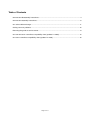
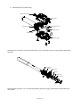
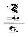
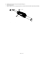
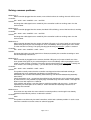
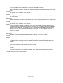
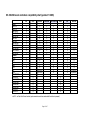
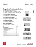
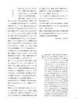
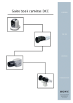
521-522-523-524 SERIES MANFROTTO ZOOM
CONTROLLERS SERVICE MANUAL
This manual covers following products:
– 522 – 522A – 522C – 522CA
–
523 – 523PRO
–
521 – 521PRO – 521P
–
522P
–
524AX – 524FN – 524CN
Information contained in this document is confidential and shall not be revealed to third parities without
written permission from Lino Manfrotto S.P.A.
Page 2 of 17
Table of Contents
522-523-524 disassembly instructions...................................................................................................4
522-523-524 assembly instructions.......................................................................................................6
521 series cable exchange...................................................................................................................11
Solving common problems...................................................................................................................12
Returning the goods to service center.................................................................................................14
521-522-523 zoom controllers compatibility chart (updated 11.2005).................................................15
524 zoom controllers compatibility chart (updated 11.2005)...............................................................16
Page 3 of 17
522-523-524 disassembly instructions
1. Remove the cable from 2.5 mm jack and unlock the screw found on the side of the collar (only 522
and 523 series)
Unscrew
Drawing 1: Disassembly of pan bar tube
2. Remove the collar along with the pan bar tube
3. Unscrew the four screws found on the bottom side of the controller and disassembly the body
4. Unscrew the hexagonal screw locking the spring housing
Unscrew
Unscrew
Zoom wheel
Spring housing
Drawing 2: Screws to untight
Page 4 of 17
5. Disassembly the controller body
Small tooth wheel
Top cover
Controller PCB
Spring housing
Pan bar tube
Zoom wheel
Bottom cover
Drawing 3: Controller body disassembly
Note for 524xx controllers: do not take the PCB out of the controller body as it is permanently attached to
the cable.
Spring housing
Spring Zoom wheel
Bearing
Bearing cover
Nylon washer
Orings
Drawing 4: Zoom wheel disassembly
Note for 522P controllers: you must first disassembly the power supply cable before disassembling the
zoom wheel.
Page 5 of 17
522-523-524 assembly instructions
1. Assembly spring housing as shown in Drawing 5
Pan bar tube
Spring housing
Spring
Hexagonal screw
Drawing 5: Assembling spring housing
Make sure to properly align the spring housing threaded hole with the positioning hole found in the pan
bar tube (see. Drawing 6)
Align the two holes
Drawing 6: Aligning spring housing
Pay attention to not to over tight the hexagonal screw as you may break the spring housing thread.
Page 6 of 17
2. Assembly zoom wheel – make sure to put some teflon grease on the bearing (Drawing see 7)
Bearing
Bearing cover
Oring
Zoom wheel
Nylon washer
Drawing see 7: Zoom wheel assembly
3. Assembly the controller body – follow Drawing 8 and Drawing 9
• Position bottom cover about 1 cm away from the zoom wheel (see. Drawing 9)
•
Make sure both orings are properly placed in the immersions found in the bottom cover
•
Insert the PCB into the top cover
•
Insert teeth wheel into the top cover
•
Put the top cover on top of the bottom one – the controller should look as in Drawing 9
Note for 522P controllers: before assembling both covers, you must first assembly back the power
supply cable and plug it into jack found on the controller PCB
Page 7 of 17
Top cover
Tooth wheel
Controller PCB
Bottom cover
Drawing 8: Controller body assembly
Leave approx. 1 cm of space between
zoom wheel and controller body
Nylon washer between tooth wheel
and top and bottom covers
Drawing 9: Controller body assemblied
4. Slide the controller body into the zoom wheel
• Make sure the teeth wheel is properly aligned with zoom wheel – both have special marks to help
you: one of the tooth of the small wheel is shorter (see Drawing 10), while the zoom wheel has an
arrow pointing into the place where the tooth should be placed (see Drawing 11)
Tooth wheel
position mark
Drawing 10: Small teeth wheel position mark
Page 8 of 17
Zoom wheel
position mark
Drawing 11: Zoom wheel position mark
•
Slide in the controller body into the zoom wheel
•
Turn the controller body left and right a bit to properly position it against pan bar tube – there is a
positioning pin found on the inside of the bottom cover which must be fitted into the hole found on
the bottom side of the pan bar tube (see Drawing 12)
Fix both covers with the four screws
•
Pan bar tube
Postioning hole
Postioning pin
Bottom cover
Drawing 12: Positioning pin and postioning hole
Page 9 of 17
5. Assembly the other part of the pan bar (see Drawing 12)
• Fix the locking screw
•
Plug the cable into 2.5 mm plug (except 524xx controllers where the cable is permanently attached)
Plug the cable
Fix the screw
Drawing 13: Final assembly
Page 10 of 17
521 series cable exchange
Cable
Cable collar screw
Cable collar
Drawing 14: 521 cable exchange
Page 11 of 17
Solving common problems
Malfunction 1:
When controller plugged into the camera, none of the functions is working, the main LED is not on
Controller:
522 – 522A – 523 – 523PRO – 521 – 521PRO
Solution:
Exchange the cable (repair set no. 522SCA), if the controller is still not working, return it to the
service center
Malfunction 2:
When controller plugged into the camera, the Main LED is blinking, none of the functions is working
Controller:
522 – 522A – 523 – 523PRO – 521 – 521PRO
Solution:
Exchange the cable (repair set no. 522SCA), if the controller is still not working, return it to the
service center
Malfunction 3:
When controller plugged into the camera, the Main LED goes on (in case of 522P one of the zoom
speed LEDs goes on), the camera begins to zoom immediately without pressing the zoom wheel,
no other function is working. The spring housing (see Drawing 3) is broken – plastic is cracked.
Controller:
522 – 522A – 523 – 523PRO – 522P – 524xx
Solution:
Exchange the broken part with repair kit no. R522,06, assembly the controller according to “522523-524 assembly instructions”
Malfunction 4:
When controller is plugged into the camera, the Main LED goes on (in case of 522P one of the
zoom speed LEDs goes on), the camera begins to zoom immediately without pressing the zoom
wheel, no other function is working. The spring housing (see Drawing 3) is not broken. Usually, the
zoom wheel is not working smoothly – you can feel sort of clicking when moving it.
Controller:
522 – 522A – 523 – 523PRO – 522P – 524xx
Solution:
This problem usually means that the controller was dropped and the small teeth wheel got
misaligned with zoom wheel gear (see Drawing 10 and Drawing 11).
Disassembly the controller and assembly back following "522-523-524 disassembly/assembly
instructions"
Check the bottom cover – sometimes the positioning pin (see Drawing 12) is mechanically broken
by misuse and it is not possible to properly align controller body with zoom wheel – exchange the
bottom cover with repair kit no. R522,02.
If this problem will repeat, it can also mean a machining problem with top cover – in this case
replace the part with repair set no. R522,01. Follow 522-523-524 assembly instructions” to
assembly the controller.
Malfunction 5:
Zoom does not stop when the zoom wheel is in neutral position, even though it was already
repaired as described in previous "malfunction solution"
Controller:
522P
Solution:
This problem considers only few 522P controllers, which had a software problem. In such a case
return the controller to service center, for software upgrade.
Page 12 of 17
Malfunction 6:
It is not possible to switch the camera on when it is in standby mode, or
It is not possible to put the camera into standby mode, or
When controller is plugged it switches the camera into standby mode without pressing the on/off
button.
Controller:
522 – 522A – 523 – 523PRO – 521 – 521PRO
Solution:
Exchange the cable (repair set no. 522SCA), if the controller is still not working properly, return it to
the service center.
Malfunction 7:
Most of the functions are working well, except one or two, e.g. push auto focus is not working with
Canon XL-2 camera.
Controller:
522 – 522A – 523 – 523PRO – 521 – 521PRO
Solution:
On most cases the controller is not broken. This usually means that the specific function is not
implemented with the specific camera. LANC commands are "interpreted" differently by different
cameras. Please check the "compatibility chart" for the functions compatibility with the specific
camera. If you are sure that the specific function should work, but it is not please return the
controller to the service center. When returning please indicate the type of the camera and function
which is not working.
Malfunction 8:
Controller does not work when plugged into Sony DSR-250 – the LED is blinking.
Controller:
523 – 523PRO – 521 – 521PRO
Solution:
The problem related to old controllers – exchange for the brand new on, or sent to service center
for upgrade. When returning please indicate that the problem is related to the SONY DSR-250
camera.
Malfunction 9:
A part of the controller is mechanically broken by misuse.
Controller:
all types
Solution:
Use appropriate repair kit to repair the controller. Follow assembly/disassembly instructions.
In all other cases return to the service center.
Page 13 of 17
Returning the goods to service center
In order to receive fast and problem – free service, please follow the rules when returning broken controllers
to the service center:
• Please always return with filled "REMOTE CONTROLLER REPAIR FORM"
•
Sent to address: "ZPUH Ventis s.c. Sienkiewicza 48, 42-600 Tarnowskie Góry POLAND"
•
If you are sending the broken controller from outside the EU, attach a pro-forma invoice and write
for each controller: "Zoom controller sample" – unit price 5 USD. Write in the invoice "Product
samples value for custom purposes only". Do not indicate anywhere, that it is returned for repair.
The overall invoice value must not exceed 20 USD. - lower unit price, if necessary.
Page 14 of 17
521-522-523 zoom controllers compatibility chart (updated 11.2005)
521
SONY
HVR-A1U
HVR-Z1U
DSR-PDX10
DSR-PD170
DSR-PD150
DSR-250
DSR-200
DCR-VX2100
DCR-VX2000
DCR-VX1000
DCR-TRV950
DCR-PC330
CANON
XL-H1
XM-1
GL-1
XM-2
GL-2
XL1
XL1s
PANASONIC
AG-HVX200
AG-DVX100BE
AG-DVX100B
AG-DVX100E
AG-DVX100A
AG-DVC80
AG-DVC30
521P
521PRO
522/522A
522C/522CA
X
X
X
X
X
X
X
X
X
X
X
X
X
X
X
X
X
X
X
X
X
X (no PAF)
X
X
X
X
X
X
X
X
X
X
X
X
X
X
X
X
X
X
X
X
X
X (no PAF)
X
X
X
X
X (no PAF)
X (no PAF)
522P
523
523PRO
X
X
X
X
X
X
X
X
X
X
X
X
X
X
X
X
X
X
X
X
X
X
X
X
X
X
X
X
X
X
X
X
X
X (no PAF)
X
X
X
X
X
X
X
X
X
X
X
X
X
X
X
X
X (no PAF)
X
X
X
X
X (no PAF)
X (no PAF)
X
X
X
X
X
X
X
X
X
X
X
X
X
X
no PAF – no Push Auto Focus function (puts camera into auto focus mode while the button is pressed)
Page 15 of 17
524 zoom controllers compatibility chart (updated 11.2005)
Lenses Model
YH12x4.8 IRS-A/KRS-A
YH19x6.7 IRS / KRS
YJ12x6.5B IRS/KRS
YJ13x6B IRS/KRS
YH18x6.7IRS/KRS
YJ18x9B IRS/KRS
YJ19x9B IRS/KRS
YJ20x8.5B KRS
YH16x7 KRS
HJ40x10B IASD-V
HJ40x14B IASD-V
HJ22ex7.6B IRSE/IA SE
HJ21ex7.5B IRSE/IA SE
HJ21ex7.8B IRSD/IA SD
HJ17ex7.7B IRSE/IA SE
HJ17ex7.6B IRSE/IA SE
HJ11ex4.7B IRSE/IA SE
J35ex11B IA SD
J35ex15B IA SD
J33ax11B IA SD
J33ax15B IA SD
J22ex7.6B IRSE/IA SE
J17ex7.7B IRCE/IASE
J11ex4.5B IRSE/IA SE
12x5.3 AIF.HR
15x8.3 AIF.HR
HA 42x9.7ERD
HA 42x13.5ERD
HA 36x10.5 ERD
HA 25X16.5BERD
HA 22X7.8ERM/ERD*
HA 22X7.3ERM/ERD*
HA 18x7.6ERM/ERD*
HA 13X4.5ERM/ERD*
HA 25X11.5BERD
HSs18X5.5BRD
HA 13X4.5BRD/PF*
HA 22X7.3RD/PF*
S20x6.4RM
S20x6.4ERM
S17x6.6 RM
S13X4.6RM
S13X4.6ERM
A20x8.6RM
A20x8.6ERM
A13X6.3RM
A17x9 RM
A13X6.3ERM
A36x14.5 ERD*
A36x10.5 ERD*
A22x7.8 ERM/ERD*
A22x7.8 DERM/DERD*
A18x7.6ERM/ERD*
A18x7.6DERM/DERD*
A13x4.5ERM/ERD*
A13x4.5DERM/DERD*
A42x9.7 ERD*
A42x13.5 ERD*
Lenses Type
Manfrotto products applicable
Manufacturer
Pro-video
Pro-video
Pro-video
Pro-video
Pro-video
Pro-video
Pro-video
Pro-video
Pro-video
HDTV ENG/EFP
HDTV ENG/EFP
HDTV ENG/EFP
HDTV ENG/EFP
HDTV ENG/EFP
HDTV ENG/EFP
HDTV ENG/EFP
HDTV ENG/EFP
SDTV ENG/EFP
SDTV ENG/EFP
SDTV ENG/EFP
SDTV ENG/EFP
SDTV ENG/EFP
SDTV ENG/EFP
SDTV ENG/EFP
Video SDTV ENG/EFP
Video SDTV ENG/EFP
HDTV ENG/EFP
HDTV ENG/EFP
HDTV ENG/EFP
HDTV ENG/EFP
HDTV ENG/EFP
HDTV ENG/EFP
HDTV ENG/EFP
HDTV ENG/EFP
HDTV ENG/EFP
HDTV ENG/EFP
HDTV ENG/EFP
HDTV ENG/EFP
Professional ENG/EFP
Professional ENG/EFP
Professional ENG/EFP
Professional ENG/EFP
Professional ENG/EFP
Professional ENG/EFP
Professional ENG/EFP
Professional ENG/EFP
Professional ENG/EFP
Professional ENG/EFP
Broadcast ENG/EFP
Broadcast ENG/EFP
Broadcast ENG/EFP
Broadcast ENG/EFP
Broadcast ENG/EFP
Broadcast ENG/EFP
Broadcast ENG/EFP
Broadcast ENG/EFP
Broadcast ENG/EFP
Broadcast ENG/EFP
524CN
524CN
524CN
524CN
524CN
524CN
524CN
524CN
524CN
524CN
524CN
524CN
524CN
524CN
524CN
524CN
524CN
524CN
524CN
524CN
524CN
524CN
524CN
524CN
524AX
524AX
524FN with 524ADAPT
524FN with 524ADAPT
524FN with 524ADAPT
524FN with 524ADAPT
524FN with 524ADAPT
524FN with 524ADAPT
524FN with 524ADAPT
524FN with 524ADAPT
524FN with 524ADAPT
524FN with 524ADAPT
524FN with 524ADAPT
524FN with 524ADAPT
524FN
524FN
524FN
524FN
524FN
524FN
524FN
524FN
524FN
524FN
524FN with 524ADAPT
524FN with 524ADAPT
524FN with 524ADAPT
524FN with 524ADAPT
524FN with 524ADAPT
524FN with 524ADAPT
524FN with 524ADAPT
524FN with 524ADAPT
524FN with 524ADAPT
524FN with 524ADAPT
Canon
Canon
Canon
Canon
Canon
Canon
Canon
Canon
Canon
Canon
Canon
Canon
Canon
Canon
Canon
Canon
Canon
Canon
Canon
Canon
Canon
Canon
Canon
Canon
A ngenieux
A ngenieux
Fujinon
Fujinon
Fujinon
Fujinon
Fujinon
Fujinon
Fujinon
Fujinon
Fujinon
Fujinon
Fujinon
Fujinon
Fujinon
Fujinon
Fujinon
Fujinon
Fujinon
Fujinon
Fujinon
Fujinon
Fujinon
Fujinon
Fujinon
Fujinon
Fujinon
Fujinon
Fujinon
Fujinon
Fujinon
Fujinon
Fujinon
Fujinon
Please note: We made every effort to make sure that information contained herein is correct and accurate, but we shall take no
liability for any errors or omissions.
Page 16 of 17
Cod. 522,50 – 01/06
Copyright © 2006 Manfrotto Bassano Italy