1
ORDER NO.DSC1203009CE
B26
Digital Camera
Model No. DMC-TZ27EB
DMC-TZ27EC
DMC-TZ30EB
DMC-TZ30EE
DMC-TZ30EF
DMC-TZ30EG
DMC-TZ30EP
DMC-TZ30GA
DMC-TZ30GC
DMC-TZ30GN
DMC-TZ30SG
DMC-TZ31EG
DMC-ZS19P
DMC-ZS20P
DMC-ZS20PC
DMC-ZS20PU
DMC-ZS20GH
DMC-ZS20GK
DMC-ZS20GT
Colours
(S)....................Silver Type (except DMC-TZ27EB/EC,
TZ30EE/EF/GN/SG, ZS19P, ZS20GT)
(K)....................Black Type
(R)....................Red Type (except DMC-TZ27EB/EC,
TZ30EP, ZS19P, ZS20GH/GK/GT)
© Panasonic Corporation 2012.
Unauthorized copying and distribution is a violation
of law.
(T)....................Brown Type (except DMC-TZ27EB/EC,
TZ30EB/SG, ZS19P, ZS20P/PC/PU)
(W)....................White Type (except DMC-TZ27EB/EC,
TZ30EE/GC, ZS19P, ZS20PC/PU/GH)
TABLE OF CONTENTS
PAGE
1 Safety Precautions -----------------------------------------------3
1.1. General Guidelines ----------------------------------------3
1.2. Leakage Current Cold Check ---------------------------3
1.3. Leakage Current Hot Check (See Figure 1)---------3
1.4. How to Discharge the Capacitor on Flash
P.C.B.----------------------------------------------------------4
2 Warning --------------------------------------------------------------5
2.1. Prevention of Electrostatic Discharge (ESD)
to Electrostatic Sensitive (ES) Devices ---------------5
2.2. How to Recycle the Lithium Ion Battery (U.S.
Only)-----------------------------------------------------------5
2.3. How to Replace the Lithium Battery -------------------6
3 Service Navigation------------------------------------------------8
3.1. Introduction --------------------------------------------------8
3.2. Service Navigation -----------------------------------------8
3.3. General Description About Lead Free Solder
(PbF) ----------------------------------------------------------9
3.4. How to Define the Model Suffix (NTSC or PAL
model)------------------------------------------------------- 10
4 Specifications ---------------------------------------------------- 16
5 Location of Controls and Components------------------ 18
6 Service Mode ----------------------------------------------------- 20
6.1. Error Code Memory Function ------------------------- 20
7 Troubleshooting Guide---------------------------------------- 24
7.1. Checking Method of GPS failure (Except:
TZ27EB/EC, ZS19P and 20GK)---------------------- 24
8 Service Fixture & Tools --------------------------------------- 26
8.1. Service Fixture and Tools ------------------------------ 26
8.2. When Replacing the Main P.C.B. -------------------- 26
8.3. Service Position ------------------------------------------ 27
9 Disassembly and Assembly Instructions --------------- 28
9.1. Disassembly Flow Chart-------------------------------- 28
9.2. P.C.B. Location ------------------------------------------- 28
9.3. Disassembly Procedure -------------------------------- 29
9.4. Lens Disassembly Procedure ------------------------- 36
9.5. Assembly Procedure for Lens (Revised
Version) ----------------------------------------------------- 40
9.6. Removal of the CMOS Unit---------------------------- 48
10 Measurements and Adjustments -------------------------- 49
10.1. Introduction ------------------------------------------------ 49
10.2. Before Disassembling the unit ------------------------ 49
10.3. Details of Electrical Adjustment----------------------- 51
10.4. After Adjustment------------------------------------------ 55
11 Maintenance ------------------------------------------------------ 56
11.1. Cleaning Lens, Viewfinder and LCD Panel -------- 56
12 Block Diagram --------------------------------------------------- 57
12.1. Overall Block Diagram ---------------------------------- 57
12.2. System Control Block Diagram ----------------------- 58
12.3. Audio/Video Process/ HDMI Block Diagram ------ 59
PAGE
12.4. Sensor Block Diagram --------------------------------- 60
12.5. Lens Drive Block Diagram----------------------------- 61
12.6. Power Block Diagram----------------------------------- 62
13 Wiring Connection Diagram -------------------------------- 63
13.1. Interconnection Schematic Diagram ---------------- 63
2
1 Safety Precautions
1.1.
General Guidelines
1.3.
1. IMPORTANT SAFETY NOTICE
There are special components used in this equipment
which are important for safety. These parts are marked by
2.
3.
4.
5.
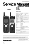
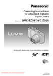
1. Plug the AC cord directly into the AC outlet. Do not use
an isolation transformer for this check.
2. Connect a 1.5kΩ, 10 W resistor, in parallel with a 0.15μF
capacitor, between each exposed metallic part on the set
and a good earth ground, as shown in Figure 1.
3. Use an AC voltmeter, with 1 kΩ/V or more sensitivity, to
measure the potential across the resistor.
4. Check each exposed metallic part, and measure the
voltage at each point.
5. Reverse the AC plug in the AC outlet and repeat each of
the above measurements.
6. The potential at any point should not exceed 0.75 V RMS.
A leakage current tester (Simpson Model 229 or
equivalent) may be used to make the hot checks, leakage
current must not exceed 1/2 mA. In case a measurement
is outside of the limits specified, there is a possibility of a
shock hazard, and the equipment should be repaired and
rechecked before it is returned to the customer.
in the Schematic Diagrams, Circuit Board Layout,
Exploded Views and Replacement Parts List. It is
essential that these critical parts should be replaced with
manufacturer's specified parts to prevent X-RADIATION,
shock fire, or other hazards. Do not modify the original
design without permission of manufacturer.
An Isolation Transformer should always be used during
the servicing of AC Adaptor whose chassis is not isolated
from the AC power line. Use a transformer of adequate
power rating as this protects the technician from
accidents resulting in personal injury from electrical
shocks. It will also protect AC Adaptor from being
damaged by accidental shorting that may occur during
servicing.
When servicing, observe the original lead dress. It a short
circuit is found, replace all parts which have been
overheated or damaged by the short circuit.
After servicing, see to it that all the protective devices
such as insulation barriers, insulation papers shields are
properly installed.
After servicing, make the following leakage current
checks to prevent the customer from being exposed to
shock hazards.
1.2.
Leakage Current Hot Check
(See Figure 1)
Leakage Current Cold Check
1. Unplug the AC cord and connect a jumper between the
two prongs on the plug.
2. Measure the resistance value, with an ohmmeter,
between the jumpered AC plug and each exposed
metallic cabinet part on the equipment such as
screwheads, connectors, control shafts, etc. When the
exposed metallic part has a return path to the chassis, the
reading should be between 1MΩ and 5.2MΩ. When the
exposed metal does not have a return path to the chassis,
Figure 1
the reading must be infinity.
3
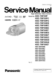
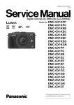
1.4.
How to Discharge the Capacitor on Flash P.C.B.
CAUTION:
1. Be sure to discharge the capacitor on Flash P.C.B.
2. Be careful of the high voltage circuit on Flash P.C.B. when servicing.
[Discharging Procedure]
1. Refer to the disassemble procedure and remove the necessary parts/unit.
2. Install the insulation tube onto the lead part of Resistor (ERG5SJ102:1kΩ /5W).
(an equivalent type of resistor may be used.)
3. Place a resistor between both terminals of capacitor on the Flash P.C.B. for approx. 5 seconds.
4. After discharging, confirm that the capacitor voltage is lower than 10V using a voltmeter.
Fig. F1
4
2 Warning
2.1.
Prevention of Electrostatic Discharge (ESD) to Electrostatic Sensitive
(ES) Devices
Some semiconductor (solid state) devices can be damaged easily by static electricity. Such components commonly are called
Electrostatically Sensitive (ES) Devices.
The following techniques should be used to help reduce the incidence of component damage caused by electrostatic discharge
(ESD).
1. Immediately before handling any semiconductor component or semiconductor-equipped assembly, drain off any ESD on your
body by touching a known earth ground. Alternatively, obtain and wear a commercially available discharging ESD wrist strap,
which should be removed for potential shock reasons prior to applying power to the unit under test.
2. After removing an electrical assembly equipped with ES devices, place the assembly on a conductive surface such as
aluminum foil, to prevent electrostatic charge buildup or exposure of the assembly.
3. Use only a grounded-tip soldering iron to solder or unsolder ES devices.
4. Use only an antistatic solder removal device. Some solder removal devices not classified as
can
generate electrical charge sufficient to damage ES devices.
5. Do not use freon-propelled chemicals. These can generate electrical charges sufficient to damage ES devices.
6. Do not remove a replacement ES device from its protective package until immediately before you are ready to install it. (Most
replacement ES devices are packaged with leads electrically shorted together by conductive foam, aluminum foil or
comparable conductive material).
7. Immediately before removing the protective material from the leads of a replacement ES device, touch the protective material
to the chassis or circuit assembly into which the device will be installed.
CAUTION:
Be sure no power is applied to the chassis or circuit, and observe all other safety precautions.
8. Minimize bodily motions when handling unpackaged replacement ES devices. (Otherwise harmless motion such as the
brushing together of your clothes fabric or the lifting of your foot from a carpeted floor can generate static electricity (ESD)
sufficient to damage an ES device).
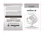
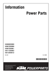
2.2.
How to Recycle the Lithium Ion Battery (U.S. Only)
5
2.3.
2.3.1.
How to Replace the Lithium Battery
Replacement Procedure
1. Remove the Top P.C.B. (Refer to Disassembly Procedures.)
2. Remove the Lithium battery (Ref. No.
at foil side of Top P.C.B.) and then replace it into new one.
Note:
The lithium battery is a critical component.
(Type No.: ML-421S/DN Manufactured by Energy Company, Panasonic Corporation.)
It must never be subjected to excessive heat or discharge.
It must therefore only be fitted in equipment designed specifically for its use.
Replacement batteries must be of the same type and manufacture.
They must be fitted in the same manner and location as the original battery, with the correct polarity contacts observed.
Do not attempt to re-charge the old battery or re-use it for any other purpose.
It should be disposed of in waste products destined for burial rather than incineration.
6
Note:
Above caution is applicable for a battery pack which is for DMC-TZ27/TZ30/TZ31/ZS19/ZS20 series, as well.
7
3 Service Navigation
3.1.
Introduction
This service manual contains technical information, which will allow service personnel's to understand and service this model.
Please place orders using the parts list and not the drawing reference numbers.
If the circuit is changed or modified, the information will be followed by service manual to be controlled with original service manual.
3.2.
Service Navigation
3.2.1.
About lens block
The image sensor (CMOS) unit which are connected to the lens unit with 3 screws. 2 of these 3 screws are locked with the screw
locking glue, after performing the Optical tilt adjustment. During servicing, if one of CMOS fixing screws are loosened, the Optical tilt
adjustment must be performed.(About the Optical tilt adjustment, refer to the "10.3.2 Adjustment Specifications" for details.)
NOTE:
It is necessary to use the "DSC_Tilt" software to allow the "Optical tilt adjustment".
he Adjustment software "DSC_Tilt" is available at "TSN Website". To download, click on "Support Information from NWBG/
VDBG-AVC".
8
3.2.2.
About VENUS ENGINE (IC6001) < Located on the Main P.C.B. >
• The VENUS ENGINE (IC6001) consists of two IC chips, which are fixed together with solder.
(It is so called, "Package On Package" type of IC.)
Caution:
• During servicing, do not press down hard on the surface of IC6001.
3.3.
General Description About Lead Free Solder (PbF)
The lead free solder has been used in the mounting process of all electrical components on the printed circuit boards used for this
equipment in considering the globally environmental conservation.
The normal solder is the alloy of tin (Sn) and lead (Pb). On the other hand, the lead free solder is the alloy mainly consists of tin
(Sn), silver (Ag) and Copper (Cu), and the melting point of the lead free solder is higher approx.30 °C (86 °F) more than that of the
normal solder.
Definition of PCB Lead Free Solder being used
The letter of
is printed either foil side or components side on the P.C.B. using the lead free solder.
(See right figure)
Service caution for repair work using Lead Free Solder (PbF)
• The lead free solder has to be used when repairing the equipment for which the lead free solder is used.
•
•
•
•
(Definition: The letter of
is printed on the P.C.B. using the lead free solder.)
To put lead free solder, it should be well molten and mixed with the original lead free solder.
Remove the remaining lead free solder on the P.C.B. cleanly for soldering of the new IC.
Since the melting point of the lead free solder is higher than that of the normal lead solder, it takes the longer time to melt the
lead free solder.
• Use the soldering iron (more than 70W) equipped with the temperature control after setting the temperature at 350±30 degrees
C (662±86 °F).
Recommended Lead Free Solder (Service Parts Route.)
• The following 3 types of lead free solder are available through the service parts route.
RFKZ03D01KS-----------(0.3mm 100g Reel)
RFKZ06D01KS-----------(0.6mm 100g Reel)
RFKZ10D01KS-----------(1.0mm 100g Reel)
Note:
* Ingredient: tin (Sn) 96.5%, silver (Ag) 3.0%, Copper (Cu) 0.5%, Cobalt (Co) / Germanium (Ge) 0.1 to 0.3%
9
3.4.
How to Define the Model Suffix (NTSC or PAL model)
There are nine kinds of DMC-TZ27/TZ30/TZ31/ZS19/ZS20, regardless of the colours.
• a) DMC-TZ30 (Japan domestic model.) /SG
• b) DMC-ZS20P/PC
• c) DMC-ZS19P
• d) DMC-TZ27EB/EC, TZ30EB/EE/EF/EG/EP, TZ31EG
• e) DMC-TZ30EE
• f ) DMC-ZS20GT
• g) DMC-TZ30GN
• h) DMC-ZS20GK
• i ) DMC-TZ30GA/GC, ZS20PU/GH
What is the difference is that the "INITIAL SETTINGS" data which is stored in Flash ROM mounted on Main P.C.B.
3.4.1.
Defining methods
To define the model suffix to be serviced, refer to the nameplate which is putted on the bottom side of the Unit.
10
Note:
After replacing the Main P.C.B., be sure to achieve adjustment.
The Maintenance software (DIAS) is available at "software download" on the "Support Information from NWBG/VDBG-AVC"
web-site in "TSN system".
11
3.4.2.
INITIAL SETTINGS:
After replacing the Main P.C.B., make sure to perform the initial settings after achieving the adjustment by ordering the following
procedure in accordance with model suffix of the unit.
1. IMPORTANT NOTICE:
Before proceeding Initial settings, be sure to read the following CAUTIONS.
2. PROCEDURES:
• Precautions: Read the above "CAUTION 1" and "CAUTION 2", carefully.
• Preparation:
1. Attach the Battery or AC Adaptor with a DC coupler to the unit.
2. Set the mode dial to the PROGRAM AE mode.
Note: If the mode dial position is other than PROGRAM AE mode, it does not display the initial settings menu.
• Step 1. The temporary cancellation of "INITIAL SETTINGS":
Set the REC/PLAYBACK selector switch to "REC (Camera mark)".
While keep pressing "UP of Cursor button" and MOTION PICTURE button simultaneously, turn the Power SW on.
• Step 2. The cancellation of "INITIAL SETTINGS":
Set the REC/PLAYBACK selector switch to "PLAYBACK".
Press "UP of Cursor button" and MOTION PICTURE button simultaneously, then turn the Power SW off.
• Step 3. Turn the Power on:
Set the REC/PLAYBACK selector switch to "REC (Camera mark)", and then turn the Power SW on.
12
• Step 4. Display the "INITIAL SETTINGS" menu:
Note: If the unit is other than PROGRAM AE mode, it does not display the initial settings menu.
While keep pressing MENU/SET and "RIGHT of Cursor button" simultaneously, turn the Power SW off.
The "INITIAL SETTINGS" menu is displayed.
There are two kinds of "INITIAL SETTINGS" menu form as follows:
[CASE 1. After replacing MAIN P.C.B.]
There are four kinds of menu from as follows:
[Except for "DMC-TZ30EG, EF, EB and EP" models : (VEP56159A is used as a Main P.C.B.)]
When Main P.C.B. has just been replaced, all of the model suffix are displayed as follows. (Four pages in total)
[Only for "DMC-TZ30EG, EF, EB, EP and TZ31EG" models : (VEP56159B is used as a Main P.C.B.)]
When Main P.C.B. has just been replaced, the following model suffix are displayed as follows. (Two pages in total)
To display the "TZ31" model suffix, choose the "EG" area and press the DELETE button.
[Only for "DMC-TZ27EB and EC" models : (VEP56159C is used as a Main P.C.B.)]
When Main P.C.B. has just been replaced, the following model suffix are displayed as follows. (Two pages in total)
[Only for "DMC-ZS19P and ZS20GK" models : (VEP56159D is used as a Main P.C.B.)]
When Main P.C.B. has been replaced, the following model suffix are displayed as follows. (Four pages in total)
13
[CASE 2. Other than "After replacing Main P.C.B."]
14
• Step 5. Chose the model suffix in "INITIAL SETTINGS": (Refer to "CAUTION 1")
[Caution: After replacing Main P.C.B.]
(Especially, other than "DMC-TZ30EG/EF/EB/EP, TZ31EG and DMC-TZ27EB/EC" models : (VEP56159A/D is used as a
Main P.C.B.))
The model suffix can be chosen, JUST ONE TIME.
Once one of the model suffix have been chosen, the model suffix lists will not be displayed, thus, it can not be changed.
Therefore, select the area carefully.
Select the area with pressing "UP / DOWN of Cursor buttons".
• Step 6. Set the model suffix at "INITIAL SETTINGS":
Press the "RIGHT of Cursor buttons".
The only set area is displayed. Press the "RIGHT of Cursor buttons" after confirmation.
(The unit is powered off automatically.)
• Step 7. CONFIRMATION:
Confirm the display of "PLEASE SET THE CLOCK" in concerned language when the unit is turned on again.
When the unit is connected to PC with USB cable, it is detected as removable media.
1) As for your reference, major default setting condition is as shown in the following table.
Default setting (After "INITIAL SETTINGS")
a)
b)
c)
d)
e)
f)
g)
h)
i)
j)
k)
l)
m)
n)
o)
p)
q)
r)
s)
t)
MODEL
DMC-TZ30 (Japan domestic model)
DMC-TZ27EB
DMC-TZ27EC
DMC-TZ30EB
DMC-TZ30EE
DMC-TZ30EF
DMC-TZ30EG
DMC-TZ30EP
DMC-TZ30GA
DMC-TZ30GC
DMC-TZ30GN
DMC-TZ30SG
DMC-TZ31EG
DMC-ZS19P
DMC-ZS20P
DMC-ZS20PC
DMC-ZS20PU
DMC-ZS20GH
DMC-ZS20GK
DMC-ZS20GT
VIDEO OUTPUT
NTSC
PAL
PAL
PAL
PAL
PAL
PAL
PAL
PAL
PAL
PAL
PAL
PAL
NTSC
NTSC
NTSC
NTSC
PAL
PAL
NTSC
LANGUAGE
Japanese
English
English
English
Russian
French
English
English
English
English
English
English
English
English
English
English
Spanish
English
Chinese (simplified)
Chinese (Traditional)
15
DATE
Year/Month/Date
Date/Month/Year
Date/Month/Year
Date/Month/Year
Date/Month/Year
Date/Month/Year
Date/Month/Year
Date/Month/Year
Date/Month/Year
Date/Month/Year
Date/Month/Year
Date/Month/Year
Date/Month/Year
Month/Date/Year
Month/Date/Year
Month/Date/Year
Month/Date/Year
Date/Month/Year
Year/Month/Date
Year/Month/Date
REMARKS
No Underwater mode.
4 Specifications
16
Note:
*Above specification is for DMC-ZS20P. Some of the specification may differ depends on model suffix.
[1] Only for "EB/EF/EG/EP" models:
1). [Interface Digital:]
• Data form the PC can not be written to the camera using the USB connection cable.
[2] Others:
1). [Analog video/audio:]
NTSC ----------------------------------------------------------(Only "P/PC/PU/GT/GD" models)
NTSC/PAL Composite (Switched by menu) ----------(Except "P/PC/PU/GT/GD" models)
2). [GPS:]
• DMC-TZ27EB/EC, ZS19P and ZS20GK do not equipped with GPS function.
17
5 Location of Controls and Components
18
19
6 Service Mode
6.1.
Error Code Memory Function
1. General description
This unit is equipped with history of error code memory function, and can be memorized 16 error codes in sequence from the
latest. When the error is occurred more than 16, the oldest error is overwritten in sequence.
The error code is not memorized when the power supply is shut down forcibly (i.e.,when the unit is powered on by the battery,
the battery is pulled out) The error code is memorized to Flash ROM when the unit has just before powered off.
2. How to display
The error code can be displayed by ordering the following procedure:
• Preparation:
1. Attach the Battery to the unit.
2. Set the mode dial to the PROGRAM AE mode.
Note:
*Since this unit has built-in memory, it can be performed without inserting SD memory card.
• Step 1. The temporary cancellation of "INITIAL SETTINGS":
Set the REC/PLAYBACK selector switch to "REC (Camera mark)".
While keep pressing "UP of Cursor button" and MOTION PICTURE button simultaneously, turn the Power SW on.
• Step 2. Execute the error code display mode:
Press the "LEFT of Cursor button", MENU/SET button and MOTION PICTURE button simultaneously.
The display is changed as shown below when the above buttons are pressed simultaneously.
Normal display → Error code display → CAMERA INFO → Normal display → .....
20
3. Error Code List
The error code consists of 8 bits data and it shows the following information.
Attribute
LENS
Main item
Sub item
Lens drive OIS
Error code
High 4bits Low 4 bits
18*0
1000
2000
3000
4000
5000
6000
7000
Zoom
(C.B.)
0?10
0?20
0?30
0?40
0?50
0?60
Focus
0?01
0?02
Lens
18*1
0000
18*2
0000
Contents (Upper)
Check point (Lower)
PSD (X) error. Hall element (X axis) position detect
error in OIS unit.
OIS Unit
PSD (Y) error. Hall element (Y axis) position detect
error in OIS unit.
OIS Unit
GYRO (X) error. Gyro (IC7101) detect error on Main
P.C.B.
IC7101 (Gyro element) or IC6001 (VENUS ENGINE)
GYRO (Y) error. Gyro (IC7101) detect error on Main
P.C.B.
IC7101 (Gyro element) or IC6001 (VENUS ENGINE)
MREF error (Reference voltage error).
IC9101 (LENS drive) or IC6001 (VENUS ENGINE)
Drive voltage (X) error.
LENS Unit, LENS flex breaks, IC6001(VENUS
ENGINE) AD value error, etc.
Drive voltage (Y) error.
LENS Unit, LENS flex breaks, IC6001(VENUS
ENGINE) AD value error, etc.
Collapsible barrel Low detect error
(Collapsible barrel encoder always detects High.)
Mechanical lock, FP9005-(11) signal line or IC6001
(VENUS ENGINE)
Collapsible barrel High detect error
(Collapsible barrel encoder always detects Low.)
Mechanical lock, FP9005-(11) signal line or IC6001
(VENUS ENGINE)
Zoom motor sensor error.
Mechanical lock, FP9005-(6), (9) signal line or
IC6001 (VENUS ENGINE)
Zoom motor sensor error. (During monitor mode.)
Mechanical lock, FP9005-(6), (9) signal line or
IC6001 (VENUS ENGINE)
Zoom motor sensor error. (During monitor mode with
slow speed.)
Mechanical lock, FP9005-(6), (9) signal line or
IC6001 (VENUS ENGINE)
Phase error or operation failure of zoom Lens/motor/
encoder. (IMPACT)
Mechanical lock, zoom encoder.
HP High detect error
(Focus encoder always detects High, and not
becomes Low)
Mechanical lock, FP9005-(11) signal line or IC6001
(VENUS ENGINE)
HP Low detect error
(Focus encoder always detects Low, and not
becomes High)
Mechanical lock, FP9005-(11) signal line or IC6001
(VENUS ENGINE)
Power ON time out error.
Lens drive system
Power OFF time out error.
Lens drive system
21
Error Indication
Detecting
Part/Circuit
device
OIS X
LENSu NG
OIS Y
GYRO X
GYRO NG
GYRO Y
OIS REF
LENSSd/DSP
NG
OISX REF
LENSu/LENS
FPC
OISY REF
ZOOM L
ZOOMm/
LENSu
ZOOM H
ZOOM ENC
FOCUS L
LENS FPC/
DSP
FOCUS H
LENS DRV
LENSu
Attribute
HARD
Main item
Sub item
Error code
High 4bits Low 4 bits
Adj.History OIS
19*0
VENUS
A/D
FLASH
ROM
(EEPROM
Area)
Flash
28*0
FLASH
ROM
(EEPROM
Area)
2B*0
2000
3000
4000
5000
6000
7000
8000
9000
A000
B000
C000
D000
E000
0000
0001
0003
0004
0002
0005
SOFT
SYSTEM
RTC
2C*0
CPU
Reset
30*0
Card
Card
31*0
0008
0009
0001
0001
|
0007
0001
0002
0004
CPU,
Stop
ASIC hard
39*0
38*0
0005
0001
0002
0100
0200
3A*0
0300
0008
Operation Power on
3B*0
0000
Zoom
3C*0
0000
35*0
35*1
0000
|
FFFF
0000
35*2
0000
Memory
area
Zoom
Contents (Upper)
Check point (Lower)
OIS adj. Yaw direction amplitude error (small)
OIS adj. Pitch direction amplitude error (small)
OIS adj. Yaw direction amplitude error (large)
OIS adj. Pitch direction amplitude error (large)
OIS adj. MREF error
OIS adj. time out error
OIS adj. Yaw direction off set error
OIS adj. Pitch direction off set error
OIS adj. Yaw direction gain error
OIS adj. Pitch direction gain error
OIS adj. Yaw direction position sensor error
OIS adj. Pitch direction position sensor error
OIS adj. other error
Flash charging error.
IC6001-(AC18) signal line or Flash charging circuit
EEPROM read error
IC6001 (Flash ROM)
Error Indication
Detecting
Part/Circuit
device
OIS ADJ
OIS ADJ
STRB CHG
FROM RE
STRB PCB/
FPC
FROM
EEPROM write error
FROM WR
FROM
IC6001 (Flash ROM)
Firmware version up error
(No indication) (No indication)
Replace the firmware file in the SD memory card.
SDRAM error
SDRAM Mounting defective
SYSTEM IC initialize failure error
SYS INIT
MAIN PCB
Communication between IC6001 (VENUS ENGINE)
and IC9101 (SYSTEM)
NMI RST
MAIN PCB
NMI reset
Non Mask-able Interrupt
(30000001-30000007 are caused by factors)
Card logic error
SD CARD
SD CARD/
DSP
SD memory card data line or IC6001 (VENUS
ENGINE)
Card physical error
SD memory card data line or IC6001 (VENUS
ENGINE)
Write error
SD WRITE
SD memory card data line or IC6001 (VENUS
ENGINE)
Format error
INMEMORY
FROM
Camera task finish process time out.
LENS COM
LENSu/DSP
Communication between Lens system and IC6001
(VENUS ENGINE)
Camera task invalid code error.
DSP
DSP
IC6001 (VENUS ENGINE)
File time out error in recording motion image
IC6001 (VENUS ENGINE)
File data cue send error in recording motion image
IC6001 (VENUS ENGINE)
Single or burst recording brake time out.
work area partitioning failure
(No indication) (No indication)
USB dynamic memory securing failure when
connecting
Flash ROM processing early period of camera during
INIT
(No indication)
movement.
Imperfect zoom lens processing
ZOOM
ZOOMm/
LENSu
Zoom lens
Software error
DSP
DSP
(0-7bit : command, 8-15bit : status)
Though record preprocessing is necessary, it is not
called.
Though record preprocessing is necessary, it is not
completed.
22
(No indication) (No indication)
Important notice about "Error Code List"
1) About "*" indication:
The third digit from the left is different as follows.
+.In case of 0 (example: 18 0 01000)
When the third digit from the left shows "0", this error occurred under the condition of INITIAL SETTINGS has been completed.
It means that this error is occurred basically at user side.
+.In case of 8 (example: 18 8 01000)
When the third digit from the left shows "8", this error occurred under the condition of INITIAL SETTINGS has been released.
(Example; Factory assembling-line before unit shipment, Service mode etc.)
It means that this error is occurred at service side.
2) About "?" indication: ("18*0 0?01" to "18*0 0?50"):
The third digit from the right shows one of the hexadecimal ("0" to "F") character.
4. How to exit from Error Code display mode:
Simply, turn the power off. (Since Error code display mode is executed under the condition of temporary cancellation of "INITIAL
SETTINGS", it wake up with normal condition when turn off the power.)
Note:
The error code can not be initialized.
23
7 Troubleshooting Guide
7.1.
Checking Method of GPS failure (Except: TZ27EB/EC, ZS19P and 20GK)
1. GENERAL DESCRIPTION
Note:
DMC-TZ27EB/EC, ZS19P and ZS20GK do not equipped with GPS function.
24
2. Checking flowchart of GPS failure.
The checking flowchart of GPS failure is as follows:
Note:
*Perform the GPS communication test, even if the repair being carried out is not related with GPS function.
*The GPS function in this unit is performed communication between GPS P.C.B. (on the Top P.C.B.) and VENUS ENGINE
(IC6001: on the Main P.C.B.).
25
8 Service Fixture & Tools
8.1.
Service Fixture and Tools
The following Service Fixture and tools are used for checking and servicing this unit.
8.2.
When Replacing the Main P.C.B.
After replacing the Main P.C.B., be sure to achieve adjustment.
The Maintenance software (DIAS) is available at "software download" on the "Support Information from NWBG/VDBG-AVC" website in "TSN system".
26
8.3.
Service Position
This Service Position is used for checking and replacing parts. Use the following Extension cables for servicing.
No.
1
2
3
Parts No.
VFK1895
RFKZ0545
VFK1906
8.3.1.
Connection
PP9006 (MAIN P.C.B.) - PS9201 (OPERATION P.C.B.)
PP9901 (TOP P.C.B.) - PS9904 (Main P.C.B.)
PP8001 (FLASH P.C.B.) - PS9903 (TOP P.C.B.)
Form
40PIN B to B
34PIN B to B
20PIN B to B
Extension Cable Connections
CAUTION-1. (When servicing Flash P.C.B.)
1. Be sure to discharge the capacitor on Flash P.C.B.
Refer to "HOW TO DISCHARGE THE CAPACITOR ON Flash P.C.B.".
The capacitor voltage is not lowered soon even if the AC Cord is unplugged or the battery is removed.
2. Be careful of the high voltage circuit on Flash P.C.B.
3. DO NOT allow other parts to touch the high voltage circuit on Flash P.C.B.
27
9 Disassembly and Assembly Instructions
9.1.
Disassembly Flow Chart
9.2.
P.C.B. Location
28
9.3.
Disassembly Procedure
No.
Item
1 Rear Case Unit
2
Front Case Unit
3
4
Side Ornament R, Side
Ornament L Unit
Operation P.C.B.
5
LCD Unit
6
Frame Plate Unit
7
Lens Unit
8
Main P.C.B.
9
Top Case Unit
10 Top P.C.B.
11 Flash Unit, Flash P.C.B.
12 Battery Case
Fig.
Removal
Fig. D1 4 screws (A)
1 screw (B)
Rear Case Unit
Fig. D2 1 screw (C)
1 Locking tab
Front Case Unit
Fig. D3 Side Ornament R, Side
Ornament L Unit
Fig. D4 FP9202 (Flex)
FP9203 (Flex)
PS9201 (Connector)
Operation P.C.B.
Note:(When replacing
Operation P.C.B.)
Operation Sheet
Fig. D5 1 Locking tab
LCD Unit
Fig. D6 3 screws (D)
2 Locking tabs
Frame Plate Unit
Fig. D7 FP9001 (Flex)
FP9005 (Flex)
PCB Spacer
2 FPC Tapes
Lens Unit
Fig. D8 1 screw (E)
1 Locking tab
DPR Sheet
Main P.C.B.
Fig. D9 4 Locking tabs
Top Case Unit
Fig. D10 1 screw (F)
2 Locking tabs (A)
1 Locking tab (B)
4 Locking tabs (C)
FP9902 (Flex)
Flash Spacer
Earth Plate R
Top P.C.B.
Note:(When replacing Top
P.C.B.)
DPR Sheet (GPS)
Top AF Sheet
Fig. D12 3 Locking tabs
Flash Unit, Flash P.C.B.
Fig. D13 3 Locking tabs (A)
1 Locking tab (B)
Battery Case
29
9.3.1.
Removal of the Rear Case Unit
9.3.2.
Removal of the Front Case Unit
Fig. D2
9.3.3.
Removal of the Side Ornament R,
Side Ornament L Unit
Fig. D1
Fig. D3
30
9.3.4.
Removal of the Operation P.C.B.
9.3.5.
Removal of the LCD Unit
Fig. D5
Fig. D4
31
9.3.6.
Removal of the Frame Plate Unit
9.3.7.
Removal of the Lens Unit
Fig. D6
Fig. D7
32
9.3.8.
Removal of the Main P.C.B.
9.3.9.
Removal of the Top Case Unit
Fig. D9
Fig. D8
33
9.3.10. Removal of the Top P.C.B.
Fig. D10
Fig. D11
34
9.3.11.
Removal of the Flash Unit, Flash
P.C.B.
9.3.12. Removal of the Battery Case
Fig. D13
Fig. D12
35
9.4.
Lens Disassembly Procedure
9.4.1.
Removal of the Master Flange Unit
1. Unscrew the 6 screws (A).
2. Remove the Connector (20p).
3. Remove the Master Flange Unit and Drive Gear.
Precaution:
1. Do not remove the CMOS when disassembling or reassembling the lens in order to maintain it clean.
When remove it, refer to item "9.6".
2. Keep dust or dirt away from the lens.
3. To remove dirt or dust from the lens, blow with dry air.
4. Do not touch the lens surface.
5. Use lens cleaning KIT (BK)(VFK1900BK).
6. Apply grease (RFKZ0472) as shown on "THE
APPLICATION OF GREASE METHOD" in the figure.
7. Apply a light coat of grease using an object similar to a
toothpick.
36
9.4.2.
Removal of the Drive Frame Unit,
Decorative Frame Unit, Outside
Cam Frame, 1st Lens Frame Unit,
2nd Lens Frame Unit, 3rd Lens
Frame Unit, Straight Frame and
Both Side Cam Frame
9.4.3.
Removal of the Decorative Frame
Unit, Outside Cam Frame, 1st Lens
Frame Unit, 2nd Lens Frame Unit,
3rd Lens Frame Unit, Straight
Frame and Both Side Cam Frame
1. Turn the Outside Cam Frame in the arrow (2) direction,
and then align the mark (Drive Frame and Outside
Cam Frame).
2. Push the 1st Lens Frame Unit in the arrow (2) direction
from the front of the Lens, and remove the Unit of
Decorative Frame Unit, Outside Cam Frame, 1st Lens
Frame Unit, 2nd Lens Frame Unit, 3rd Lens Frame Unit,
Straight Frame and Both Side Cam Frame from the Drive
Frame Unit.
1. Turn the Fix Cam Frame Unit in the arrow (1) direction,
and align the mark (Fix Cam Frame and Outside Cam
Frame and Drive Frame).
2. Push the 1st Lens Frame Unit in the arrow (2) direction
from the front of the Lens, and then remove the Unit of
Drive Frame Unit, Decorative Frame Unit, Outside Cam
Frame, 1st Lens Frame Unit, 2nd Lens Frame Unit, 3rd
Lens Frame Unit, Straight Frame and Both Side Cam
Frame from the Fix Cam Frame Unit.
37
9.4.4.
Removal of the Outside Cam
Frame, 1st Lens Frame Unit, 2nd
Lens Frame Unit, 3rd Lens Frame
Unit, Straight Frame and Both Side
Cam Frame
9.4.5.
Removal of the 1st Lens Frame
Unit, 2nd Lens Frame Unit, 3rd
Lens Frame Unit, Straight Frame
and Both Side Cam Frame
• Hold the Both Side Cam Frame and turn it in the arrow
direction. Align the mark (Outside Cam Frame and Both
Side Cam Frame), and then remove the Unit of 1st Lens
Frame Unit, 2nd Lens Frame Unit, 3rd Lens Frame Unit,
Straight Frame and Both Side Cam Frame from the Outside
Cam Frame.
• Turn the Decorative Frame Unit in the arrow (1) direction,
and remove the Unit of Outside Cam Frame, 1st Lens Frame
Unit, 2nd Lens Frame Unit, 3rd Lens Frame Unit, Straight
Frame and Both Side Cam Frame from the Decorative
Frame Unit in the arrow (2) direction.
9.4.6.
Removal of the 1st Lens Frame Unit
• Turn the 1st Lens Frame Unit in the arrow (1) direction a
little, and remove the Unit of 2nd Lens Frame Unit, 3rd Lens
Frame Unit, Straight Frame and Both Side Cam Frame in the
arrow (2) direction.
38
9.4.7.
Removal of the 2nd Lens Frame
Unit
9.4.8.
1. Hold the Straight Frame and turn it in the arrow (1) so that
the mark (2nd Lens Frame Unit) meets the mark
(Straight Frame).
2. Pushing the 3rd Lens Frame Unit in the arrow (2)
direction from the front of the Lens, turn it in the arrow (3)
direction.
Removal of the 3rd Lens Frame
Unit
• Push the 3rd Lens Frame Unit in the arrow direction from the
front of the Lens, and remove the 3rd Lens Frame Unit from
the Straight Frame and Both Side Cam Frame.
9.4.9.
Removal of the Straight Frame
• Turn the Straight Frame in the arrow direction, and align the
mark (Straight Frame and Both Side Cam Frame) in the
direction as below.
Align the Bayonet Key with the Bayonet Inlet, and remove
the Straight Frame from the Both Side Cam Frame.
39
9.5.
9.5.1.
Assembly Procedure for Lens (Revised Version)
Insert the Straight Frame
Insert the Straight Frame into the Both Side Cam Frame as below.
(The phase difference between the two
*The
marks is about 90 degrees.)
mark of the Straight Frame is under the Shading Sheet.
Insert the Bayonet Key of the Straight Frame into the Bayonet Inlet of the Both Side Cam Frame.
(Pass the convexity of Bayonet Inlet through the concavity of Bayonet Key.)
Turn the Straight Frame about 90 degrees in the arrow direction so that the
mark of Straight Frame comes
close to the
mark of Both Side Cam Frame.
*As the drawing below indicates, align the Grooves of Straight Frame with the one of Both Side Cam Frame.
40
9.5.2.
Insert the 3rd Lens Frame Unit and the 2nd Lens Frame Unit
Insert the 3rd Lens Frame Unit as the drawing below indicated.
*Align the Stepping Motor of the 3rd Lens Frame Unit with the
mark of the Straight Frame Unit,
then put the each Cam Pin of the 3rd Lens Frame Unit in the each Groove of the Straight Frame Unit.
Insert the 2nd Lens Frame Unit as the drawing below indicated.
*Align the
mark of the 2nd Lens Frame Unit with the one of the Straight Frame Unit,
then put the each Cam Pin of the 2nd Lens Frame Unit in the each Groove of the Straight Frame Unit.
41
While pushing the 3rd Lens Frame Unit and the 2nd Lens Frame Unit, turn the Straight Frame Unit in the arrow direction to the
end.(about 30 degree)
*Need to confirm that the two Lens Frames move smoothly when the Straight Frame Unit rotates in two directions.
42
9.5.3.
Insert the 1st Lens Frame Unit and the Outside Cam Frame Unit
Insert the 1st Lens Frame as the drawing below indicated.
Pass the Cam Pin of the "LEICA" side of the 1st Lens Frame Unit through the Area of Cam Pin Insertion near the
Side Cam Frame Unit
mark of Both
1. Move the
mark of the Both Side Cam Frame Unit closer to the mark of the Outside Cam Frame Unit, then turn the 1st
Lens Frame Unit just a bit in the arrow direction.(about 2 degrees)
*Hold the Cam Pin of the Both Side Frame Unit close to the Straight Key of the Straight Frame Unit.
2. Insert the Straight Key and the Cam Pin into the following grooves.
(1)The Straight Key of the Straight Unit -> The groove for the Straight key of the Outside Cam Frame Unit
(2)The Cam Pin of the Both Side Cam Frame Unit -> The groove for the Cam Pin of the Outside Cam Frame Unit
43
Turn the Both Side Cam Frame Unit to the end in the arrow direction while holding the Outside Cam Frame Unit.
(About 118.5 degrees)
*Confirm that 1st Lens Frame Unit does not rotate when the Both Side Cam Frame Unit rotates.
(It's the confirmation that previous insertion is done normally.)
44
9.5.4.
Insert the Decorative Frame Unit
4. Turn the Decorative Frame Unite in the arrow (2) direction
1. Hold the Straight Key (Both Side Cam Frame), turn it in
the arrow direction and align with the Straight Key
(Outside Cam Frame).
so that the
mark (Decorative Frame) meets the
mark (Outside Cam Frame).
2. Insert 2 toothpicks (rotation stopper) in the position as
below.
3. Align the
mark (Decorative Frame) with the Straight
Key (Both Side Cam Frame), and install the Unit of
Outside Cam Frame,1st Lens Frame Unit, 2nd Lens
Frame Unite, 3rd Lens Frame Unite, Straight Frame and
Both Side Cam Frame to the Decorative Frame Unit.
45
9.5.5.
Insert the Drive Frame Unit
9.5.6.
Insert the Fix Frame Unit
1. Install the Drive Gear to the Fix Cam Frame Unit.
• Align the
mark (Drive Frame and Outside Cam Frame),
and install the Unit of Decorative Frame Unit, Outside Cam
Frame, 1st Lens Frame Unit, 2nd Lens Frame Unite, 3rd
Lens Frame Unit, Straight Frame and Both Side Cam Frame
to the Drive Frame Unit.
*Keep the toothpicks (rotation stopper ) inserted.
2. Align the
mark (Outside Cam Frame and Drive Frame
and Fix Cam Frame), and install the Unit of Drive Frame
Unit, Decorative Frame Unit, Outside Cam Frame, 1st
Lens Frame Unit, 2nd Lens Frame Unite, 3rd Lens Frame
Unit, Straight Frame and Both Side Cam Frame to the Fix
Cam Frame Unit.
*Keep the toothpicks (rotation stopper ) inserted.
3. Remove the toothpicks (rotation stopper) and insert the
Drive Gear.
46
9.5.7.
Insert the Master Flange Unit
5. Join the Zoom Motor Unit to the Boss, and install to the
Fix Cam Frame.
Note: (When Installing)
Refer to “The Application of Grease Method” when installing
the Master Flange Unit.
Take Care not to damage the flex.
Take Care not to tuck in to the Master Flange Unit, When
inserting the Shutter Flex.
1. Turn the Drive Frame Unit to the Wide position as below.
2. Push the Hole of the Shutter Flex to the Boss of the
Master Flange Unit tightly.
3. Place the Shutter Flex following the Guide of the Fix Cam
Frame, and install the Master Flange Unit to the Unit of
Fix Cam Frame Unite, Drive Frame Unit, Decorative
Frame Unit, Outside Cam Frame, 1st Lens Frame Unit,
2nd Lens Frame Unite, 3rd Lens Frame Unit, Straight
Frame and Both Side Cam Frame.
4. Turn the Drive Frame Unit to the completely retracted
position.
47
9.6.
Removal of the CMOS Unit
When remove the CMOS Unit once (the Torx screw (A) is
loosened even a little), the optical tilt adjustment is
required.
When loosen the Torx screw (A), necessary the optical tilt
adjustmentat the end of assembling. (Refer to item
"10.3.2.")
To prevent the CMOS Unit from catching the dust and dirt,
do not remove the CMOS Unit except for replacing.
48
10 Measurements and Adjustments
10.1. Introduction
When servicing this unit, make sure to perform the adjustments necessary based on the part(s) replaced.
Before disassembling the unit, it is recommended to back up the camera data stored in flash-rom as a data file.
IMPORTANT NOTICE (After replacing the Main P.C.B.)
After replacing the Main P.C.B., it is necessary to use the "DIAS" software to allow the release of adjustment flag(s).
The Adjustment software "DIAS" is available at "TSN Website". To download, click on "Support Information from NWBG/VDBGAVC".
*DIAS (DSC Integrated Assist Software)
10.2. Before Disassembling the unit
10.2.1. Initial Setting Release
The cameras specification are initially set in accordance with model suffix (such as EB, EG, GK, GC, and so on.).
Unless the initial setting is not released, an automatic alignment software in the camera is not able to be executed when the
alignment is carried out.
Note:
The initial setting should be again done after completing the alignment. Otherwise, the camera may not work properly.
Therefore as a warning, the camera display a warning symbol " ! " on the LCD monitor every time the camera is turned off.
Refer to the procedure described in "3.4.2. INITIAL SETTINGS" for details.
[How to Release the camera initial setting]
Preparation:
Attach the Battery to the unit.
Set the recording mode dial to PROGRAM AE mode.
Step 1. Temporary cancellation of "INITIAL SETTINGS":
Set the REC/PLAYBACK selector switch to "REC" (Camera mark).
While pressing the UP of Cursor button and MOTION PICTURE button simultaneously, turn the Power SW on.
Step 2. Cancellation of "INITIAL SETTINGS":
Set the REC/PLAYBACK selector switch to "PLAYBACK".
While pressing UP of Cursor button and MOTION PICTURE button simultaneously. (The camera will beep after this.)
Turn the Power off. (The warning symbol " ! " is displayed on the LCD monitor.)
49
10.2.2. Flash-Rom Data Backup
When trouble occurs, it is recommended to backup the Flash-rom data before disassembling the unit.
There are two kinds of Flash-rom data backup methods:
[ROM_BACKUP (Method of Non-PC backup)]
1. Insert the SD-card into the camera.
2. Set the camera to "Temporary cancellation of the initial
settings".
3. Select the "SETUP" menu.
From the "SETUP" menu, select "ROM BACKUP".
Note:
This item is not listed on the customer's "SET UP"
menu.
4. When this "ROM_BACKUP" item is selected, the
following submenus are displayed.
[DSC Integrated Assist Software (Method of Using PC)]
Same as TATSUJIN software for previous models.
10.2.3. Light Box
If using VFK1164TDVLB Light Box, remove the lens connection
ring by loosing three hexagon screws.
50
10.3. Details of Electrical Adjustment
10.3.1. How to execute the Electrical Adjustment
It is not necessary to connect the camera to a PC to perform adjustments.
"Flag reset operation" and "Initial setting operation" are required when carrying out the alignment, follow the procedure below.
10.3.1.1. Startup Electrical Adjustment mode
1. Release the initial settings.
2. Insert a recordable SD card.
(Without a SD card, the automatic adjustment can not
executed.)
3. Procedure to set the camera into adjustment mode:
a. Set the mode into PROGRAM AE mode.
b. Set the REC/PLAYBACK selector switch to "REC"
(Camera mark).
c. Turn the Power SW off.
d. Turn the Power SW on pressing MOTION PICTURE
and MENU/SET simultaneously.
LCD monitor displays "SERVICE MODE".
(Refer to Fig.F3-1)
Fig. 3-1
10.3.1.2. Status Adjustment Flag Setting
Reset (Not yet adjusted) the status flag condition.
1. After pressing the DISPLAY button, the LCD monitor
displays the Flag status screen (Refer to Fig.3-2.)
2. Select item by pressing the cross keys. (Gray cursor is
moved accordingly.)
3. Press the DELETE button.
Note:
The selected item's flag has been changed from
"F (green)" to "0 (yellow)".
*(Refer to Fig. 3-3)
*Flag conditions:
F (green)
means that the alignment has been completed and the
status flag condition is set. In this case, the flag condition
should be reset, if you try to carry out the automatic
alignment.
0 (yellow)
means that the alignment has been not "completed" and
the status flag condition is "reset". In this case, automatic
alignment is available.
Fig. 3-2
Fig. 3-3
• In case of setting the status flag into set condition again without completion of the alignment, the status flag should be SET by
using PC, or UNDO by using ROM BACKUP function.
51
10.3.1.3. Execute Adjustment
1. Perform step "10.3.1.1." to "10.3.1.2.", to reset the OIS
flag status "F" (Set) to "0" (Reset).
2. Press DISPLAY button after Flag reset.
OIS Adjustment screen is displayed on the LCD panel.
(Refer to Fig.3-4)
3. Press the shutter button. The adjustment will start
automatically.
4. When the adjustment is completed successfully,
adjustment report menu appears with Green OK on the
LCD monitor. (Refer to Fig.3-5)
Fig. 3-4
Fig. 3-5
10.3.1.4. Attention point during Adjustment
1. Step "10.3.1.3." procedure shows OIS adjustment as an
example. To perform the adjustment, refer to the "10.3.2.
Adjustment Specifications" table which shows key point
for each adjustment.
2. Do not move the light box, the camera or the chart while
adjusting. If one of these is moved accidentally, start the
adjustment again.
3. Do not press any buttons/keys until the default menu
(Fig.3-6) is displayed on the LCD monitor. Otherwise,
adjustment data may not be stored properly.
4. If the adjustment is interrupted accidentally, the alignment
data may not be properly saved in the Flash-rom.
Fig. 3-6
10.3.1.5. Finalizing the Adjustment
1. Several adjustment flags can be reset ("F" into "0") at the same time. In this case, when the adjustment has been completed,
the screen will change showing the adjustment for the next item until all reset items are completed.
Also, when the shutter button is pressed, the screen jump to the next adjustment item.
2. To cancel the adjustment mode while in the process of performing the adjustment, follow this procedures.
(1) Press "Right of cross key" button.
Note:
*.If adjustment is cancelled with above procedure, adjustment is not completed. Make sure to adjust it later.
*.Adjustment software "DIAS" is able to control the status of the adjustment flags.
52
10.3.2. Adjustment Specifications
The following matrix table shows the relation between the replaced part and the Necessary Adjustment.
When a part is replaced, make sure to perform the necessary adjustment(s) in the order indicated.
The table below shows all the information necessary to perform each adjustment.
53
n IMPORTANT NOTICE (After replacing the Main P.C.B.)
After replacing the Main P.C.B., make sure to perform the
"INITIAL SETTINGS" first, then release the "INITIAL
SETTINGS" in order to proceed the electrical adjustment.
Note:
1. If electrical adjustment or data re-writing is executed
before "INITIAL SETTINGS", suffix code list is never
displayed, and it cannot be chosen suitable suffix code.
2. Never remove the battery during initial setting in process.
54
10.4. After Adjustment
10.4.1. Initial Setting
Since the initial setting has been released to execute the built-in adjustment software, it should be set up again before shipping the
camera to the customer.
Refer to the procedure described in "3.4.2. INITIAL SETTINGS" for details.
[IMPORTANT]
1. The initial setting should be done again after completing the alignment. Otherwise, the camera will not work properly.
Therefore as a warning, the camera display a warning symbol " ! " on the LCD monitor every time the camera is turned off.
2. Confirm that status of all adjustment flag show "F". Even if one of the adjustment flag shows "0", initial setting programmed is
never executed.
3. Adjustment software "DIAS" is able to control the status of the adjustment flags.
The Adjustment software "DIAS" is available at "TSN Website", therefore, access to "TSN Website" at "Support Information
from NWBG/VDBG-AVC".
55
11 Maintenance
11.1. Cleaning Lens, Viewfinder and LCD Panel
Do not touch the surface of lens, Viewfinder and LCD Panel with your hand.
When cleaning the lens, use air-Blower to blow off the dust.
When cleaning the LCD Panel, dampen the lens cleaning paper with lens cleaner, and the gently wipe the their surface.
Note:
The Lens Cleaning KIT; VFK1900BK(Only supplied as 10 set/Box) is available as Service Aid.
56
12 Block Diagram
12.1. Overall Block Diagram
(24mm - 480mm)
IC6005
IC3101
MOS
FLASH ROM
/1Gbit
1/2.33" 14.2 MEGA PIX
ZOOM
IRIS
SHUTTER
OIS UNIT
FOCUS
(27MHz)
SD
CARD
HDMI
TERMINAL
IC9101
MOTOR DRIVE,
OIS DRIVE &
PRE PROCESS
MICROPHONE (Lch)
IC9101
VIDEO OUT &
AUDIO AMP
IC7101
GYRO
SENSOR
MICROPHONE (Rch)
MICROPHONE AMP
SPEAKER
SPEAKER CONTROL
IC6001
VENUS ENGINE, SDRAM
PRE/CAMERA PROCESS
J-PEG COMP/EXPAND
MEDIA I/F
USB I/F
MAIN MICROPROCESSOR
OIS CONTROL
MOS DRIVE
LENS DRIVE
LCD DRIVE
SDRAM/2Gbit
IC8101
FLASH CONTROL
FLASH
GPS UNIT
DIGITAL/AV OUT
TERMINAL
QR9301,QR9302
TOUCH PANEL
CONTROL CIRCUIT
REAR OPERATION UNIT
TOUCH PANEL
COLOUR LCD
PANEL
3.0" PANEL
460K PIX
(Type of LCD Driver inclusion)
IC9101
SYSTEM IC
X9101
(32.768kHz)
IC1501
CHARGE IC
IC1502
USB SW
USB
TOP OPERATION UNIT
IC1001
POWER
X6001
(24MHz)
BATTERY
(POWER SUPPLY)
DMC-TZ27/TZ30/TZ31, ZS19/ZS20 OVERALL BLOCK DIAGRAM
57
12.2. System Control Block Diagram
IC6001
(VENUS ENGINE)
OPERATION P.C.B.
PP9006 PS9201
6
6
CROSS KEY IN C10
IC9101
DOWN
UP
S9203
S9202
S9201
2
1
2
1
2
1
2
1
4
3
4
3
4
3
4
3
POWER SW ON H
POWER SW ON AB21
SHUTTER HALF
SHUT HALF AC13
EXPOSURE
DELETE
DISPLAY
MENU
S9210
S9208
S9207
S9206
2
1
2
1
2
1
2
1
4
3
4
3
4
3
4
3
TOP P.C.B.
(SYSTEM IC)
54
87
57
83
MOVIE
S9903
CL9001
POWER ON L
PS9004
7
PS9004
9
PS9004
10
PS9004
24,25
SHUTTER 0
SHUTTER 1
SHUTTER 1 AB14
3 ON
PP9901
7
PP9901
9
PP9901
10
PP9901
24,25
2
1
4
3
POWER SW
CL9932
S9902
1 OFF
MODE DIAL SW
S9901
IC9101
(SYSTEM IC)
S9904
ZOOM & SHUT SW
CL9907
SHUT HALF
SHUT FULL
RESET OUT 85
RIGHT
PP9006 PS9201
5
5
REAR KEY IN A10
SYS RESET
LEFT
S9204
2
8
C2
9
C1
10
3D
8
11
SCN
M
7
12
S
6
3
iA
A
5
4
P
C
7
6
AC12 RSTB
CL9908
SCCS 67
AE15 SYSCON CS
C
28 OSC IN
X9101
(32.768kHz)
1
SO 74
CL9903
AC16 SYSCON SI
26 OSC OUT
PS9004 PP9901
8
8
PS9004 PP9901
11
11
T W MOV D10
SCSI 71
AF15 SYSCON SO
MODE DIAL B10
2
WIDE WIDE
HI
LO
5
3
TELE
LO
4
TELE
HI
1
T W MOV
MODE DIAL
CL9902
SCSCLK 70
AD16 SYSCON SCK
TO IC6503- 4 :GPS POWER ON/OFF
CL9002
D6501
PS9004 PP9901
12
12
GPS ON H V2
GPS SI Y23
REC PLAY SW AE18
RL6533
TIMER
RL6535
GPS SO
RL6541
GPS SI
RL6543
GPS LED
CL6505
PS9004 PP9901
14
14
PS9004 PP9901
15
15
GPS SO AA23
C
1
6
4
3
GPS UNIT
CL6504
IC6502
(INVERTER)
3 REC
IC9101
REC/
PLAY SW
S9001
1 PLAY
(SYSTEM IC)
GPS LED
D6502
CL9916
AF LED K
LEDOUT1 11
LEDOUT2 8
PW 3R6V
PS9004 PP9901
20
20
CL9917
PS9004 PP9901
5
5
AF ASSIST LED
D9901
BATT 27
BACKUP
PS9004 PP9901
17
17
B9901
TIMER BACK UP
BATTERY
DMC-TZ27/TZ30/TZ31, ZS19/ZS20 SYSTEM CONTROL BLOCK DIAGRAM
58
12.3. Audio/Video Process/ HDMI Block Diagram
IC6001
IC6005
(VENUS ENGINE, SDRAM)
(NAND FLASH/1Gbit)
LCD UNIT
BANK1
BANK2
BANK3
ROW
DECODER
COLUMN
DECODER
Y DECODERS
A9-A25
X-BUFFERS
LATCHES
& DECODERS
A0-A7
Y-BUFFERS
LATCHES
& DECODERS
NAND FLASH
ARRAY
ADDRESS BUFFER & REGISTER
TIMING & MODE REGISTER
LCDOUT1
LCDOUT2
I/O BUFFERS & LATCHES
LCDOUT3
LCDOUT4
CONTROL LOGIC
& HIGH VOLTAGE
GENERATOR
GLOBAL
BUFFERS
OUTPUT
DRIVER
LCDOUT5
LCDOUT6
8
9
I/O0
WPB
16 17
R/B
ALE
CLE
REB
18
CEB
LCDOUT7
WEB
BA0D
BA1D
CLKD
DQM0M
DQM1M
DQM2M
DQM3M
CSD
RASD
CASD
WED
CKED
DQS0
DQS1
DQS2
DQS3
DRA0M
DRD0M
Y-GATING
CTL SIG
DRA12M
ADDRESS
DRD31M
DATA
LCDOUT0
COMMAND
COMMAND
REGISTER
I/O BUFFER & GATE
PAGE REGISTER & S/A
LCDOUT8
I/O7
BANK0
X DECODERS
512Mbit(4Mx32bitx4pcs)
LCDOUT9
29-32,41-44
19 7
LCDOUT10
LCDOUT11
H1 MCK24I
G1 MCK24O
LCDOUT12
FRDT0-7
LCDOUT13
X6001
(24MHz)
LCDOUT14
LCDOUT15
GPIO91
GPIO84
E25,E26,F25,F26,
G25,G26,H24,H25
LCD CLK A20
FR RB
FR WP
FR ALE
FR CLE
FROM CS
CPUREB
CPUWE2B
DRDQS0
DRDQS1
DRDQS2
DRDQS3
DRWEB
DRCKE
DRBA0
DRBA1
DRAM FCK
DRDQM0
DRDQM1
DRDQM2
DRDQM3
XDCS
DRRASB
DRCASB
DRA12M
DRD0
DRD31
DRA0M
D25 D26 E24 G24 H23 F24 J23
LCD VD C20
LCD HD B20
LCDOUT0
RAM DATA
(DRD0M-31M)
RAM ADDRESS
(DRA0M-12M)
FLASH DATA
(FRDT0M-7M)
RAM CONTROL
(CLK/CS etc.)
LCDOUT7
LCDOUT8
LCDOUT15
A17-A19,
B17-B19,
C18,C19
A15,A16,
B15,B16,
C16-17,D15
(Type of LCD Drive inclusion)
OPERATION
PS9201 FP9202
32
45
PS9201 FP9202
46
26
PS9201 FP9202
47
31
PS9201 FP9202
8
28
PS9201 FP9202
16
29
PS9201 FP9202
30
9
PS9201 FP9202
17
31
PS9201 FP9202
32
10
PS9201 FP9202
33
18
PS9201 FP9202
34
11
PS9201 FP9202
19
35
PS9201 FP9202
36
12
PS9201 FP9202
37
20
PS9201 FP9202
38
13
PS9201 FP9202
39
22
PS9201 FP9202
40
14
PS9201 FP9202
41
23
PS9201 FP9202
42
15
PS9201 FP9202
43
24
PP9006 PS9201
29
29
PP9006 PS9201
30
30
PP9006 PS9201
27
27
FP9202
50
FP9202
49
FP9202
48
PP9006 PS9201
28
28
FP9202
51
DCLK
VD
HD
D0
D1
D2
D3
D4
D5
D6
D7
D8
D9
D10
D11
D12
D13
D14
D15
CS
SDATA
SCLK
RESET
TOUCH PANEL UNIT
PP9006
3
PP9006
1
PP9006
2
PP9006
4
LCD CS AB4
LCD RESET AF18
SYSCON SO AF15
MCU
MAIN
PP9006
32
PP9006
26
PP9006
31
PP9006
8
PP9006
16
PP9006
9
PP9006
17
PP9006
10
PP9006
18
PP9006
11
PP9006
19
PP9006
12
PP9006
20
PP9006
13
PP9006
22
PP9006
14
PP9006
23
PP9006
15
PP9006
24
SYSCON SCK AD16
PS9201
3
PS9201
1
PS9201
2
PS9201
4
FP9203
3
FP9203
1
FP9203
2
FP9203
4
XP
XN
YP
YN
AD TP XP B14
AD TP XN A14
CMOS UNIT
JK2002
HDMI mini type-C
AD TP YP D14
AD TP YN C14
YC
PROCESS
BLOCK
JPEG
PROCESS
BLOCK
VIDEO
OUTPUT
BLOCK
TP XP ON L AE12
TP XN ON H AB13
TP YP ON L AD12
TP YN ON H AB12
DAC
HDMI D2+
HDMI D2QR9301,QR9302
T.PANEL CONTROL
CIRCUIT
FL2001
HDMI D1+
HDMI D1HDMI D0+
M23-26,N23-26,
P23-26,R23-26
IMAGE SIGNAL
HDMI TX2P U1
HDMI TX2M T1
PRE
PROCESS
BLOCK
HDMI D0FL2002
HDMI TX1P R1
HDMI TX1M P1
HDMI CK-
HDMI TX0P N1
HDMI TX0M M1
INTERNAL BUS CONTROL
VD
HD
K25
J26
CMOSHD
MOS
SSG
AA26 SDDAT0
AA25 SDDAT1
D2 9
AB25 SDDAT2
CARD
D3 1
DETECTION
CMD 2
AB24 SDDAT3
AB26 SDCLK
IC9101
HDMI HPD AD9
SW USB+ D1
SW USB- E1
USB
IF
11
WP
6
10
12
82 SDDET
IN
SDDET 51
OUT
IC1502
(USB SWITCH)
HDMI D5V
7
6
2
3
JK2001
AV/USB TERMINAL
L2001
2
1
USB +
3
4
USB CABLE DET
CABLE DET AB19
USB CABLE IN AE16
QR6001
USB CAB IN
VIDEO OUT
IC9101
LINE OUT
(AUDIO CODEC/AUDIO&VIDEO OUT/SYSTEM IC)
SDC
VIDEO OUT A8
SYSCON CS AE15
(SYSTEM IC)
C.DET
PW HDMI D5V
HDMI SDA AF7
AB23 SDCMD
CLK 5
HDMI HPDTC
HDMI SCL AE7
P6401
(SD CARD CONNECTOR)
D1 8
HDMI SCL
HDMI SDA
HDMI CEC AD8
EXT BUS
CONTROL
D0 7
HDMI CEC
HDMI TXCP L1
HDMI TXCM K1
CMOSVD
HDMI CK+
D12 SDCDSYS
CLK27 SYS AD23
A MCLK AE9
A DCLK AF9
A FCLK AF8
A DIN AE8
A DOUT AE10
C12 SDWP
63 VIDEO IN
67 SCCS
70
71
4
14
17
5
6
3
SCSCLK
SCSI
SYSCK
MCLK0
BCLK
LRCLK
ADOUT
DAIN
VIDEO OUT 61
LINEOUT 89
MICIN L 96
MICIN R 99
SPPOS 76
SPNEG 79
3
MAIN
TOP
PS9004 PP9901
23
23
PS9004 PP9901
21
21
TOP
FP9902
2
FP9902
1
PS9004 PP9901
22
22
FP9902
4
FP9902
3
MAIN
TOP
PS9004 PP9901
19
19
PS9004 PP9901
18
18
MICROPHONE UNIT
+
Lch
+
Rch
ET9901
ET9902
SPEAKER
DMC-TZ27/TZ30/TZ31, ZS19/ZS20 AUDIO/VIDEO PROCESS/ HDMI BLOCK DAIGRAM
59
12.4. Sensor Block Diagram
IC3101
3276pix
(MOS IMAGE SENSOR)
IC6001
3252pix
(VENUS ENGINE)
4320pix
4348pix
SDOD0P 11
SDOD0M 10
SDOD1P 21
SDOD1M 20
SDOD3P 23
SDOD3M 22
SDO2P 34
SDO2M 33
SDODAP 86
SDODAM 85
SDOD9P 74
SDOD9M 73
SDOD7P 76
SDOD7M 75
SDOD8P 66
SDOD8M 65
SI 16
SCK
9
SCS 15
MRST 36
VD
7
HD
8
MCLK
6
MAICO
FT3101
30
FT3101
29
FT3101
34
FT3101
33
FT3101
32
FT3101
31
FT3101
36
FT3101
35
MAIN
FP9001
30
FP9001
29
FP9001
34
FP9001
33
FP9001
32
FP9001
31
FP9001
36
FP9001
35
FT3101
50
FT3101
49
FT3101
46
FT3101
45
FT3101
48
FT3101
47
FT3101
44
FT3101
43
FP9001
50
FP9001
49
FP9001
46
FP9001
45
FP9001
48
FP9001
47
FP9001
44
FP9001
43
FT3101
13
FT3101
17
FT3101
14
FT3101
12
FP9001
13
FP9001
17
FP9001
14
FP9001
12
P26 SDODA0P
P25 SDODA0M
P24 SDODA1P
P23 SDODA1M
R24 SDODA2P
R23 SDODA2M
N26 SDOCAP
N25 SDOCAM
M26 SDODB0P
M25 SDODB0M
M24 SDODB1P
M23 SDODBM1
N24 SDODB2P
N23 SDODB2M
R26 SDOCBP
R25 SDOCBM
J24 MAICO SDO
J25 MAICO SCK
K24 MAICO CSO
L24 MAICO RESET
FT3101 FP9001
15
15
FT3101 FP9001
16
16
J26 CMOSVD
K25 CMOSHD
FT3101 FP9001
19
19
TH3101
MAICO MAIN
FT3101 FP9001
26
26
H26 MAICO FCK 27M
MOS THERMO
C11 MOS THERMO
DMC-TZ27/TZ30/TZ31, ZS19/ZS20 SENSOR BLOCK DIAGRAM
60
12.5. Lens Drive Block Diagram
FOCUS ENC
FP9005
10
11
FHP LED
FZHP ABS
IC6001
IC7101
(VENUS ENGINE)
(GYRO SENSOR)
AE22 G FHP
GYRO SCK AF14
9 SCLK
GYRO DI AC15
10 MISO
GYRO DO AE14
11 MOSI
CD BARREL ENC
Y24 G ZHP
ZOOM ENC
5
8
6
9
ZENC1 LED
ZENC2 LED
ZENC1 ABS
Y26 ZENC1
ZENC2 ABS
Y25 ZENC2
ZENC LED
CMOS
FILTER
FZHP LED
IC9101
(LENS MOTOR DRIVE/SYSTEM IC)
FP9005
M
15,16
FOCUS MOTOR
(STEPPING)
17,18
19,20
13,14
9
12
PIOUT1
PIOUT2
TOP P.C.B.
23,24
IRIS MOTOR
(STEPPING)
27,28
21,22
25,26
M
FMBN
FMAP
FMAN
IRISBP
IRISBN
IRISAP
IRISAN
SHUTTER MOTOR
(SOLENOID)
SHUTP
19
AMP(B ch)
16
13
38
AMP(A ch)
18
DAC
21
2
AMP(C ch)
42
43
46
120
AMP(D ch)
44
32
LOGIC
52
31
SHUTN
DRIVER
DAC
4
41
50
40
M
3
ZOOM MOTOR
(DC)
1
DCM+
37
58
4
DCM-
MCK24I H1
PWMA
AC21 PWM FA
PWMB
4 GND
PWM IRIS A
1
AD21 PWM IRIS B
SHUTTER A
39
42
40
YVYHO+
11
SCN
7
12
S
6
3
iA
A
5
4
P
1
AD19 SHUTTER B
SYSCK
MODE DIAL B10
PS9004 PP9901
11
11
T W MOV D10
PS9004 PP9901
8
8
CL9903
AD23 CLK27 SYS
LZCK
AF21 DAC CK
LZDI
ZOOM & SHUT SW
WIDE WIDE
HI
LO
AC22 DAC DI
LZLD
1
2
S9901
TELE TELE
LO
HI
5
3
4
C
AD22 DAC LD
DAC
48
XPWM
SHUTTER 1 AB14
YPWM
SHUT HALF
PS9004 PP9901
9
9
PS9004 PP9901
10
10
AE20 PWM XOIS
AD20 PWM YOIS
8
SHUT FULL
7
6
CL9908
(SYSTEM IC)
SHUT HALF
57
SHUT HALF AC13
66
69
C
CL9902
ADC
HALL
SENSOR
8
3
IC9101
HALL
SENSOR
3D
GND 2
AE19 SHUTTER A
SHUTTER B
LENS UNIT
XMP
M
10
C
CL9907
47
XMN
C1
AE21 PWM IRIS A
PWM IRIS B
DRIVER
AMP(X/Y ch)
FP9005
XDR34
XDR+
33
XHO+
37
XHO35
XV+
36
XV38
YDR43
YDR+
44
YV+
41
9
X6001
(24MHz)
AF20 PWM FB
56
2
OIS UNIT
C2
22
29
30
2
MCK24O G1
FMBP
1
M
MODE DIAL SW
S9904
AMP(X ch)
FLASH P.C.B.
SHUTTER 0
83
CL8001
CC8024
T8001
BAT+
YMN
YMP
XINP
XHN
YHO-
72
75
112
111
P8002
1
F8002
YHN
XVP
YVP
104
105
110
2
5
1
C8003
(For Flash
Charge
1
IC8101
AMP
(XH)
(FLASH CONTROL)
AMP
(YH)
PWM IN
STB CHG START AF17
81
86
PWM OUT
MAIN
TOP
PS9004 PP9901
4
4
FLASH
10
SW
VC 4
TOP
PS9903 PP8001
10
10
2
1
CL8022
6 START
3 T8002
2
AMP
(XV)
CL8009
STB CHG DET C13
107
3
AMP(Y ch)
CL8020
YINP
F8001
MAIN
TOP
PS9004 PP9901
2
2
TOP
PS9903 PP8001
8
8
CL8023
9 FULL
AMP
(YV)
Q8001
CL8005
8
7
6
5
1
2
3
CL8004
IGBT OUT 2
STROBE TRG AF11
MAIN
TOP
PS9004 PP9901
3
3
TOP
PS9903 PP8001
9
9
4
7 IGBT IN
DMC-TZ27/TZ30/TZ31, ZS19/ZS20 LENS DRIVE BLOCK DIAGRAM
61
12.6. Power Block Diagram
CL1010
CL9003
F8002
FLASH TOP
PP8001 PS9903
1-5
1-5
TOP
MAIN
PP9901 PS9904
31-34 31-34
PP8001 PS9903
13-20 13-20
PP9901 PS9904
26-29 26-29
CL1001
PW +5.2V
CL1002
IC1010 (REGULATOR)
IC1001
BATTERY
TERMINAL
FLASH TOP
PP8001 PS9903
7
7
BAT THERMO
(SWITCHING REGULATOR)
PW HDMI D+5V
G
TOP
MAIN
PP9901 PS9904
1
1
4 VIN
VOUT 1
3 CE
VSS 2
CL1011
PW HDMI D +5V
CL1020
D
S
PW +3.6V
Q1501
IC1020 (REGULATOR)
IC1501
LX1
(USB SWITCHING CHARGER)
HX1
CH1
VBAT
12
VBAT
13
PGND1
36
2 VIN
34
SYSTEM
10
SYSTEM
11
CC-CV
CONTROL
GND 4
CL1021
35
1 EN2 VOUT1 5
PW A +3.1V
3 EN1 VOUT2 6
PW SD +3V
CL1022
JK2001
AV/USB
TERMINAL
14
F2002
USB CAB IN
TH
VBUS
1
VBUS
2
CL2005
USB -
15V
OVP
PWM
DC/DC
LX
LX
PGND
PGND
DRIVER
CONTROL
LOGIC
3
2
23
4
1
24
USB OK
17
CRG
HX2BAT
VOUT2
LX21
LX22
PGND2
29
CL1080
33
30
PW D +3.0V
32
31
IC1021 (REGULATOR)
USB CHG
DETECTOR
SWITCH
LED
DRIVER
IIC I/F
XPWER ON
22
LX3
SDA
26
SCL
27
HX3
CH3
PGND3
CL1023
29
CL1502
DP
DM
6
7
8
9
CH2
UVLO/
SWITCH
L2001
USB +
THERMO
4 VIN
VOUT 1
3 CE
VSS 2
PW SEN +3.3V
26
27
25
CL1030
OPERATION P.C.B.
LX4
PP9006 PS9201
35
35
PW D +1.2V
CL1040
PS9201 PP9006
34
34
CH4
USB VBS
HX4
IC1030 (REGULATOR)
23
6 VIN
24
CHG LED
D9201
5 VSS
4 CE
TOP P.C.B.
LX5
POWER SW
CL9001
S9902
ON
PP9901 PS9004
7
7
PP9901 PS9004
24,25 24,25
CH5
IC9101
HX5
PGND5
(SYSTEM IC)
CL1031
PW DRM +1.2V
LX 1
VSS 2
FB 3
20
21
22
IC1040 (REGULATOR)
87 POWER ON L
4 VIN
VOUT 1
3 CE
VSS 2
CL1041
PW D +1.8V
OVERCUT 33
REGOUT
CL1003
LDO
OFF
2
POWER CTL SW 35
STB1234
VINREG
ON/OFF
LOGIC
17
28
IC1041 (REGULATOR)
EV3 23
IC6001
(VENUS ENGINE)
POWER SW ON AB21
VOUT 1
3 CE
VSS 2
PW SEN +1.8V
CL1050
PW SEN +1.2V
54 POWER SW ON H
CL1060
84 POWER ON H
POWER ON H AC18
4 VIN
CL1042
LX6
CH6
D6001
XPW ON AC17
BATT THERMO V B11
SW UNREG A11
VOUT6
LED
INV6
PGND6
CL1005
D1060
18
PW BL PLUS
11
PW BL MINUS
9
10
19
CL1061
CL1004
S IIC SCL AB18
5
S IIC SDA AB16
4
SCL
SDA
SERIAL
INTERFACE
SEN3.3V CTL V4
HDMI5V CTL W1
SD3V CTL AF21
SEN1.8V CTL V3
DMC-TZ27/TZ30/TZ31, ZS19/ZS20 POWER BLOCK DIAGRAM
62
13 Wiring Connection Diagram
STB_CHG_OUT
STROBE_TRG
STB_CHG_DET
BAT_THERMO
NC
BAT+
BAT+
BAT+
BAT+
BAT+
PS9903
1
2
3
4
: (FOIL SIDE)
STB_GND
PW_AF3R6V
BATBATBATBATBATBATBATBAT-
FP9902
MIC_GND_L
MIC_L
MIC_GND_R
MIC_R
ET9902
11
12
13
14
15
16
17
18
19
20
PP9901
17 BACKUP
16 NC
15 S_GPS_SI
14 S_GPS_SO
13 PW_D3V
12 GPS_ON_H
11 MODE_DIAL
10 SHUTTER_1
9 SHUTTER_0
8 T_W_MOV
7 POWER_ON_L
6 STB_GND
5 RW_AF3R6V
4 STB_CHG_OUT
3 STOROBE_TRG
2 STB_CHG_DET
1 BATT_THERMO
ET9901
TOP P.C.B.
(COMPONENT SIDE)
10
9
8
7
6
5
4
3
2
1
SPSP+
AF_LED_K
MIC_GND
MIC_RIN
MIC_LIN
D_GND
D_GND
BATTBATTBATTBATTNC
BATT+
BATT+
BATT+
BATT+
18
19
20
21
22
23
24
25
26
27
28
29
30
31
32
33
34
13.1. Interconnection Schematic Diagram
BATTERY
1
2
3
4
P8002
BATNC
BAT_THERMO
BAT+
PP8001
11 STB_GND
12 PW_AF3R6V
13 BAT14 BAT15 BAT16 BAT17 BAT18 BAT19 BAT20 BAT-
FLASH P.C.B.
(CONPONENT SIDE)
10
9
8
7
6
5
4
3
2
1
SPEAKER
STB_PWM_OUT
STROBE_TRG
STB_CHG_DET
BAT_THERMO
NC
BAT+
BAT+
BAT+
BAT+
BAT+
MICROPHONE
PS9904
17 BACKUP
16 NC
15 S_GPS_SI
14 S_GPS_SQ
13 PW_D3V
12 GPS_ON_H
11 MODE_DIAL
10 SHUTTER_1
9 SHUTTER_0
8 T_W_MOV
7 POWER_ON_L
6 STB_GND
5 PW_AF3R6V
4 STB_CHG_OUT
3 STOROBE_TRG
2 STB_CHG_DET
1 BATT_THERMO
SPSP+
AF_LED_K
MIC_GND
MIC_RIN
MIC_LIN
D_GND
D_GND
BATTBATTBATTBATTNC
BATT+
BATT+
BATT+
BATT+
18
19
20
21
22
23
24
25
26
27
28
29
30
31
32
33
34
: (FOIL SIDE)
MOS
UNIT
LENS
UNIT
FP9001
1 GND
3 AVDD
5 AVDD
7 GND
9 VDD18
11 GND
13 SI
15 VD
17 SCK
19 MCLK
21 GND
23 VDD12
25 VDD12
27 GND
29 SDODA0M
31 SDODA2M
33 SDODA1M
35 SDOCAM
37 GND
39 GND
41 GND
43 SDOCBM
45 SDODB1M
47 SDODB2M
49 SDODB0M
51 GND
FP9005
1 ZM3 ZM+
5 ZENC1_LED
7 ZENC_VCC
9 ZENC2_ABS
11 FZHP_ABS
13 FA15 FB+
17 FA+
19 FB21 IRB23 IRB+
25 IRA27 IRA+
29 SH+
31 SH33 XDR+
35 XHO37 XHO+
39 XHI41 YHI+
43 YDR45 FRAME_GND
GND
AVDD
GND
VDD18
GND
RSTN
SCS
HD
GND
GND
VDD12
VDD12
MOS_THERMO
GND
SDODA0P
SDODA2P
SDODA1P
SDOCAP
GND
GND
GND
SDOCBP
SDODB1P
SDODB2P
SDODB0P
2
4
6
8
10
12
14
16
18
20
22
24
26
28
30
32
34
36
38
40
42
44
46
48
50
FP9202
50 LOAD
48 SCLK
46 VD
44 GND
42 D14
40 D12
38 D10
36 D8
34 D6
32 D4
30 D2
28 D0
26 VDD
24 GND
22 CP1B
20 VOUT
18 CP2A
16 CP3B
14 CP4B
12 VGH
10 CP5B
8 VCL
6 VCOMH
4 GND
2 LED+
MAIN P.C.B.
(FOIL SIDE)
: (COMPONENT SIDE)
2
4
6
8
10
12
14
16
18
20
22
24
26
28
30
32
34
36
38
40
42
44
LCD UNIT
FP9203
XN
YP
XP
YN
ZMZM+
ZENC1_ABS
ZENC2_LED
FZHP_LED
FZHP_VCC
FAFB+
FA+
FBIRBIRB+
IRAIRA+
SH+
SHXDRXHI+
XHIXHOYHO+
YDR+
51
49
47
45
43
41
39
37
35
33
31
29
27
25
23
21
19
17
15
13
11
9
7
5
3
1
RESET
SDATA
HD
DCLK
D15
D13
D11
D9
D7
D5
D3
D1
VDDI
VCORE
VSH
CP1A
CP2B
VGL
CP3A
CP4A
GND
CP5A
VCOML
GND
GND
LED-
PP9006
20 D9
19 D7
18 D5
17 D3
16 D1
15 D14
14 D12
13 D10
12 D8
11 D6
10 D4
9 D2
8 D0
7 GND
6 CROSS_KEYIN
5 REAR_KEYIN
4 YN
3 XP
2 YP
1 XN
GND
D11
D13
D15
GND
VD
SCLK
RESET
LOAD
SDATA
HD
DCLK
GND
USB_VBUS
CTD_CHGLED
GND
VDD
VDDI
BL_PLUS
BL_MINUS
1
2
3
4
PS9201
20 D9
19 D7
18 D5
17 D3
16 D1
15 D14
14 D12
13 D10
12 D8
11 D6
10 D4
9 D2
8 D0
7 GND
6 CROSS_KEYIN
5 REAR_KEYIN
4 YN
3 XP
2 YP
1 XN
21
22
23
24
25
26
27
28
29
30
31
32
33
34
35
36
37
38
39
40
(TOUCH PANEL)
GND
D11
D13
D15
GND
VD
SCLK
RESET
LOAD
SDATA
HD
DCLK
GND
USB_VBUS
CTD_CHGLED
GND
VDD
VDDI
BL_PLUS
BL_MINUS
21
22
23
24
25
26
27
28
29
30
31
32
33
34
35
36
37
38
39
40
OPERATION P.C.B.
(FOIL SIDE)
: (COMPONENT SIDE)
63
DMC-TZ27/TZ30/TZ31, ZS19/ZS20
INTERCONNECTION
SCHEMATIC DIAGRAM
Model No. : DMC-TZ27/TZ30/TZ31/ZS19/ZS20
Schematic Diagram Note
Model No. : DMC-TZ27/TZ30/TZ31/ZS19/ZS20
Parts List Note
Model No. : DMC-TZ27/TZ30/TZ31/ZS19/ZS20
Power (P) (Main P.C.B.)
Model No. : DMC-TZ27/TZ30/TZ31/ZS19/ZS20
USB (U) (Main P.C.B.)
Model No. : DMC-TZ27/TZ30/TZ31/ZS19/ZS20
Jack (J) (Main P.C.B.)
Model No. : DMC-TZ27/TZ30/TZ31/ZS19/ZS20
Digital (D) (Main P.C.B.)
Model No. : DMC-TZ27/TZ30/TZ31/ZS19/ZS20
Gyro (GY) (Main P.C.B.)
Model No. : DMC-TZ27/TZ30/TZ31/ZS19/ZS20 System Driver (SY) (Main P.C.B.)
Model No. : DMC-TZ27/TZ30/TZ31/ZS19/ZS20
Touch Panel (TP) (Main P.C.B.)
Model No. : DMC-TZ27/TZ30/TZ31/ZS19/ZS20 Main Connection (MC) (Main P.C.B.)
Model No. : DMC-TZ27/TZ30/TZ31/ZS19/ZS20 Rear Operation (Operation P.C.B.)
Model No. : DMC-TZ27/TZ30/TZ31/ZS19/ZS20
Flash (Flash P.C.B.)
Model No. : DMC-TZ27/TZ30/TZ31/ZS19/ZS20
Top (T) (Top P.C.B.)
Model No. : DMC-TZ27/TZ30/TZ31/ZS19/ZS20
GPS (GP) (Top P.C.B.)
Model No. : DMC-TZ27/TZ30/TZ31/ZS19/ZS20
Main P.C.B. (Component Side)
Model No. : DMC-TZ27/TZ30/TZ31/ZS19/ZS20
Main P.C.B. (Foil Side)
Model No. : DMC-TZ27/TZ30/TZ31/ZS19/ZS20 Operation P.C.B. (Component Side)
Model No. : DMC-TZ27/TZ30/TZ31/ZS19/ZS20
Operation P.C.B. (Foil Side)
Model No. : DMC-TZ27/TZ30/TZ31/ZS19/ZS20
Flash P.C.B. (Component Side)
Model No. : DMC-TZ27/TZ30/TZ31/ZS19/ZS20
Flash P.C.B. (Foil Side)
Model No. : DMC-TZ27/TZ30/TZ31/ZS19/ZS20
Top P.C.B. (Component Side)
Model No. : DMC-TZ27/TZ30/TZ31/ZS19/ZS20
Top P.C.B. (Foil Side)
Model No. : DMC-TZ27/TZ30/TZ31/ZS19/ZS20
Safety
Ref.
No.
Part No.
C1001
C1003
C1004
C1007
C1010
C1011
C1020
C1021
C1022
C1023
C1030
C1032
C1033
C1034
C1040
C1041
C1042
C1050
C1060
C1080
C1501
C1502
C1503
C1504
C1505
C1506
C1507
C2001
C4001
C4002
C4003
C4004
C4005
C4006
C4007
C4008
C4009
C4010
C4011
C4012
C4013
C4014
C4015
C5002
C5003
C5005
C5006
C5007
C5009
C5010
C5012
C5013
C5016
C5017
C5020
C5021
C6001
C6002
C6003
C6004
C6005
C6006
F1J1A106A043
F1G0J1050007
F1G0J1050007
F1H0J106A009
F4Z1A336A013
F1H1A225A025
F1J1A106A043
F1H1A225A025
F1J1A106A043
F1H1A225A025
F1J1A106A043
F1G0J1050007
F1G1H101A557
F1J1A106A043
F1H0J106A009
F1H1A225A025
F1H1A225A025
F1J1A106A043
F1J1E4750002
F1G0J1050007
F1J1A106A043
F1H1A4750004
F1H1A4750004
ECJ1VB1A105K
F1G1H1020008
F1G0J1050007
F1G0J1050007
F1G1A104A012
ECJ1VB1A105K
F1G0J1050007
F1G0J1050007
F1G0J1050007
F1H1E105A144
ECJ1VB1A105K
ECJ1VB1A105K
F1H1C105A097
F1H0J2250008
F1H1A225A025
F1H0J2250008
F1H0J2250008
F1H0J2250008
ECJ1VB1A105K
ECJ1VB1A105K
F1G1A104A012
F1G1A104A012
F1G0J1050007
F1G0J1050007
F1G0J1050007
F1H0J4750005
F1G1A104A012
F1G0J1050007
F1G0J1050007
ECJ0EB1A473K
ECJ0EB1A473K
ECJ0EC1H470J
ECJ0EC1H470J
F1G0J1050007
F1J1A106A043
F1G1A104A012
F1G1A104A012
F1G1A104A012
F1G1C1030008
Parts List
Part Name & Description
C.CAPACITOR
C.CAPACITOR
C.CAPACITOR
C.CAPACITOR
C.CAPACITOR
C.CAPACITOR
C.CAPACITOR
C.CAPACITOR
C.CAPACITOR
C.CAPACITOR
C.CAPACITOR
C.CAPACITOR
C.CAPACITOR
C.CAPACITOR
C.CAPACITOR
C.CAPACITOR
C.CAPACITOR
C.CAPACITOR
C.CAPACITOR
C.CAPACITOR
C.CAPACITOR
C.CAPACITOR
C.CAPACITOR
C.CAPACITOR
C.CAPACITOR
C.CAPACITOR
C.CAPACITOR
C.CAPACITOR
C.CAPACITOR
C.CAPACITOR
C.CAPACITOR
C.CAPACITOR
C.CAPACITOR
C.CAPACITOR
C.CAPACITOR
C.CAPACITOR
C.CAPACITOR
C.CAPACITOR
C.CAPACITOR
C.CAPACITOR
C.CAPACITOR
C.CAPACITOR
C.CAPACITOR
C.CAPACITOR
C.CAPACITOR
C.CAPACITOR
C.CAPACITOR
C.CAPACITOR
C.CAPACITOR
C.CAPACITOR
C.CAPACITOR
C.CAPACITOR
C.CAPACITOR
C.CAPACITOR
C.CAPACITOR
C.CAPACITOR
C.CAPACITOR
C.CAPACITOR
C.CAPACITOR
C.CAPACITOR
C.CAPACITOR
C.CAPACITOR
CH
CH
CH
CH
CH
CH
CH
CH
CH
CH
CH
CH
CH
CH
CH
CH
CH
CH
CH
CH
CH
CH
CH
CH
CH
CH
CH
CH
CH
CH
CH
CH
CH
CH
CH
CH
CH
CH
CH
CH
CH
CH
CH
CH
CH
CH
CH
CH
CH
CH
CH
CH
CH
CH
CH
CH
CH
CH
CH
CH
CH
CH
10V 10U
6.3V 1U
6.3V 1U
6.3V 10U
10V 33U
10V 2.2U
10V 10U
10V 2.2U
10V 10U
10V 2.2U
10V 10U
6.3V 1U
50V 100P
10V 10U
6.3V 10U
10V 2.2U
10V 2.2U
10V 10U
25V 4.7U
6.3V 1U
10V 10U
10V 4.7U
10V 4.7U
10V 1U
50V 1000P
6.3V 1U
6.3V 1U
10V 0.1U
10V 1U
6.3V 1U
6.3V 1U
6.3V 1U
25V 1U
10V 1U
10V 1U
16V 1U
6.3V 2.2U
10V 2.2U
6.3V 2.2U
6.3V 2.2U
6.3V 2.2U
10V 1U
10V 1U
10V 0.1U
10V 0.1U
6.3V 1U
6.3V 1U
6.3V 1U
6.3V 4.7U
10V 0.1U
6.3V 1U
6.3V 1U
10V 0.047U
10V 0.047U
50V 47P
50V 47P
6.3V 1U
10V 10U
10V 0.1U
10V 0.1U
10V 0.1U
16V 0.01U
Q'ty
1
1
1
1
1
1
1
1
1
1
1
1
1
1
1
1
1
1
1
1
1
1
1
1
1
1
1
1
1
1
1
1
1
1
1
1
1
1
1
1
1
1
1
1
1
1
1
1
1
1
1
1
1
1
1
1
1
1
1
1
1
1
Remarks
Model No. : DMC-TZ27/TZ30/TZ31/ZS19/ZS20
Safety
Parts List
Ref.
No.
Part No.
C6007
C6010
F1G1C1030008
F1G1A104A012
C.CAPACITOR CH 16V 0.01U
C.CAPACITOR CH 10V 0.1U
1
1
C6021
F1G1A104A012
C.CAPACITOR CH 10V 0.1U
1
C6022
C6023
C6024
C6025
C6026
C6027
C6028
C6029
C6030
C6034
C6035
C6036
C6037
C6038
C6041
C6043
C6051
C6052
C6053
C6054
C6055
C6056
F1H0J106A009
F1G1A104A012
F1G1A104A012
F1H0J106A009
F1G1C1030008
F1J1A106A043
F1H0J106A009
F1G1C1030008
F1G1A104A012
F1G1A104A012
F1G1C1030008
F1G1A104A012
F1G1A104A012
F1G1C1030008
F1G1A104A012
F1G1A104A012
ECJ1VB1A105K
F1G1A104A012
F1G1C1030008
ECJ0EC1H060D
ECJ0EC1H060D
F1G1H101A557
C.CAPACITOR
C.CAPACITOR
C.CAPACITOR
C.CAPACITOR
C.CAPACITOR
C.CAPACITOR
C.CAPACITOR
C.CAPACITOR
C.CAPACITOR
C.CAPACITOR
C.CAPACITOR
C.CAPACITOR
C.CAPACITOR
C.CAPACITOR
C.CAPACITOR
C.CAPACITOR
C.CAPACITOR
C.CAPACITOR
C.CAPACITOR
C.CAPACITOR
C.CAPACITOR
C.CAPACITOR
C6518
F1G1A104A012
C.CAPACITOR CH 10V 0.1U
C6519
F1H0J4750005
C.CAPACITOR CH 6.3V 4.7U
C6520
F1G1H1020008
C.CAPACITOR CH 50V 1000P
C6521
F1H0J106A009
C.CAPACITOR CH 6.3V 10U
C6522
F1G1A104A012
C.CAPACITOR CH 10V 0.1U
C6523
F1G1A104A012
C.CAPACITOR CH 10V 0.1U
C7001
C7003
C7006
C7007
C7008
C7009
C7010
C7011
C7014
C7019
C7101
C7102
C7104
C7105
C7106
C8001
C8006
C8008
C8009
C9001
C9002
C9003
C9012
C9013
F1G0J1050007
F1G0J1050007
F1G1C1030008
F1G1C1030008
F1G1C1030008
F1G1C1030008
F1G0J1050007
F1G0J1050007
ECJ1VB1A105K
F1J1A106A043
F1H0J106A009
F1G1A104A012
F1G1A104A012
F1G1A104A012
F1G1A104A012
F1G0J1050007
F1K2E4730005
F1G1H101A565
F1J0J106A018
ECJ0EC1H100D
ECJ0EC1H150J
F1J1A106A043
ECJ0EC1H100D
ECJ0EC1H100D
C.CAPACITOR
C.CAPACITOR
C.CAPACITOR
C.CAPACITOR
C.CAPACITOR
C.CAPACITOR
C.CAPACITOR
C.CAPACITOR
C.CAPACITOR
C.CAPACITOR
C.CAPACITOR
C.CAPACITOR
C.CAPACITOR
C.CAPACITOR
C.CAPACITOR
C.CAPACITOR
C.CAPACITOR
C.CAPACITOR
C.CAPACITOR
C.CAPACITOR
C.CAPACITOR
C.CAPACITOR
C.CAPACITOR
C.CAPACITOR
1
1 (TZ30/31/27) EG,EP,EF,EB,EC
1
1
1
1
1
1
1
1
1
1
1
1
1
1
1
1
1
1
1
1
(TZ30/31/ZS20) EG,EP,EF,EB,EE,GC,GA,SG,G
1
N,P, PC,PU,GH,GT
(TZ30/31/ZS20) EG,EP,EF,EB,EE,GC,GA,SG,G
1
N,P, PC,PU,GH,GT
(TZ30/31/ZS20) EG,EP,EF,EB,EE,GC,GA,SG,G
1
N,P, PC,PU,GH,GT
(TZ30/31/ZS20) EG,EP,EF,EB,EE,GC,GA,SG,G
1
N,P, PC,PU,GH,GT
(TZ30/31/ZS20) EG,EP,EF,EB,EE,GC,GA,SG,G
1
N,P, PC,PU,GH,GT
(TZ30/31/ZS20) EG,EP,EF,EB,EE,GC,GA,SG,G
1
N,P, PC,PU,GH,GT
1
1
1
1
1
1
1
1
1
1
1
1
1
1
1
1 [PAVCX]
1 [PAVCX]
1 [PAVCX]
1 [PAVCX]
1
1
1
1
1
Part Name & Description
CH
CH
CH
CH
CH
CH
CH
CH
CH
CH
CH
CH
CH
CH
CH
CH
CH
CH
CH
CH
CH
CH
6.3V 10U
10V 0.1U
10V 0.1U
6.3V 10U
16V 0.01U
10V 10U
6.3V 10U
16V 0.01U
10V 0.1U
10V 0.1U
16V 0.01U
10V 0.1U
10V 0.1U
16V 0.01U
10V 0.1U
10V 0.1U
10V 1U
10V 0.1U
16V 0.01U
50V 6P
50V 6P
50V 100P
CH 6.3V 1U
CH 6.3V 1U
CH 16V 0.01U
CH 16V 0.01U
CH 16V 0.01U
CH 16V 0.01U
CH 6.3V 1U
CH 6.3V 1U
CH 10V 1U
CH 10V 10U
CH 6.3V 10U
CH 10V 0.1U
CH 10V 0.1U
CH 10V 0.1U
CH 10V 0.1U
CH 6.3V 1U
250V 0.047U
CH 50V 100P
CH 6.3V 10U
CH 50V 10P
CH 50V 15P
CH 10V 10U
CH 50V 10P
CH 50V 10P
Q'ty
Remarks
(TZ30/ZS20/19) EE,GC,GA,SG,GN,P, PC,PU,G
H,GT,GK
Model No. : DMC-TZ27/TZ30/TZ31/ZS19/ZS20
Safety
Ref.
No.
Part No.
Parts List
Part Name & Description
Q'ty
C9014
C9015
C9020
C9021
C9022
C9101
C9102
C9103
C9104
C9105
C9106
C9107
C9108
C9109
C9110
C9111
C9301
C9302
C9303
C9304
CX6001
CX6002
D1060
D1501
D2001
D6001
ECJ0EC1H100D
ECJ0EC1H100D
F1G1A104A012
F1G1A104A012
F1G1A104A012
F1G1H1020008
F1G0J1050007
F1G1H120A557
ECJ0EC1H100D
F1G0J1050007
F1G0J1050007
F1G0J1050007
F1G1A104A012
F1J1A106A043
F1G1A104A012
F1G0J1050007
ECJ0EB1A473K
ECJ0EB1A473K
F1G1H1020008
F1G1H1020008
F5A84103A020
F5A84103A020
B0JCFC000004
B0JCFC000004
DB2S31100L
DA2S10100L
C.CAPACITOR CH 50V 10P
C.CAPACITOR CH 50V 10P
C.CAPACITOR CH 10V 0.1U
C.CAPACITOR CH 10V 0.1U
C.CAPACITOR CH 10V 0.1U
C.CAPACITOR CH 50V 1000P
C.CAPACITOR CH 6.3V 1U
C.CAPACITOR CH 50V 12P
C.CAPACITOR CH 50V 10P
C.CAPACITOR CH 6.3V 1U
C.CAPACITOR CH 6.3V 1U
C.CAPACITOR CH 6.3V 1U
C.CAPACITOR CH 10V 0.1U
C.CAPACITOR CH 10V 10U
C.CAPACITOR CH 10V 0.1U
C.CAPACITOR CH 6.3V 1U
C.CAPACITOR CH 10V 0.047U
C.CAPACITOR CH 10V 0.047U
C.CAPACITOR CH 50V 1000P
C.CAPACITOR CH 50V 1000P
CAPACITOR NETWORKS
CAPACITOR NETWORKS
DIODE
DIODE
DIODE
DIODE
1
1
1
1
1
1
1
1
1
1
1
1
1
1
1
1
1
1
1
1
1
1
1
1
1
1
D6501
B0ADDH000014
DIODE
1
D6502
B3ABB0000210
LED
1
D8002
D9011
D9012
D9013
D9014
D9101
D9103
D9201
D9901
ET2001
ET9901
ET9902
ET9903
F2001
F2002
F8001
F8002
FL2001
FL2002
FL2003
FP9001
FP9005
FP9202
FP9203
FP9902
IC1001
IC1010
IC1020
IC1021
IC1030
IC1040
IC1041
B0ECFR000003
B0BC5R6A0169
B0BC5R6A0169
B0BC5R6A0169
B0BC5R6A0169
DB3S406F0L
B0ADDH000014
B3AAB0000343
B3ADB0000142
K4ZZ01000208
K4AC01D00001
K4AC01D00001
N9ZZ00000333
K5H1522A0018
K5H202Y00007
ERBRE1R25V
K5H202Y00007
EXC28CH900U
EXC28CH900U
F1H0J105A037
K1MY51BA0235
K1MY45BA0235
K1MY51BA0235
K1MY04BA0370
K1MY04BA0370
C1ZBZ0004588
C0DBGYY00821
C0DBGYY02557
C0DBGYY02527
C0DBAYY01141
C0DBGYY02497
C0DBGYY00779
DIODE
DIODE
DIODE
DIODE
DIODE
DIODE
DIODE
LED
LED
EARTH TERMINAL
EARTH SPRING
EARTH SPRING
EARTH SPRING
FUSE 32V 1.5A
FUSE 32V 2.0A
FUSE 32V 1.25A
FUSE 32V 2.0A
FILTER
FILTER
C.CAPACITOR CH 6.3V 1U
CONNECTOR 51P
CONNECTOR 45P
CONNECTOR 51P
CONNECTOR 4P
CONNECTOR 4P
IC
IC
IC
IC
IC
IC
IC
1
1
1
1
1
1
1
1
1
1
1
1
1
1
1
1
1
1
1
1
1
1
1
1
1
1
1
1
1
1
1
1
Remarks
E.S.D.
E.S.D.
E.S.D.
E.S.D.
(TZ30/31/ZS20) EG,EP,EF,EB,EE,GC,GA,SG,G
N,P, PC,PU,GH,GT E.S.D.
(TZ30/31/ZS20) EG,EP,EF,EB,EE,GC,GA,SG,G
N,P, PC,PU,GH,GT E.S.D.
E.S.D. [PAVCX]
E.S.D.
E.S.D.
E.S.D.
E.S.D.
E.S.D.
E.S.D.
E.S.D.
E.S.D.
[PAVCX]
[PAVCX]
E.S.D.
E.S.D.
E.S.D.
E.S.D.
E.S.D.
E.S.D.
E.S.D.
Model No. : DMC-TZ27/TZ30/TZ31/ZS19/ZS20
Safety
Ref.
No.
Part No.
Part Name & Description
IC1501 C1ZBZ0004582
IC1502 C1CB00003709
IC6001 VSG1012
IC
IC
IC
IC6001 VSG1011
IC
IC6005 RS10316
IC
IC6005 RS10317
IC
IC6502 C0JBAU000097
IC
IC6503 C0DBAYY00955
IC
IC6504 C0DBGYY00672
IC
IC7101
IC8101
IC9101
JK2001
JK2002
L1010
L1020
L1030
L1031
L1040
L1050
L1060
L1501
L2001
IC
IC
IC
JACK
JACK
CHIP INDUCTOR
CHIP INDUCTOR
CHIP INDUCTOR
CHIP INDUCTOR
CHIP INDUCTOR
CHIP INDUCTOR
CHIP INDUCTOR
CHIP INDUCTOR
FILTER
EWTS9PSX1A
C0ZBZ0001938
C1AB00003449
K1FB108E0008
K1FY119E0056
G1C2R2MA0428
G1C3R3MA0392
G1C4R7MA0328
G1C4R7MA0328
G1C2R2MA0392
G1C2R2MA0392
G1C100MA0428
G1C4R7MA0328
J0ZZB0000142
Parts List
2.2UH
3.3UH
4.7UH
4.7UH
2.2UH
2.2UH
10UH
4.7UH
L6504
G1C4R7MA0172
CHIP INDUCTOR 4.7UH
LB2001
LB2002
LB2003
LB2004
LB2005
LB2006
LB2007
LB2008
LB6002
LB6004
P8002
P9007
PP8001
PP9006
PP9901
PS9201
PS9903
PS9904
Q1501
Q8001
QR1501
QR6001
QR9301
QR9302
R1006
R1031
R1032
R1051
R1052
R1501
R1502
R1503
J0JCC0000415
J0JCC0000415
J0JCC0000415
J0JCC0000415
J0JYC0000061
J0JYC0000061
J0JYC0000061
J0JYC0000061
J0JYC0000086
J0JCC0000317
K4ZZ04000051
K1NA09E00151
K1KA20A00306
K1KY40AA0343
K1KA34BA0342
K1KB40AA0021
K1KA20A00275
K1KB34AA0123
FG6943010R
B1JBLP000038
DRC3114E0L
DRC3144W0L
DMG964040R
DMG964040R
ERJ2RKD120
ERJ2RHD433
ERJ2RHD823
ERJ2RHD753
ERJ2RKD154
ERJ2RHD103
ERJ2GEJ104
ERJ2GEJ104
FILTER
FILTER
FILTER
FILTER
FILTER
FILTER
FILTER
FILTER
FILTER
FILTER
CONNECTOR 4P
CONNECTOR 9P
CONNECTOR 20P
CONNECTOR 40P
CONNECTOR 34P
CONNECTOR 40P
CONNECTOR 20P
CONNECTOR 34P
TRANSISTOR
TRANSISTOR
TRANSISTOR-RESISTOR
TRANSISTOR-RESISTOR
TRANSISTOR-RESISTOR
TRANSISTOR-RESISTOR
M.RESISTOR CH 1/16W
M.RESISTOR CH 1/16W
M.RESISTOR CH 1/16W
M.RESISTOR CH 1/16W
M.RESISTOR CH 1/16W
M.RESISTOR CH 1/16W
M.RESISTOR CH 1/10W
M.RESISTOR CH 1/10W
12
43K
82K
75K
150K
10K
100K
100K
Q'ty
Remarks
1 E.S.D.
1 E.S.D.
1 (TZ30/31) EG,EP,EF,EB E.S.D.
(TZ30/ZS20) EE,GC,GA,SG,GN,P,PC,PU,GH,GT
1
, GK, TZ27, ZS19 E.S.D.
(TZ30/31/ZS20) EG,EP,EF,EB,EE,GC,GA,SG,G
1
N,P, PC,PU,GH,GT E.S.D.
1 GK, TZ27, ZS19 E.S.D.
(TZ30/31/ZS20) EG,EP,EF,EB,EE,GC,GA,SG,G
1
N,P, PC,PU,GH,GT E.S.D.
(TZ30/31/ZS20) EG,EP,EF,EB,EE,GC,GA,SG,G
1
N,P, PC,PU,GH,GT E.S.D.
(TZ30/31/ZS20) EG,EP,EF,EB,EE,GC,GA,SG,G
1
N,P, PC,PU,GH,GT E.S.D.
1 E.S.D.
1 E.S.D. [PAVCX]
1 E.S.D.
1
1
1
1
1
1
1
1
1
1
1
(TZ30/31/ZS20) EG,EP,EF,EB,EE,GC,GA,SG,G
1
N,P, PC,PU,GH,GT
1
1
1
1
1
1
1
1
1
1
1 [PAVCX]
1
1 [PAVCX]
1
1
1
1
1
1 E.S.D.
1 E.S.D. [PAVCX]
1 E.S.D.
1 E.S.D.
1 E.S.D.
1 E.S.D.
1
1
1
1
1
1
1
1
Model No. : DMC-TZ27/TZ30/TZ31/ZS19/ZS20
Safety
Ref.
No.
Part No.
R1507
R1508
R2001
R2002
R2005
R2009
R2010
R2011
R2012
R4001
R5011
R5013
R5016
R5017
R6001
R6002
R6004
R6005
R6008
R6009
R6011
R6012
R6021
R6022
R6028
R6030
R6032
R6034
R6036
R6038
R6040
R6042
R6043
R6047
R6048
R6049
R6052
R6053
R6054
R6056
R6058
R6059
ERJ2GEJ104
ERJ2GEJ472
ERJ2GEJ750
ERJ2GEJ561
ERJ2GEJ102X
ERJ2GED273X
ERJ2GEJ202
ERJ2GEJ202
ERJ2RHD682X
ERJ2GEJ224
ERJ2GEJ222
ERJ2GEJ222
ERJ2GEJ333
ERJ2GEJ333
ERJ2RKF1183
ERJ2RHD222
ERJ2RHD122
ERJ2RHD561
D0YAR0000007
ERJ2GEJ102X
D0YAR0000007
ERJ2RHD511
ERJ2GEJ103
ERJ2RKF6201
ERJ2RHD511
ERJ2RHD511
ERJ2RHD511
ERJ2RHD511
ERJ2RHD511
ERJ2RHD511
ERJ2RHD241
ERJ2RKF2800
ERJ2GEJ103
D0YAR0000007
ERJ2GEJ472
ERJ2GEJ472
ERJ2GEJ101
ERJ2GEJ473
ERJ2GEJ101
ERJ2RKD330
ERJ2GEJ105
ERJ2GEJ101
M.RESISTOR
M.RESISTOR
M.RESISTOR
M.RESISTOR
M.RESISTOR
M.RESISTOR
M.RESISTOR
M.RESISTOR
M.RESISTOR
M.RESISTOR
M.RESISTOR
M.RESISTOR
M.RESISTOR
M.RESISTOR
M.RESISTOR
M.RESISTOR
M.RESISTOR
M.RESISTOR
M.RESISTOR
M.RESISTOR
M.RESISTOR
M.RESISTOR
M.RESISTOR
M.RESISTOR
M.RESISTOR
M.RESISTOR
M.RESISTOR
M.RESISTOR
M.RESISTOR
M.RESISTOR
M.RESISTOR
M.RESISTOR
M.RESISTOR
M.RESISTOR
M.RESISTOR
M.RESISTOR
M.RESISTOR
M.RESISTOR
M.RESISTOR
M.RESISTOR
M.RESISTOR
M.RESISTOR
R6502
ERJ2GEJ561
M.RESISTOR CH 1/16W 560
R6508
ERJ2GEJ105
M.RESISTOR CH 1/10W 1M
R6509
ERJ2GEJ225
M.RESISTOR CH 1/16W 2.2M
R7002
R7007
R7009
R7021
R8001
R8002
R8003
R8005
R8006
R8013
R8021
R8032
R9001
R9002
ERJ2RKD680
ERJ2RKD680
D1BA1R00A079
ERJ2RHD822X
ERJ6GEY0R00V
D0GB104JA065
D0GB820JA065
ERJ6GEYJ514V
ERJ6GEYJ514V
ERJ2RHD1621X
D0GA303JA023
D1BD4703A119
ERJ2GEJ102X
ERJ2GEJ102X
M.RESISTOR CH
M.RESISTOR CH
M.RESISTOR CH
M.RESISTOR CH
M.RESISTOR CH
M.RESISTOR CH
M.RESISTOR CH
M.RESISTOR CH
M.RESISTOR CH
M.RESISTOR CH
M.RESISTOR CH
CHIP RESISTOR
M.RESISTOR CH
M.RESISTOR CH
Parts List
Part Name & Description
CH
CH
CH
CH
CH
CH
CH
CH
CH
CH
CH
CH
CH
CH
CH
CH
CH
CH
CH
CH
CH
CH
CH
CH
CH
CH
CH
CH
CH
CH
CH
CH
CH
CH
CH
CH
CH
CH
CH
CH
CH
CH
1/10W
1/10W
1/10W
1/16W
1/16W
1/10W
1/10W
1/10W
1/10W
1/10W
1/10W
1/10W
1/16W
1/16W
1/16W
1/16W
1/16W
1/16W
1/10W
1/16W
1/10W
1/16W
1/10W
1/16W
1/16W
1/16W
1/16W
1/16W
1/16W
1/16W
1/16W
1/16W
1/10W
1/10W
1/10W
1/10W
1/10W
1/16W
1/10W
1/16W
1/10W
1/10W
100K
4.7K
75
560
1K
27K
2K
2K
6.8K
220K
2.2K
2.2K
33K
33K
118K
2.2K
1.2K
560
0
1K
0
510
10K
6.2K
510
510
510
510
510
510
240
28
10K
0
4.7K
4.7K
100
47K
100
33
1M
100
1/16W 68
1/16W 68
1/8W 1
1/16W 8.2K
1/8W 0
1/10W 100K
1/10W 82
1/8W 510K
1/8W 510K
1/16W 1620
1/16W 30K
1/16W 1K
1/16W 1K
Q'ty
Remarks
1
1
1
1
1
1
1
1
1
1
1
1
1
1
1
1
1
1
1 (TZ30/31) EG,EP,EF,EB
1
1
1
1
1
1
1
1
1
1
1
1
1
1
1 (TZ30/31) EG,EP,EF,EB, TZ27
1
1
1
1
1
1
1
1
(TZ30/31/ZS20) EG,EP,EF,EB,EE,GC,GA,SG,G
1
N,P, PC,PU,GH,GT
(TZ30/31/ZS20) EG,EP,EF,EB,EE,GC,GA,SG,G
1
N,P, PC,PU,GH,GT
(TZ30/31/ZS20) EG,EP,EF,EB,EE,GC,GA,SG,G
1
N,P, PC,PU,GH,GT
1
1
1
1
1 [PAVCX]
1 [PAVCX]
1 [PAVCX]
1 [PAVCX]
1 [PAVCX]
1 [PAVCX]
1 [PAVCX]
1 [PAVCX]
1
1
Model No. : DMC-TZ27/TZ30/TZ31/ZS19/ZS20
Safety
Ref.
No.
R9020
R9021
R9022
R9023
R9025
R9026
R9032
R9041
R9042
R9043
R9044
R9047
R9048
R9049
R9050
R9101
R9102
R9105
R9106
R9107
R9201
R9202
R9203
R9204
R9205
R9206
R9207
R9301
R9302
R9303
R9304
R9901
R9902
R9903
R9904
R9905
R9906
R9907
R9908
R9909
R9910
R9911
R9912
R9913
R9914
R9916
R9922
R9928
R9929
R9951
RX6001
RX6002
RX6003
RX6051
RX6052
RX6053
RX6054
RX9001
RX9002
RX9101
S9001
S9201
Part No.
ERJ2GEJ151
ERJ2GEJ151
ERJ2GEJ183
ERJ2GEJ183
ERJ2GED273X
ERJ2GEJ221
ERJ2GEJ223
ERJ2RKF1000
ERJ2RKF1000
ERJ2RKF1000
ERJ2RKF1000
ERJ2RKF1000
ERJ2RKF1000
ERJ2RKF1000
ERJ2RKF1000
ERJ2RHD183
ERJ2RHD223
ERJ2GEJ331
ERJ2GEJ824
ERJ2GEJ334
ERJ2GEJ242
ERJ2GEJ392
ERJ2GEJ752X
ERJ2GEJ242
ERJ2GEJ392
ERJ2GEJ752X
ERJ2GEJ182
ERJ2GEJ104
ERJ2GEJ104
ERJ2GEJ104
ERJ2GEJ104
ERJ2GEJ112
ERJ2GEJ152
ERJ2GEJ182
ERJ2GEJ242
ERJ2GEJ332
ERJ2GEJ512X
ERJ2GEJ822
ERJ2GEJ163X
ERJ2GEJ473
ERJ2GEJ242
ERJ2GEJ392
ERJ2GEJ752X
D0YAR0000007
D0YAR0000007
ERJ2GEJ203X
ERJ2GEJ512X
ERJ3GEYJ100
ERJ3GEYJ100
ERJ2GEJ102X
EXB28V103JX
D1H410120001
D1H410320002
D1H82214A024
D1H82214A024
D1H82214A024
D1H82214A024
D1H84734A024
D1H86804A024
D1H81024A024
K0D112B00145
K0F111A00541
Parts List
Part Name & Description
M.RESISTOR CH 1/10W
M.RESISTOR CH 1/10W
M.RESISTOR CH 1/10W
M.RESISTOR CH 1/10W
M.RESISTOR CH 1/10W
M.RESISTOR CH 1/16W
M.RESISTOR CH 1/16W
M.RESISTOR CH 1/16W
M.RESISTOR CH 1/16W
M.RESISTOR CH 1/16W
M.RESISTOR CH 1/16W
M.RESISTOR CH 1/16W
M.RESISTOR CH 1/16W
M.RESISTOR CH 1/16W
M.RESISTOR CH 1/16W
M.RESISTOR CH 1/16W
M.RESISTOR CH 1/16W
M.RESISTOR CH 1/16W
M.RESISTOR CH 1/16W
M.RESISTOR CH 1/16W
M.RESISTOR CH 1/16W
M.RESISTOR CH 1/10W
M.RESISTOR CH 1/10W
M.RESISTOR CH 1/16W
M.RESISTOR CH 1/10W
M.RESISTOR CH 1/10W
M.RESISTOR CH 1/10W
M.RESISTOR CH 1/10W
M.RESISTOR CH 1/10W
M.RESISTOR CH 1/10W
M.RESISTOR CH 1/10W
M.RESISTOR CH 1/16W
M.RESISTOR CH 1/16W
M.RESISTOR CH 1/10W
M.RESISTOR CH 1/16W
M.RESISTOR CH 1/16W
M.RESISTOR CH 1/16W
M.RESISTOR CH 1/10W
M.RESISTOR CH 1/16W
M.RESISTOR CH 1/16W
M.RESISTOR CH 1/16W
M.RESISTOR CH 1/10W
M.RESISTOR CH 1/10W
M.RESISTOR CH 1/10W
M.RESISTOR CH 1/10W
M.RESISTOR CH 1/16W
M.RESISTOR CH 1/16W
M.RESISTOR CH 1/10W
M.RESISTOR CH 1/10W
M.RESISTOR CH 1/16W
RESISTOR NETWORKS
RESISTOR
RESISTOR NETWORKS
RESISTOR NETWORKS
RESISTOR NETWORKS
RESISTOR NETWORKS
RESISTOR NETWORKS
RESISTOR NETWORKS
RESISTOR NETWORKS
RESISTOR NETWORKS
SWITCH
SWITCH
150
150
18K
18K
27K
220
22K
1K
1K
1K
1K
1K
1K
1K
1K
18K
22K
330
820K
330K
2.4K
3.9K
7.5K
2.4K
3.9K
7.5K
1.8K
100K
100K
100K
100K
1.1K
1.5K
1.8K
2.4K
3.3K
5.1K
8.2K
16K
47K
2.4K
3.9K
7.5K
0
0
22K
5.1K
10
10
1K
Q'ty
1
1
1
1
1
1
1
1
1
1
1
1
1
1
1
1
1
1
1
1
1
1
1
1
1
1
1
1
1
1
1
1
1
1
1
1
1
1
1
1
1
1
1
1
1
1
1
1
1
1
1
1
1
1
1
1
1
1
1
1
1
1
Remarks
Model No. : DMC-TZ27/TZ30/TZ31/ZS19/ZS20
Safety
Ref.
No.
S9202
S9203
S9204
S9206
S9207
S9208
S9210
S9901
S9902
S9903
S9904
T8001
T8002
TH6001
VA9002
VA9003
VA9004
VA9005
VA9006
VA9007
VA9008
VA9009
VA9010
VA9011
VA9012
VA9013
VA9014
VA9015
VA9016
VA9017
VA9018
VA9019
VA9020
X6001
X9101
Part No.
K0F111A00541
K0F111A00541
K0F111A00541
K0F111A00541
K0F111A00541
K0F111A00541
K0F111A00541
K0MZ26000005
K0D112B00145
K0F111A00583
K0G199A00012
G5DYA0000139
G5F1A0000026
D4CC11030013
D4ED18R0A014
D4ED18R0A014
D4ED18R0A014
D4ED18R0A014
D4ED18R0A014
D4ED18R0A014
D4ED18R0A014
D4ED18R0A014
D4ED18R0A014
D4ED18R00008
D4ED18R00008
D4ED18R00008
D4ED18R00008
D4ED18R00008
D4ED18R00008
D4ED18R00008
D4ED18R00008
D4ED18R00008
D4ED18R00008
H0J240500048
H0J327200226
Parts List
Part Name & Description
SWITCH
SWITCH
SWITCH
SWITCH
SWITCH
SWITCH
SWITCH
SWITCH
SWITCH
SWITCH
SWITCH
TRANSFORMER
CHIP INDUCTOR
THERMISTOR
VARISTOR
VARISTOR
VARISTOR
VARISTOR
VARISTOR
VARISTOR
VARISTOR
VARISTOR
VARISTOR
VARISTOR
VARISTOR
VARISTOR
VARISTOR
VARISTOR
VARISTOR
VARISTOR
VARISTOR
VARISTOR
VARISTOR
CRYSTAL OSCILLATOR
CRYSTAL OSCILLATOR
ZA6501 EBMGSE21R5KA
ANTENNA
ZB9901 K3ZZ00200042
BATTERY HOLDER
Q'ty
Remarks
1
1
1
1
1
1
1
1
1
1
1
1 [PAVCX]
1 [PAVCX]
1
1
1
1
1
1
1
1
1
1
1
1
1
1
1
1
1
1
1
1
1
1
(TZ30/31/ZS20) EG,EP,EF,EB,EE,GC,GA,SG,G
1
N,P, PC,PU,GH,GT
1
Model No. : DMC-TZ27/TZ30/TZ31/ZS19/ZS20
Frame and Casing Section
Model No. : DMC-TZ27/TZ30/TZ31/ZS19/ZS20
Packing Parts and Accessories Section (1)
Model No. : DMC-TZ27/TZ30/TZ31/ZS19/ZS20
Packing Parts and Accessories Section (2)
Model No. : DMC-TZ27/TZ30/TZ31/ZS19/ZS20
Safety
Ref.
No.
Part No.
Part Name & Description
1
1-1
2
VEK0S84
VGQ1B78
VEK0S88
OPERATION P.C.B. UNIT
OPERATION SHEET
MAIN P.C.B. UNIT
2
VEK0S87
MAIN P.C.B. UNIT
2
2
2-1
VEK0S89
VEK0S90
VGQ1D50
MAIN P.C.B. UNIT
MAIN P.C.B. UNIT
DPR SHEET
3
VEP50116A
TOP P.C.B.
3
4
VEP50116B
VEP58178A
TOP P.C.B.
FLASH P.C.B.
5
VYK5K08
TOP CASE UNIT
5
VYK5K11
TOP CASE UNIT
5
5
5
5
VYK5Q57
VYK5R49
VYK5Q58
VYK5K09
TOP
TOP
TOP
TOP
5
VYK5K12
TOP CASE UNIT
5
5
5
6
VYK5K10
VYK5K13
VYK5T69
L0AA01A00032
TOP CASE UNIT
TOP CASE UNIT
TOP CASE UNIT
SPEAKER
7
VGQ1E55
DPR SHEET (GPS)
VGQ1D29
L0CBAY000143
ML-421S/ZTK
VMP0C44
VGQ1B73
VMP0C45
VEK0S63
VGQ0S27
VMB4462
F2A2F9500008
VYK5V72
VMP0C64
VGQ1B75
VGQ1B69
VMB4587
VMP0C43
VMB4538
VGQ1B70
VYK5K14
VYK5K15
VGK3878
VGK3879
VYK5Q09
VYK5Q11
VYK5Q12
VYK5Q10
VYK5Q13
VMS7863
VMB4588
VGQ1B74
VGQ0T64
VGQ0T64
VYK5V04
TOP AF SHEET
MICROPHONE UNIT
BATTERY
EARTH PLATE R
FLASH SPACER
EARTH PLATE L
FLASH UNIT
CONDENSER SPACER
EARTH SPRING
CAPACITOR
FRAME UNIT
GPS EARTH PLATE
CURSOR BUTTON TAPE
BATTERY LOCK KNOB
BATTERY LOCK SPRING
BATTERY CASE
BATTERY OUT SPRING
TRIPOD
SIDE ORNAMENT L UNIT
SIDE ORNAMENT L UNIT
SIDE ORNAMENT R
SIDE ORNAMENT R
BATTERY DOOR UNIT
BATTERY DOOR UNIT
BATTERY DOOR UNIT
BATTERY DOOR UNIT
BATTERY DOOR UNIT
BATTERY DOOR SHAFT
BATTERY DOOR SPRING
PCB SPACER
FPC TAPE
FPC TAPE
FRAME PLATE UNIT
8
9
10
11
12
13
14
15
16
17
18
18-1
18-2
18-3
18-4
18-5
18-6
18-7
19
19
20
20
21
21
21
21
21
22
23
24
25
26
27
Parts List
CASE
CASE
CASE
CASE
UNIT
UNIT
UNIT
UNIT
Q'ty
Remarks
1 (RTL)E.S.D.
1
1 (RTL)E.S.D. (TZ30/31) EG,EP,EF,EB
(RTL)E.S.D. (TZ30/ZS20) EE,GC,GA,SG,GN,P
1
,PC,PU,GH,GT
1 (RTL)E.S.D. TZ27
1 (RTL)E.S.D. GK, ZS19
1
E.S.D. (TZ30/31/ZS20) EG,EP,EF,EB,EE,GC,
1
GA,SG,GN,P, PC,PU,GH,GT
1 (RTL)E.S.D. GK, TZ27, ZS19
1 (RTL) E.S.D. [PAVCX]
(TZ30) (-K) EG,EP,EF,EB,EE,GC,GA,SG,GN (
1
-T) EP,EF,EB,EE,GC,GA,GN
(TZ30) (-S) EG,EP,EB,GC,GA, (-R) EG,EF,E
1 B,EE,GC,GA,SG,GN (-W) EG,EP,EF,EB,GA,SG,
GN
1 TZ31EG-K/-T
1 TZ31EG-S/-R/-W
1 TZ27
1 (ZS20) (-K) P,PC,PU,GH,GT (-T) GH,GT
(ZS20) (-S) P,PC,PU,GH (-R) P,PC,PU (-W)
1
P,GT
1 GK-K/-T
1 GK-S/-W
1 ZS19
1
(TZ30/31/ZS20) EG,EP,EF,EB,EE,GC,GA,SG,G
1
N,P, PC,PU,GH,GT
1
1
1 (B9901) [ENERGY]
1
1
1 (ET8002) [PAVCX]
1 [PAVCX]
1 [PAVCX]
1 (ET8001) [PAVCX]
1 (C8003) [PAVCX]
1 [PAVCX]
1 [PAVCX]
1 [PAVCX]
1 [PAVCX]
1 [PAVCX]
1 [PAVCX]
1 [PAVCX]
1 [PAVCX]
1 (TZ30/31/ZS20) (-K/-T)
1 (TZ30/31/ZS20) (-S/-R/-W), TZ27, ZS19
1 (TZ30/31/ZS20) (-K/-T)
1 (TZ30/31/ZS20) (-S/-R/-W), TZ27, ZS19
1 (-K) [PAVCX]
1 (-S) [PAVCX]
1 (-T) [PAVCX]
1 (-R) [PAVCX]
1 (-W) [PAVCX]
1 [PAVCX]
1 [PAVCX]
1
1
1
1
Model No. : DMC-TZ27/TZ30/TZ31/ZS19/ZS20
Safety
Ref.
No.
Part No.
Parts List
Part Name & Description
Q'ty
28
L5EDDYY00353
LCD UNIT
1
29
VYK5P97
REAR CASE UNIT
1
29
29
29
29
29
29
29
29
29-1
29-2
29-3
29-4
29-5
29-6
29-7
VYK5P99
VYK5Q00
VYK5P98
VYK5Q01
VYK5Q02
VYK5Q04
VYK5Q05
VYK5Q06
VGU0L62
VGU0L61
VGU0L65
VGQ1B75
VGQ1B75
VGL1420
VGQ1B76
REAR CASE UNIT
REAR CASE UNIT
REAR CASE UNIT
REAR CASE UNIT
REAR CASE UNIT
REAR CASE UNIT
REAR CASE UNIT
REAR CASE UNIT
MENU BUTTON
CURSOR BUTTON
SLIDE KNOB
CURSOR BUTTON TAPE
CURSOR BUTTON TAPE
REAR PANEL LED
PROTECTION SHEET
1
1
1
1
1
1
1
1
1
1
1
1
1
1
1
30
VYK5P86
FRONT CASE UNIT
1
30
30
30
30
30
30
30
30
30
30
30-1
30-1
30-1
30-1
30-2
VYK5P88
VYK5P89
VYK5P87
VYK5P90
VYK5P96
VYK5P91
VYK5P93
VYK5P92
VYK5P95
VYK5T71
VGK3873
VGK3875
VGK3888
VGK3874
VGQ1B67
FRONT CASE UNIT
FRONT CASE UNIT
FRONT CASE UNIT
FRONT CASE UNIT
FRONT CASE UNIT
FRONT CASE UNIT
FRONT CASE UNIT
FRONT CASE UNIT
FRONT CASE UNIT
FRONT CASE UNIT
GRIP PIECE
GRIP PIECE
GRIP PIECE
GRIP PIECE
LENS ORNAMENT
1
1
1
1
1
1
1
1
1
1
1
1
1
1
1
30-2
VGQ1B68
LENS ORNAMENT
1
31
EBMGSE21R5KA
GPS ANTENNA
1
200
200
201
202
203
204
205
206
206
207
207
208
208
209
210
211
212
213
214
214-1
B1
B2
B3
VXW1421
VXW1441
VEK0S59
VMB4601
VMB4601
VXQ2215
VDG1782
VXP3748
VXP3773
VXP3744
VXP3772
VXP3742
VXP3771
VXP3745
VXP3746
VXP3806
VDW2433
VDW2439
VXQ2217
VZT1098
XQN14+BJ35FN
VHD2205
VHD2205
LENS UNIT (W/O CMOS)
LENS UNIT (W/O CMOS)
CMOS UNIT
CMOS TILT SPRING
CMOS TILT SPRING
FIX CAM FRAME UNIT
DRIVE GEAR
DRIVE FRAME UNIT
DRIVE FRAME UNIT
DECORATIVE FRAME UNIT
DECORATIVE FRAME UNIT
1ST LENS FRAME UNIT
1ST LENS FRAME UNIT
2ND LENS FRAME UNIT
3RD LENS FRAME UNIT
STRAIGHT FRAME UNIT
BOTH SIDE CAM FRAME
OUTSIDE CAM FRAME
MASTER FLANGE UNIT
DOUBLE-STICK TAPE
SCREW
SCREW
SCREW
1
1
1
1
1
1
1
1
1
1
1
1
1
1
1
1
1
1
1
1
1
1
1
Remarks
(-K) (EXCEPT ZS20GK-K, TZ27, ZS19) [PAVC
X]
(-S) (EXCEPT ZS20GK-S) [PAVCX]
(-T) (EXCEPT ZS20GK-T) [PAVCX]
(-R) [PAVCX]
(-W) (EXCEPT ZS20GK-W) [PAVCX]
ZS20GK-K, TZ27, ZS19[PAVCX]
ZS20GK-S [PAVCX]
ZS20GK-T [PAVCX]
ZS20GK-W [PAVCX]
[PAVCX]
[PAVCX]
[PAVCX]
[PAVCX]
[PAVCX]
[PAVCX]
[PAVCX]
(-K) (EXCEPT TZ27, ZS20P-K, ZS19) [PAVCX
]
(-S) (EXCEPT ZS20P-S) [PAVCX]
(-T) [PAVCX]
(-R) (EXCEPT ZS20P-R) [PAVCX]
(-W) (EXCEPT ZS20P-W) [PAVCX]
TZ27 [PAVCX]
ZS20P-K [PAVCX]
ZS20P-S [PAVCX]
ZS20P-R [PAVCX]
ZS20P-W [PAVCX]
ZS19 [PAVCX]
(-K) [PAVCX]
(-S,-W) [PAVCX]
(-T) [PAVCX]
(-R) [PAVCX]
(TZ30/31/ZS20) (-K/-T) [PAVCX]
(TZ30/31/ZS20) (-S/-R/-W), TZ27, ZS19 [P
AVCX]
(TZ30/31/ZS20) EG,EP,EF,EB,EE,GC,GA,SG,G
N,P, PC,PU,GH,GT
(TZ30/31/ZS20) (-K/-T)
(TZ30/31/ZS20) (-S/-R/-W), TZ27, ZS19
E.S.D.
(TZ30/31/ZS20)
(TZ30/31/ZS20)
(TZ30/31/ZS20)
(TZ30/31/ZS20)
(TZ30/31/ZS20)
(TZ30/31/ZS20)
[PAVCX]
(-K/-T)
(-S/-R/-W), TZ27, ZS19
(-K/-T)
(-S/-R/-W), TZ27, ZS19
(-K/-T)
(-S/-R/-W), TZ27, ZS19
Model No. : DMC-TZ27/TZ30/TZ31/ZS19/ZS20
Safety
Ref.
No.
B4
B5
B6
B7
B8
B9
B10
B11
B12
B13
B14
B15
B201
B202
B203
B204
B205
B206
B207
B208
B209
301
302
302
302
302
302
302
302
302
302
302
302
302
302
302
302
302
302
302
302
302
303
304
304
305
305
305
305
305
305
305
306
306
306
306
306
306
306
307
307
307
Part No.
VHD2205
VHD2205
VHD2081
VHD1759
VHD1759
VHD1759
VHD2207
VHD2207
VHD1998
VHD2392
VHD2392
VHD2392
VHD2388
VHD2388
VHD2388
VHD2390
VHD2390
VHD2390
VHD2390
VHD2390
VHD2390
RPFW0057
VPK5271
VPK5275
VPK5278
VPK5283
VPK5287
VPK5290
VPK5291
VPK5292
VPK5293
VPK5294
VPK5295
VPK5272
VPK5276
VPK5284
VPK5279
VPK5288
VPK5273
VPK5277
VPK5280
VPK5289
VQL1Z22
--------VFF0975
VFF0977
VFF0978
VFF1000
VFF0974
VFF0979
VFF0980
VSK0772
VSK0775
VSK0771
VSK0776
VSK0768
VSK0769
VSK0770
VQT4B75
VQT4B76
VQT4B77
Parts List
Part Name & Description
SCREW
SCREW
SCREW
SCREW
SCREW
SCREW
SCREW
SCREW
SCREW
SCREW
SCREW
SCREW
SCREW
SCREW
SCREW
SCREW
SCREW
SCREW
SCREW
SCREW
SCREW
CAMERA BAG
PACKING CASE
PACKING CASE
PACKING CASE
PACKING CASE
PACKING CASE
PACKING CASE
PACKING CASE
PACKING CASE
PACKING CASE
PACKING CASE
PACKING CASE
PACKING CASE
PACKING CASE
PACKING CASE
PACKING CASE
PACKING CASE
PACKING CASE
PACKING CASE
PACKING CASE
PACKING CASE
NTSC LABEL
BATTERY PACK
BATTERY PACK
DVD (SOFT/INSTRUCTION BOOK)
DVD (SOFT/INSTRUCTION BOOK)
DVD (SOFT/INSTRUCTION BOOK)
CD-ROM (SOFT/INSTRUCTION BOOK)
DVD (SOFT/INSTRUCTION BOOK)
DVD (SOFT/INSTRUCTION BOOK)
CD-ROM (SOFT/INSTRUCTION BOOK)
AC ADAPTOR
AC ADAPTOR
AC ADAPTOR
AC ADAPTOR
AC ADAPTOR
AC ADAPTOR
AC ADAPTOR
BASIC O/I (GERMAN/FRENCH)
BASIC O/I (ITALIAN/DUTCH)
BASIC O/I (SPANISH/PORTUGUESE)
Q'ty
1
1
1
1
1
1
1
1
1
1
1
1
1
1
1
1
1
1
1
1
1
1
1
1
1
1
1
1
1
1
1
1
1
1
1
1
1
1
1
1
1
1
1
1
1
1
1
1
1
1
1
1
1
1
1
1
1
1
1
1
1
1
Remarks
[PAVCX]
[PAVCX]
[PAVCX]
[PAVCX]
EXCEPT FOR P,PC
(TZ30) (-K) EG,EP,EF,EB,EE,GC,GA,SG,GN
(TZ30) (-S) EG,EP,EB,GC,GA
(TZ30) (-T) EG,EP,EF,EE,GC,GA,GN
(TZ30) (-R) EG,EF,EB,EE,GC,GA,SG,GN
(TZ30) (-W) EG,EP,EF,EB,GA,SG,GN
TZ31EG-K
TZ31EG-S
TZ31EG-T
TZ31EG-R
TZ31EG-W
TZ27
(ZS20) (-K) PU,GH,GT
(ZS20) (-S) PU,GH
ZS20PU-R
(ZS20) (-T) GH,GT
ZS20GT-W
ZS20GK-K
ZS20GK-S
ZS20GK-T
ZS20GK-W
PU,GT
EXCEPT FOR P,PC,GK
GK
(TZ30/31) EG,EP,EF,EB
EE
GC,GA,SG,GN,GH
TZ27
PU
GT
GK
(TZ30/31/27) EG,EP,EF,EE,GA,EC
(TZ30/27) EB,GC,GH
SG
GN
PU
GT
GK
(TZ30/31) EG
TZ30EG
TZ30EG
Model No. : DMC-TZ27/TZ30/TZ31/ZS19/ZS20
Safety
Ref.
No.
307
307
307
307
307
307
307
307
307
307
307
307
307
307
308
309
310
311
312
401
402
402
402
402
402
404
405
405
406
407
407
408
409
410
411
412
Part No.
VQT4B78
VQT4B79
VQT4B80
VQT4B81
VQT4B82
VQT4B83
VQT4B84
VQT4B85
VQT4B86
VQT4B87
VQT4B90
VQT4B74
VQT4B88
VQT4B89
K1HY08YY0025
VFC4297
VPN7345
VPF1230
VQL2C68-1
RPFW0057
VPK5270
VPK5274
VPK5282
VPK5286
VPK5337
----VFF0974
VFF0999
VSK0768
VQT4B72
VQT4B73
K1HY08YY0025
VFC4297
VPN7345
VPF1230
VQL2C67
Parts List
Part Name & Description
BASIC O/I (TURKISH)
BASIC O/I (SWEDISH/DANISH)
BASIC O/I (POLISH/CZECH)
BASIC O/I (HUNGARIAN/FINNISH)
BASIC O/I (FRENCH)
BASIC O/I (ENGLISH)
BASIC O/I (RUSSIAN/UKRAINIAN)
BASIC O/I (ENGLISH/CHINESE(TRADITIONAL))
BASIC O/I (ARABIC/PERSIAN)
BASIC O/I (VIETNAMESE)
BASIC O/I (ENGLISH)
BASIC O/I (SPANISH/PORTUGUESE)
BASIC O/I (CHINESE(TRADITIONAL))
BASIC O/I (CHINESE(SIMPLIFIED))
USB CABLE
HAND STRAP
CUSHION
BAG, POLYETHYLENE
OPERATING LABEL
CAMERA BAG
PACKING CASE
PACKING CASE
PACKING CASE
PACKING CASE
PACKING CASE
BATTERY PACK
DVD (SOFT/INSTRUCTION BOOK)
CD-ROM (SOFT/INSTRUCTION BOOK)
AC ADAPTOR
BASIC O/I (ENGLISH/SPANSH)
BASIC O/I (ENGLISH/CANADIAN FRENCH)
USB CABLE
HAND STRAP
CUSHION
BAG, POLYETHYLENE
OPERATING LABEL
Q'ty
1
1
1
1
1
1
1
1
1
1
1
1
1
1
1
1
1
1
1
1
1
1
1
1
1
1
1
1
1
1
1
1
1
1
1
1
Remarks
TZ30EG
TZ30EP, TZ27EC
TZ30EP
TZ30EP, TZ27EC
TZ30EF, TZ27EC
(TZ30/27) EB
TZ30EE
(TZ30/ZS20) GC,GA,SG,GH
GC,GA
GA
GN
PU
GT
GK
EXCEPT FOR P,PC
EXCEPT FOR P,PC
EXCEPT FOR P,PC
EXCEPT FOR P,PC
GT
P,PC
(ZS20) (-K) P,PC
(ZS20) (-S) P,PC
(ZS20) (-R) P,PC
ZS20P-W
ZS19
P,PC
(ZS20) P,PC
ZS19
P,PC
P
PC
P,PC
P,PC
P,PC
P,PC
PC