1
Operating and Service Manual
Electric Rail Drill
TM1 OOOE 11 OV
Racine Railroad Products
1524 Frederick Street
Racine, WI 53404-7577
Phone: (262) 637 - 9681
Fax: (262) 637 - 9069
91 0069-M 111209
Contents
1.0
Introduction
2.0
Getting to know your TMlOOOE
3.0
Ancillary Components/Equipment
4.0
Operating Instructions
4.1
Fitting a Broaching Cutter
4.2
Fitting the Chuck Adapter
4.3
Fitting Rail Shoes
4.4
Coolant System
4.5
Using the Indexing Plate
4.6
Using the Over Rail Clamp
4.7
Drilling a Hole
4.8
Storing and Packing the TMlOOOE
5.0
Do's and Don'ts
6.0
Maintenance
6.1
6.2
6.3
6.4
6.5
6.6
6. 7
Parts List for Main Body
Parts Diagram for Main Body
Motor Unit Diagram
Motor Unit Part List
Wiring Diagram
Slide Adjustment
Nylube Bush
1.0
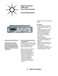
Introduction
Congratulations on choosing your new TM I OOOE Multipurpose Lightweight Rail Drill. The drill is a quality
product with unique features that make this the perfect solution for your entire rail drilling requirements.
•
Easy to use and rugged design makes the TMI OOOE a cost effective solution to drilling clean, accurately
positioned holes in rail sections for bonds, and fishplates.
•
Powered by a 11 OV motor with a speed of 430 rpm freespeed.
•
Can drill up to 36mm with annular broaching cutters.
•
The new integral arbor support gives guaranteed hole tolerance and ensures no burring of hole.
•
The totally enclosed cutter action ensures operator safety.
•
The new and unique Tommy bar clamping system facilitates clamping in confined spaces such as check
rail.
•
The hard wearing and tough metal carry case provides protection for your drill in transit. The spacious
design leaves enough room for all of your too Is and ancilliaries.
2.0
Getting To Know Your TMlOOOE
Before you use your new TMlOOOE please take the time to familiarize yourself with the functions and controls.
3.0
TMlOOOE Ancillary Components/Equipment
3.1
The Coolant Bottle
The Pressurized Coolant System designed to give maximum coolant and lubrication will help to prolong cutter
life. As well as ensuring a clean hole every time.
NB. Always use recommended cutting fluid.
3.2
Storage Case
This hard wearing and tough metal carry case provides protection for your drill in transit. The spacious design
leaves enough room for all of your tools and ancilliaries.
3.3
Index Drilling Plate
Used to ensure holes are correctly distanced from end of rail and centre to centre, guaranteed to provide
complete accuracy.
3.4
Rail Shoes
Manufacturing from hardened tool steel, ensuring accuracy and repeatability.
3.5
Broaching Cutters
Universal broaching cutters provide an unrivaled quality and accuracy allowing you to drill with confidence.
3.6
Chuck Adapter
This Chuck adapter can be used to fit any standard stub drill to the TMlOOOE giving you the ability to cut any
hole upto a maximum diameter of 13mm.
4.0
Operating Instructions
4.1
Fitting A Broaching Cutter
4.1.1
To fit a Broaching Cutter
•
•
•
•
•
•
Disconnect machine from power supply.
Insert the pilot pin in the broaching cutter. The main
function of the pilot pin is to ensure ejection of the slug at
the end of each drilling cycle.
Loosen the grub screws so the shank of the cutter fits
neatly into the arbor.
Align the flats of the cutter with the grubscrews.
Insert the cutter firmly into the arbor compressing the
internal spring until the shoulder of the cutter meets the
end of the arbor and tighten the grub screws.
Always have damaged grub screws replaced.
4.1.2
•
•
•
•
4.1.3
•
•
•
To Remove a Broaching Cutter
Loosen the grub screws.
The cutter will move out of the arbor under spring
pressure.
Remove the cutter from the arbor
NB it is advisable to store the drill with the grub screws wound in.
Problems
The cutter will not insert into the arbor.
Check that the grub screws are wound out and the arbor is
free from debris.
Always make sure the screws clamp onto the flats. Failure
to do so could result in the screws standing proud of the
arbor and therefore causing damage to the guide bush.
4.2
Using the Chuck Adapter
4.2.1
Fitting the Chuck Adapter
•
The chuck adapter is fitted in exactly the same way as a
broaching cutter. (See section 4.1)
4.2.2 Using a Twist Drill in the Chuck Adapter
•
•
Insert the drill in the chuck.
Tighten the chuck first by hand then using the chuck key
provided.
4.3
Fitting Rail Shoes
4.3.1
To Fit Rail Shoes
•
•
•
Ensure the ejector grub screw is wound back into the base plate.
Push the shoe firmly onto the locating pins.
Insert the 2 hex cap bolts and tighten.
4.3.2
•
•
Removing Rail Shoes
Loosen and remove the two hex cap bolts.
Remove the rail shoe.
Note: If the shoe is tight use the ejector grub screw to force the rail shoe off.
4.4
Coolant System
4.4.1
Filling the pressurized sprayer bottle
•
•
•
Remove the pump mechanism by turning the handle anticlockwise.
Fill with recommended lubricant.
Replace the pump mechanism and fasten clockwise
4.4.2
•
•
•
4.4.3
•
•
Removing the lubricant from the drill
Turn the valve on the pipe to 'OFF' to stop the coolant flow.
Remove the pipe by pressing the release ring on the coolant adapter.
4.4.5
•
•
Attaching the Lubricant to the drill
Push the pipe from the bottle into the coolant adapter.
Turn the valve on the pipe to the 'ON' position to start coolant flow.
4.4.4
•
•
Preparing the bottle for use
Ensure the bottle has sufficient lubricant.
Pump the handle 4 to 5 times or until resistance is met.
Depress the handle and turn clockwise to lock.
Depressurizing the coolant bottle
Tum the pressure release valve anticlockwise to release the pressure.
Close the valve by turning it clockwise.
4.5 Using the Indexing Plate
•
The machine is normally used with hole positioning indexing plates for 113FB, 95LB, U69 and ALU rail
•
Fit to rail head.
•
Make sure the end stop is to end of rail.
•
Tighten locking screw.
•
Locate the Clevis arm into the index slot, and clamp the Rail Drill as described in section 4.6.1.
•
Drill the first hole
•
Un-clamp the Rail Drill as described in section 4.6.2
•
Clean between the rail shoes with a hand brush to clear all swarf
•
Repeat above procedure for drilling the second hole.
4.6
Using the Over Rail Clamp
4.6.1
Attaching the Drill
•
•
•
•
•
•
Before attaching the rail drill ensure that the rail surface is free
from debris and swarffrom previously drilled holes.
Place the rail drill over the rail section and locate the clevis arm
into the first slot of the indexing plate (If used).
Locate the rail shoes correctly in the web of the rail.
Pull the tommy bar shaft away from the drill unit, tum and locate
the end into it's pocket on the locking block.
Secure the drill by rotating the tommy bar shaft clockwise,
drawing machine firmly onto the rail.
Ensure that the rail shoes fit squarely into the rail web.
4.6.2
•
Removing the Drill
Once a hole has been drilled, release the rail drill by turning the
tommy bar shaft anti-clockwise until it is possible to pull the end
of the shaft out of the locking block pocket.
•
Fold the tommy bar shaft back against the rail drill base plate and
lift the drill clear of the rail or indexing strip. (If used)
•
Clear swarf
After every hole is drilled, always make sure that the Nylube Bush is
clean from any swarf, as it may cause the bush to wear. If the Arbor
starts to wobble the Nylube Bush is ready for replacing.
•
Repeat from 4.6.1 for second hole using second slot on indexing
plate. (If used)
4. 7
Drilling a Hole
•
Having fitted the indexing plate (see section 4.5) and clamped the machine to the rail.
•
Ensure the correct power supply (I IOV) is connected.
•
Switch on mains indicated by red neon.
•
Ensure the cutter is clear of rail web
•
Switch on coolant supply and check that no swarf is restricting the arbor movement through the nylube
bush.
•
Switch on the motor.
•
Apply a small amount of drilling pressure until the cutter is engaged in rail web.
•
Increase pressure making sure not to overload the motor.
•
Check the slug has been ejected at the end of each drilling cycle.
•
Retract the cutter making sure the cutter is again clear of rail web.
•
Tum off the motor and coolant supply.
4.8
Storing and Packing the TMlOOOE
4.8.1 To Pack the TMlOOOE Rail Drill
•
Place the drill into the case
•
Put any cutters rail shoes etc into the bottom of the case.
•
Place the indexing strips across the top of the drill.
•
Finally put the Pressure bottle across the top.
5.0
Do's and Don'ts.
•
Do not attempt to connect the machine to any power supply other than IlOV AC single phase.
•
Do not change a cutter with the machine connected to it's power supply.
•
Do make sure that you have the correct rail shoes fitted for the rail section to be drilled and are using the
correct hole positioning indexing plate.
•
Do make sure you have installed the correct size cutter for the rail section to be drilled.
•
Do make sure the cutter fitted is sharp without any of its cutting edges damaged.
•
Do not use unnecessary pressure to force the cutter through the rail. This may damage both the machine and
the rail. It may also result in personal injury.
•
Do always use coolant when drilling holes.
•
Do not allow other persons into the area in which you are operating the machine.
•
Do remember the slug which is ejected at the end of the drilling process can cause injury. Keep the area
clear at all times.
•
Do always wear the correct P.P.E. when operating the machine, including safety glasses/goggles.
6.0 Maintenance
6.1
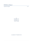
Parts List for Main Body
6.2
Parts Diagram for Main Body
Clamp Assembly Diagram & Parts List
6.3
6.4
65
6,6
6. 7
6,8
Motor Unit Diagram
Motor Unit Part List
Wiring Diagram
Slide Adjustment
Nylube Bush
6.1 Parts List for Main Body
...
ITEM No.
1
2
3
4
5
6
7
8
9
10
11
12
13
14
15
16
17
18
19
20
21
22
23
24
25
QTY
1
2
1
1
1
1
2
1
3
3
1
2
1
1
1
1
1
1
1
1
1
1
2
26
1
27
28
29
30
31
32
33
34
1
1
1
1
1
1
1
1
PART No.
DESCRIPTION
Minibor Bo<;ly_J1332 Yellow)
6o100A MiniborBr9ss Strip(AnQied)
20389
Minibor G.F .s.
10215
Minipor Rack
10084Z
Top Pl~te (Zinc)
M0042Z
Pinion"M~gtron (Large)
;
'M0081
Pinion Bush
Pinion End Cap (Deep) Zinc
M0072Z
Handle 12mm Small Zinc
10081.2
HaridJe Knob t2mm Knock on
1.0082
2014$
Uni2 Cradle
U.ni 2 Side Bracket (Zinc)
103622
61B01R U.ni 2 DrUI110v Eibenstoc.k Rail
RAIL PLATE ffM1 OOOE SWitch Plate
10090
Insulator Box (Unibor)
PCB(LY2110v)
60004
20307 .·.Magnet Switch 1/4 Neon
20311
Actu~tor
Switch·
. .
. . . cl.Jl1iversal)
Switch
Protector
(Universal}
20361
...
.. ...
..
...
F.t;~s¢ Holder
20317
ARBOIL5 Arbor 1"M1 000 Electric MT2
Arbor Spring
SPR101
Arbor Ejection PJyg
10205A
RT019
TM1 000 Art:>or Coolant Rinq
RTB003 [M1000.Arbor Coo!<mt .Seal
RTB002 [ij1000 Arbor CoolaritCirClip
R.T020
[J:M1 000 Arbor Coo1~nt Wi:l$her
50037C
118'' BSP ..:6mm 90 OeQ Push Fitting
50015F
1/4" BSP- 6mm Slraiqht Push Fitting
CBV004 BaH tap 114" BSP Male/Female
CBA006 Adapter 1/4" BSP - 18mm
50013C
6mm Oil Coolant Pipe (LonQ)
RT313
rrM1 000 Coolant Pipe Clip
10060Z
[M1 000 Oilfeed Bracket
20348~Y
-
-
-
-
,,
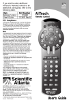
6.2 Parts Diagram for Main Body
Additional Rail Shoes and Index Plates
RAIL SHOES
RTS-FB
RTS-BH
RTS-15DLB
RTs~coN
INDEX
STRIP
RfS:-FS
RTS;;U69
6.4
ITEM
NUMBER
RT021
RT073
Rf068
RT075
j.
l
TM1000 113LB FLAT BOTTOM
TM1000 95LB BULL HEAD
TM1000 150LB
'rM1000 AL\SS CONDUCTOR
DESCRIPTION
ITEM
NUMBER
RT057
TM1000 113LB FLAi BOTTOM
RT06()
fMtdOO
RT(J53
RT062
MQtor Unit Diagram
Ii
DESCRIPTION
95LB BULL HEAD
TM1000 U69
TM1000 AL\SS CONDUCTOR
6.5 Motor Unit Parts List
Number
'
Item Nmriber
'
1
802Q1284
74322240
80201196
<
'
Description
"/
'
.,_
'-
. SELF TAP-PING SCREW
· CAP. iNCL. P-G9
BRUSH HOLDER COMPLETE
·Blrusa
4
.6
8.0201180
80201385
7
··1122~oo·
8020l266:
SCREW
STATOR COMPLETE
• SELF TAPPING SCREW
. 7132'3140
12
13
80410011
802013333
14·
8.0410011
15
··sozot~zo
742Z2lOO
17
18
19
20
21
22
GROOVED BALL BEARING.
LOCKING lUNG
ROTOR COMPLETE
71321430
80200502
QE.OQ\ml) BALL BEARING
713i3420
WORK SPINDLE
71323400
• SELFTAP:PINGSCREW
24
25
. 80410010
71323470
26
ENf;> SHlELD OF GEARING
27
29
80200601
. 30
$IIA.f'f WIT}{ CLUST~R QBARS
80200602
33
34
71323460
36
71323:520
8o2tl1296
37
jg
40
FIITING SPRING
GEAR SWITCH~ COMPLETE
CDUPLING BOLT.: COMPLETE
86Soooto
8060Pi64
80201284
PLASTIC CLIP
SELF TAPPING S:C:REW
!
35
36
37
38
39
40
41
42
43
44
45
46
47
48
49
50
1
1
1
2
1
1
2
1
8
2
2
4
6
4
5
6
VVarnirug Plate
RM239
10231
M16 Strain Relief Cable Gland
10237-1
110v Yellow Cable
40026
M16 Push Fit Gland
M0443
Conduit
CLA002
Clamp Assembly
SC88GRUB M8 x 8 Grub Screw
SC630CAP M6x 30 Cap Screw
SC620CAP M6 x 20 Cap Screw
SC616BUT M6 x 16 Button Head Screw
SC616CAP M6 x 16 Cap Screw
SC612CAP M6 x 12 Cap Screw
SC525GRUB M5 x 25 Grub Screw
SC516CAP IM5 x 16 Cap Screw
SC510BUT IM5 x 10 Button Head Screw
NUT-M5 [Ms Nyloc Nut
Additional Parts List (Complete assembly 70)
Dia No
.70A
70B
70C
700
71
Stock-No
RT053AZ
RT053BZ
RT053CZ
RT053DZ
RT088Z
''"''"'""-•········
Description
U69 SMALL BASE
U69 LARGE BASE
U69 CLAMP
DOWEL
U69 TOMMY BAR
Qty
1
1
1
4
'1
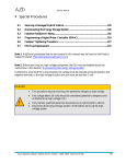
6.3 Exploded view of Clamp Assembly CLA002
Item No.
1
2
3
4
5
6
7
8
9
10
11
12
13
14
15
16
17
18
Part No.
Description
Rt305
Rt302
Rt135
Rt026
Rt017Z
Rt134
10082
20346
Rt048
Rt016
Rt015
Rt011
SC620cap
SC516cap
SC830cap
DWL-830
SC810grub
As specified
TM1000 Electric Base plate
Screw clamp locking shoe
Screw clamp pivot shaft
TM1000 locking arm
Cam pin end cap
Screw clamp locking shaft
12mmknob
012 handle
Locking artn clevis
Cam pivot pin
TM1000 leg release spring
TM1 000 Nylube bush
M6x20 capscrew
-M5x16 capscrew
M8x30 capscrew
08x30 Lg Dowel
M8x10 Grubscrew
Rail shoe
Qty
1
1
1
2
4
1
2
1
1
1
1
1
2
7
8
6
2
2
(~) ~)(~
'
•\
i
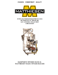
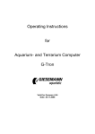
6.6 Wiring Diagram.
~TARi\STCiP
j
j
RELAY
....
J
'-----
=~;-.
"C.B.
Fl!St
W.AG~ET
SR[
!_ ..:{::
:~=~:=~~:t:
DOU!iLE POLE
[ BR
L_J_____ . L
ON\0P'F SWiTCH
6.3
M~.
FUSE
6. 7 Slide Adjustment.
•
•
•
•
After repeated use the cradle may become loose and need to be
tightened.
Put 2.5mm Allen Key into head of cradle retaining nuts, using
8mm Spanner undo the locking nuts anti-clockwise holding the
Allen key without moving grub screws.
Using the Allen Key gently tighten screws in series until the
cradle moves freely in the slide but does not allow the motor to
wobble.
When adjustment is complete re-tighten locking nuts
clockwise.
6.8 Nylube Bush.
•
(Rf~Jf'.!DANTJ
[DJOT?J
~
I cp I tn l
After every hole is drilled, always make sure that the Nylube
Bush is clean from any swarf, as it may cause the bush to wear.
lfthe Arbor starts to wobble the Nylube Bush is ready for
replacing.
l'
_\