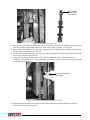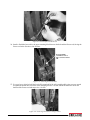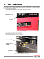
1
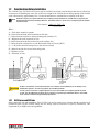
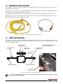
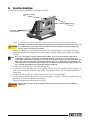
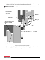
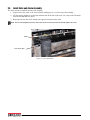
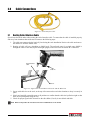
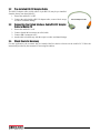
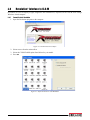
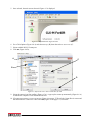
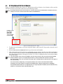
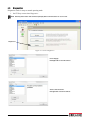
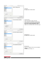
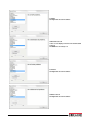
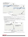
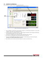
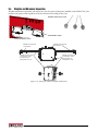
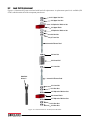
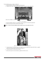
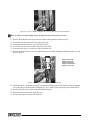
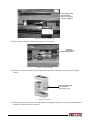
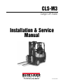
CLS-M3 Cargo Lift Scale Installation & Service Manual 157393 Rev B Contents 1.0 About This Manual ....................................................................................................................... 1 Introduction.................................................................................................................................. 1 1.1 Safety . . . . . . . . . . . . . . . . . . . . . . . . . . . . . . . . . . . . . . . . . . . . . . . . . . . . . . . . . . . . . . . . . . . . . . . . 1 1.2 Considerations Before Installation . . . . . . . . . . . . . . . . . . . . . . . . . . . . . . . . . . . . . . . . . . . . . . . . . 2 1.2.1 CLS Classes and ID Plates . . . . . . . . . . . . . . . . . . . . . . . . . . . . . . . . . . . . . . . . . . . . . . . . . . . . . . . . . . 2 1.3 CLS-M3 Power and PC Connection . . . . . . . . . . . . . . . . . . . . . . . . . . . . . . . . . . . . . . . . . . . . . . . . 3 1.4 iQube2 J-Box Introduction . . . . . . . . . . . . . . . . . . . . . . . . . . . . . . . . . . . . . . . . . . . . . . . . . . . . . . . 3 2.0 Scale Base Installation................................................................................................................ 4 2.1 Before Installation . . . . . . . . . . . . . . . . . . . . . . . . . . . . . . . . . . . . . . . . . . . . . . . . . . . . . . . . . . . . . . 4 2.2 Tools Needed to Install the CLS-M Onto the Forklift. . . . . . . . . . . . . . . . . . . . . . . . . . . . . . . . . . . 4 2.3 Unpacking . . . . . . . . . . . . . . . . . . . . . . . . . . . . . . . . . . . . . . . . . . . . . . . . . . . . . . . . . . . . . . . . . . . . 5 2.3.1 2.3.2 Unpacking A One Scale Configuration . . . . . . . . . . . . . . . . . . . . . . . . . . . . . . . . . . . . . . . . . . . . . . . . . 5 Unpacking A Two Scale Configuration . . . . . . . . . . . . . . . . . . . . . . . . . . . . . . . . . . . . . . . . . . . . . . . . . 7 2.4 Scale Base Installation . . . . . . . . . . . . . . . . . . . . . . . . . . . . . . . . . . . . . . . . . . . . . . . . . . . . . . . . . . 9 2.5 Connect the Coiled Interface Cable to J-box . . . . . . . . . . . . . . . . . . . . . . . . . . . . . . . . . . . . . . . 11 2.6 Install Forks onto Scale Assembly . . . . . . . . . . . . . . . . . . . . . . . . . . . . . . . . . . . . . . . . . . . . . . . . 12 3.0 Cable Connections ..................................................................................................................... 13 3.1 3.2 3.3 3.4 4.0 Routing Coiled Interface Cable. . . . . . . . . . . . . . . . . . . . . . . . . . . . . . . . . . . . . . . . . . . . . . . . . . . Pre-installed RS-232 Adapter Cable . . . . . . . . . . . . . . . . . . . . . . . . . . . . . . . . . . . . . . . . . . . . . . Connecting the Coiled Interface Cable/RS-232 Adapter Cable to Mobile PC . . . . . . . . . . . . . . Check Scale for Accuracy. . . . . . . . . . . . . . . . . . . . . . . . . . . . . . . . . . . . . . . . . . . . . . . . . . . . . . . 13 14 14 14 Revolution® Interface to CLS-M ............................................................................................... 15 4.0.1 Connect Scale to Revolution . . . . . . . . . . . . . . . . . . . . . . . . . . . . . . . . . . . . . . . . . . . . . . . . . . . . . . . . 15 4.1 Live Weight Data . . . . . . . . . . . . . . . . . . . . . . . . . . . . . . . . . . . . . . . . . . . . . . . . . . . . . . . . . . . . . . 17 4.2 Leveling Forklift Forks . . . . . . . . . . . . . . . . . . . . . . . . . . . . . . . . . . . . . . . . . . . . . . . . . . . . . . . . . . 18 4.3 Calibration . . . . . . . . . . . . . . . . . . . . . . . . . . . . . . . . . . . . . . . . . . . . . . . . . . . . . . . . . . . . . . . . . . . 20 4.3.1 Reading Data In Live Weight Screen . . . . . . . . . . . . . . . . . . . . . . . . . . . . . . . . . . . . . . . . . . . . . . . . . . 23 4.4 EZ Setup/Upload Unit Serial Number. . . . . . . . . . . . . . . . . . . . . . . . . . . . . . . . . . . . . . . . . . . . . . 24 4.5 Diagnostics . . . . . . . . . . . . . . . . . . . . . . . . . . . . . . . . . . . . . . . . . . . . . . . . . . . . . . . . . . . . . . . . . . 25 5.0 Calibration ................................................................................................................................. 28 5.1 Leveling Forklift Forks . . . . . . . . . . . . . . . . . . . . . . . . . . . . . . . . . . . . . . . . . . . . . . . . . . . . . . . . . . 28 5.2 Carriage J-Box Calibration Mode . . . . . . . . . . . . . . . . . . . . . . . . . . . . . . . . . . . . . . . . . . . . . . . . . 29 5.3 Calibrate Scale Using Revolution . . . . . . . . . . . . . . . . . . . . . . . . . . . . . . . . . . . . . . . . . . . . . . . . . 30 5.3.1 Reading Data In Live Weight Screen . . . . . . . . . . . . . . . . . . . . . . . . . . . . . . . . . . . . . . . . . . . . . . . . . . 33 5.4 Weights and Measures Inspection . . . . . . . . . . . . . . . . . . . . . . . . . . . . . . . . . . . . . . . . . . . . . . . . 34 6.0 Load Cell Replacement.............................................................................................................. 35 6.1 Required Tools for Replacing a Load Cell . . . . . . . . . . . . . . . . . . . . . . . . . . . . . . . . . . . . . . . . . . 35 6.2 Load Cell Replacement . . . . . . . . . . . . . . . . . . . . . . . . . . . . . . . . . . . . . . . . . . . . . . . . . . . . . . . . . 36 7.0 iQube2 J-Box Replacement ....................................................................................................... 43 7.1 Download the Serial Number to the J-Box . . . . . . . . . . . . . . . . . . . . . . . . . . . . . . . . . . . . . . . . . 44 8.0 Appendix .................................................................................................................................... 45 8.1 Parts Breakout. . . . . . . . . . . . . . . . . . . . . . . . . . . . . . . . . . . . . . . . . . . . . . . . . . . . . . . . . . . . . . . . 45 8.2 Troubleshooting Table . . . . . . . . . . . . . . . . . . . . . . . . . . . . . . . . . . . . . . . . . . . . . . . . . . . . . . . . . 48 Technical training seminars are available through Rice Lake Weighing Systems. Course descriptions and dates can be viewed at www.ricelake.com/training or obtained by calling 715-234-9171 and asking for the training department. © Rice Lake Weighing Systems. All rights reserved. Printed in the United States of America. Specifications subject to change without notice. Rice Lake Weighing Systems is an ISO Registered Company. November 27, 2013 i CLS-M2 Installation Manual Rice Lake continually offers web-based video training on a growing selection of product-related topics at no cost. Visit www.ricelake.com/webinars. ii About This Manual This manual is for trained and qualified personnel responsible for installing and servicing the CLS-M Cargo Lift Scale. This manual covers information on the installation and service of the scale carriage, coiled interface cable to the mobile PC. 1.0 Introduction The CLS-M3 Cargo Lift Scale is a rugged, dependable cargo lift scale that can withstand many years of repeated use. When mounted on a forklift, the CLS-M3 saves time and money by allowing you to weigh loads immediately instead of carrying the load to a floor scale. 1.1 Safety Safety Signals Safety Symbol Definitions: DANGER Indicates an imminently hazardous situation that, if not avoided, will result in death or serious injury. Indicates a potentially hazardous situation that, if not avoided could result in death or serious injury, and WARNING includes hazards that are exposed when guards are removed. CAUTION Indicates a potentially hazardous situation that, if not avoided may result in minor or moderate injury. Indicates information about procedures that, if not observed, could result in damage to equipment or Important corruption to and loss of data. General Safety Do not operate or work on this equipment unless you have read and understand the instructions and warnings in the Installation, Operation and Maintenance Manual. Failure to follow the instructions or heed the warnings could result in injury or death. Contact any Rice Lake Weighing System dealer for replacement manuals. Proper care is your responsibility. WARNING Failure to heed may result in serious injury of death. Some procedures described in this manual require work inside the j-box. These procedures are to be performed by qualified service personnel only. Take all necessary safety precautions when installing the scale carriage including wearing safety shoes, protective eye wear, and using the proper tools. DO NOT allow minors (children) or inexperienced persons to operate this unit. DO NOT operate without all shields and guards in place. DO NOT jump up and down on the scale. DO NOT use for purposes other then weight taking. DO NOT place fingers into slots or possible pinch points. DO NOT use any load bearing component that is worn beyond 5% of the original dimension. DO NOT use this product if any of the components are cracked. DO NOT exceed the rated load limit of the unit. DO NOT make alterations or modifications to the unit. DO NOT remove or obscure warning labels. DO NOT use near water. Keep hands, feet and loose clothing away from moving parts. 1 CLS-M2 Installation Manual 1.2 Considerations Before Installation The CLS-M Cargo Lift Scale will fit most typical forklifts, but certain considerations that must be taken into account prior to installing the scale. Due to the extra weight of the CLS-M, the net lifting capacity of the forklift scale is decreased by approximately 10%. Use the formula below to calculate the net capacity of the unit. Formulas can give you a good estimate of how capacity will be affected. You should work closely with your Note forklift manufacturer before making a decision. Their data reflects, in most cases, testing with specific forklifts and attachments. Net Capacity = A(B + C) - D (E + F) E+G+H Where: A = Truck basic capacity in pounds B = Inches from the front wheel center line to fork face C = Inches from the fork face to the truck rating point (usually 24") D = Weight of the scale in pounds (419 lb) E = Inches from the front wheel center line to the carriage face F = Inches from the carriage face to scale Horizontal Center of Gravity (HCG) G = J + K (inches from the carriage face to the rear fact of load) H = Inches from fork face to new truck rating point J = Thickness of fork K = Thickness of scale Another consideration is the indicator power source will be connected directly to the battery of the CAUTION forklift. Most typical is 12 volts for propane, gas and diesel forklifts. 12 volt systems must have a negative ground so ensure the forklift has a negative ground electrical system. The CLS-M Cargo Lift Scale will not operate on a positive ground forklift. Refer to the forklift users manual to further verify grounding requirements. 1.2.1 CLS Classes and ID Plates During the initial sale and installation of the CLS-M, you need to remind your customer that they must have an updated ID plate on their forklift stating the new lifting capacity and center of gravity information. This requirement is per OSHA rules and regulations. Introduction 2 1.3 CLS-M3 Power and PC Connection The CLS-M3 recieves power from a mobile PC through the RS-232 port, this eliminates the need for a Commmunication/Power box. The iQube2 j-box interfaces to Virtui2 software that has been pre installed on the mobile PCs operating system. It allows the operator to display weight and zero the scale. To calibrate and troubleshoot the CLS-M3, Revolution– software has been installed on the mobile PC as well. The mobile PC receives data and power (5V on pin 9) from the iQube2 j-box through the Coiled Interface Cable, PN 156295 and RS-232 adapter cable (PN 156296). RS-232 Adapter Cable Figure 1-1. Coiled Interface Cable and Adapter 1.4 iQube2 J-Box Introduction The iQube2 j-box sits in an area between the front and back plate of the scale itself providing protection for the j-box. It comes from the factory pre-wired and no additional work needs to be done to it other than sealing it for Legal for Trade applications. Coiled interface cable connection Load cell cable PN 125559 For j-box parts breakdown see Section 8.0, Figure 8-3. Calibration switch cover Load cell cable PN 125559 W & M seal location W & M seal location W & M seal location Location of the two-channel j-box Figure 1-2. Two-Channel J-Box on CLS-M Scale After successful installation (Section 2.0) and calibration (Section 5.0), replace the cover on the scale assembly Note and secure with bolt and washer. 3 CLS-M2 Installation Manual 2.0 Scale Base Installation This section describes procedures for installing the CLS-M scale base. Take all necessary safety precautions when installing the scale carriage, including wearing safety shoes WARNING and protective eyewear, and using the proper tools which are listed in Section 2.4. The CLS-M Cargo Lift Scale is shipped from the factory with the scale already calibrated and all settings stored in the j-box. Minimal adjustments and calibration might be necessary once the scale is installed onto the forklift. Those calibration steps are contained in Section 4.0. 2.1 Before Installation Before installing the CLS-M on a forklift, the forklift should be in good operating condition in order to get the optimal amount of weighing accuracy. The following items are things to look for prior to installing the CLS-M onto a forklift: • Inspect the forks for any damage. • Check the locking pin on the forks for proper function. • Check and adjust the lift chain so the heel of the forks have 1/2" to 1" of clearance from the floor when the carriage is down and the mast is vertical. • The slot for the center pin should be clear of grease and debris. • The top cleats of the forklift rest on the top of the scale and should remain clear of grease and debris that could alter the scales’ performance. The CLS-M scale works with 9-36 VDC power source. CAUTION All systems must have a negative ground. 2.2 Tools Needed to Install the CLS-M Onto the Forklift Once the forklift is deemed in good mechanical and operating condition, you’ll need the following tools to remove it from its shipping pallet and install onto the forklift. Tool Size Allen wrench Cresent wrench Tin snips or band cutters Torque wrench w/ 1/2" Allen Electric grinder Level 4mm 2" adjustable 1/2" NA Purpose of Tool For service only, to remove j-box For adjusting the shim bolts and jam nuts. To cut the plastic banding surrounding the CLS while on the pallet. To tighten the cleats to 125 ft-lb. For grinding the center pin if necessary and the mounting bolts. To perform angle zero calibration. Table 2-1. Recommended Tools for Unpacking and Installation of the CLS-M Scale Base Installation 4 2.3 Unpacking The CLS-M Cargo Lift Scale is shipped upright on a sealed pallet with one or two scales per pallet, as shown in Figure 2-1. Hardware component boxes Figure 2-1. CLS-M Packaging Upon receipt of the shipping pallet, inspect it for any visible signs of damage. Immediately after unpacking, visually inspect the contents to ensure all components are included and undamaged. The shipping pallet should contain the following: • One or two scale carriage assemblies with cover plate • Hardware component boxes which include: • Two cleats with four bolts • One coiled interface cable • Coiled cable rear mounting bracket • Coiled cable to RS-232 adapter cable To ensure that all products received from the manufacturer are in good shape upon arrival, it is recommended Note to fully inspect all contents and properly fill out the bill of lading. If any parts were damaged in shipment, notify the shipper immediately. 2.3.1 Unpacking A One Scale Configuration The scale is shipped in an upright position as illustrated in Figure 2-2. The upright position allows for ease of installation. The accessories are located in a hardware component box. 1. Clip plastic band holding hardware component box in place and remove box. 2. Remove protective wood piece from the front of the scale. 3. Remove the front pallet support. 4. Clip the remaining plastic bands that are encircling the scale. 5. Remove the protective wood piece which protects the front of the scale. 5 CLS-M2 Installation Manual Scale Hardware component box Protective wood covering Wood shipping pallet Front pallet support Exploded view of components Hardware component box plastic banding Front pallet support Protective wood covering Step 1: Clip plastic band securing hardware component box Step 2: Remove protective wood covering Step 3: Remove front pallet support Plastic banding securing scale to pallet Protective wood covering Step 4: Clip remaining plastic bands Step 5: Remove protective wood Scale is now ready for installation Figure 2-2. Scale Component Parts on Shipping Pallet for One Scale Scale Base Installation 6 2.3.2 Unpacking A Two Scale Configuration The scales are shipped in an upright position as illustrated in Figure 2-3. The upright position allows for ease of installation. The accessories are located in a hardware component box. When installing from a two scale configuration, complete all of steps for scale one before clipping plastic WARNING bands securing second scale to the shipping pallet. 1. Clip top plastic bands. 2. Clip plastic band securing cardboard boxes to shipping pallet. 3. Remove the cardboard boxes. 4. Clip plastic bands from scale one. 5. Remove protective wood covering for scale one. Scale one is ready for installation. 6. Once scale one has been installed, clip plastic bands from scale two. 7. Remove protective wood covering for scale two. Scale two is now ready for installation. 7 CLS-M2 Installation Manual Scale Hardware component boxes Protective wood covering Protective wood covering Wood shipping pallet Exploded view of components Plastic banding Plastic banding Protective wood covering Step 1: Clip top plastic bands Step 2: Clip plastic band to release hardware component boxes Step 3: Remove hardware component boxes Step 4: Clip plastic bands from first scale Step 5: Remove protective wood covering for first scale Scale one is ready for installation. DO NOT clip the plastic band from scale two until scale one is installed Step 6: Clip plastic bands from scale two. Step 7: Remove protective wood covering for second scale. Scale two is ready for installation. Figure 2-3. Scale Component Parts on Shipping Pallet for Two Scales Scale Base Installation 8 2.4 Scale Base Installation Use the following steps to install the scale base to the forklift. Anti-shift centering pin Top cleat location Shim bolt hole location(s) Figure 2-4. Anti-shift Centering Pin, Shim Bolts and Top Cleat Locations (One Scale Configuration Shown) Verify that the shim bolts are flush with the back plate of the scale. Not doing so will place the entire scale CAUTION out of alignment when attaching it onto the forklift and will make it difficult to make final adjustments once the scale is mounted onto the forklift. 1. Making sure the forks are removed from the forklift, move the forklift in close to the pallet and scale. 2. Ensure the anti-shift centering pin on the scale assembly is aligned with the center notch on the forklift carriage. The scale’s centering pin should be aligned with the middle notch of the forklift carriage. Verify that the Note centering pin is adjusted so that the pin is located well within the center notch area of the carriage. The centering pin should not touch the bottom of the notch on the original carriage, as this will cause side to side tilting of the scale. The outside top cleats provide support to the scale assembly and the centering pin only helps to position the scale on the forklift carriage. The centering pin should not bear any weight. If it does, the use of a grinder to grind down the centering pin will help remedy that. 3. Tilt the mast forward slightly to catch the scale assembly. 4. Carefully and slowly raise the scale carriage slightly so the top cleats (cleat location shown in Figure 2-4) of the scale hook onto the forklift carriage. If they do not hook, push the scale toward the forklift as it is being raised. 5. Tilt the mast back to secure the connection and raise the scale to shoulder height. 6. Attach the bottom cleats to the bottom of the scale assembly (see Figure 2-5 for bottom cleat location), so that the lip of the cleat is behind the scale carriage. 7. Torque the bottom cleat retaining bolts to 125 ft-lb. Failure to properly torque the bottom plate retaining bolts may result in bodily harm or damage to WARNING equipment. 9 CLS-M2 Installation Manual 8. Adjust the shim bolts so there is a minimal clearance between the bottom cleats and the scale carriage of .020 inch thickness. This can be measured by using the included feeler gauge. Failure to adjust shim bolts to proper clearance of .020 may result in binding, poor accuracy or improper fit of Note attachment to forklift. Illustration shown is with part of the flexure removed to show shim bolt location. Shim bolts Forklift carriage Bottom cleat retaining bolts Insert a feeler gauge to measure a.020 inch thickness between bottom cleat and forklift Bottom cleat Scale carriage 3/16" gap max, for installation on forklift to prevent side Figure 2-5. Bottom Cleat Location and Assembly 9. Upon successful installation and calibration verification, seal the carriage j-box and load cell quick disconnects for Weights and Measurements approval. Scale Base Installation 10 2.5 Connect the Coiled Interface Cable to J-box Assemble loop clamp kit onto coiled interface cable Loop Clamp Assembly PN 150720 Bolt Washer Loop clamp kit Scale cover assembly Push cable through hole in scale from back to front Assembled view Connect cable to j-box Figure 2-6. Connecting The Coiled Cable 1. 2. 3. 4. Loosen the bolt holding the cover to the scale assembly and remove cover. See Figure 2-6. Assemble loop clamp kit to the coiled interface cable. Push the coiled interface cable through the hole in the scale and connect it to the j-box. See Figure 2-6. Route the coiled cable through clips on backside of carriage toward middle for proper coiled cable routing, tighten clips. 5. Position the scale cover assembly and the loop clamp assembly to the scale and secure with the bolt and washer. After successful installation (Section 2.0) and calibration (Section 5.0), replace the cover on the scale assembly Note and secure with bolt and washer. 11 CLS-M2 Installation Manual 2.6 Install Forks onto Scale Assembly The forks need to be installed onto the scale assembly. 1. Align a fork to the center of the scale assembly making sure it is over the top of the assembly. 2. Lift the carriage slightly to set the fork and then slide to the side of the scale. Let it stop in the 2nd notch from the end and latch it in place. 3. Repeat process for other fork, sliding it the opposite direction on the scale. Note For accurate weighing it is best to leave forks at the second notch from the outside edge of the scale. Fork Last notch open Figure 2-7. Fork Attachment Scale Base Installation 12 3.0 Cable Connections Figure 3-1. Coiled Interface Cable 3.1 Routing Coiled Interface Cable Special care should be taken when routing the coiled interface cable. To ensure that the cable is installed properly and away from situations that could cause it harm use the following steps: 1. The cable was connected to the load cell j-box during the scale installation. Retrieve the cable and route to the mobile PC from the forklift scale. 2. Routing of cable will vary depending on forklift style. The preferred route for a single stage forklift is through the center of the mast, up the front/right upright, to the area where the mobile PC is mounted. Coiled interface cable Cable tie Cable tie Figure 3-2. Signal Cable Located Between the Scale and the Mobile PC 3. Secure with cable ties at the scale, at the top of the mast and several other locations to keep it securely in place. 4. Slowly and carefully extend the mast to all positions to confirm that the cable isn’t pulled too tight or that there are no pinch points along the way. 5. Check for proper signal cable clearance as the side shifter (if used), is moved back and forth. Note When routing cables do not obstruct the view of OSHA labels on the forklift. 13 CLS-M2 Installation Manual 3.2 Pre-installed RS-232 Adapter Cable The RS-232 adapter cable (coiled cable to 9-pin RS-232) may be pre-installed from the factory onto the mobile PC. 1. Ensure the mobile PC is OFF 2. Connect the coiled cable to RS-232 adapter cable, secure with tie wraps to reduce accidental damage. 3.3 Connecting the Coiled Interface Cable/RS-232 Adapter Cable to Mobile PC 1. 2. 3. 4. 3.4 RS-232 Adapter Cable Ensure the mobile PC is off. Connect female M16 connector to coiled cable. Connect DB-9 connector to PC. Attach cable to forklift cage with the wraps to reduce accidental damage. Check Scale for Accuracy For this application, the customer has pre-installed the Revolution software on the mobile PC. Follow the instructions provided by the customer for accessing Revolution. Cable Connections 14 4.0 Revolution® Interface to CLS-M Revolution is a tool to display weight, diagnostics and calibration (if required) of the CLS-M Scale using a Windows® based computer. 4.0.1 Connect Scale to Revolution 1. Open the Revolution program on the computer. Figure 4-1. Revolution Screen at Open 2. Select File/New from the main toolbar. 3. Select the CLS-M Forklift option listed below for your model. 4. Press OK. Figure 4-2. Open Revolution to CLS-M Module 15 CLS-M2 Installation Manual 5. Once selected, the main screen shown in Figure 4-3 is displayed. Figure 4-3. Expanded Pitch Angle Selection 6. Go to Tools/Options (Figure 4-4 A) and select Settings (B), then choose the PC Comm Port (C). 7. Select available RS-232 Comm port. 8. Click OK ( Figure 4-4 D). A C B 1 D Figure 4-4. Options Screen to Select Comm Port for USB 9. Select the connect icon from toolbar ( Figure 4-5 A). A pop-up box comes up momentarily (Figure 4-6 A) to indicate the computer is now indicated to the box. 10. If it comes up as Unable to Connect to Indicator (Figure 4-6 on page 17 B) verify the Comm Port is correct and that the mobile PC is turned on. Then select GO (Figure 4-6 on page 17 C) to connect. Revolution® Interface to CLS-M 16 A B Figure 4-5. Connect Revolution C A B Figure 4-6. Connection Success/Failure 11. Press EZ Setup button (B). 4.1 Live Weight Data The second tab is the Live Weight Data screen. This screen is used during calibration of the scale to verify the weight values. The Live Weight Data screen will only operate with the calibration switch in the closed position. 1. Select the Live Weight Data tab (Figure 4-7). Weight data packet screen shows output format of CLS-M. Other displays include weight, pitch angle, roll Note angle, cell 1 & 2mV. (Figure 4-7). This is the information that will be sent to the customer supplied handheld device when attached through Bluetooth. To start streaming data check the auto refresh box. If not checked the refresh button will need to be selected after each change of weight to load cell. 17 CLS-M2 Installation Manual C D E A F B G H Figure 4-7. Revolution Live Weight Data screen. A. B. C. D. E. F. G. H. 4.2 Weight Data Packet - output format/displays the output protocol of the CLS-M. Auto Refresh - when checked it starts continuous streaming of data in the weight data packet. Zero - used to zero the scale. Weight - displays value of weight on scale. Pitch Angle - angle of the scale in a front to back direction. Roll Angle - angle of the scale in a side to side direction. Cell 1 mV (raw) Cell 2 mV (raw) Leveling Forklift Forks 1. Level the forks to 0° by placing a level on the forks and adjusting as required. Note Carriage j-box will need to be in setup mode (See Section 5.2) Turn off the forklift after leveling forks, high vibration from the running engine will cause inaccurate readings. 2. In the setup screen, press Zero Angle (Figure 4-8 A). 3. A pop-up appears as shown in (Figure 4-8 B), press OK to close the pop-up box. Revolution® Interface to CLS-M 18 A B Figure 4-8. Zero Forks Forks should be level when testing calibration. A degree of tilt in either direction can cause errors in the use of Note the scale. 19 CLS-M2 Installation Manual 4.3 Calibration Note The carriage j-box will need to be in setup mode (See Section 5.2) 1. Select Standard Calibration (Figure 4-9 B) 2. Press Next (Figure 4-9 C). B A C Figure 4-9. Enter Calibration 3. Enter test weight value to be used and press Next (Figure 4-10 A). “Certified Test Weight used during cell normalization” must be checked. Enter test weight value to be used, minimum suggested weight 500lbs. Certified Test Weight used during cell normalization” MUST be checked. A Future option, DO NOT use at this time. Figure 4-10. Enter Test Weight Value Revolution® Interface to CLS-M 20 4. Corner Match Scale Calibration screen appears. Press Calibrate Zero (Figure 4-11 A). 5. When message in the lower left corner of message box reads “Zero Calibration Complete” press Next (Figure 4-11 B). A B Wait for Zero Calibrate Complete to appear before pressing next. Figure 4-11. Calibrate Zero 6. Add known weight to Load Cell 1 (Left hand Load Cell, see Figure 4-12). 7. Lift weight (allow it to stabilize if using hanging weight). Always shut forklift off when calibrating, high vibration can cause inaccuracies. Note Make sure to calibrate forks in correct order, or the calibration will not be successful. Load Cell #1 (Left Hand) Load Cell #2 (Right Hand) Figure 4-12. Load Cell #1 & #2 21 CLS-M2 Installation Manual 8. Press Measure (Figure 4-13 A). A B D C Figure 4-13. Load Cell Calibration 9. Load Cell #1 Status will read “Success” (Figure 4-13 B) and Load Cell #2 Measure will become available. Repeat steps 9-11 for Load Cell #2. 10. When both load cells have been calibrated (status reads Success for both Cell #1 & #2, Figure 4-13 B) and the “Normalization Successful” message appears (Figure 4-13 C) press Next (Figure 4-13 D). 11. A message that you have successfully calibrated the scale will appear (Figure 4-14 A) then press Finish (Figure 4-14 B). A message appears in the bottom of the frame “Getting New Calibration” (Figure 4-14 C). When done the pop up box will disappear and calibration is complete. A B C Figure 4-14. Finish Calibration 12. Place the calibration switch into the closed position (Figure 5-2), toward the left hand side of j-box when standing in front of the scale (toward load cell #1). Revolution® Interface to CLS-M 22 4.3.1 Reading Data In Live Weight Screen Once calibration is complete, select the Live Weight Data tab. Weight value with weight applied to forks Values update Figure 4-15. Revolution Live Weight Data Screen. 1. Place calibration switch into the closed position (Figure 5-2), toward the left hand side of j-box when standing in front of the scale (toward load cell #1). 2. Test known weight amounts as specified in Section 4.0.1. When weight is on fork the value will appear in the Weight box and the Weight Data Packet values will update. 3. If scale is weighing correctly, carefully disconnect USB and replace clear cover. 4. Swivel the cover plate back to the correct position and secure with screw. 5. Upon successful installation and calibration verification, seal the carriage j-box and load cell quick disconnects for Weights and Measurements approval. 6. Re-install the scale cover plate (Section 2.0, Figure 2-6). The scale is now ready for use. 23 CLS-M2 Installation Manual 4.4 EZ Setup/Upload Unit Serial Number Figure 4-16 appears with three tabs, Setup, Live Weight Data and Serial Number. Serial Number will be used for entering the current serial number of the scale in the following sections. All settings have been preset at the factory for communication with the handheld device. DO NOT alter these Note settings, it will cause communication failure with the handheld device. DO NOT change the settings under these tabs. It will cause system to malfunction. Figure 4-16. EZ Setup Screens - Setup 1. To check the serial number of the scale using Revolution, while in the EZ Setup mode, select the Serial Number tab. 2. Select the Get Current Serial Number button to get the current serial number. 3. If the j-box has been replaced and a new serial number must be entered, enter the new 6-digit serial number from the forklift scale (A) and press the Download Serial Number button (B) to save the new serial number. Once the serial is download, a message Serial Number sent to device is displayed on the screen and press OK to accept that number. The serial number of the scale is pre-loaded in the j-box at the factory, It does not need to be downloaded Note during installation. If j-box is ever replaced (See Section 7.0) this procedure will need to be repeated. The serial number of the scale is located on the right side of carriage and also under the black cover plate on the scale assembly. The serial number (a 6 digit entry) screen typically displays 0 or the last serial number downloaded. If installing a new serial number, un-install the existing Revolution software program prior to upgrading. The upload and download of each configuration file is no longer required. The iQube2 j-box has default factory settings to communicate with the CLS-M forklift scale. Revolution® Interface to CLS-M 24 4.5 Diagnostics Diagnostics works in setup or normal operating mode. 1. On EZ Setup screen select Diagnostics. Note Selecting Auto refresh will continuously display data communications for each screen. Diagnostics Figure 4-17. Select Diagnostics Power Supply: Not Applicable to CLS M software Slave Communications: Not applicable to CLS M software 25 CLS-M2 Installation Manual Excitation: Not Applicable to CLS M software Cell Connection: Tests correct load cell cable connections Scans each load cell to display connection issues If one load cell connection error is found, will flash between “No cell connection problems” and Scale: SC1 Cell:1 or 2. While standing in front of the forklift cell 1 is located on the left, cell 2 on the right. Zero Reference: Not Applicable to CLS M software Overload Cell: If error occurs displays mV level of the overloaded load cell. At 5000lbs the mV rating is 1.5 Revolution® Interface to CLS-M 26 Cell drift: Not Applicable to CLS M software Underload Load cell: If error occurs displays mV level of the underloaded load cell. At 5000lbs the mV rating is 1.5 Cell Noise: Not Applicable to CLS M software Unbalanced Cell: Not Applicable to CLS M software 27 CLS-M2 Installation Manual 5.0 Calibration When hanging weights from the forks make sure to note the weight of hanging device and add to test weight Note value (Figure 5-4). Make sure forks are level before beginning calibration (See Section 4.2). Suggested test weight is 500lb minimum. Always shut forklift off when calibrating, high vibration can cause inaccuracies. When going through calibration steps, it is recommended that you do not use the back button, calibration may not complete. 5.1 Leveling Forklift Forks 1. Level the forks to 0° by placing a level on the forks and adjusting as required. Note Carriage j-box will need to be in setup mode (See Section 5.2) Turn off the forklift after leveling forks, high vibration from the running engine will cause inaccurate readings. 2. In the setup screen, press Zero Angle (Fig 5-1 A). 3. A pop-up appears as shown in (Fig 5-1 B), press OK to close pop-up box. A B Figure 5-1. Zero Forks Forks should be level when testing calibration. A degree of tilt in either direction can cause errors in the use of Note the scale. Calibration 28 5.2 Carriage J-Box Calibration Mode The load cell j-box must be placed in the calibration mode: 1. Remove the scale cover, if attached (Section 2.0, Fig Figure 2-6). 2. Remove one screw from the plate at the top of the j-box. 3. Swivel plate away from switch opening. 4. Place switch in the calibration position, away from coiled cable connection or toward the right hand side of j-box when standing in front of the scale (load cell 2). Calibration switch cover plate OFF Direction of switch for ON Front of forklift Calibration switch Figure 5-2. J-Box Calibration Switch Location 29 CLS-M2 Installation Manual 5.3 Calibrate Scale Using Revolution 1. 2. 3. 4. 5. Connect computer to adapter on the coiled interface cable (see Section 3.3). Level forks (Zero Angle) (see Section 5.1) In set-up select Calibration (Figure 5-3 A). Select “Standard Calibration” (Figure 5-3 B) Press Next (Figure 5-3 C). B A C Figure 5-3. Enter Calibration 6. Enter test weight value to be used and press Next (Figure 5-4 A). “Certified Test Weight used during cell normalization” must be checked. Enter test weight value to be used, minimum suggested weight 500 lb. Add the chain or hook weight value to test weight. Certified Test Weight used during cell normalization MUST be checked. A Future option, DO NOT use at this time. Figure 5-4. Enter Test Weight Value Calibration 30 7. Corner Match Scale Calibration screen appears. Press Calibrate Zero (Figure 5-5 A). 8. When the message in the lower left corner of message box reads “Zero Calibration Complete” press Next (Figure 5-5 B). A B Wait for zero calibrate complete to appear before pressing next. Figure 5-5. Calibrate Zero 9. Add known weight to load cell 1 (left hand load cell, see Figure 5-6). 10. Lift weight (allow it to stabilize if using hanging weight). If possible shut forklift off when calibrating, high vibration can cause inaccuracies. Note Make sure to calibrate forks in correct order or the calibration will not be successful. Load Cell #1 (Left Hand) Load Cell #2 (Right Hand) Figure 5-6. Load Cell #1 & #2 31 CLS-M2 Installation Manual 11. Press Measure (Figure 5-7 A). A B D C Figure 5-7. Load Cell Calibration 12. Load Cell #1 status will read Success (Figure 5-7 B) and Load Cell #2 Measure will become available. Repeat steps 9-11 for Load Cell #2. 13. When both load cells have been calibrated (status reads Success for both Cell #1 & #2, Figure 5-7 B) and the Normalization Successful message appears (Figure 5-7 C) press Next (Figure 5-7 D). 14. A message that you have successfully calibrated the scale will appear (Figure 5-8 A) then press Finish (Figure 5-8 B). A message appears in the bottom of the frame “Getting New Calibration” (Figure 5-8 C). When done the pop up box will disappear and calibration is complete. A B C Figure 5-8. Finish Calibration 15. Place calibration switch into the closed position (Figure 5-2), toward the left hand side of j-box when standing in front of the scale (toward load cell #1). Calibration 32 5.3.1 Reading Data In Live Weight Screen Once calibration is complete select the Live Weight Data screen. Weight value with weight applied to forks Values update Figure 5-9. Revolution Live Weight Data screen. 1. Place calibration switch into the closed position (Figure 5-2), toward the left hand side of j-box when standing in front of the scale (toward load cell #1). 2. Check for accuracy as specified in Section 3.4. When weight is on fork the value will appear in the Weight box and the Weight Data Packet values will update. 3. If the scale is weighing correctly carefully disconnect USB and replace clear cover. 4. Swivel the cover plate back to the correct position and secure with screw. 5. Upon successful installation and calibration verification, seal the carriage j-box and load cell quick disconnects for Weights and Measurements approval. 6. Re-install the scale cover plate (Section 2.0 Figure 2-6). Scale is now ready for use. 33 CLS-M2 Installation Manual 5.4 Weights and Measures Inspection Weights and Measures personnel will inspect the j-box for proper sealing once installed on the forklift. The j-box must have the proper serial tag affixed to the box and lead wire sealing on the j-box. Weights and measure seals Serial Number Label View from back of scale Weights and measure seal location Weights and measure seal location, route through holes in back plates to seal. Weights and measure seal location Weights and measure seal location, route through holes in back plate to seal. Figure 5-10. Sealing the J-Box for Weights and Measures Calibration 34 6.0 Load Cell Replacement This section describes procedures for replacing a load cell. The CLS-M Cargo Lift Scale uses Rice Lake’s load cell, PN 125543. The following instructions must be followed exactly to allow for seamless and easy load cell replacement. Take all necessary safety precautions when installing or replacing the scale parts including wearing safety WARNING shoes, protective eyewear, and using the proper tools. 6.1 Required Tools for Replacing a Load Cell The following list of tools is necessary for replacing a load cell on the CLS-M Scale. Ensure that you have these tools handy. Rice Lake Part # 96196 Item Description Modified box wrench Crescent wrench 3/4" Socket wrench, with extensions Ball-Peen Hammer 1-1/8" wrench for overload stop Chisel Allen wrench for overload stops Torque wrench Pry bar Table 6-1. Required Tools for Replacing a Load Cell Adequate light is necessary to change the load cell. Try to position the forklift close to a good source of natural Note light or if not possible, have a good source of lighting available. 35 CLS-M2 Installation Manual 6.2 Load Cell Replacement Figure 6-1 illustrates the parts associated with load cell replacement. A replacement parts kit is available (PN 97883) which contains all of the component parts shown. #1 Upper Hex Nut #2 Upper Hex Nut #3 Spherical Washer Set #4 Upper Block #5 Spherical Washer Set #6 Hex Nut #7 Jam Nut #8 Flexure Rod #9 Jam Nut #10 Load Cell #11 Jam Nut Modified Wrench #12 Flexure Rod #13 Jam Nut #14 Hex Nut #15 Spherical Washer Set #16 Lower Block #17 Spherical Washer Set #18 Hex Nut #19 Hex Nut Figure 6-1. CLS-M Load Cell Assembly Parts Breakout Load Cell Replacement 36 Use the following steps to replace a load cell. 1. Raise the forklift carriage just slightly for fork removal. 2. Slide the forks to the center of the carriage to allow for removal and set forks aside. Slide forks to the middle of scale carriage Figure 6-2. Fork Removal 3. Raise the forklift carriage to a comfortable working height for the load cell replacement. 4. Remove the top hex nut (#1) with a socket wrench. Note It’s okay if the load cell slightly rotates up against the front or back plate of the scale. Figure 6-3. Removal of Hex Nut (#1 of Parts Breakdown) 5. Loosen jam nut (#7) from the upper block using the special modified box wrench (PN 96196 - supplied with load cell replacement kit) and shown in Figure 6-1. 6. Loosen jam nut (#13) from the lower block. 7. Remove the top hex nut (#2) and the top spherical washer set (#3). 37 CLS-M2 Installation Manual Figure 6-4. Loosen and Remove Bottom Hex Nut (#18 and #19 on Parts Breakdown) Note It’s okay if the load cell slightly rotates up against the front or back plate of the scale. 8. 9. 10. 11. 12. 13. Remove the bottom hex nuts (#18 and #19) and the bottom spherical washer set (#17). Loosen the hex nut located under the upper block (#6). Loosen the jam nut located on top of the load cell (#9). Loosen the hex nut (#14) located on top of the lower block. Loosen the hex nut (#11) on the lower side of the load cell. Remove the bottom flexure rod (#12) and the top flexure rod (#8) sliding the remaining washer sets (#5 and #15) with it. . Ensure flexure rod threads are free of debris and paint by running a nut the full distance of the rod. Figure 6-5. Remove Flexure Rod with Nuts and Washers 14. Check the flexure rod threads for smooth operation by running a nut the full distance of the rod making sure it does not get stuck anywhere along the way. If so, clean off any paint using a wire brush and oil. 15. Oil the spherical washers using a standard machine shop oil. 16. Disconnect the load cell cable from the j-box. 17. Loosen cable clips and remove the load cell. Load Cell Replacement 38 Detach load cell clip away from back plate of scale using a large screwdriver. Figure 6-6. Load Cell Cable Clips 18. Back off upper and lower overload stops using a 1-1/8" wrench. Overload stops looking at top view. Figure 6-7. Overload Stops 19. Position a new load cell with its cable facing towards the center and opening of the S-beam facing the flexures. Load cell cable should face towards the center of the scale. Figure 6-8. Load Cell 20. Install the top and bottom flexure rod with hardware ensuring that the flexure rod be oriented with the short thread of rod facing nearest the load cell. 39 CLS-M2 Installation Manual Short threads facing nearest the load cell. Figure 6-9. Installing Flexure into Scale 21. Insert the load cell and thread flexure rods into top and bottom of the load cell making sure the appropriate hex nuts, jam nuts, and spherical washers are in the correct order per Figure 6-1 on page 36. 22. Screw in the rod and tighten jam nut but leave approximately two threads exposed outside of the jam nut. Do both the top and bottom of the load cell. 23. Use hex nuts to position the load cell in the center of the mounting blocks with an equal amount of flexure rod on top and bottom of the load cell. 24. Tighten the jam nuts on top and bottom of the load cell. Make sure they are tight and load cell is completely vertical to the scale. To accomplish this, you can use a pry bar or chisel to hold the cell straight as illustrated in Figure 6-10. Use chisel to hold load cell straight. Figure 6-10. Use Chisel to Hold the Load Cell in Straight 25. Install the spherical washer set and hex nut on the bottom flexure rod ensuring that the fat washer is mounted towards the mounting block. Load Cell Replacement 40 Figure 6-11. Install Spherical Washer Set 26. Install a flat bladed screwdriver in upper mounting block between the hole and the flexure rod, forcing the flexure rod in the direction of the flexures. Insert flat blade screwdriver here to help center the flexure rod. Figure 6-12. Centering the Flexure Rod 27. Use a pry bar or chisel to hold the load cell (bottom half of the cell), straight while using a torque wrench to tighten the bottom hex nut on the lower mounting block to 110 ft/lb. Install the other hex nut on the bottom of the flexure rod and torque it to 110 ft/lb. Figure 6-13. Centering the Load Cell Using a Chisel 41 CLS-M2 Installation Manual Figure 6-14. Tightening the Lower Hex Nut 28. Use the special modified box wrench to tighten the jam nut (#13) on the lower block. 29. Remove the flat bladed screwdriver as used in Step 25 and inspect the flexure rod. The flexure rod needs to be in the center of the hole. If it is not, use a hammer and an angled diamond chisel to hit the bottom mounting plate spherical washer set to adjust it to center. 30. Install the spherical washer set (#3) and hex nut (#2) on the top of the upper block. 31. Connect the load cell cable to the j-box at this time. 32. Torque the hex nut (#2) on the upper mounting block until you see 100 lb on the weight display. Tighten the lower hex nut (#6) below the upper mounting block using the modified box wrench and try to get the display as close to zero as possible. 33. Torque the top hex nut (#1) with a torque wrench to 110 ft/lb. Use a pry bar or chisel to ensure the load cell stays centered while tightening and doesn’t touch the sides of front or back plate 34. Install the final hex nut on the top mounting plate and torque to 110 ft/lb. Use a pry bar or chisel to keep the load cell centered. 35. Tighten the jam nut on the lower mounting block assembly. 36. Exercise the scale heel to toe by placing a weight (1000 lb) on the heel then the toe to check if the assembly was installed correctly. Do this for both sides. If the weight is off, check assemblies. 37. Place a weight in the center of the fork and check side to side values. If they are equal, you are done. 38. Tighten the overload stops when complete. 39. Calibrate the load cells (See Section 5.0). Load Cell Replacement 42 7.0 iQube2 J-Box Replacement The CLS-M scale uses a NEMA 4X polycarbonate j-box. The j-box is located between the front and back panel of the scale and is covered by a metal cover plate on the top of the scale. Use the following procedures for replacing a j-box on the CLS-M Cargo Lift Scale. 1. Remove the bolt that holds the cover plate in place which conceals the j-box. 2. Remove the cover plate and set aside. Bolt and washer securing cover to scale Cover plate Figure 7-1. Remove Cover Plate 3. Lift the forklift to a comfortable working height. 4. Remove the coiled interface cable from the j-box. 5. Disconnect the load cell cables from j-box Figure 2-6. Coiled interface cable Load cell cable to j-box. Each side Screw locations Figure 7-2. iQube2 J-Box Location Inside the Scale 43 CLS-M2 Installation Manual 6. Remove the two screws securing the j-box to the scale, using a #4 metric Allen wrench. See Figure 7-2 for screw location. 7. Pull the j-box upward out of its current location between the front and back plates of the scale. 8. Align the new j-box with the bolt holes in the scale and use an Allen wrench to tighten. 9. Connect the load cell cables to each side. 10. Connect the coiled interface cable to the top of the j-box. 11. Place the cover plate in place and secure with a bolt and washer, and seal the unit. 7.1 Download the Serial Number to the J-Box 1. To download the serial number of the scale using Revolution, while in the EZ Setup mode, select the Serial Number tab. 2. enter the new 6-digit serial number from the forklift scale (A) and press the Download Serial Number button (B) to save the new serial number. Serial number tab Get current serial number A B Figure 7-3. Serial Number Setup Screen 3. Once the serial number is download, a message Serial Number sent to device is displayed on the screen and press OK to accept that number. The serial number of the scale is located on the right side of carriage and also under the black cover plate on Note the scale assembly. The serial number (a 6 digit entry) screen typically displays 0 or the last serial number downloaded. The upload and download of each configuration file is not required. The iQube2 j-box has default factory settings to communicate with the CLS-M forklift scale. iQube2 J-Box Replacement 44 8.0 8.1 Appendix Parts Breakout 11 12 13 14 15 4 2 3 13 16 1 5 7 10 9 17 Figure 8-1. CLS-M3 Scale Assembly Item # 1 45 Part No. Item Description 156294 Scale, CLS-M3 125395 Cable Assy, Coiled 5x18AWG Qty Ref 1 2 153296 Adapter 1 3 127009 Screw, Cap 5/8-11NC 1 4 111731 Washer, Lock 5/8 Regular 1 5 97118 Angle, Protective 1 7 159589 J-Box Assy, Carriage CLS-M3 (See Fig 8-3) 1 9 125368 Scale, Cargo Lift (See Fig 8-2) 1 10 99191 Decal, Rice Lake 1 11 150720 Kit, Loop Clamp, Coiled Cable Assy (Inc 12-16) 1 12 126980 Screw Machine 10-32 x 1/2 1 13 15141 Washer, Plain STD No 10 2 14 150719 Clamp, Loop One Hole 1/4” 1 15 130928 Bracket, CLS 1 16 14633 Nut, Lock 10-32NF Hex 1 17 125649 Hex Socket Cap Screw 10-32 x 1 SST 2 CLS-M2 Installation Manual 11 1 11 10 3 16 5 7 5 12 6 9 3 2 7 2 10 12 14 13 5 6 14 8 12 10 4 13 11 14 4 12 15 7 5 1 8 Note: Torque 5/8-11 Bolts to 150 ft-lbs (Typ) 11 1 PER SIDE Figure 8-2. CLS-M3 Scale Parts Item # Part No. Item Description Qty 125368 Scale Section Assy 34 1 15198 Washer, Spherical.53x1.12 8 2 92822 Bolt, 1-8NCx2-3/8 Gr 5 2 3 92812 Screw, Cap 3/8-16NCx1/2 2 4 92826 Cleat, Bottom 1.25x1.9x4 2 126770 Cleat, Bottom, Thick for use on worn carraiges 2 5 92828 Flexure, 1x3x4.12 17-4PH 4 6 92827 Flexure Rod, 1/2-20x6.13 4 7 15061 Screw, Cap 1/2-13NCx1-1/2 16 8 14701 Nut, Jam 1-8NC HEX Steel 2 9 125543 Load Cell, With Quick 2 10 14665 Nut, Jam 1/2-20NF HEX SST 8 11 109958 Nut, Full 1/2-20NF HEX SST 12 12 14688 Nut, Jam 3/4-16NF HEX SST 4 13 92810 Screw, Cap 5/8-11NCx2-1/2 4 14 92814 Screw, Set 3/4-16NFx2.406 4 15 125367 WLDT, Assy Back Plate 34in 1 16 125547 WLDT, Front Plate 34in 1 Appendix 46 17 18 15 20 10 23 3 13 8 2 19 9 5 16 14 24 Supplied w/ J-Box 6 22 11 15 18 1 4 10 3 10 12 7 13 21 Figure 8-3. iQube2 J-Box Assembly . Item # 1 2 3 4 5 6 7 8 9 10 11 12 47 Part No. 159589 132726 125640 19528 Item Description J-Box Assy,Carriage CLS-M Board,CLS-M J-Box Rev C Enclosure,Machined CLS-M Post Only,Slotted Black Seal, Cable Gland 75062 128022 125650 14839 125564 Washer, Bonded Sealing SST Vent,Breather Sealed O-Ring,Buna N 70 160 Screw Cover, J-Box Set-Up Switch Cable Gland Screw 100968 Screw, Mach 8-32NC x ½ CLS-M2 Installation Manual Qty 1 1 1 2 Ref 2 1 1 Ref 1 Ref Ref 4 Item # 13 14 15 16 17 18 19 20 21 22 23 24 Part No. 125376 125942 42640 81220 125559 31546 125565 126167 125494 Item Description Seal, Cable Gland Gasket,Rubber CLS-M Screw,Mach 1/4-28NF X ¼ Screw, Mach 6-32NCx1/2 Cable Assy,CLS-M Carriage Washer,Lock 1/4 Internal Gasket, Access Port Cover Wire,Ground 4 Inch Plate,Adapter CLS-M Washer 52342 125649 Label Screw, Cap 10-32 x 1 SST Qty 2 2 2 2 2 2 1 1 1 Ref 1 2 8.2 Troubleshooting Table Symptom Scale displaying negative weight Scale reading high against test weight. Possible Cause Forks are resting (even slightly) on the floor. Material, like wood debris, between the scale and the forklift carriage. Material, like wood debris, between the front and back scale plates. Centering pin touching the forklift carriage, causing it to teeter back and forth. Bottom cleats not adjusted properly or loose. Action Lift forks up off floor. Remove debris. Remove debris. Adjust scale carriage, centering pin should not touch on sides and bottom. Adjust to proper gap using jam nuts, 0.02” If all these steps do not resolve your issue, check the following, Scale reading low against test weight. Scale not returning to zero (0) Will not display small weight values Unstable weight Scale reading incorrect weight value J-box error Load cell errors Open j-box and look for obvious damage Test mV/v levels, at 1.5 mV per 1,000 lb, test at 350 ohms Calibration is required Calibrate the scale using RevolutionTM Lift forks off ground, press the Zero key Zero key has been pressed with a negative weight reading, while forks are on the floor. Material, like wood debris, between the scale Remove debris and the forklift carriage. Material, like wood debris, between the front Remove debris and back scale plates. Adjust scale carriage, centering pin should Centering pin touching the forklift carriage, causing it to teeter back and forth. not touch on sides and bottom. Bottom cleats not adjusted properly or loose. Adjust to proper gap using jam nuts, 0.02" If all these steps do not resolve your issue, check the following J-box error Open j-box and look for obvious damage. Load cell errors Test mV/v levels, at 1.5 mV per 1,000 lb, test at 350 ohms Calibration is required Calibrate the scale using Revolution. Forks are touching the ground. Lift forks off ground, press the Zero key. Material, like wood debris, between the scale Remove debris and the forklift carriage. Material, like wood debris, between the front Remove debris and back scale plates. Adjust scale carriage, centering pin should Centering pin touching the forklift carriage, causing it to teeter back and forth. not touch on sides and bottom. Bottom cleats not adjusted properly or loose. Adjust to proper gap using jam nuts, 0.02" Scale is in motion, it won’t zero if the forklift is Bring forklift to a complete stop and ensure forks are still. moving: • Forks moving up and down • Forklift is being driven If all these steps do not resolve your issue, check the following, J-box error Open j-box and look for obvious damage. Load cell errors Test mV/v levels, at 1.5 mV per 1,000 lb, test at 350 ohms. Digital filter sensitivity is too high. Using Revolution: scales menu/scales #1/filtering change the digital filitering sensitivity to light and change digital filter threshold to 10°. Power connections faulty, low battery Check battery power cable. Check for low battery voltage. Tare is enabled At stable zero weight, press the TARE key to return to normal weighing mode. Appendix 48 Symptom Intermittent weight readings, weight reading high and low. Weight on forks, no displayed weight. 49 CLS-M2 Installation Manual Possible Cause Material, like wood debris, between the scale and the forklift carriage. Material, like wood debris, between the front and back scale plates. Centering pin touching the forklift carriage, causing it to teeter back and forth. Bottom cleats not adjusted properly. Check alignment of load cells. Low forklift battery Action Remove debris Remove debris Adjust scale carriage, centering pin should not touch on sides and bottom. Adjust to proper gap using jam nuts, 0.02" Adjust load cells. Charge forklift battery, disconnect power prior to charging. Fasten coiled cable connections. Check coiled cable for loose connections & Replace coiled cable, if damaged. wear. If all these steps do not resolve your issue, check the following, Load cell connections on j-box Securely fasten connections. J-box error Open j-box and look for obvious damage. Load cell errors Test mV/v levels, at 1.5 mV per 1,000 lb, test ohms using Revolution/Live Weight Data/Cell 1 & 2 MV Calibration is required. Calibrate the scale using Revolution. Material, like wood debris, between the scale Remove debris and the forklift carriage. Material, like wood debris, between the front Remove debris and back scale plates. Adjust scale carriage, centering pin should Centering pin touching the forklift carriage, causing it to teeter back and forth. not touch on sides and bottom. Bottom cleats not adjusted properly. Adjust to proper gap using jam nuts, 0.02" Low forklift battery. Charge forklift battery. Coiled cable error Check coiled cable connections wand wear and tear. If all these steps do not resolve your issue, check the following, J-box sealing switch is in calibration mode. Move switch to weighing mode. Load cell connections on j-box loose. Securely fasten connections. J-box error Open j-box and look for obvious damage. Load cell errors Test mV/v levels, at 1.5 mV per 1,000 lb, test ohms. Calibrate the scale using Revolution. Calibration is required. Symptom VIRTUi2 displays INVALID. VIRTUi2 weight display is blank. Scale carriage is not fitting securely on forklift during installation. Loose screws on j-box Possible Cause Calibration switch in open position J-box error check wiring connections Check load cell wires Check excitation on j-box at 4.1. No power. May have to use electric grinder to grind down the centering pin on the forklift scale or center slot on forklift. May have to grind or torch down the area where the top cleats of the forklift scale are mounted. May have to grind or torch side of forklift carriage due to previously installed side shift protection method. Action Move calibrationswitch to closed position. Press reset in VIRTUi2. Correct wiring. Change j-box. Turn on COMPOW Check Discuss with local terminal manager to determine if scale dealer is to perform this chargeable service. Apply loctite 242 or 243 for greasy enviroments, to screws and tighten. Appendix 50 51 CLS-M2 Installation Manual 230 W. Coleman St. t Rice Lake, WI 54868 t USA U.S. 800-472-6703 t Canada/Mexico 800-321-6703 t International 715-234-9171 t Europe +31 (0) 88 2349171 www.ricelake.com www.ricelake.mx www.ricelake.eu www.ricelake.co.in m.ricelake.com © Rice Lake Weighing Systems 11/2013 PN 157393 Rev B