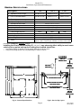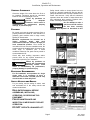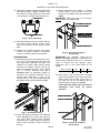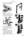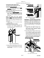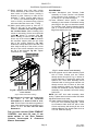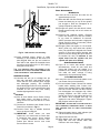
1
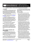
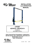
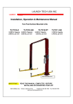
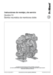
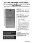
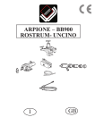
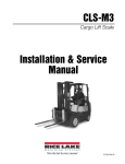
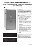
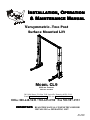
INSTALLATION, OPERATION
& MAINTENANCE MANUAL
Versymmetric Two Post
TM
Surface Mounted Lift
MODEL CL9
9,000 LBS. CAPACITY
2250 LBS. PER ARM
200 Cabel Street, P.O. Box 3944 Louisville, Kentucky 40201-3944
Email:[email protected] Web site:www.challengerlifts.com
Office 800-648-5438 / 502-625-0700 Fax 502-587-1933
IMPORTANT: READ THIS MANUAL COMPLETELY BEFORE
INSTALLING or OPERATING LIFT
Rev. 10/9/03
A1151.doc
Model CL9
Installation, Operation and Maintenance
GENERAL SPECIFICATIONS
See Figure 1
CL9
CL9-1
CL9-2
A
Adjustable Column Height
11’-8” or 11’-2”
12’-8” or 12’-2”
13’-8” or 13’-2”
B
Floor to Overhead Switch
11’-2” or 10’-8”
12’-2” or 11’-8”
13’-2” or 12’-8”
C Rise Height (Screw Pads Highest Position)
D Cylinder Height (Full Stroke)
E Adjustable Overall Width
F Screw Pad Height
G Inside of Columns
Drive Thru Clearance
Ceiling Height Required
* Maximum Capacity
** Lifting Time
** Lowering Time
Motor
74 5/8”
11’-11”
11’-2” or 10’-8“ or 10’-2”
4 ¼” to 6 ¾”
109” or 103” or 97”
89” or 83” or 77”
12’-0”
12’-9”
13’-9”
9,000 lbs. (2250 lbs. Per Arm)
60 Sec. (approximate)
30 Sec. (approximate)
2HP, Single Phase, 60Hz, 208/230
Optional – 2HP, Three Phase, 50/60Hz, for 208 or 230 or 460
Dimensions in BOLD are “Standard” settings.
Installing the lift at a narrow setting (E = 103” or 97”) may adversely affect ability to reach some
vehicle pick up points and requires cutting the overhead shutoff bar.
*
**
Lift capacity ratings are based on loads equally distributed on all four arms.
Lifting and lowering speeds may vary depending on weight of vehicle.
6' TO NEAREST
OBSTRUCTION
OR 7' TO
NEAREST WALL
108" [9'-0"]
MIN.TO
NEAREST
OBSTRUCTION
DRIVE ON
DIRECTION
101 2" REF
G
D
COLUMN BASE PLATES
A
B
(INSIDE COLUMN TO COLUMN)
SEE CHART ABOVE
(USE AS REFERENCE ONLY)
SEE CHART ABOVE
C
144" [12'-0"]
MIN. TO
NEAREST
OBSTRUCTION
F
E
Fig 1a - General Specifications
Fig1b - Service Bay Layout
Page 2
Rev. 10/9/03
A1151.doc
Model CL9
Installation, Operation and Maintenance
VERTICAL CLEARANCE
Safety decals similar to those shown here are
found on a properly installed lift. Be sure that all
safety decals have been correctly installed on the
Power Unit reservoir. Verify that all authorized
operators know the location of these decals and
fully understand their meaning. Replace worn,
faded, or damaged decals promptly.
Do not attempt to raise a
WARNING vehicle on the lift until the
lift has been correctly
installed and adjusted as described in this
manual.
Check the height of the area where the lift is to
be installed. Clearance should be calculated
based on the full raised height of the lift.
Failure by purchaser to
adequate
WARNING provide
clearance could result in
unsatisfactory lift performance, property
damage, or personal injury.
FLOORING
Be certain you have the proper concrete floor to
properly handle the loaded lift. Floor should be in
generally good condition with no large cracks,
spalling or deterioration.
Minimum requirements for concrete are 4
inches
minimum
depth,
with
steel
reinforcement, 3500 psi, cured for 28 days per
local commercial practice. Floor should be
level within 3/8 inch over the installation area. No
anchors should be installed within 8 inches of any
crack, edge, or expansion joint. If these
conditions cannot be met, pads can be poured to
accommodate the lift.
Check with local building inspectors and/or
permits office for any special instructions or
approvals required for your installation.
Failure by purchaser to
WARNING provide the recommended
mounting surface could
result in unsatisfactory lift performance,
property damage, or personal injury.
ELECTRICAL REQUIREMENTS
For lift installation and operation for single
phase units, it is necessary to have a
dedicated circuit with a double pole 25 amp
circuit breaker or time delay fuse.
SAFETY NOTICES AND DECALS
For your safety, and the safety of others, read
and understand all of the safety notices and
decals included here.
READ ENTIRE MANUAL BEFORE
ASSEMBLING, INSTALLING,
OPERATING, OR SERVICING THIS
EQUIPMENT.
PROPER MAINTENANCE AND
INSPECTION IS NECESSARY FOR SAFE
OPERATION.
DO NOT OPERATE A DAMAGED LIFT.
Page 3
Rev. 10/9/03
A1151.doc
Model CL9
Installation, Operation and Maintenance
RECEIVING
The shipment should be thoroughly inspected as
soon as it is received. The signed bill of lading is
acknowledgement by the carrier of receipt in
good condition of shipment covered by our
invoice.
If any of the goods called for on this bill of lading
are shorted or damaged, do not accept them until
the carrier makes a notation on the freight bill of
the shorted or damaged goods. Do this for your
own protection.
NOTIFY Challenger Lifts AT ONCE if any
hidden loss or damage is discovered after
receipt.
IT IS DIFFICULT TO COLLECT FOR LOSS OR
DAMAGE AFTER YOU HAVE GIVEN THE
CARRIER A CLEAR RECEIPT.
File your claim with Challenger Lifts promptly.
Support your claim with copies of the bill of
lading, freight bill, and photographs, if available.
INSTALLATION
IMPORTANT: Always wear safety glasses while installing lift.
TOOLS (MINIMUM REQUIRED)
a. Banding Cutter
b. Tape measure, 16ft
c. Chalk line
d. 4ft level
e. 10” adjustable wrench
f. Standard open end wrenches 7/16”, 1/2",
(2) 9/16”, (2) 11/16”, 3/4"
g. 5/16” allen wrench
h. Needle nose pliers
i. Hammer drill with 3/4” diameter carbide
tipped bit
j. 2lb hammer
k. Torque wrench: 150 foot pounds minimum
with 1 1/8” socket
l. 12 ft. Step ladder
m. Pull wire or fish tape
n. Anti-Seize lubricant (for arm pins)
o. 3/4” O.D. Pipe cutter (if installing lift at narrow
width setting)
Component Packing List
PART #
QTY/
LIFT
A1001-P
1
Power Column Ass’y
A1001-I
1
Idler Column Ass’y
A1060
1
Overhead (Mid Section)
A1061
2
Overhead (End Section)
A1005
1
Hardware Box
A1002
1
Arm Pack
A1055-0
A1055-1
2
LAYOUT
1) Layout the service bay according to the
architect’s plans or owners instructions (see
Fig 1b). Be certain that the proper conditions
exist, see page 3.
2) Assemble column extension to column using
3/8-16 x 3/4" lg Hex flange head bolt. repeat
for opposite column and extension.
3) Erect both column assemblies. Align the
notches in column base, Fig 2, with the
installation lines. (HINT: It may be easier to
install the lower synchronizer cable, Fig 7b,
before columns are raised)
DESCRIPTION
Column Extension for CL9
ANCHORING
Column Extension for CL9-1
4) The anchor bolts must be installed at least 8
inches from any crack, edge, or expansion
joint.
5) Use a concrete hammer drill with a 3/4 inch
carbide bit. Tip diameter should conform to
ANSI Standard B94.12-1977 (.775 to .787).
Do not use excessively worn bits or bits
which have been incorrectly sharpened. A
core bit may be necessary if an obstruction is
encountered. Never substitute with shorter
anchor.
A1055-2
Column Extension for CL9-2
A1003-0
Sync Cable Pack for CL9
A1003-1
1
A1003-2
Sync Cable Pack for CL9-1
Sync Cable Pack for CL9-2
36035
1
Overhead Shut-Off Bar Ass’y
36027
1
Mercury Switch
A1004
1
Hydraulic Hose Pack
A1201-15
A1203-15
1
Power Unit – 1 Phase
Power Unit – 3 Phase
A1150
1
Literature Pack
6) Recheck “Inside of Columns” dimension,
Fig 1. Drill the anchor holes using the base
plate as a template. Drill through the floor if
possible or to a depth of 5 inches minimum.
7) Vacuum dust from the hole for proper holding
power.
Page 4
Rev. 10/9/03
A1151.doc
Model CL9
Installation, Operation and Maintenance
8) Shim both columns to plumb using the shims
provided as shown in Fig 2. DO NOT shim
more than 1/2" at any given point. Use a level
no less than 24” in length to plumb columns.
ALIGNMENT NOTCH
13) Install Overhead Limit Switch to Power
Column using (1) 3/8” pivot pin, (1) 3/8” flat
washer and (1) hairpin cotter pin as shown in
Fig 4a.
IMPORTANT: switch tube cord is to be oriented
above pivot pin as shown below.
HAIRPIN COTTER PIN
3/8" FLAT WASHER
TUBE CORD MUST BE
ABOVE PIVOT PIN FOR
PROPER ORIENTATION
ALIGNMENT NOTCH
Fig 2 – Column Shimming
9) Assemble washer and nut to anchor with nut
just below impact section of bolt. Drive
anchor into hole until nut and washer contact
base.
10) Tighten power column anchors and recheck
column for plumb. Reshim if necessary.
Torque to 150 foot pounds to set anchors.
OVERHEAD BEAM
11) Assemble the (3) part overhead with (12) 3/816 x 3/4” lg hex flange head bolts and (12)
hex flange nuts using Fig 1 on page 2 as
reference for proper width. Before raising
overhead into position install 4 each (2 per
column) hex flange bolts and nuts in middle
hole of column extension (see Fig 3
Installation Aid) for temporary support of
overhead. Lift overhead assembly up into
position and install with 6 each (3 per
column) 3/8-16 x 3/4” lg hex flange bolts and
hex flange nuts per side as shown in Fig 3.
PROPER ORIENTATION
Fig 4a – Overhead Limit Switch
Sub-Assembly
IMPORTANT: The “standard” setting for the
INSIDE OF COLUMNS dimension is 109 inches. If
the lift is to be installed at 103” or 97”, use tubing
cutter to shorten the end opposite where
attachment hole is. See chart below for cut
length.
Inside of Column
Shutoff Bar Length
109”
103”
97”
107 ¼”
101 ¼”
95 ¼”
14) Insert shut-off bar in switch tube on power
column side and take other end to idler side.
Attach shut-off bar to idler column with (1)
3/8” pivot pin, (6) 3/8” flat washer and (1)
hairpin cotter pin as shown in Fig 4b.
Insure that both switch tube and shut-off
assemblies pivot freely for proper
operation.
HAIRPIN COTTER PIN
(6) 3/8" FLAT WASHERS
Fig 3 – Overhead Assembly
12) Check idler column shimming. Use additional
shims (see Fig. 2) to remove any gaps that
may have been created while installing
overhead beam. Tighten anchor bolts and recheck column for plumb. Torque to 150 foot
pounds.
Page 5
SHUTOFF BAR
3/8" PIVOT PIN
Fig 4b – Overhead Limit Switch
Sub-Assembly
Rev. 10/9/03
A1151.doc
Model CL9
Installation, Operation and Maintenance
15) Assemble the sheaves, spacers and washers
onto the sheave pin as shown in Fig 5. Set in
cradle with all assembly parts between the
two plates.
SHORT SHEAVE SPACER
WASHER
SHEAVE
SHEAVE PIN
WASHER
LONG SHEAVE SPACER
WASHER
SHEAVE
WASHER
SHORT
SHEAVE
SPACER
Fig 5 – Sheave Assembly
LOCKING PAWL
16) Install Power Column locking pawl and lock
release clevis with 5/8” diameter x 1 1/2” lg
shoulder bolt and 1/2”-13 nylon lock nut,
Fig. 6. Attach 3/8” O.D. extension spring to
upper hole in locking pawl and other end to
hole in bracket welded to column.
Fig 7a – Cable Routing
Fig 7b – Attaching Cable from Below
Fig 6 – Locking Pawl Assembly
17) Attach ½” O.D. extension spring to hole
located on bottom side of Idler Column lock
pawl and install using 5/8” shoulder bolt and
lock nut, Fig 6. Attach 3/8” O.D. spring the
same as Power side.
SYNCHRONIZER CABLES
18) Manually raise the carriages approximately
32 inches to gain access to the cable-tie-off
tabs located on the carriage ladder. Insure
that the top of the hydraulic cylinder is out of
the way but still retained in the opening of the
top plate of the carriage as shown in Fig 7a.
19) Route synchronizing cables using Fig 7a and
attach ends to cable-tie-off tabs using Fig’s
7b & 7c.
Page 6
Fig 7b – Attaching Cable from Above
Rev. 10/9/03
A1151.doc
Model CL9
Installation, Operation and Maintenance
SYNCHRONIZER CABLE ADJUSTMENT
This method requires adjusting the cable
ends at the power column only
20) At the power side carriage adjust the Cable
from Above until the power column carriage
is 1/8” off its locking pawl.
NOTE: The Lower Cable should NOT be tight
before beginning this step.
21) Now adjust the Cable from Below until the
power column carriage contacts its locking
pawl. Grab the back of the locking pawl and
wobble it. Continue tightening until the lock
pawl is tight.
When the cables have been adjusted
properly, neither locking pawl will wobble by
hand. (tighten the power column lower cable to
tighten the power column locking pawl or the
power column upper cable for the idler column
locking pawl.
22) Tighten the thin Jam Nuts against the Cable
Adjustment Nut.
POWER UNIT & HYDRAULIC HOSE
23) Mount Power Unit to power column as shown
in Fig 8. The mounting hardware, (4)
5/16”-18 hex nuts, are pre-installed on power
unit mounting bracket.
BULKHEAD BRANCH TEE
MALE #6 (9/16-18)
SAE (JIC) 37° FLARE
(FACTORY INSTALLED)
Fig 9 – Hydraulic Hose from Power Unit to
Power Column.
IMPORTANT – To insure proper hose fitting
seal without damage to the fitting follow this
procedure for each hose connection: Screw
flared fitting on finger tight. Rotate flared fitting 1
1/2 hex flats (90 deg.). Back the flared fitting off
one full turn. Again tighten flared fitting finger
tight, then rotate flared fitting 1 1/2 hex flats (90
deg.).
25) Thread power unit hydraulic hose (22” lg in
hardware box) into elbow on power unit.
Thread opposite end of hose into male #6
fitting (factory installed) attached to power
column as shown in Fig 9.
26) From Idler Column route the hydraulic hose
(factory installed from cylinder to top of column)
up to Overhead. LOOSEN FACTORY INSTALLED
CLAMP AT TOP OF IDLER COLUMN AND GENTLY PULL UP
ANY SLACK FROM HOSE. Install a hose clamp in
column extension and in overhead beam with
(1) 3/8”-16 x 3/4" lg. hex flange bolt and hex
flange nut per clamp as shown in Fig 10a.
5/16"-18 HEX NUT
(4) REQUIRED
HYDRAULIC HOSE CLAMP WITH
3/8"-16 HEX FLANGE BOLT & NUT
SNAKE EXCESS HOSE
IN OVERHEAD WHEN
INSTALLING AT NARROW
OR LOWERED SETTING
Fig 8 – Power Unit Mounting
24) Attach hydraulic elbow fitting (in hardware box)
threading the 9/16-18 O-ring end to power
unit. See Fig 9. CAUTION not to damage
rubber O-ring.
Fig 10a – Hydraulic Hose from Idler Column to
Overhead.
(Sync cables removed for clarity)
Page 7
Rev. 10/9/03
A1151.doc
Model CL9
Installation, Operation and Maintenance
27) Route hydraulic hose from Idler column
across Overhead to the Power Column and
down inside of Power Column (routing is
identical to Idler Column) to male #6 JIC
bulkhead “T” fitting. Loosely attach hose to
“T”. If this is an extended height lift (model
CL9-1 or CL9-2), an extension hose (supplied)
will connect the Idler hose to the “T” fitting.
28) While gently pulling slack up from the “T”
fitting to the top of the power column
extension, twist the hose until it lays flat in
the overhead beam. (When installing lift at
narrow or low setting, excess hose should be
snaked in bottom of overhead, Fig 10a.
When installing at narrow and low setting,
form a loop in the column extension between
the overhead support plate and the inside
wall of the column extension, Fig 10b.)
Install hose clamps identical to idler side, one
hose clamp at the top of the column, one at
the top of the column extension and one at
the end of the overhead. Fig 10b. Tighten
connection at “T” fitting.
SNAKE EXCESS HOSE
IN OVERHEAD WHEN
INSTALLING AT NARROW
OR LOWERED SETTING
LOCK RELEASE
30) Attach Mechanical Lock Release Cable
Assembly to Power Column Lock Release
Clevis using the 3/16” diameter x 1/2" long
pin and (2) “C” clip retainers, Fig 11.
31) Insert threaded sleeve portion of cable
assembly in slot located on tab above locking
pawl, Fig 11. One jam nut should be located
on each side of tab. Position threaded sleeve
with ½” of thread below tab as indicated in
Fig 11 and tighten jam nuts.
HYDRAULIC HOSE CLAMP
WITH 3/8"-16 HEX FLANGE
BOLT & NUT
Fig 11 – Power Column Lock Assembly
LOOP EXCESS HOSE
IN COLUMN EXT. WHEN
INSTALLING AT NARROW
AND LOWERED SETTING
Fig 10b – Hydraulic Hose from Overhead to
Power Column.
(Sync cables removed for clarity)
29) BE CERTAIN ALL FITTINGS AND CONNECTIONS
IT IS THE
TIGHT.
ARE
INSTALLERS
RESPONSIBILITY TO INSURE SYSTEM IS LEAKFREE. Fill the Power Unit with three gallons of
clean 10wt anti-foam anti-rust hydraulic oil or
Dexron III ATF. DO NOT USE OILS WITH
DETERGENTS.
32) Route opposite end of cable assembly up left
side of Power Column and into column
through access slot (3/8”x4” Lg.) in bottom of
Column Extension. Following the path of the
hydraulic line, route cable assembly across
overhead clear of moving parts and back out
through access slot in bottom of idler side
column extension (again use left slot when
viewed from outside of column). Attach Cable
Assembly to the hydraulic hose with loosely
fit wire ties.
NOTE: DO NOT kink cable assembly when
routing. Tighten and trim wire ties after final cable
adjustments have been made.
33) Attach Adhesive-Backed Tab to Idler Column
left of the lock assembly (Fig 12). Route
Lock Release Cable down left side of Idler
Column and secure with loosely fit wire tie to
Adhesive-Backed Tab. Attach Cable clevis to
1/2" O.D. Extension Spring.
FOR LIFTS WITH OPTIONAL DUAL PENDANT
CONTROL, SKIP STEPS 26 THRU 31 AND
REFER INSTEAD TO THE “DUAL PENDANT
CONTROL INSTALLATION & OPERATION
MANUAL SUPPLEMENT”.
Page 8
Rev. 10/9/03
A1151.doc
Model CL9
Installation, Operation and Maintenance
FINAL ADJUSTMENTS
Fig 12 – Idler Column Lock Assembly
34) Insert threaded sleeve portion of cable
assembly in slot located on tab below lock
pawl, Fig 12. With one jam nut located on
each side of tab, adjust the threaded sleeve
to begin to pull tension on the ½” O.D. spring.
Snug jam nuts by hand.
THE LOCK RELEASE CABLE ADJUSTMENT IS NOT
COMPLETE UNTIL THE LIFT HAS BEEN LOWERED AND
“FINAL ADJUSTMENTS” HAVE BEEN MADE.
ARM INSTALLATION
35) Lubricate the arm pin or carriage arm pin
hole with “anti-seize” and install the arms.
Insure that the arm restraint gears engage
and disengage properly. Arm restraints
should disengage when lift is fully lowered. If
any binding occurs, insure that the large gear
mounted to the arm has been factory
installed tight against the arm pin.
ELECTRICAL
36) Wire tie Limit Switch cord to Power Column
hose inside column and down to hose “T”
fitting. Route cord out slot and tie to Power
Unit hose.
37) Connect the Overhead Limit Switch Cord to
Power Unit as shown in Fig 13.
38) Connect Power Unit to suitable electrical
source as shown in Fig 13.
39) IMPORTANT: AFTER WIRING HAS BEEN
COMPLETED, TEST OPERATION OF POWER UNIT
& OVERHEAD LIMIT SWITCH. W HILE RAISING
LIFT, OPERATE OVERHEAD SHUTOFF BAR.
POWER UNIT MOTOR SHOULD STOP WHEN
SHUTOFF BAR IS RAISED.
Page 9
HYDRAULICS
40) Lower the lift to the floor and raise the lift
approximately one foot.
41) Start with Idler side first. Slowly and carefully
loosen the bleed plug on top of the cylinder
just enough to allow the entrapped air to
escape. Repeat for power side.
42) Energize the power unit and raise 6 inches.
Repeat previous step until no air comes out
of cylinder.
43) Pressure test hydraulic system. Energize
power unit, raise lift to full rise and continue
to run motor for additional 10 seconds.
(NOTE: pressure relief will make a high pitch
squeal sound for these 10 seconds.) Check
hydraulic system for leaks.
44) Energize power unit again for 10 seconds.
With a clean rag, wipe down both cylinder
rods. (The cylinders are shipped with a small
amount of clear anti-corosive lubricant that
will be forced out through the wiper when the
lift reaches full rise.) If lubricant is not
wiped clean from the cylinder rod, the
cylinder will apear to be leaking.
SYNCHRONIZING CABLES
45) Cycle lift to insure that latches operate
simultaneously. Lower lift onto locks and
insure that neither lock will wobble (it is
possible for one carriage to be resting on its
lock while the other carriage is being
supported by the synchronizing cable).
LOCK RELEASE CABLE
46) Lower lift to the floor and snap plastic cover
over Power Column lock assembly.
47) Pull and release Power Column lock release
handle while watching Idler Column lock.
Adjust lower threaded sleeve cable adjuster
jam nuts on Idler Column until Idler Column
lock disengages and engages fully. When
properly adjusted, the idler column lock
should just come to rest against the back of
the column when engaged and fully out
against the tab when disengaged. Tighten
Idler Column lower tab jam nuts.
IMPORTANT: IF IDLER SIDE LOCK PAWL DOES NOT
FULLY DISENGAGE, DAMAGE MAY RESULT TO IDLER
SIDE CARRIAGE AND OR CABLE SYNCHRONIZING
SYSTEM.
48) Tighten threaded sleeve cable adjuster jam
nuts and install lock release knob.
49) Tighten and trim wire ties.
50) Snap plastic cover over Idler lock assembly
(align idler side lock release cable with
notches in lock cover flange).
Rev. 10/9/03
A1151.doc
Model CL9
Installation, Operation and Maintenance
Wiring Diagram
* After wiring has been completed, test operation of Power Unit & Overhead Limit Switch. While raising
lift, operate Overhead Shutoff Bar. Power Unit Motor should stop when Shutoff Bar is raised.
EACH LIFT SHOULD HAVE A DEDICATED CIRCUIT WITH A
DOUBLE POLE (THREE POLE FOR 440-480V) BREAKER
OR TIME DELAY FUSE SIZED ACCORDING TO THE
FOLLOWING CHART
2Hp
1Ø
208-240V
3Ø
208V
3Ø
220-240V
3Ø
440-480V
25amp
15amp
15amp
5amp
* WIRING MUST COMPLY WITH NEC AND ALL LOCAL ELECTRICAL CODES *
RAISE
PUSH BUTTON
(N.O.)
FOR SINGLE PHASE
"NORM.
OPEN"
"COMMON"
BLACK
OVERHEAD
LIMIT
SWITCH
BLACK
M
YELLOW
HELD
CLOSED
L1 (BLACK)
1Ø 208-240VAC
SUPPLY
WHITE
BLACK
1Ø 208-240VAC
BLUE
L2 (WHITE)
GROUND
GROUND SCREW IN
MOTOR WIRING BOX
OVERHEAD LIMIT SWITCH AND CONTACTOR
FOR OVERHEAD MODELS ONLY
FOR THREE PHASE
CONTACTOR ENCLOSURE TO BE FIELD MOUNTED
ON POWER COLUMN (CENTERED SIDE-TO-SIDE TO
AVOID INTERFERENCE WITH SLIDE BLOCKS)
OVERHEAD
LIMIT
BLACK
MOTOR ENCLOSURE
WHITE
HELD
CLOSED
A1
SEE
NOTE
A2
COIL
RAISE
SWITCH
L1 T1
2 1
T1
L1
L2
3Ø
50/60Hz
SUPPLY
FACTORY WIRED FOR
208−240V
4 3
L2 T2
L3
6 5
L3 T3
BLACK
T7
T2
BLACK
BLACK
T8
T3
M
T4
T5
T6
50/60 Hz
T9
GREEN
RAISE
SWITCH
NOTES:
RECONNECTIONS FOR
440−480V
1) MOTOR IS FACTORY WIRED FOR 208V OR
220-240V SUPPLY
2 1
2) MOTOR CONNECTIONS MUST BE RECONFIGURED
PER THIS DIAGRAM FOR 440-480V SUPPLY
3) CONTACTOR COIL RATING MUST MATCH SUPPLY
VOLTAGE (208V, 220-240V, OR 440-480V)
4 3
4) CONTACTOR MUST BE FIELD MOUNTED ON POWER
COLUMN (CENTERED SIDE-TO-SIDE TO AVOID
INTERFERENCE WITH SLIDE BLOCKS)
6 5
BLACK
BLACK
BLACK
T1
T2
T3
T4
M
50/60 Hz
T7
T5
T8
T6
T9
5) MOTOR ROTATION IS COUNTER CLOCKWISE
FROM TOP OF MOTOR
Fig 13 – Electrical Wiring Diagram
Page 10
Rev. 10/9/03
A1151.doc
Model CL9
Installation, Operation and Maintenance
OWNER/OPERATOR CHECKLIST
51) Demonstrate the operation of the lift to the
owner/operator and review correct and safe
lifting procedures using the Lifting It Right
booklet as a guide.
52) Complete the Installation Checklist/Warranty
Validation questionnaire with the owner.
Review the terms of the warranty registration
card, and return the card and a copy of the
questionnaires to:
Challenger Lifts, Inc.
200 Cabel Street
Louisville, KY. 40206
OPERATION PROCEDURE
SAFETY NOTICES AND DECALS
This product is furnished with graphic safety
warning labels, which are reproduced on
page 3 of these instructions. Do not remove
or deface these warning labels, or allow them
to be removed or defaced. For your safety,
and the safety of others, read and understand
all of the safety notices and decals included.
OWNER/EMPLOYER RESPONSIBILITIES
This lift has been designed and constructed
according to ANSI/ALI ALCTV-1998 standard.
The standard applies to lift manufactures, as well
as
to
owners
and
employers.
The
owner/employer’s responsibilities as prescribed
by ANSI/ALI ALOIM-2000, are summarized
below. For exact wording refer to the actual
standard provided with this manual in the
literature pack.
The Owner/Employer shall insure that lift
operators are qualified and that they are trained
in the safe use and operation of the lift using the
manufacturer’s operating instructions; ALI/SM
93 -1, ALI Lifting it Right safety manual; ALI/ST90 ALI Safety Tips card; ANSI/ALI ALOIM-2000,
American National Standard for Automotive LiftsSafety Requirements for Operation, Inspection
and Maintenance; ALI/WL Series, ALI Uniform
Warning Label Decals/Placards; and in case of
frame engaging lifts, ALI/LP-GUIDE, Vehicle
Lifting Points/Quick Reference Guide for Frame
Engaging Lifts.
Page 11
establish
The
Owner/Employer
shall
procedures to periodically inspect the lift in
accordance
with
the
lift
manufacturer’s
instructions or ANSI/ALI ALOIM-2000, American
National Standard for Automotive Lifts-Safety
Requirements for Operation, Inspection and
Maintenance; and the employer shall insure that
the lift inspectors are qualified and that they are
adequately trained in the inspection of the lift.
The
Owner/Employer
shall
establish
procedures to periodically maintain the lift in
accordance
with
the
lift
manufacturer’s
instructions or ANSI/ALIOIM-2000, American
National Standard for Automotive Lifts-Safety
Requirements for Operation, Inspection and
Maintanence; and the employer shall insure that
the lift maintenance personnel are qualified and
that they are adequately trained in the
maintenance of the lift.
The Owner/Employer shall maintain the
periodic inspection and maintenance records
recommended by the manufacturer or ANSI/ALI
ALOIM-2000, American National Standard for
Automotive
Lifts-Safety
Requirements
for
Operation, Inspection and Maintenance.
The Owner/Employer shall display the lift
manufacturer’s operating instructions; ALI/SM
93 -1, ALI Lifting it Right safety manual; ALI/ST90 ALI Safety Tips card; ANSI/ALI ALOIM-2000,
American National Standard for Automotive LiftsSafety Requirements for Operation, Inspection
and Maintenance; and in the case of frame
engaging lift, ALI/LP-GUIDE, Vehicle Lifting
Points/Quick Reference Guide for Frame
Engaging Lifts; in a conspicuous location in the
lift
area
convenient
to
the
operator.
Rev. 10/9/03
A1151.doc
Model CL9
Installation, Operation and Maintenance
LIFTING A VEHICLE
MAINTENANCE
1) Insure that the lifting arms are parked, out to
full drive thru position.
2) Position the vehicle in the service bay so that
the vehicle’s center of gravity is on a line
between the two columns, and so the vehicle
is centered between the two columns.
To avoid personal injury, permit only qualified
personnel to perform maintenance on this
equipment.
The following maintenance points are suggested
as the basis of a preventive maintenance
program.
The actual maintenance program
should be tailored to the installation. See
ANSI/ALI ALOIM booklet for periodic inspection
checklist and maintenance log sheet.
DO NOT EXCEED 2250 POUNDS PER ARM.
DO NOT ATTEMPT TO LIFT THE VEHICLE WITH
ONLY TWO ARMS, AS THIS WILL VOID THE
WARRANTY
INSURE THAT THE HIGHEST POINT ON THE
VEHICLE WILL CONTACT THE OVERHEAD LIMIT
SWITCH BAR.
DO NOT PLACE THE VEHICLE IN THE SERVICE
BAY BACKWARDS.
REFER TO THE VEHICLE MANUFACTURERS
SERVICE MANUAL, TECHNICAL BULLETINS,
“VEHICLE LIFTING POINTS GUIDE” (ALI/LPGUIDE) OR OTHER PUBLICATIONS TO LOCATE
THE RECOMMENDED LIFTING POINTS.
3) Position the arms and adapters so all four
pads contact the vehicle simultaneously.
The vehicle should remain level during lifting.
4) Raise the lift until all four wheels are off the
ground. Test the stability of the vehicle by
attempting to rock the vehicle. Check adapters
for secure contact with vehicle lift points. If the
vehicle seems unstable, lower the lift and
readjust the arms. If the vehicle is stable,
raise the vehicle to a height a few inches
above the desired working height.
5) Lower the vehicle until the safety latches on
both columns engage. The vehicle should
remain level when both latches are engaged.
If one side engages and the other continues to
descend, stop lowering the vehicle, raise it
several inches, and try again to engage both
latches.
Always lower lift into locks before entering
the area beneath the vehicle.
Always use safety stands when removing or
installing heavy components.
• If lift stops short of full rise or chatters, check
fluid level and bleed both cylinders per
Installation Instructions.
• Replace all Safety, Warning or Caution Labels
if missing or damaged (See Installation
instructions page 3.)
Daily
• Keep lift components clean.
• Check for loose or broken parts.
• Check hydraulic system for fluid leaks.
• Check adapters for damage or excessive wear.
Replace as required with genuine Challenger
Lifts parts.
• Check lock release activation. When properly
adjusted, the idler column lock should rest
firmly against the back of the column when
engaged and against the spring mount tab
when disengaged.
Weekly
• Check synchronizer cables and sheaves for
wear. Replace as required with genuine
Challenger Lifts parts.
• Check lock release cable adjustment per
Installation Instructions step 42.
IMPORTANT: IF IDLER SIDE LOCK PAWL DOES
NOT FULLY DISENGAGE, DAMAGE MAY RESULT
TO IDLER SIDE CARRIAGE AND OR CABLE
SYNCHRONIZING SYSTEM.
• Check synchronizer cable tension per
Installation Instructions. Adjust if necessary.
Monthly
• Torque concrete anchor bolts to 80 ft-lbs.
LOWERING A VEHICLE
1) Insure that the area under the vehicle is clear
of personnel and tools.
2) Raise the vehicle until both latches are free.
3) Disengage the latches by pulling down and
holding the lock release lever.
4) Lower the vehicle by depressing the lowering
valve handle.
5) Continue to lower the vehicle until the
carriages stop against the base plate. Retract
the extension arms, and park them.
Page 12
• Check overhead shutoff switch. While raising
lift, operate overhead shutoff bar. Power Unit
motor should stop when bar is raised.
• Lubricate carriage slide tracks with heavy
viscous grease. (Grease all (4) corners of both
columns.)
If any problems are encountered, contact
your local service representative.
Rev. 10/9/03
A1151.doc
Model CL9
Installation, Operation and Maintenance
PARTS BREAKDOWN
Fig A. Column & Overhead
ITEM #
1
PART #
QTY/LIFT
A1010-P
1
A1010-I
1
A1055-0
2
A1055-1
DESCRIPTION
POWER COLUMN WELD
IDLER COLUMN WELD
COLUMN EXTENSION WELD – CL9
2
A1055-2
COLUMN EXTENSION WELD – CL9-1
COLUMN EXTENSION WELD – CL9-2
3A
A1060
1
3B
A1061
2
OVERHEAD CHANNEL (END SECTION)
4
36074
1
SHUTOFF BAR
5
31129
1
PAD
6
36027
1
OVERHEAD LIMIT SWITCH
7
A1064
2
3/8 DIA x 1 7/8 Lg. CLEVIS PIN (SHUTOFF BAR)
8
40124
2
HAIRPIN COTTER PIN
9
31036
7
3/8" FLAT WASHER
10
A1153
36
3/8-16NC HEX.FLG.HD.C.S X 3/4" Lg.
11
A1154
36
3/8-16NC HEX.FLG.NUT
OVERHEAD CHANNEL (MID SECTION)
Replace all worn or broken parts with genuine Challenger Lifts Inc. parts.
Contact your local Challenger Lifts Parts Distributor for pricing and availability.
(Call Challenger Lifts Inc. (502) 625-0700 for the Parts Distributor in your area)
Page 13
Rev. 10/9/03
A1151.doc
Model CL9
Installation, Operation and Maintenance
PARTS BREAKDOWN (continued)
Fig B. Lock
FOR LIFTS EQUIPPED WITH
DUAL PENDANT CONTROL
REFER TO SEPERATE
"DUAL PENDANT CONTROL
MANUAL SUPPLEMENT"
ITEM #
PART #
A1135-0
20
A1135-1
QTY/LIFT
1
A1135-2
DESCRIPTION
LOCK RELEASE CABLE ASSEMBLY – CL9-0
LOCK RELEASE CABLE ASSEMBLY – CL9-1
LOCK RELEASE CABLE ASSEMBLY – CL9-2
21
A1140
2
LOCK PAWL
22
A1133
2
LOCK COVER
23
30020
2
LOCK PIN (5/8 x 1 1/2" Lg. SHOULDER BOLT)
24
37013
2
LOCK PIN RETAINER (1/2-13NC HEX LOCK NUT)
25
37119
1
CLEVIS PIN KIT
26
A1131
2
LOCK SPRING (3/8" O.D.)
27
A1132
1
CABLE SPRING (1/2" O.D.) – Idler side ONLY
28
A1141
1
LOCK RELEASE CLEVIS ASSEMBLY – Power side ONLY
29
36096
1
BALL HANDLE – Power side ONLY
Replace all worn or broken parts with genuine Challenger Lifts Inc. parts.
Contact your local Challenger Lifts Parts Distributor for pricing and availability.
(Call Challenger Lifts Inc. (502) 625-0700 for the Parts Distributor in your area)
Page 14
Rev. 10/9/03
A1151.doc
Model CL9
Installation, Operation and Maintenance
PARTS BREAKDOWN (continued)
Fig C. Hydraulics
ITEM #
35
PART #
A1201-15
A1203-15
QTY/LIFT
1
DESCRIPTION
POWER UNIT 1ph, 60 Hz, 208-230V
POWER UNIT 3ph, 60 Hz, 208-230/460V
36
16167
1
HYD ELBOW, 9/16 O-RING MALE TO #6 MALE FLARE
37
A1123-PU
1
HYD HOSE ASSEMBLY, POWER UNIT (22” LONG)
38
A1120
1
BULKHEAD TEE, #6 MALE 37 DEGREE FLARE
39101-024
1
COLUMN EXTENSION HOSE, CL9-1 (24” LONG)
39
39101-048
1
COLUMN EXTENSION HOSE, CL9-2 (48” LONG)
40
A1123-I
1
HYD HOSE ASSEMBLY, IDLER COLUMN (326” LONG)
41
A1122-12
7
HOSE CLAMP
42
16138
2
CYLINDER (68” STROKE X 2” BORE)
43
A1121
2
STRAIGHT ADAPTER, 9/16 MALE O-RING TO #6 MALE FLARE
44
A1123-P
1
HYD HOSE ASSEMBLY, POWER COLUMN (81” LONG)
Replace all worn or broken parts with genuine Challenger Lifts Inc. parts.
Contact your local Challenger Lifts Parts Distributor for pricing and availability.
(Call Challenger Lifts Inc. (502) 625-0700 for the Parts Distributor in your area)
Page 15
Rev. 10/9/03
A1151.doc
Model CL9
Installation, Operation and Maintenance
PARTS BREAKDOWN (continued)
Fig D. Synchronizer
ITEM #
PART #
QTY/LIFT
A1115-0
50
A1115-1
DESCRIPTION
SYNCHRONIZER CABLE – CL9-0 (32’-8”)
2
A1115-2
[ Cable Pack #A1003-0 ]
SYNCHRONIZER CABLE – CL9-1 (34’-8”)
[ Cable Pack #A1003-1 ]
SYNCHRONIZER CABLE – CL9-2 (36’-8”)
[ Cable Pack #A1003-2 ]
51
A1116
4
½-20NF HEX NUT
52
A1117
4
½-20NF HEX JAM NUT
53
A1041
6
SHEAVE ASSEMBLY (3 ½” DIA. X ¼” GROOVE)
54
A1062
2
SHEAVE PIN
55
A1063-S
4
SHORT SHEAVE SPACER
56
A1063-L
2
LONG SHEAVE SPACER
57
36013
10
1" I.D. SPACER WASHER
58
36014
2
1" EXT. RETAINING RING
Replace all worn or broken parts with genuine Challenger Lifts Inc. parts.
Contact your local Challenger Lifts Parts Distributor for pricing and availability.
(Call Challenger Lifts Inc. (502) 625-0700 for the Parts Distributor in your area)
Page 16
Rev. 10/9/03
A1151.doc
Model CL9
Installation, Operation and Maintenance
PARTS BREAKDOWN (continued)
Fig E. Carriage & Arms
ITEM #
PART #
QTY/LIFT
DESCRIPTION
70
A1025
2
CARRIAGE WELD
71
A1040
16
SLIDE BLOCK
72
A1078
4
ARM PIN WELD
73
A1091
2
REAR FEMALE ARM WELD
74
A1094-R
2
MALE ARM WELD (REAR)
75
A1104
4
FOOT PAD RUBBER INSERT
76
A1101
4
FOOT PAD WELD
77
31061
8
1/4-20 KEPS NUT
78
39111
4
FOOT PAD RETAINER RING
A1086-P
1
FRONT FEMALE ARM WELD (POWER)
A1086-I
1
FRONT FEMALE ARM WELD (IDLER)
80
A1094-F
2
MALE ARM WELD (FRONT)
81
31305
4
3/8 MALE ARM RETAINER SCREW
82
31037
4
3/8 LOCK WASHER
83
A1070
4
INNER GEAR
84
12568
8
3/8-16NCx1 Lg. HEX .FLG.LOCK.HD.C.S. GR.5 ZN PLT
85
A1075
4
PULL RING
86
A1073
4
SHAFT
87
31109
4
COMPRESSION SPRING (RESTRAINT SHAFT)
88
A1072
4
OUTER GEAR
89
36014
4
1" EXT. RETAINING RING
A1090
2
REAR ARM ASSY
(ITEMS NO: 73, 74, 81, 82)
A1085-P
1
FRONT ARM ASSY (POWER)
(ITEMS NO: 79, 80, 81, 82)
A1085-I
1
FRONT ARM ASSY (IDLER)
(ITEMS NO: 79, 80, 81, 82)
A1100
4
FOOT PAD ASSY
(ITEMS NO: 75, 76, 77)
A1077
4
ARM RESTRAINT SHAFT ASSY
(ITEMS NO: 85, 86, 87, 88, 89)
79
Replace all worn or broken parts with genuine Challenger Lifts Inc. parts.
Contact your local Challenger Lifts Parts Distributor for pricing and availability.
(Call Challenger Lifts Inc. (502) 625-0700 for the Parts Distributor in your area)
Page 17
Rev. 10/9/03
A1151.doc