1
English
1.3.2005
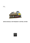
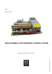
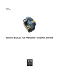
SERVICE MANUAL FOR FREQUENCY CONTROL SYSTEM
Control Master Plus - Hoisting
R&M Materials Handling, Inc.
4501 Gateway Boulevard
Springfield, Ohio 45502
P.: (937) 328-5100
FAX: (937) 325-5319
Read the instructions supplied with the product before installation and commissioning.
Keep the instructions in a safe place for future reference.
Table of content
1 GENERAL....................................................... 5
1.1 Technical data ........................................... 5
1.2 Type mark coding ...................................... 6
1.3 Basic description ....................................... 6
1.4 Main components ...................................... 7
1.5 Functional description ............................... 8
1.6 Control methods ........................................ 9
1.7 Description of the control methods ........... 10
1.7.1
1.7.2
1.7.3
EP2-control ....................................................10
EP3-control ....................................................10
MS4-control....................................................10
1.8 Mechanical brake control ........................ 11
1.9 EMC ......................................................... 11
2 INSTALLATION ............................................ 13
2.1 Cubicles .................................................... 13
2.2 Braking resistor......................................... 13
2.3 Power cabling .......................................... 13
2.3.1 Shielded motor cable ................................13
2.3.2 Double collectors .......................................13
2.3.3 Cable selection...........................................14
2.3.4 Cable protection .........................................14
2.3.5 Cable length ................................................14
2.3.6 Du/dt filters ..................................................15
2.4 Signal cabling ........................................... 15
2.4.1 Shielded signal cable ................................15
2.4.2 Reference signals ......................................15
2.4.3 Sensor bearing ...........................................15
2.4.4 Encoder........................................................15
2.5 EMC compatible grounding .................... 16
2.5.1 Construction connections ........................16
2.5.2 Cable connections .....................................16
2.5.3 Shielded control cables ............................16
3 COMPONENTS............................................. 17
3.1 Inverter ..................................................... 17
3.1.1 Power supply unit (PSU) ..........................18
3.1.2
Control unit (CSU)..........................................19
3.1.3 Basic I/O board (Slot A) ...........................20
3.1.4 Relay / Thermistor board (Slot B) ..........20
3.1.5 SSU Speed Supervision board (Slot C)20
3.1.6 I/O Extension board (Slot D) ...................21
3.2 Control voltage transformer .................... 21
3.3 Speed sensors ........................................ 22
3.3.1 Sensor bearing ...........................................22
3.3.2 Encoder........................................................23
3.3.3 Proximity switch .........................................24
3.3.4 Buffer amplifier KAE234...........................25
3.4 Brake controllers ..................................... 26
3.4.1
REC12 ...........................................................26
3.4.2 ESD141........................................................26
4 PARAMETER ADJUSTMENTS ................... 28
4.1 The display panel .................................... 28
4.1.1 Navigation on the control keypad ..........29
4.1.2
4.2
4.2.1
4.2.2
4.2.3
4.2.4
Value line editing............................................30
Storing and restoring parameters............. 31
User parameters ............................................31
Default parameters ........................................31
Keypad settings .............................................31
Factory settings..............................................31
5 PARAMETER DESCRIPTIONS ................... 32
6 FACTORY DEFAULT PARAMETERS......... 41
6.1 Factory default parameters for 100Hz
motors................................................................ 41
6.2 Factory default parameters for 120Hz
motors................................................................ 43
7 SPEED SUPERVISION SETTINGS ............. 45
7.1 Standard settings .................................... 46
7.1.1 Settings for sensor bearing............................46
7.1.2 Settings for pulse wheel speed sensor or
encoder (24 ppr) .........................................................46
7.2 Functional test run for SSU .................... 47
7.3 Settings for non-standard cases .............. 47
8 Multicare Function ...................................... 49
8.1 Connections ............................................. 49
8.2 Setup........................................................ 50
8.3 Test run without load................................ 50
9 START-UP PROCEDURE............................ 51
9.1 Visual checks .......................................... 51
9.2 Checks before the first test run .............. 51
9.3 Test run without load .............................. 51
2/83
R&M Materials Handling, Inc. reserves the right to alter or amend the above information without notice.
R&M Materials Handling, Inc.
4501 Gateway Boulevard
Springfield, Ohio 45502
P.: (937) 328-5100
FAX: (937) 325-5319
9.3.1 Functional test run for SSU .....................52
9.4 Test run with load .................................... 52
9.5 Test run with overload ............................. 52
9.6 After the test run ...................................... 52
10 TROUBLESHOOTING.................................. 53
10.1 Field repair actions .................................. 53
10.2 Typical functional problems .................... 53
10.3 Inverter fault codes .................................. 54
10.3.1 Fault time data record...............................57
10.3.2 Fault Counter .................................................58
10.4 Inverter Alarm codes ............................... 59
11 INVERTER TROUBLESHOOTING TABLE.. 60
12 SERVICE....................................................... 61
13 SPARE PARTS LIST FOR HOISTING
INVERTER ........................................................ 62
14 DRAWINGS .................................................. 64
14.1 Description of terminals .......................... 64
14.1.1 Power classes 002F - 011F ....................64
14.1.2 Power classes 015F - 055F ....................65
14.2 Layouts, dimensions and weights .......... 66
14.3 Circuit diagrams ...................................... 67
14.3.1 Internal wirings ...........................................67
14.3.2 Wiring colours .............................................68
14.4 Circuit diagrams for braking resistors .... 77
14.4.1 Internal wirings ...........................................77
14.5 Standard connections for pulse sensors.
82
3/83
R&M Materials Handling, Inc. reserves the right to alter or amend the above information without notice.
R&M Materials Handling, Inc.
4501 Gateway Boulevard
Springfield, Ohio 45502
P.: (937) 328-5100
FAX: (937) 325-5319
This manual rev 4.0 is for D2L rev 5.1 with software Ind2V070.
Before starting, read the instructions carefully.
Verify all of the connections are in accordance to the drawings.
Verify the motor supply is connected correctly, faulty connection will destroy the inverter.
Check the device cover is properly installed.
High voltages are present in this device. Switch the power off and after the display turns off,
wait 5 minutes before opening the cover.
Insulation resistance test with a megger requires special precautions.
Do not make any measurements inside the device when it is connected to the main supply.
Do not touch the components on the circuit boards. Static voltage discharge may cause
damage or destroy the IC-circuits.
Check all ventilation holes are clear and uncovered.
Check that hot air coming from the brake resistors does not cause any danger.
Do not make any inspections unless the supply has been disconnected by the main switch.
It is forbidden to use radiophones or portable phones near this device with the doors open.
All the doors and covers must be closed during crane operation.
Inverter is not intended to be used on a low-voltage public network, which supplies
domestic premises. Radio frequency interference is expected if used on such a network.
4/83
R&M Materials Handling, Inc. reserves the right to alter or amend the above information without notice.
R&M Materials Handling, Inc.
4501 Gateway Boulevard
Springfield, Ohio 45502
P.: (937) 328-5100
FAX: (937) 325-5319
1 GENERAL
1.1
Technical data
002F
003F
004F
005F
007F
011F
015F
018F
022F
030F
037F
045F
055F
Power (kVA) at 400V
Output current In (A)
4.5
6.5
5.5
8
7
10
9
13
13
18
17
24
22
32
29
42
33
48
40
60
50
75
60
90
75
110
Max. current 1min (A)
10
12
15
20
27
36
48
63
72
90
113
135
165
Power class
Overloadability
Max. output voltage
Supply
Supply voltage
Allowable voltage fluctuation
Nominal supply frequency
Signal input levels
Digital controls
Encoder feedback
Control features
Control method
Frequency control range
Frequency command
Limit switch functions
Speed control range
Speed accuracy
Extended speed range
Braking torque
Protections
Stall prevention
Motor overload protection
Overload protection
Undervoltage / blown fuse
Overvoltage protection
Momentary power loss
Inverter overtemperature
Mechanical brake
Braking transistor
Ground fault
Overspeed / stall,
Speed difference supervision
Ambient conditions
Ambient temperature
Storage temperature
Humidity
Altitude
Vibration
1.5 x In , 1min/10min
Equal to supply voltage
380-500VAC
+/- 10%
50/60Hz +/- 5%
S1, S2, DIA3, DIA4, DIA5, DID1, DID2, DID3, DID4, DID5: 42 … 240VAC; 15mA
EA+/- and EB+/-; 0/24V; 3kΩ; floating differential inputs
Open loop vector control
0 ... 250Hz
Motor potentiometer or 2-4-step controller
Slowdown and stop limit inputs for both directions
sN ... 100% (sN= motor nominal slip)
1% of nominal speed at speed range 10 ... 100%
1/3 of motor nominal slip at speed below 10%
100 ... 200%
150%
During acceleration and constant speed
Thermistor based temperature measurement
Fault is detected if the current momentarily exceeds 280% of rated current
Fault is detected if DC voltage drops below 333V
Fault is detected if DC voltage exceeds 911V
Immediate fault stop
Temperature sensor on the heat sink
Circuit breaker
Electronic supervision for the braking chopper and for the braking resistor
Provided by electronic circuitry
Independent measurement using sensor bearing, pulse wheel or encoder
-10°C ... +55°C (14°F ... 131°F) for ED≤60%
-40°C ... +60°C (-31°F ... 140°F) dry
<95%RH (no condensation)
Maximum 1000m at In. Above 1000m: In reduces 1% per each 100m.
Above 3000m: consult factory.
Operation: maximum displacement amplitude 3mm at 2-9Hz.
Maximum acceleration amplitude 0.5g (5m/s²) at 9-200Hz
Conforms to LV and EMC directives.
5/83
R&M Materials Handling, Inc. reserves the right to alter or amend the above information without notice.
R&M Materials Handling, Inc.
4501 Gateway Boulevard
Springfield, Ohio 45502
P.: (937) 328-5100
FAX: (937) 325-5319
1.2
Type mark coding
D2L can be summarized as a "crane hoisting motor control system, which controls the speed by changing the
frequency of supply voltage of a squirrel cage motor". A stepless speed adjustment can be achieved by this
method.
Type marking is shown below.
D2L
007
D2L
007
F
V
51
A
0
N
1.3
F
V
51
A
0
N
Device name
Power rating class
002 – 055
Supply voltage
F
380 - 500VAC, 50/60Hz
Control voltage
Y
42VAC, 50/60Hz
P
48VAC, 50/60Hz
T
115VAC, 50/60Hz
V
230VAC, 50/60Hz
Revision code
The latest revision may differ
External resistor
Mounting
0
Standard panel
EMC level
S
Standard, without EMC filters
N
EMC, Second Environment
0
IT Network
Basic description
D2L has many advantages and offers many new features, when compared to other inverter based systems,
which might be used in crane applications.
KCI-inverter
The inverter in D2L is a crane inverter. The specific crane features for the inverter hardware and the special
software are achieved by combining the experience and know-how of crane applications with the latest
technology. The inverter uses vector calculation for several different motor control modes.
Crane user interface
All D2L has exactly the same interface with pre-designed locations for typical crane functions. The main part of
this interface is carried out by a terminal strip, which has separated sections for signals with main, control and
electronics voltage levels.
Brake control
D2L include the brake contactor for disk brakes. D2L also includes it’s own DC-rectifier.
Electrical
D2L includes the braking transistor, which is dimensioned for every crane application. For resistor braking D2L
includes a braking resistor.
Braking
Control methods
D2L can be controlled by the electronic potentiometer control with 2-step or 3-step pushbuttons and by the
multistep control with 2-4-step controllers. Both these control methods are available with every D2L.
Limit switch functions
D2L has built-in slowdown (S11, S21) and stop limit switch (S12, S22) functions for both running directions.
6/83
R&M Materials Handling, Inc. reserves the right to alter or amend the above information without notice.
R&M Materials Handling, Inc.
4501 Gateway Boulevard
Springfield, Ohio 45502
P.: (937) 328-5100
FAX: (937) 325-5319
Speed supervision
D2L includes a speed supervision unit SSU, which is separate from the inverter and not dependent on software.
This safety circuitry is used to monitor the speed of the motor. In case of speed difference, overspeed or stall the
speed supervision unit stops the motion immediately.
Protections
D2L includes a motor thermal protection, which is based on motor temperature measurement by thermistors
placed in motor windings. A great number of other protections included in every D2L are shown in the technical
data.
Tested parameters
D2L includes tested parameters with different motors for all power ratings. This is a benefit, which makes every
D2L delivery a proven solution. The tested and pre-set motor parameters enable a quick start-up in crane
commissioning.
1.4
Main components
The main components are:
D2L
A1
F7
K7
G1
G1
F71
K71
Inverter
Brake supply circuit breaker
Brake contactor
Brake control unit REC12
Brake control unit ESD141
Circuit breaker for the second brake contactor
Second brake contactor
007 - 055
002-011
015-055
055
055
The most important external components are:
R1
M1
Y1
A5
B5
B6
Braking resistor unit
Hoisting motor
Mechanical brake
KAE234 Proximity switch buffer amplifier for speed sensor
Speed sensor
Thermal sensor for motor protection
Overload protection device
Control devices (switches, pushbuttons etc.)
Limit switches
Example: Layout of D2L030
7/83
R&M Materials Handling, Inc. reserves the right to alter or amend the above information without notice.
R&M Materials Handling, Inc.
4501 Gateway Boulevard
Springfield, Ohio 45502
P.: (937) 328-5100
FAX: (937) 325-5319
G1
F7
K7
A1
CM1
X1
Z2
Z3
Z1
1.5
Functional description
Operation when power is switched on
- Stop limit switches S12 & S22 and slow down limit switches S11 & S21 are assumed to be closed, as well as
the emergency stop button ES.
- The control voltage is supplied to X1:37. The main voltage is connected to inverter power supply and inverter
wakes up. If the control voltage is connected to RDY-signal and the fault circuit is OK, inverter is ready to
operate in about 1-2 seconds.
- If either of the direction signals S1 or S2 is on, the D2L display shows F6 and driving can begin only after the
direction signals have been off for a while.
Normal operation
- For the description of the speed reference setting see chapter "Control methods".
- Hoisting (lowering) starts when switch S1 (S2) closes. Closing the contact ROB2 on A1 energizes K7, which
opens the brake (in model 055 the brake can be controlled also by K71). D2L accelerates according to the
acceleration ramp setting to the selected speed.
- When the switch S1 (S2) opens D2L stops according to the deceleration ramp setting and the brake closes.
- R1 dissipates the regenerated energy during lowering periods. The power supply to R1 is controlled by A1. If
the braking resistor fan(s) are included in external resistor unit, they start to operate when power is supplied to
the braking resistors. The cooling continues about 4-5 minutes after electrical braking to ensure that the
temperature of the resistors drops below 150°C (302°F).
Other features
- Slowdown limit switches S11 and S21 provide position dependent frequency limiting.
- Any reason which opens contact RDY, stops the operation of inverter.
- In case of overload, motor overheating etc. the hoisting can be disabled by cutting the direction signal in
terminal X1:8.
- Thermistor relay function, which can be used when needed.
- When the stop limit switch S12 or S22 opens, K7 (K71 in model 055F) de-energizes and the mechanical brake
stops the motion.
- Independent speed supervision unit, SSU
- The speed measurement and supervision can be done either with encoder, bearing sensor or proximity switch.
The measured signals are square wave pulses. The frequency of the pulses is proportional to the speed of the
8/83
R&M Materials Handling, Inc. reserves the right to alter or amend the above information without notice.
R&M Materials Handling, Inc.
4501 Gateway Boulevard
Springfield, Ohio 45502
P.: (937) 328-5100
FAX: (937) 325-5319
motor and if the frequency is too high, overspeed is detected. If there are no pulses a stall situation is detected.
If the actual speed differs too much from the supply frequency of the motor, the speed difference supervision
stops the motion.
Proximity switch buffer amplifier A5 amplifies the sensor pulses and filters out disturbances. The amplifier
is located close to the sensor.
1.6
Control methods
There are three different control methods (command modes) available:
1
EP2
2
EP3
3
MS
Electronic motor potentiometer function.
Stepless control using a 2-step controller.
Electronic motor potentiometer function.
Stepless control using a 3-step controller.
Multistep control (4 steps)
The control mode of inverter is selected by parameter P2.1.4. See chapter Control methods. The parameters
assigns digital inputs S1, S2, OK, DIA3-DIA5 and DID1-DID5.It is not possible to chance the functions of the
inputs separately. The state of inputs can be checked from parameters V4.7.12 and V4.7.13. The input
assignment according to the selected mode is explained in the following table.
Control mode
Parameter P2.1.4
Signal
Terminal
S1
X1:8
S2
X1:9
OK
X1:7
DIA3
X1:10
DIA4
X1:11
DIA5
X1:12
DID1
X1:38
DID2
X1:39
DID3
X1:40
DID4
X1:41
DID5
X1:42
EP
1
EP3
2
MS
3
S1
S2
OK
AP
Not used
Not used
FWE
S11
S21
S12
S22
S1
S2
OK
AP
HOLD
not used
FWE
S11
S21
S12
S22
S1
S2
OK
MS2
MS3
MS4
FWE
S11
S21
S12
S22
Desired speed levels for multi-step control mode are selected with following parameters
Speed
Speed 1
Speed 2
Speed 3
Speed 4
Parameter
P2.2.8. / P2.2.9.
P2.1.7.
P2.1.8.
P2.1.9.
Input
S1/ S2
MS 2
MS 3
MS 4
9/83
R&M Materials Handling, Inc. reserves the right to alter or amend the above information without notice.
R&M Materials Handling, Inc.
4501 Gateway Boulevard
Springfield, Ohio 45502
P.: (937) 328-5100
FAX: (937) 325-5319
1.7
Description of the control methods
1.7.1 EP2-control
c_coep2a
A. Pushbutton / controller position
B. Speed
0)
1)
2)
“decelerate to zero”
while starting “drive minimum speed”
while running “hold speed”
while running “accelerate”
while running at maximum speed “hold speed”
1.7.2 EP3-control
c_coep3a
A. Pushbutton / controller position
B. Speed
0)
1)
2)
3)
“decelerate to zero”
step 1 “drive minimum speed”
step 2 “hold speed”
step 3 while running “accelerate”
while running at maximum speed “hold speed”
1.7.3 MS4-control
c_coms4b
10/83
R&M Materials Handling, Inc. reserves the right to alter or amend the above information without notice.
R&M Materials Handling, Inc.
4501 Gateway Boulevard
Springfield, Ohio 45502
P.: (937) 328-5100
FAX: (937) 325-5319
A. Controller position
B. Speed
0)
1)
2)
3)
4)
“decelerate to zero”
step 1 “drive minimum speed”
step 2 “drive speed2”
step 3 “drive speed3”
step 4 “drive maximum speed”
1.8
Mechanical brake control
D2L has a brake contactor to control electromechanical disk brake of hoisting motor. The disk brake is opened
and kept open during run by DC-voltage. When there is no voltage present the brake is closed and also kept
closed by spring force.
The brake is controlled so that during starting the motor first generates torque and after that the brake is
opened. The same applies for stopping; while the brake is being closed, the motor still generates torque.
During a direction change, the brake is kept open all the time. D2L decelerates the motor to a stop according
to the set deceleration time when the run command is switched off, so the brake is used only as a holding
brake. This way brake wear is minimized. Only if a failure occurs or the emergency stop button is pushed, the
brake closes immediately stopping the motor and the load.
Models 002F-011F have a built-in REC12 brake control unit, which is a line voltage half-wave rectifier. The
half-wave type rectifier reduces losses and is enough to open the brake. There is a contactor to switch the line
voltage on and off.
Models 015F-055F have a built-in ESD141 brake control unit, which is a line voltage full/half-wave rectifier.
Full-wave rectification is used to open the brake quickly. Then, the rectifier changes to a half-wave type, which
reduces losses, but is enough to keep the brake open. There is a contactor to switch the line voltage on and
off. The same contactor also disconnects the DC-voltage directly from the brake coil, which guarantees that
the brake closes fast.
Model 055F includes a 3-phase AC-supply for the brake control. D2L controls this line and it is protected by an
adjustable circuit breaker (max. 4.0A). When a shoe brake is used, brake closing is speeded up by capacitors.
They are connected in parallel with the brake via the brake contactor NC-contacts. The connection is partially
ready in D2L. Only the capacitors must be added outside D2L. This connection can also be used to control 2phase disk brakes or a separate KA372B brake control unit.
1.9
EMC
The shortening "EMC" stands for the Electro Magnetic Compatibility. According to the EMC directive "the
apparatus shall be so constructed that:
• The electromagnetic disturbance it generates does not exceed a level allowing other apparatus to
operate as intended
• The apparatus has an adequate level of intrinsic immunity of electromagnetic disturbance to enable it
to operate as intended."
Declaration of conformity
CE-mark
With the declaration of conformity the manufacturer informs that device is manufactured to fulfill
required EMC standards.
The CE marking is a declaration by a manufacturer or importer located in the European Economic
Area that a product complies with the safety and health requirements of the directive in question. The
manufacturer demonstrates for the authorities that the product complies with the safety requirements
11/83
R&M Materials Handling, Inc. reserves the right to alter or amend the above information without notice.
R&M Materials Handling, Inc.
4501 Gateway Boulevard
Springfield, Ohio 45502
P.: (937) 328-5100
FAX: (937) 325-5319
Environments
within the EU.
Immunity and emission requirements are divided
in two levels in the product standard according to
the environments.
First environment means environment that
includes domestic premises and also
establishments directly connected to a lowvoltage power supply network.
PDS
Second environment means environment that
includes all establishments other than those
directly connected a low-voltage power supply
network
PDS
Fulfilled EMC-standards
•
•
Inverter fulfils the immunity requirements defined in the EN
61800-3 Amendment 11 (2000) for the second environment.
Inverter fulfils the emission requirements of the EN 61800-3 A11
2000 for the second environment.
12/83
R&M Materials Handling, Inc. reserves the right to alter or amend the above information without notice.
R&M Materials Handling, Inc.
4501 Gateway Boulevard
Springfield, Ohio 45502
P.: (937) 328-5100
FAX: (937) 325-5319
2 INSTALLATION
2.1
Cubicles
D2L is delivered with external braking resistor. Braking resistor types D2FR are installed in the same cubicle
as the D2L itself. Braking resistor D2HR04F90R0S4 for D2L002 – D2L005 is in own cubicle.
D2L
002 - 005
007 – 015
018 – 030
037, 045
055
2.2
Standard cubicle
EEO25.604
CC600E
KA220D2
1½ x KA220D2
1½ x H15BD02
Cubicle size (mm)
400 x 600
600 x 1000
1000 x 1000
1½ x 1000 x 1000
1½ x 1500 x 1000
Braking resistor (mm)
400 x 400
Included
Included
Included
Included
Braking resistor
D2L is delivered with external braking resistor. Braking resistor types D2FR are equipped with cooling fans
and thermistors. Circuit diagrams are in appendix.
D2L
Resistance (ohm)
Type
002 - 005
90
D2HR04F90R0S4
007
64
D2FR06F64R0S2
011, 015
45
D2FR12F45R2S2
018, 022
21
D2FR18F21R3S2
030
16
D2FR24F16R4S2
037, 045
11
2 x D2RF18F21R3S2
055
8
2 x D2FR24F16R4S2
In case of 2 resistor units, power supply to transformers has to be taken from the same phases.
2.3
Power cabling
2.3.1 Shielded motor cable
In crane application inverter fulfils EN61800-3/A11 (IEC 1800-3) second environment radiated emission
requirements without shielded motor cable.
In the second environment, shielded motor cable is recommended to use in fixed installations, especially in
buildings. However motor cables in crane and festoon power supplies are normally not shielded due to the
practical reasons.
Shielded motor cable is essential to use if installation is requested to fulfil the first environment emission
requirements.
2.3.2 Double collectors
If the power is supplied to the crane via conductor rails, double collectors are needed. This ensures a reliable
contact with the rail in all circumstances. Short interruptions and sparks between the conductor rail and the
collector may cause nuisance tripping, other undesired operations and in worst case even permanent damage
to components.
13/83
R&M Materials Handling, Inc. reserves the right to alter or amend the above information without notice.
R&M Materials Handling, Inc.
4501 Gateway Boulevard
Springfield, Ohio 45502
P.: (937) 328-5100
FAX: (937) 325-5319
2.3.3 Cable selection
Cabling for inverter can be done using normal crane cables. All the cables must be dimensioned according to
local regulations. Ambient temperature, cabling method (size of bunches etc.) and allowable current for the
cable in use must be taken into consideration. If there are no other regulations, following values can be used
(three phase 400V supply).
The table below is based on ED ≤ 60% and ambient temperature +40°C (104°F). A higher ambient
temperature may require increased cable sizes. The input current does not exceed the continuous current
(Icont) of inverter, so it is selected to be the dimensioning current. If the actual load current is below inverter
continuous current, then the fuses and the supply cable may be dimensioned according to the load current.
Power class
Continuous current
Fuse
ICONT
Max motor cable length
002
003
004
005
007
011
015
018
022
A
A
6.5
10
8
10
10
10
13
16
18
20
24
25
32
35
42
50
48
50
m
Ft
50
160
50
160
50
160
50
160
50
160
50
160
50
160
50
160
50
160
Motor cable
40oC
104oF
mm2
AWG
1.5
14
2.5
14
2.5
14
2.5
12
4
10
6
10
10
8
10
8
10
6
Braking resistor cable
40oC
104oF
mm2
AWG
2.5
14
2.5
14
2.5
14
2.5
14
2.5
14
2.5
14
2.5
14
4
12
4
12
Power class
Continuous current
Fuse
ICONT
Max motor cable length
030
037
045
055
A
A
60
63
75
80
90
100
110
125
m
Ft
50
160
50
160
75
240
75
240
Motor cable
40oC
104oF
mm2
AWG
16
6
25
4
35
2
35
2
Braking resistor cable
40oC
104oF
mm2
AWG
10
8
10
8
16
6
16
6
2.3.4 Cable protection
To protect the supply cables against short circuit there must be fuses or motor circuit breakers (MCCBs)
installed at the mains end of the supply cable. Dimensioning of the fuses or MCCBs depends on the cable
used and on the type of primary fuses or MCCBs. If there are no other regulations, the values given in this
section can be used to dimension fuses (three phase 400V supply).
The overload protection of inverter protects both the supply and the motor cables. The fuses of the supply
provide the short circuit protection.
2.3.5 Cable length
The maximum motor cable lengths in the preceding table are based on 150% of inverter rated current
(=current during acceleration) and a 2.5 % voltage drop in the cable. For longer cables, the required conductor
cross sectional area A (mm2) is given by formula
A = 2.43 ×
where l
IF
14/83
l × 1.5 × I F
p × U
is the cable length (m)
is the motor current (A) at shaft power PF
R&M Materials Handling, Inc. reserves the right to alter or amend the above information without notice.
R&M Materials Handling, Inc.
4501 Gateway Boulevard
Springfield, Ohio 45502
P.: (937) 328-5100
FAX: (937) 325-5319
p
U
is the allowed voltage drop in %
is the nominal motor voltage
2.3.6 Du/dt filters
If D2L is not mounted on the crane, there has to be du/dt filter at motor supply. Also if total motor cable
length ( sum of motor cables ) is over 100m with D2L002 – D2L005 or over 200m with D2L007 – D2L055,
there has to be du/dt filter at motor supply.
D2L
002 – 003
004 – 005
007 – 018
022 – 045
055
Platthaus du/dt filter
ULC-910-920
ULC-914-931
ULC-918-951
ULC-923-927
ULC-942-1044
Length (mm)
100
125
155
190
240
Width (mm)
110
110
125
135
175
Height (mm)
180
200
225
260
310
Weight (kg)
1.2
3
7
12
22
ID
52306553
52306554
52306555
52306556
52306557
Du/dt filter should be as near D2L as possible
Note! All control cables must be placed as far from the motor and braking resistor cables as
possible.
2.4
Signal cabling
2.4.1 Shielded signal cable
It's recommended to use twisted pair and braided shielded signal cables. Foil type shield is not sufficient
enough in crane applications because of poor mechanical durability. Cable insulation material effects to cable
capacitance. Recommended cable capacitance between signal-signal and signal-ground is equal or less than
100pF/m (31pF/ft).
It is not recommended to use shielded flat cable, because its capacitance is extremely high and this may
cause high frequency interference.
2.4.2 Reference signals
Shielded round cables must be used for analog reference signals. The shield is to be grounded only at one
end of the cable.
2.4.3 Sensor bearing
The cable for the sensor bearings must be shielded round cable and grounded 360° at both ends.
2.4.4 Encoder
The encoder connections may be split into two cables, then the signal conductors (4pcs) should go together in
one cable and the supply and common (+24V/0V) together in another cable. The encoder cable(s) must be
shielded round cable(s) and grounded 360° at both ends.
Note! All shielded cables must be placed as far from the motor cables as possible (>20cm).
Shielding must be continuous. The "pigtail" (= the end to be connected) of the shield should not
be used, instead 360° grounding should be used to minimize disturbances.
15/83
R&M Materials Handling, Inc. reserves the right to alter or amend the above information without notice.
R&M Materials Handling, Inc.
4501 Gateway Boulevard
Springfield, Ohio 45502
P.: (937) 328-5100
FAX: (937) 325-5319
If control cable length is over 100m (from transformer to inverter) or inverter is not mounted on
the crane, make sure that Basic I/O board (Slot A) is at least revision 271G and I/O Extension
board (Slot D) is at least revision 266H
2.5
EMC compatible grounding
2.5.1 Construction connections
All metal construction parts of the cubicle must be electrically connected to each other using largest possible
surface area. Paint to paint connection must not be used.
2.5.2 Cable connections
Control cables and power cables should be separated and routed separately for eliminating noise coupling.
The distance between braking resistor cables and the other cables should be kept as long as possible. The
distance between the resistor cables should be kept as low as possible to prevent the antenna behavior.
Cable lengths should be kept as short as possible to minimize coupling capacitances and inductances.
2.5.3 Shielded control cables
Shielded control cables should be grounded in both ends. The shield must be connected to the ground using
the largest possible surface area. Extra intermediary terminators cutting the shield are not allowed, the shield
should be as integrity as possible. Spare conductors should be grounded in the both ends. All shielded cable
shields should be 360° grounded.
16/83
R&M Materials Handling, Inc. reserves the right to alter or amend the above information without notice.
R&M Materials Handling, Inc.
4501 Gateway Boulevard
Springfield, Ohio 45502
P.: (937) 328-5100
FAX: (937) 325-5319
3 COMPONENTS
3.1
Inverter
Inverter (D2V) includes Power supply unit (PSU) and Control unit (CSU), which are separate parts. PSU
includes supply, brake resistor and motor connections. IGBTs are placed to PSU. Microprocessors and ASIC
are placed to CSU. Same CSU can be used in every power class.
D2V
D2V002NF1e000
D2V003NF1e000
D2V004NF1e000
D2V005NF1e000
D2V007NF1e000
D2V011NF1e000
D2V015NF1e000
D2V018NF1e000
D2V022NF1e000
D2V030NF1e000
D2V037NF1e000
D2V045NF1e000
D2V055NF1e000
In
6,5
8
10
13
18
24
32
42
48
60
75
90
110
1min
Imax
10
12
15
20
27
36
48
63
72
90
113
135
165
Weight
kg
6
6
6
6
10
10
20
20
20
37
37
37
61
Weight
lbs
13
13
13
13
22
22
44
44
44
82
82
82
135
e defines emission level ( 0 = EMC level 0, N = EMC level N/S )
The main circuit diagram of D2V002 – D2V005
BR
B+
B-
DC+
UH_G
VH_G
WH_G
UH_D
VH_D
WH_D
L1
L2
U/T1
V/T2
L3
W/T3
BRK_G
BRK_D
UL_G
VL_G
WL_G
UL_D
VL_D
WL_D
DC-
The main circuit diagram of D2V007 – D2V055
17/83
R&M Materials Handling, Inc. reserves the right to alter or amend the above information without notice.
R&M Materials Handling, Inc.
4501 Gateway Boulevard
Springfield, Ohio 45502
P.: (937) 328-5100
FAX: (937) 325-5319
BR
B+
B-
DC+
UH_G
VH_G
WH_G
UH_D
VH_D
WH_D
L2
U/T1
V/T2
L3
W/T3
L1
BRK_G
UL_G
VL_G
WL_G
BRK_D
UL_D
VL_D
WL_D
DC-
3.1.1 Power supply unit (PSU)
Power supply unit (PSU) includes the main circuit components. PSU has connectors for supply cables, motor
cables and braking resistor cables. PSU also includes a D-connector for CSU-connection.
Main supply voltage terminals
L1
Mains L1
L2
Mains L2
L3
Mains L3
PE
Protective earth
DC-bus terminals
BDC-bus negative
B+
DC-bus positive / Brake resistor positive
RBrake resistor negative
Motor output voltage terminals
U/T1
Motor U
V/T2
Motor V
W/T3
Motor W
18/83
R&M Materials Handling, Inc. reserves the right to alter or amend the above information without notice.
R&M Materials Handling, Inc.
4501 Gateway Boulevard
Springfield, Ohio 45502
P.: (937) 328-5100
FAX: (937) 325-5319
3.1.2 Control unit (CSU)
Control unit (CSU) includes a control board with five board slots for option boards and a control keypad for
parameter adjustments. CSU is connected to PSU through a D-connector.
Yellow
blinking
0.5Hz
Red
blinking
0.5Hz
Status
Everything is OK.
IEC Application Scheduler is running
and Application is running
blinking
0.25Hz
blinking
0.5Hz
IEC Application Scheduler is running
and Application is NOT running
OFF
blinking
0.5Hz
IEC Application Scheduler and
Application are NOT running
Green
ON
Status
PSU ready
OFF
PSU not ready
KEYPAD
GREEN
YELLOW
A
RED
B
C
D
E
19/83
R&M Materials Handling, Inc. reserves the right to alter or amend the above information without notice.
R&M Materials Handling, Inc.
4501 Gateway Boulevard
Springfield, Ohio 45502
P.: (937) 328-5100
FAX: (937) 325-5319
3.1.3 Basic I/O board (Slot A)
Basic I/O-Board is in CSU slot A. It has two board levels, one for electronics level signals (terminals 1-10) and
one for control voltage signals (42-240Vac).
NXOPTA6 / Basic I/O board
Terminal
Signal name
1
PUR
2
+15 V
3
AIN1+
4
AIN2+
5
AIN6
AOUT1
7
AOUT2
8
DOA1
9
0V
10
+24V
11
12
13
14
15
16
ID: 52288046
Description
Not used
Not used
Analog input 1 (0-10V)
Not used
Common for analog input and output signals
Not used
Analog output 2 (0-10V)
Not used
I/O ground terminal
Not used
S1
S2
DIA3
DIA4
DIA5
OK
Digital input 42-240Vac 50/60Hz (Direction S1)
Digital input 42-240Vac 50/60Hz (Direction S2)
Digital input 42-240Vac 50/60Hz
Digital input 42-240Vac 50/60Hz
Digital input 42-240Vac 50/60Hz
Digital input 42-240Vac 50/60Hz (OK-signal).
OK-input is connected straight to the ASIC.
Inverter is ready to operate when OK-signal is
active “1”.
17
COM
Common for 42-240Vac 50/60Hz
18
COM
Common for 42-240Vac 50/60Hz
The threshold voltage for digital inputs S1, S2, DIA3, DIA4, DIA5 and OK is 35VAC.
11 12 13 14
15 16 17 18
1 2 3 4 5 6 7 8 9 10
3.1.4 Relay / Thermistor board (Slot B)
NXOPTA3 / Relay / Thermistor board
Terminal
Signal name
21
ROB1
22
ROB1
23
ROB1
25
ROB2
26
ROB2
28
T1
29
T2
ID: 52305690
Description
Relay output, 250V 8A
Relay output, 250V 8A, normal open
Thermistor input, double isolated,
Rtrip=4.7kΩ
21 22 23
25 26
28 29
3.1.5 SSU Speed Supervision board (Slot C)
SSU is in CSU slot C, see chapter Speed supervision settings.
20/83
R&M Materials Handling, Inc. reserves the right to alter or amend the above information without notice.
R&M Materials Handling, Inc.
4501 Gateway Boulevard
Springfield, Ohio 45502
P.: (937) 328-5100
FAX: (937) 325-5319
ID: 52288044
Description
Threshold voltage 10VDC
Threshold voltage 10VDC
Threshold voltage 10VDC
Threshold voltage 10VDC
+24VDC short circuit protected
Common for encoder supply
28
ROC1
Relay output, 250V 8A, normal open
29
ROC1
Relay contact ROC1 closes when inverter is powered and no faults occurs
Relay contact ROC1 opens if the SSU has tripped in:
Overspeed
Speed difference
Zero speed
Relay test fault
Watch dog fault
LED
Blinking
Status
Red
1Hz
OK
Yellow
0.25Hz
OK
Yellow
4Hz
Board internal fault or communication fault with control unit
S1
S1
ON OFF
S2
1 2 3 4
SSU / Speed supervision unit
Terminal
Signal name
1
EA+
2
EA3
EB+
4
EB5
+24V
6
0V
S2
YELLOW
S3
S3
RED
1
2 3
4
5
6
28
29
3.1.6 I/O Extension board (Slot D)
NXOPTB9 / I/O Extension board
Terminal
Signal name
1
DID1
2
DID2
3
DID3
4
DID4
5
DID5
6
COM
7
8
ROD1
ROD1
ID: 52305691
Description
Not used
42-240Vac 50/60Hz
42-240Vac 50/60Hz
42-240Vac 50/60Hz
42-240Vac 50/60Hz
Common for DID1-DID5
YELLOW
Relay output, 250V 8A, normal open
For fan of braking resistor unit
The threshold voltage for digital inputs DID1-DID5 is 35VAC.
LED
Yellow
Yellow
Blinking
0.25Hz
4Hz
Status
OK
Board internal fault or communication fault with control unit
1
2
3
4
5
6
7
8
3.2 Control voltage transformer
Power of control voltage transformer has to be n * 50VA + 50VA (min. 250VA), n = number of inverters.
This power does not have to be added to otherwise needed transformer power.
21/83
R&M Materials Handling, Inc. reserves the right to alter or amend the above information without notice.
R&M Materials Handling, Inc.
4501 Gateway Boulevard
Springfield, Ohio 45502
P.: (937) 328-5100
FAX: (937) 325-5319
3.3
Speed sensors
3.3.1 Sensor bearing
D2L needs information about the motor rotation speed for stall, speed difference and overspeed supervision.
Order codes of the bearing sensors are shown in the table below.
Motor type
MF10MA200
MF10MB200
MF10MC200
MF11MA200
MF11MB200
MF13Z-200
MF13ZA200
MF13ZB200
MF13ZC200
MF13X-200
Motor code
T1
T2
T3
T4
T5
T6
T7
T8
T9
TA
Pulses per revolution
32
32
32
64
64
80
80
80
80
80
Order code
NM768NR3
NM768NR3
NM768NR3
NM768NR4
NM768NR4
NM768NR5
NM768NR5
NM768NR5
NM768NR5
NM768NR5
Supply voltage
24V DC
24V DC
24V DC
24V DC
24V DC
24V DC
24V DC
24V DC
24V DC
24V DC
Max load
20 mA
20 mA
20 mA
20 mA
20 mA
20 mA
20 mA
20 mA
20 mA
20 mA
Sensor bearing requires KAE234 buffer amplifier. If channel A+ is damaged, channel B+ can be used instead
in emergency situations.
Signal name
+24V
0V
A+
B+
Sensor bearing
wire colour
Red
Black
White
Blue
+24V
RED
Wire colour between KAE234 and
motor plug
Terminal number
Brown
Green
White
not connected
KAE234:6
KAE234:2
KAE234:1
not connected
WHITE
1
OUT 4
:51
EA+
0V
BLACK
GREEN
2
0V 7
:56
0V
INVERTER
+24V 3
BROWN
A
WHITE
X1
:55
+24V
6
:52
EA-
Critical damage if: The supply voltage is over 28V or a short circuit between the signal and the
supply, or induction heating or hammer mounting. In case of sensor damage, the whole motor
has to be changed.
Buffer amplifier must be located as close to the sensor bearing as possible (maximum distance 2.5m)
The cable between the buffer amplifier and D2L must be
- as far as possible from the cables of motor and braking resistor (minimum distance >20cm)
- a shielded and twisted cable
- grounded (the shield) at both ends, 360° grounding on D2L terminal
- the shield should be grounded always when going through terminals
22/83
R&M Materials Handling, Inc. reserves the right to alter or amend the above information without notice.
R&M Materials Handling, Inc.
4501 Gateway Boulevard
Springfield, Ohio 45502
P.: (937) 328-5100
FAX: (937) 325-5319
3.3.2 Encoder
Standard encoder has 24 pulses per revolution. It is also allowed to use 600, 1000, 1024, 2000 or 2048 ppr
encoders, but then there has to be both channels connected.
Order code for 24 ppr encoder is NM701NR28.
Encoder connection examples are shown below. All signal wires shall be included inside a single shielded
cable. Power supply to the encoder may also be included in the same cable.
Standard connection
X1
:55
+24V
:51
EA+
:53
EB+
:52
EA:54
EB:56
0V
Encoder 24 ppr.
terminal box
D2L
X1
:55
+24V
:51
EA+
:53
EB+
:52
EA:54
EB:56
0V
G
0V
blue
Standard connection
Encoder 600 ppr. or more
G
+V
red
A+
yellow
B+
green
Ablack
Bwhite
0V
blue
INVERTER
D2L
INVERTER
terminal box
+V
red
A+
yellow
In standard encoders, there are also "zero outputs (Z+, Z-)", which should be left disconnected. If the encoder
does not have negative channels (A- and B-), EA- and EB- must be connected to 0V at motor terminal box
(alternative connection).
In order to avoid fault situations, the cable between the encoder and D2L must be
- as far as possible from the cables of motor and braking resistor (minimum distance >20cm)
- a shielded and twisted cable
- grounded (the shield) at both ends, 360° grounding on D2L terminal
- the shield should be grounded always when going through terminals
Some problems may occur when using shielded flat cable or in situations where the encoder cable has been
placed too close (< 5cm) to the motor cables and braking resistor cables.
23/83
R&M Materials Handling, Inc. reserves the right to alter or amend the above information without notice.
R&M Materials Handling, Inc.
4501 Gateway Boulevard
Springfield, Ohio 45502
P.: (937) 328-5100
FAX: (937) 325-5319
3.3.3 Proximity switch
In modernisation cases there might be proximity switch as pulse sensor of motor.
D2L needs information about the motor rotation speed for stall, speed difference and overspeed supervision.
Type markings of the speed supervision sensors (not needed in applications with bearing sensor or encoder)
and fixing distance from the pulse wheel (air gap) are shown in the table below.
Proximity switch
Honeywell 3GT101DC
Schönbuch INSOR88 ICDM 8802
Baumer IFRM08N1501/L
air gap
0.5 ... 1.0 mm
0.5 ± 0.1 mm
0.5 ± 0.1 mm
5
Note that the Honeywell-sensor cable is lengthened and the wire colours are not equal to other
sensors. However, colour markings corresponding to the other sensors have been added to wire
ends (not necessarily, if cable has been shortened afterwards). The connection of Honeywellsensor and the cable markings are shown in the table below.
Signal name
Sensor
Cable
Colour marking
Terminal number
+24V
Red
Brown
Brown
KAE234:6
PULSE
0V
Green
Black
Green
White
Black
Blue
KAE234:1
KAE234:2
35
12
29
Honeywell 3GT101DC
Brown
6
Green
Green
1
Black
White
2
A5
+ +15V
OUT
0V
0V
3
+24V
4
EA+
7
OV
INVERTER
Red
40
8
Schönbuch INSOR ICDM 8802
Honeywell 3GT101DC
6
Black
1
Blue
2
A5
+ +15V
OUT
0V
0V
3
+24V
4
EA+
7
OV
INVERTER
Brown
30
M8x1
Baumer IFRM08N1501/L
Note the following details
- buffer amplifier must be located as close the proximity switch as possible (maximum distance 3m)
- sensor cable must be located as far from the motor cables and braking resistor cable as possible
(minimum distance > 20cm)
In order to avoid fault situations, the cable between the encoder and D2L must be
- as far as possible from the cables of motor and braking resistor (minimum distance >20cm)
- a shielded and twisted cable
- grounded (the shield) at both ends, 360° grounding on D2L terminal
- the shield should be grounded always when going through terminals
24/83
R&M Materials Handling, Inc. reserves the right to alter or amend the above information without notice.
R&M Materials Handling, Inc.
4501 Gateway Boulevard
Springfield, Ohio 45502
P.: (937) 328-5100
FAX: (937) 325-5319
Some problems may occur when using shielded flat cable or in situations where the encoder cable has been
placed too close (< 5cm) to the motor cables and braking resistor cables. Cabling methods and distances
determine the best way to ground the shielded cable; at both ends or only at one end.
Buffer amplifier pulse output can be measured during driving. If the pulse sequence is not uniform and for
instance longer pulses occur every now and then, the reason may be one of following:
- an incorrect air gap (proximity switch)
- the sensor is not properly on the top of the pulse wheel (proximity switch)
- disturbances are transferred to the sensor cable
- the pulse wheel is faulty
Honeywell 3GT101DC Hall-sensor requires tooth movement past the sensor. A motionless tooth can not
generate a pulse.
3.3.4 Buffer amplifier KAE234
The speed sensor (proximity switch or sensor bearing) is connected to D2L via KAE234 buffer amplifier.
KAE234 must be located near the sensor (usually in the connection box of the hoist or the motor).
Without a buffer amplifier some faulty pulses could activate the speed supervision of D2L. Typically the
problem would be a momentary lack of pulses or oscillations at the sensor output. Usually the noise sensitivity
increases when the sensor temperature rises.
+24V
RED
+24V 3
WHITE
1
OUT 4
:51
EA+
0V
BLACK
GREEN
2
0V 7
:56
0V
INVERTER
A
WHITE
X1
:55
+24V
6
BROWN
:52
EA-
Buffer amplifier pulse output can be measured
during driving. The picture beside presents the
pulse output.
20
69
KAE234 connection with sensor bearing.
5
6
1
2
3
4
7
8
79
24V± 1V
0± 1V
25/83
R&M Materials Handling, Inc. reserves the right to alter or amend the above information without notice.
R&M Materials Handling, Inc.
4501 Gateway Boulevard
Springfield, Ohio 45502
P.: (937) 328-5100
FAX: (937) 325-5319
3.4
Brake controllers
3.4.1 REC12
Brake control unit REC12 is a line voltage half-wave rectifier for DC-brakes.
Voltage range
Output voltage UDC
Maximum current
AC Line Voltage
200...690Vac
Half wave 0.45 x UAC
1.25Adc
K7
K7
L1-1
L1-2
L2
a
K7
REC12
K7
b
Brake
When the brake is opened, the brake contactor K7 connects two phases of mains voltage to terminals L1 and
L2. In addition, the brake contactor shorts terminals a and b thus making the DC-circuit.
To close the brake, the brake contactor disconnects the supply to terminals L1 and L2. The released brake
contactor also opens the brake coil DC-circuit, which speeds closing of the brake. The purpose of the varistor
there is overvoltage protection for K7 contacts and the brake coil.
3.4.2 ESD141
Brake control unit ESD141 is a line voltage full/half-wave rectifier for DC-brakes.
Voltage range
Output voltage UDC
Maximum current
AC Line Voltage
200...690Vac
Full wave 0.90 x UAC
Half wave 0.45 x UAC
1.25Adc continuous and 2.5Adc at ED5%
K7
K7
K7
Set 0.3s
3
2
1
4
K7
ESD141
K7
5
6
7
Brake
26/83
R&M Materials Handling, Inc. reserves the right to alter or amend the above information without notice.
R&M Materials Handling, Inc.
4501 Gateway Boulevard
Springfield, Ohio 45502
P.: (937) 328-5100
FAX: (937) 325-5319
When the brake is opened, the brake contactor K7 connects two phases of mains voltage to terminals 1, 2 and
3, which makes the device a full wave rectifier. The full wave mode is used to get the brake open fast. In
addition, the brake contactor shorts terminals 4 and 5 thus making the DC-circuit.
After a time delay (normally 0.3s), the delayed contact of the brake contactor opens, which disconnects the
supply from terminal 3 and the rectifier changes to a half wave type. Half wave operation prevents heating of
the brake coil and is enough to keep the brake open.
To close the brake, the brake contactor disconnects the supply to terminals 1 and 2. The released brake
contactor also opens the brake coil DC-circuit, which speeds closing of the brake. The purpose of the varistor
there is overvoltage protection for K7 contacts and the brake coil.
27/83
R&M Materials Handling, Inc. reserves the right to alter or amend the above information without notice.
R&M Materials Handling, Inc.
4501 Gateway Boulevard
Springfield, Ohio 45502
P.: (937) 328-5100
FAX: (937) 325-5319
4 PARAMETER ADJUSTMENTS
4.1
The display panel
RUN
STOP READY ALARM FAULT
V 4.18.
I/O term
Keypad
Motor Speed
2002 rpm
ready
run fault
START
reset
STOP
enter
selec
The display panel is used for:
- Displaying the drive identification, electrical values, operating or fault parameters
- Altering the parameter settings
- Saving and restoring the parameter settings in the memory of the display panel
Meaning of the displays:
RUN
Motor is running, blinks when ramping down.
Direction of motor rotation.
STOP
Motor is not running.
READY
Power is on. In case of a trip, the symbol will not light up.
ALARM
Drive is running outside of certain limit.
FAULT
Fault is on
I/O term
I/O-terminals are the selected control place
Keypad
Keypad is the selected control place
The signalling LED’s
“ready” Power is on.
“run” Motor is running, blinks when ramping down.
“fault” Fault trip
Button description
reset
select
enter
Reset active faults
Switch between two latest displays
Confirmation of selections
Fault history reset
Browse the main menu and the pages of submenus
Edit values
Move in menu
Move cursor
Enter and exit edit mode
28/83
R&M Materials Handling, Inc. reserves the right to alter or amend the above information without notice.
R&M Materials Handling, Inc.
4501 Gateway Boulevard
Springfield, Ohio 45502
P.: (937) 328-5100
FAX: (937) 325-5319
START
Start button
Starts motor if the keypad is the active control place
STOP
Stop button
Stops the motor if keypad is the active control place
WARNING! Changing parameter settings during running can cause a hazardous situation.
Parameter settings must not be changed during running.
WARNING! Driving via display can cause a hazardous situation. Panel control must not be used.
4.1.1 Navigation on the control keypad
STOP READY
M8.
I/O term
Fault History
H1 Hxx
STOP READY
H8.1.
I/O term
57 Thermistor
F
T1 T13
STOP READY
T8.1.1.
I/O term
Operation days
0
STOP READY
M7.
I/O term
Active Faults
F0
STOP READY
M6.
I/O term
System Menu
S1 S9
STOP READY
S6.1.
Application
Crane
STOP READY
G5.
I/O term
Panel Control
B1 R2
STOP READY
B5.1.
I/O term
Monitoring
G1 V19
Off
STOP READY
V4.19.
I/O term
Parameters
G1 G3
I/O term
Output Frequency
0.00 Hz
STOP READY
G2.
I/O term
Panel Control
STOP READY
G4.
I/O term
STOP READY
G2.2.
I/O term
Motor Parameters
P1 P20
STOP READY
P2.2.1.
I/O term
Motor Nom Volt
400 V
29/83
R&M Materials Handling, Inc. reserves the right to alter or amend the above information without notice.
R&M Materials Handling, Inc.
4501 Gateway Boulevard
Springfield, Ohio 45502
P.: (937) 328-5100
FAX: (937) 325-5319
4.1.2 Value line editing
STOP READY
P2.2.1.
I/O term
Motor Nom Volt
400 V
Mode
change
Edit
value
Accept
value
enter
WARNING! Changing parameter settings during running may cause a hazardous situation.
Parameter settings must not be changed during running.
30/83
R&M Materials Handling, Inc. reserves the right to alter or amend the above information without notice.
R&M Materials Handling, Inc.
4501 Gateway Boulevard
Springfield, Ohio 45502
P.: (937) 328-5100
FAX: (937) 325-5319
4.2
Storing and restoring parameters
4.2.1 User parameters
-
File “User parameters” is stored in inverter’s control unit.
User parameters are recommended to save after final set up.
The whole parameterset can be stored to User parameters with parameter B 4.1.2.
“Save User Par / Enter <-“, press “Enter”
- Parameters can be restored from User parameters with parameter B 4.1.3.
“Load User Par / Enter <-“, press “Enter”
- After restoring always check the motor parameters.
Parameters in use can be compared to User parameters by parameter S 6.6.2.
Parameters restored from User parameters are reseted after power off, unless they are not
confirmed with “Enter” one by one. Easiest way to restore User parameters permanently is
to compare parameters to User parameters by parameter S 6.6.2 and adjust them to the
same value.
4.2.2 Default parameters
-
File “Default parameters” is stored in inverter’s control unit.
Default parameters are saved at the factory and they should not be changed. In default parameters there
are the same parameter values as shown in parameter list delivered with inverter. Since serial number
03L50700
Parameters can be restored from Default parameters with parameter B 4.1.1.
“Load Default Par / Enter <-”, press “Enter”
After restoring always check the motor parameters.
Parameters in use can be compared to Default parameters by parameter S 6.6.1.
Value “0” at parameter S 6.6.1. means that parameters in use are identical to Default parameters
Parameters restored from Default parameters are reseted after power off, unless they are
not confirmed with “Enter” one by one. Easiest way to restore Default parameters
permanently is to compare parameters to Default parameters by parameter S 6.6.1 and
adjust them to the same value.
4.2.3 Keypad settings
-
File “Keypad settings” is stored in keypad
Default value for parameter P 6.5.4 is “On”. This makes every change to be stored to file “Keypad
settings”.
The whole parameterset can be stored to file “Keypad setting” with parameter S 6.5.1.
“Up to keypad / Select ->”, press “->”
“All param.” blinks on display, confirm with enter.
Parameters can be restored from keypad’s file “Keypad settings” with parameter S 6.5.2.
“Down from keypad / Select ->”, press “->”
“All param.” blinks on display, confirm with enter.
After restoring always check the motor parameters.
4.2.4 Factory settings
- Factory settings are not used.
31/83
R&M Materials Handling, Inc. reserves the right to alter or amend the above information without notice.
R&M Materials Handling, Inc.
4501 Gateway Boulevard
Springfield, Ohio 45502
P.: (937) 328-5100
FAX: (937) 325-5319
5 PARAMETER DESCRIPTIONS
This manual describes parameters with software Ind2V070. Under control panel there is sticker for software
version.
Parameters are assorted to Groups. All Groups are not always listed in control panel. Groups are shown in
control panel according to password level and selected functions. This feature makes visible parameter menu
simple and only needed parameters are shown.
Letter front of the code number describes variable type
A = Application
E = Expander
B = Button
G =Group
C = Counter
I = Info
D = DynACode
P = Parameter
R = Reference
S = System
T = Trip Counter
V = Value
Label
Code
Function/Description
Adjustment range
G2.1 General Parameters
Password
P2.1.1
Supply Voltage
Device
Input Set
V2.1.2
V2.1.3
P2.1.4
Default 768
Service 2156, shows also group G2.3. Expert
Power unit nominal voltage
Device
Input Set selection, see chapter “Control methods”
F 380V – 500V
Industrial
1=
EP
2=
EP3
3=
Multistep
Analog Input Sel
P2.1.5
Analog input selection
Not used in D2T.
0=
Not used
1=
Multicare
2=
Load
3=
Multicare&Load
0 – 250 Hz
Slow speed freq
P2.1.6
Speed when one of slow down limit switches (S11/S21) is open
Multistep 2 freq
P2.1.7
2nd preset speed. Multistep speed setting.
0 – 250 Hz
Multistep 3 freq
P2.1.8
3rd preset speed. Multistep speed setting.
0 – 250 Hz
Multistep 4 freq
P2.1.9
4th preset speed. Multistep speed setting.
0 – 250 Hz
Accel Time 1
P2.1.10
1-300 s
Decel Time 1
P2.1.11
Acceleration ramp is defined from zero to motor nominal frequency
P2.2.2. Shorter values than the factory setting must not be used.
Deceleration ramp is defined from motor nominal frequency P2.2.2
to zero. Shorter values than the factory setting must not be used.
1-300 s
G2.1.12 Multicare
Test Voltage Min
B2.1.12.1
1.00V is given to Analog output Aout2 by this button.
Off / On
Test Voltage Max
B2.1.12.2
9.00V is given to Analog output Aout2 by this button.
Off / On
Ain 1 Value
V2.1.12.3.
Value of analog input Ain1 voltage
V
Min Value Volt
P2.1.12.4.
0 – 10 V
Max Value Volt
P2.1.12.5.
Ain1 value when test voltage min has been selected in the other
drive.
Ain1 value when test voltage max has been selected in the other
drive.
G2.2 Motor Parameters
Motor Nom Volt
P2.2.1
Nominal motor voltage Un from motor rating plate.
0 – 750 V
Motor Nom freq
P2.2.2
Nominal motor frequency fn from motor rating plate
0 – 250 Hz
Motor Nom Speed
P2.2.3
Nominal motor speed n from motor rating plate
0 – 6000 rpm
Motor Nom Curr
P2.2.4
Nominal motor current In from motor rating plate. In multimotor
drives nominal currents must be summarized.
0 – 10 V
32/83
R&M Materials Handling, Inc. reserves the right to alter or amend the above information without notice.
R&M Materials Handling, Inc.
4501 Gateway Boulevard
Springfield, Ohio 45502
P.: (937) 328-5100
FAX: (937) 325-5319
Nom Flux Curr
P2.2.5
Start Current
P2.2.6
Current Limit
P2.2.7
Motor nominal flux current Io, same as no-load current or
magnetizing current from motor rating plate. In multimotor drives
nominal flux currents must be summarized.
With traveling application D2T:
If motor nominal flux current Io, is not available, it can be measured.
See chapter u/f-curve tuning.
Start current. Current level, which is used in motor starting situation.
Hoisting application D2L: default value is motor’s nominal current,
but not over nominal current of the D2L.
Travelling application D2T: default value is 80% of motors’ nominal
current, but not over 80% of nominal current of the D2T.
With compact brake motors minimum value is 3A/motor, even if it’s
over nominal current of the D2T.
Defines the maximum motor current from the inverter. If the output
current exceeds the value set in parameter P2.2.7 the output
frequency is lowered until the current drops below the current limit.
The rate of lowering the frequency depends on the current
overshoot.
To avoid motor overloading, set this parameter according to the
rated current of the motor (normally 1,5....2xIn). In multimotor drives
nominal currents must be summarized.
Note! The value must be limited to Drive maximum output current (1
minute value).
Min Freq S1
P2.2.8
Min Freq S2
P2.2.9
Max Freq S1
P2.2.10
Minimum frequency direction 1.
Hoisting application D2L: Smaller value than factory setting is not
allowed to use
Minimum frequency direction 2.
Hoisting application D2L: Smaller value than factory setting is not
allowed to use
Maximum frequency direction 1.
Max Freq S2
P2.2.11
Maximum frequency direction 2.
0 – 250 Hz
Max ESR freq
P2.2.12
Maximum frequency when ESR activated
0 – 250 Hz
Drive Selection
P2.2.13
Application selection, selection None causes F60 Parameter fault.
Pulse Number
P2.2.14
Pulse wheel pulse number.
Not used in travelling application D2T.
Zero Freq Volt
P2.2.15
Output voltage at zero frequency, % of motor nominal voltage.
0=
None
1=
Travel
2=
Hoist
0=
24
1=
36
2=
48
3=
72
4=
32
5=
64
6=
80
7=
102
8=
600
9=
1000
10 =
1024
11 =
2000
0 – 40 %
U/f Mid Volt
P2.2.16
0 – 100 %
0=
Off
1=
On
0 – 512
U/f Mid Freq
P2.2.17
Voltage in the selected middle point frequency, % of motor nominal
voltage.
Middle point frequency.
Torque Boost
P2.2.18
Torque maximization.
RS Voltage Drop
P2.2.19
Relative value of motor stator impedance voltage drop. Value of this
parameter is calculated by formula given below.
0 – Max Freq S2, Hz
0 – Max Freq S2, Hz
0 – 250 Hz
0 – 250 Hz
Motor Nom Flux current x Measured motor resistance (phase to phase) x 2217
Motor nominal voltage
33/83
R&M Materials Handling, Inc. reserves the right to alter or amend the above information without notice.
R&M Materials Handling, Inc.
4501 Gateway Boulevard
Springfield, Ohio 45502
P.: (937) 328-5100
FAX: (937) 325-5319
Stop Function
P2.2.20
G2.3 Expert
Flux Current Kp
P2.3.1
Flux Current Ti
P2.3.2
S2 Flux Control
P2.3.3
Freq 0
P2.3.4
Freq 1
P2.3.5
Freq 2 S1
P2.3.6
Freq 3 S1
P2.3.7
Zero Flux Curr
P2.3.8
Stray Flux Curr
P2.3.9
Freq 2 S2
P2.3.10
Freq 3 S2
P2.3.11
Zero Speed Curr
P2.3.12
Min Current Ref
P2.3.13
Accel Comp TC
P2.3.14
Ref Angle S1
P2.3.15
Ref Angle S2
P2.3.16
Stopping mode selection
Ramping: When the drive command is switched off the motion is
stopped according to the set deceleration ramp.
Brake: When the drive command is switched off the motor current is
cut off and the motion is stopped by the mechanical brake.
Gain for flux current control. Too small or too large value results
oscillation in the current control. Must not be changed.
Not used in traveling application D2T.
The integration time of the flux current control. Too small or too large
value results oscillation in the current control. Must not be changed.
Not used in traveling application D2T.
Increases or decreases the Flux Current controller values P2.3.1&2
to direction S2. Must not be changed. Used in hoisting application.
Not used in traveling application D2T.
Constant current mode frequency limit in percentage of nominal
frequency. Between 0 Hz and Freq 0 current control keeps motor
current in value of P2.3.12 Zero Speed Current.
Not used in traveling application D2T.
Flux current mode frequency limit in percentage of nominal
frequency. Between frequencies Freq 1 and Freq 2 drive is
controlled with special flux current control method.
Not used in traveling application D2T.
Mixed current/voltage mode frequency limit in percentage of nominal
frequency in direction S1. Must not be changed.
Not used in traveling application D2T.
U/f-control mode frequency limit in percentage of nominal frequency
in direction S1. Must not be changed.
Not used in traveling application D2T.
Relative value of flux current of motor. Typical value of this current
control method is 80 %. Parameter is not related to motor real
physical values. Must not be changed.
Not used in traveling application D2T.
Relative value of stray flux current of motor. Typical value of this
current control method is 40 %. Parameter is not related to motor
real physical values. Must not be changed.
Not used in traveling application D2T.
Mixed current/voltage mode frequency limit in percentage of nominal
frequency in direction S2. Must not be changed.
Not used in traveling application D2T.
U/f-control mode frequency limit in percentage of nominal frequency
in direction S2. Must not be changed.
Not used in traveling application D2T.
Relative value of motor current used in small frequencies % of motor
nominal current. Must not be changed.
Not used in traveling application D2T.
Minimum value of motor current used in current control area % of
motor nominal current. Must not be changed.
Not used in traveling application D2T.
Acceleration compensation time constant, which describes rotating
masses of drive system. Physical description of this parameter is a
time, which is needed to accelerate rotating masses from zero to
nominal frequency with motor nominal torque. Must not be changed.
Not used in traveling application D2T.
Voltage / current angle difference S1. 1536 equals 90 angle. Used in
direction changes. Must not be changed.
Not used in traveling application D2T.
Voltage / current angle difference S2. 1536 equals 90 angle. Used in
direction changes. Must not be changed.
Not used in traveling application D2T.
0=
Brake
1=
Ramping
0 - 32000
0 – 1000 ms
0 – 100 %
0 – 100 %
0 – 100 %
0 – 100 %
0 – 100 %
0 – 100 %
0 – 100 %
0 – 100 %
0 – 100 %
0 – 250 %
0 – 100 %
0 – 300 s
0 – 3000
0 – 3000
34/83
R&M Materials Handling, Inc. reserves the right to alter or amend the above information without notice.
R&M Materials Handling, Inc.
4501 Gateway Boulevard
Springfield, Ohio 45502
P.: (937) 328-5100
FAX: (937) 325-5319
Flux Curr Damp
P2.3.17
Stop DC-Freq
P2.3.18
Start Freq S1
P2.3.19
Start Freq S2
P2.3.20
Brake Stop Freq
P2.3.21
ESR Point Freq
P2.3.22
ESR Point Volt
P2.3.23
IrAdd Motor
P2.3.24
IrAdd Generator
P2.3.25
Flux Current Ctrl stabilator time constant in milliseconds. Must not be
changed.
Not used in traveling application D2T.
Defines the frequency at witch DC-braking starts.
0 – 400 ms
0 – 250 Hz
Ramp Stretching
P2.3.26
Defines the output frequency during brake opening delay to direction
S1.
Defines the output frequency during brake opening delay to direction
S2.
When stopping the contact of the relay output ROB2 opens when the
output frequency of drive goes below the value set in this parameter.
Defines ESR (field weakening) point frequency in percents of motor
nominal frequency.
Defines ESR (field weakening) point voltage in percents of motor
nominal voltage.
With small speeds and heavy load the hoist movement does not
have enough voltage to produce sufficient torque. Raising the value
of this parameter increases the voltage. Must not be changed.
Not used in traveling application D2T.
If motor voltage at generator area is too high, reducing value of
parameter decreases the voltage.
See Chapter "Ramp Stretching". Not used in hoisting
0 - Max Freq S2, Hz
Switching Frequency
P2.3.27
Must not be changed from factory setting
3.6 kHz
DeadTime Comp
P2.3.28
0 – 10000
DeadTime CurrLim
P2.3.29
Brake Chopper
P2.3.30
Dead time compensation time delay. Parameter value does not tell
the actual time used in compensation.
Parameter that is used to control the current waveform in dead time
compensation.
Defines when braking chopper is allowed to be activated.
Always while drive is in ready state or only while running.
Autotuning
P2.3.31
See Chapter "Autotuning"
Not used in hoisting application D2L
Load Default Par
B4.1.1
Save User Par
B4.1.2
Load User Par
B4.1.3
Restores Default Parameters to Active Parameters from the Control
Unit memory. Default Parameters are the parameters, which have
been saved in the factory.
Saves Active Parameters in the Control Unit as User Parameters.
Final parameters for the application must be saved as User
Parameters after start-up.
Restores User Parameters to Active Parameters from the control unit
memory. User Parameters are the parameters, which have been
saved after start-up.
0 - Max Freq S2, Hz
0 - Max Freq S2, Hz
0 – 250 %
0 – 250 %
0 – 200 %
0 – 200 %
0 – 50 %
0 – 1000
1=
0=
Yes (Run)
Yes (Ready)
G4. Monitoring
G4.1 Parameter backup
G4.1.4 Factory Default
Save Default Par
B4.1.4.1
Saves Active Parameters in the Control Unit as Default Parameters.
Default Parameters are the parameters, which must be saved in the
factory. For factory use only.
Ain1 Value
V4.2.1
Value of analog input Ain1
Ain2 Value
V4.2.2
Value of analog input Ain2
0 – 10 V
Aout1 Value
V4.2.3
Value of analog output Aout1
0 – 20 mA
Aout2 Value
V4.2.4
Value of analog output Aout2
0 – 10 V
0=OFF, 1=ON
G4.2 Analog I/O
0 – 10 V
G4.3 Relay output
ROB1 State
V4.3.1
State of relay output ROB1
ROB2 State K7
V4.3.2
State of relay output ROB2, K7
0=OFF, 1=ON
ROC1 State
V4.3.3
State of relay output ROC1
0=OFF, 1=ON
35/83
R&M Materials Handling, Inc. reserves the right to alter or amend the above information without notice.
R&M Materials Handling, Inc.
4501 Gateway Boulevard
Springfield, Ohio 45502
P.: (937) 328-5100
FAX: (937) 325-5319
ROD1 State
V4.3.4
State of relay output ROD1
0=OFF, 1=ON
ROE1 State
V4.3.5
State of relay output ROE1
0=OFF, 1=ON
ROE2 State
V4.3.6
State of relay output ROE2
0=OFF, 1=ON
ROE3 State
V4.3.7
State of relay output ROE3
0=OFF, 1=ON
G4.5. Fault Counter
Fault Counter
R4.5.1.
Total Faults
V4.5.2
Fault counter value. Fault number
e.g. 12.01 means that F1 overcurrent has occurred 12 times.
Fault counter will reset by pushing reset-button 3 seconds when
Fault counter is selected in control panel.
Total number of all faults
G4.7. Digital Input
S1
V4.7.1.1.
State of digital input S1
0=OFF, 1=ON
S2
V4.7.1.2.
State of digital input S2
0=OFF, 1=ON
DIA3
V4.7.1.3.
State of digital input DIA3
0=OFF, 1=ON
DIA4
V4.7.1.4.
State of digital input DIA4
0=OFF, 1=ON
DIA5
V4.7.1.5.
State of digital input DIA5
0=OFF, 1=ON
OK
V4.7.1.6.
State of digital input OK
0=OFF, 1=ON
DID1
V4.7.1.7.
State of digital input DID1
0=OFF, 1=ON
DID2
V4.7.1.8.
State of digital input DID2
0=OFF, 1=ON
DID3
V4.7.1.9.
State of digital input DID3
0=OFF, 1=ON
DID4
V4.7.1.10.
State of digital input DID4
0=OFF, 1=ON
DID5
V4.7.1.11.
State of digital input DID5
0=OFF, 1=ON
Basic Board
V4.7.3.
Extension Board
V4.7.4.
State of board A inputs
Corresponding X1
terminals
State of board D inputs
Corresponding X1
terminals
G4.4 Operate counters
Not used
S1
8
S2
9
DIA3
10
DIA4
11
DIA5
12
0=OFF, 1=ON
DID1
38
DID2
39
DID3
40
DID4
41
DID5
42
0=OFF, 1=ON
G4.8. SSU, not used in D2T
Overspd Lim 1
V4.8.1.
Overspeed limit 1 level. Percent of Max Freq S2
0 – 140 %
Overspd Lim 2
V4.8.2.
Overspeed limit 2 (ESR) value. Percent of Max Freq S2
0 – 140 %
G4.9.
Phase U Curr
V4.9.1.
Phase U current of inverter output
A
Phase V Curr
V4.9.2.
Phase V current of inverter output
A
Phase W Curr
V4.9.3.
Phase W current of inverter output
A
Encoder Speed
V4.9.4.
Pulse frequency from pulse sensor
Hz
HeatSinkTempMax
V4.9.5.
Recorded heatsink temperature highest peak value during run.
°C
HeatSinkTempMin
V4.9.6.
°C
IGBT Temp Max
V4.9.7.
Recorded heatsink temperature lowest peak value when power is
connected to drive.
Recorded calculated IGBT temperature highest peak value.
IGBT Temperature
V4.9.8.
Actual IGBT temperature
°C
SlipAdjustChange
V4.9.9.
Slip adjust difference compared to Slip adjust parameter.
%
G4.10 Max Current.
Max Current
V4.9.10.1.
Recorded maximum current
A
°C
36/83
R&M Materials Handling, Inc. reserves the right to alter or amend the above information without notice.
R&M Materials Handling, Inc.
4501 Gateway Boulevard
Springfield, Ohio 45502
P.: (937) 328-5100
FAX: (937) 325-5319
Max Current Freq
V4.9.10.2.
Frequency at recorded maximum current.
Hz
Max Current Torq
V4.9.10.3.
Torque at recorded maximum current.
%
Hz
Freq Ref
V411.
Frequency reference
Speed Req
V4.12.
Not used.
Distance counter
V4.13.
Not used
m
DC-Link Voltage
V4.14.
Actual value of measured DC-link voltage.
V
Heat Sink Temp
V4.15.
Temperature of heat sink.
°C
MotorTemperature
V4.16.
Calculated motor temperature in percent of maximum
%
Motor Power
V4.17.
Calculated actual power. % of nominal power of unit
%
Motor Voltage
V4.18.
Calculated motor voltage
V
Motor Torque
V4.19.
Calculated motor torque
+/- motor nominal torque, positive when motoring, negative when
generating.
%
Motor Current
V4.20.
Measured motor current
A
Motor Speed
V4.21.
Calculated motor speed
rpm
Output Frequency
V4.22.
Output frequency to the motor
Hz
G4.23 Multimonitor
Multimonitor
N4.23.1.
Multimonitor page shows motor current, motor voltage and putput
frequency in display in the same time. Monitor variables can be
changed if parameter P6.5.4. = ChangeEnable
G5 Panel Control
Panel Control
B5.1.
Must not be used.
Speed Reference
R5.2.
Speed reference for panel control
M6 System Menu
Language
S6.1.
Keypad language
English
Application
S6.2.
Application
Crane
S6.3. System settings
Parameter Sets
S6.3.1.
Not used, see parameter group G4.1. Parameter backup
Up to keypad
S6.3.2.
Save parameter settings up to keypad
Down from keypad
S6.3.3.
Download parameter settings down from keypad
Param. BackUp
P6.3.4.
Changes in parameters are automatically saved to Keypad settings
Set 1
S6.4.1.
Actual parameter values are compared to Default parameters. Value of
parameters can also be changed in this display.
Set 2
S6.4.2.
Actual parameter values are compared to file User parameters. Value
of parameters can also be changed in this display.
Off, On
Yes / No
S6.4. ParamComparison
Factory settings
S6.4.3.
Parameter file Factory settings is not used
Keypad set
S6.4.4.
Actual parameter values are compared to parameter file saved in
Keypad.
Par. No. = Default val.
Actual value
Par. No. = User val.
Actual value
S6.5. Security
Password
S6.5.1
Password for group S6.5.
Parameter lock
P6.5.2
Not used
Change Enable
Startup wizard
P6.5.3.
Not used
No
37/83
R&M Materials Handling, Inc. reserves the right to alter or amend the above information without notice.
R&M Materials Handling, Inc.
4501 Gateway Boulevard
Springfield, Ohio 45502
P.: (937) 328-5100
FAX: (937) 325-5319
Multimon. Items
P6.5.4.
Enables or disables chancing of variables in multimonitor page
N4.23.1.
P6.6.1.
Default page to which the display automatically moves as the Timeout
time has expired or as the power is switched on to the keypad.
ChangeEnable
ChangeDisable
S6.6. Keypad settings
Default page
If the Default Page value is 0 the function is not activated, i.e. the last
displayed page remains on the keypad display.
Default page/OM
P6.6.2.
Timeout time
P6.6.3.
The time after which the keypad display returns to default page.
Contrast
P6.6.4.
Display contrast.
Backlight time
P6.6.5.
Determines how long the backlight stays before going out. Value “0”
means Forever.
0 – 65535 min
InternBrake Res
P6.7.1.
Must not be changed.
Not conn.
Fan Control
P6.7.2.
Must not be changed.
Continuos
HMI ACK timeout
P6.7.3
Not used
HMI retry
P6.7.4.
Not used
S6.7. HW settings
S6.8. System Info
S6.8.1. Total counters
MWh counter
C6.8.1.1.
MWh counter, can not be reseted
PwOn Day Counter
C6.8.1.2.
Total number of power on days
PwOn hour count.
C6.8.1.3.
Total number of power on hours
MWh Counter
T6.8.2.1.
MWh counter, can be reseted
Clr MWh Counter
P6.8.2.2.
Clear MWh counter T6.8.2.1.
PwOn Day Counter
T6.8.2.3.
Number of power on days
PwOn hour count.
T6.8.2.4.
Number of power on hours
Clr Optime cntr
T6.8.2.5.
Clear trip counters T6.8.2.1. – T6.8.2.4.
Software package
I6.8.3.1.
See software sticker under display, IND2V070
SystemSw version
I6.8.3.2.
12.34.8256
Firmware interf.
I6.8.3.3.
4.45
System load
I6.8.3.4.
Load of CPU
%
Application id
D6.8.4.1.1.
See software sticker under display, IND2V070
Industr2
Version
D6.8.4.1.2.
See software sticker under display, IND2V070
Firmware interf.
D6.8.4.1.3.
S6.8.2. Trip counters
Not reset / Reset
S6.8.3. Software
NXP_IND2V070
S6.8.4. Applications
A6.8.4.1. Crane
7.00
4.44
S6.8.5. Hardware
Power unit
I6.8.5.1.
Power unit id code
Unit voltage
I6.8.5.2.
Nominal voltage of D2V
500V
Brake chopper
E6.8.5.3.
There is brake chopper in D2V
Yes
Brake resistor
E6.8.5.4.
No braking resistor inside D2V
No
38/83
R&M Materials Handling, Inc. reserves the right to alter or amend the above information without notice.
R&M Materials Handling, Inc.
4501 Gateway Boulevard
Springfield, Ohio 45502
P.: (937) 328-5100
FAX: (937) 325-5319
Serial number
E6.8.5.5.
Serial number of CSU
State
E6.8.6.1.1.
State of board in slot A
Run
Program version
E6.8.6.1.2.
Program version of board in slot A
0.0
State
E6.8.6.2.1.
State of board in slot B
Run
Program version
E6.8.6.2.2.
Program version of board in slot B
10005.0
State
E6.8.6.3.1.
State of board in slot B
Run
Program version
E6.8.6.3.2.
Program version of board in slot B
10503.14
State
E6.8.6.4.1.
State of board in slot B
Run
Program version
E6.8.6.4.2.
Program version of board in slot B
10501.4
V6.9.1.
U phase current
A
S6.8.6. Expander boards
E6.8.6.1. A:NXOPTA6
E6.8.6.2. B:NXOPTA3
E6.8.6.3. C:SSU
E6.8.6.4. D:NXOPTB9
E6.8.6.5. E: No board
S6.8.7. Debug
Not used
S6.9. Power monitor
IU filtered
IV filtered
V6.9.2.
V phase current
A
IW filtered
V6.9.3.
W phase current
A
U Temperature
V6.9.4.
Phase U temperature
°C
V Temperature
V6.9.5.
Phase V temperature
°C
W Temperature
V6.9.6.
Phase W temperature
°C
Card Temperature
V6.9.7.
Card temperature
°C
V6.11.1.
Output current values and power card temperature
S6.11 Power multimon.
Power multimonitor
M7 Active faults
The memory of active faults can store the maximum of 10 faults in the
order of appearance.
T.1
By pushing the
button you will enter the Fault time data record
menu indicated by T.1-T.13. In this menu some selected important,
data valid at the time of the fault, are recorded.
Counted operation days
d
T.2
Counted operation hours
hh:mm:ss
T.3
Output frequency
Hz
T.4
Motor current
A
T.5
Motor voltage
V
T.6
Motor power
%
T.7
Motor torque
%
T.8
DC voltage
V
T.9
Unit temperature
°C
T.10
Ready
Run
Direction
Fault
0=Not Ready 1=Ready
0=Not Running 1=Run
0=Off 1=On
0=No 1=Yes
T.11
39/83
R&M Materials Handling, Inc. reserves the right to alter or amend the above information without notice.
R&M Materials Handling, Inc.
4501 Gateway Boulevard
Springfield, Ohio 45502
P.: (937) 328-5100
FAX: (937) 325-5319
T.12
T.13
Warning
At reference
0-speed
0=No 1=Yes
0=No 1=Yes
0=Not Zero Speed
1=Zero Speed
M8 Fault history
The fault memory can store a maximum of 30 faults in the order of
appearance. The number of faults currently in the fault history is shown
on the value line of the main page. The order of the faults is indicated
by the location indication in the upper left corner of the display. The
latest fault carries the indication F8.1, the second latest F8.2 etc. The
Fault time data record pages are accessible at each fault. If there are
30 uncleared faults in the memory, the next occurring fault will erase
the oldest from the memory.
Pressing the Enter button for about 2 to 3 seconds resets the whole
fault history.
40/83
R&M Materials Handling, Inc. reserves the right to alter or amend the above information without notice.
R&M Materials Handling, Inc.
4501 Gateway Boulevard
Springfield, Ohio 45502
P.: (937) 328-5100
FAX: (937) 325-5319
6 FACTORY DEFAULT PARAMETERS
6.1
Factory default parameters for 100Hz motors
D2L002
D2L004
D2L005
T1, MF10MA200, 400V 100Hz
T2, MF10MB200, 400V 100Hz
T3, MF10MC200, 400V 100Hz
Label
Code
Default
G 2.1. General Parameters
Label
Code
Default
G 2.1. General Parameters
Label
D2L007
Code
T4, MF11MA200, 400V 100Hz
Default
G 2.1. General Parameters
Label
Code
Default
G 2.1. General Parameters
P 2.1.10
Accel Time 1
2.5
P 2.1.10
Accel Time 1
2.5
P 2.1.10
Accel Time 1
2.5
P 2.1.10
Accel Time 1
2.5
P 2.1.11
Decel Time 1
2.5
P 2.1.11
Decel Time 1
2.5
P 2.1.11
Decel Time 1
2.5
P 2.1.11
Decel Time 1
2.5
G 2.2. Motor Parameters
G 2.2. Motor Parameters
G 2.2. Motor Parameters
G 2.2. Motor Parameters
P 2.2.1
Motor Nom Volt
400
P 2.2.1
Motor Nom Volt
400
P 2.2.1
Motor Nom Volt
400
P 2.2.1
Motor Nom Volt
400
P 2.2.2
Motor Nom Freq
100
P 2.2.2
Motor Nom Freq
100
P 2.2.2
Motor Nom Freq
100
P 2.2.2
Motor Nom Freq
100
P 2.2.3
Motor Nom Speed
2830
P 2.2.3
Motor Nom Speed
2790
P 2.2.3
Motor Nom Speed
2780
P 2.2.3
Motor Nom Speed
2860
P 2.2.4
Motor Nom Curr
4.8
P 2.2.4
Motor Nom Curr
9.4
P 2.2.4
Motor Nom Curr
10.7
P 2.2.4
Motor Nom Curr
18
P 2.2.5
Nom Flux Curr
3.2
P 2.2.5
Nom Flux Curr
6.2
P 2.2.5
Nom Flux Curr
6.3
P 2.2.5
Nom Flux Curr
12
P 2.2.6
Start Current
5.8
P 2.2.6
Start Current
10
P 2.2.6
Start Current
12.9
P 2.2.6
Start Current
18
P 2.2.7
Current Limit
10
P 2.2.7
Current Limit
15
P 2.2.7
Current Limit
16
P 2.2.7
Current Limit
27
P 2.2.8
Min Freq S1
10
P 2.2.8
Min Freq S1
10
P 2.2.8
Min Freq S1
10
P 2.2.8
Min Freq S1
10
P 2.2.9
Min Freq S2
5
P 2.2.9
Min Freq S2
5
P 2.2.9
Min Freq S2
5
P 2.2.9
Min Freq S2
5
P 2.2.10
Max Freq S1
100
P 2.2.10
Max Freq S1
100
P 2.2.10
Max Freq S1
100
P 2.2.10
Max Freq S1
100
P 2.2.11
Max Freq S2
120
P 2.2.11
Max Freq S2
120
P 2.2.11
Max Freq S2
120
P 2.2.11
Max Freq S2
120
P 2.2.12
Max ESR Freq
120
P 2.2.12
Max ESR Freq
120
P 2.2.12
Max ESR Freq
120
P 2.2.12
Max ESR Freq
120
P 2.2.13
Drive Selection
Hoist
P 2.2.13
Drive Selection
Hoist
P 2.2.13
Drive Selection
Hoist
P 2.2.13
Drive Selection
Hoist
P 2.2.14
Pulse Number
32
P 2.2.14
Pulse Number
32
P 2.2.14
Pulse Number
32
P 2.2.14
Pulse Number
64
P 2.2.15
Zero Freq Volt
0
P 2.2.15
Zero Freq Volt
0
P 2.2.15
Zero Freq Volt
0
P 2.2.15
Zero Freq Volt
0
P 2.2.16
U/f Mid Volt
8
P 2.2.16
U/f Mid Volt
7
P 2.2.16
U/f Mid Volt
6.5
P 2.2.16
U/f Mid Volt
7
P 2.2.17
U/f Mid Freq
0
P 2.2.17
U/f Mid Freq
0
P 2.2.17
U/f Mid Freq
0
P 2.2.17
U/f Mid Freq
0
P 2.2.18
Torque Boost
On
P 2.2.18
Torque Boost
On
P 2.2.18
Torque Boost
On
P 2.2.18
Torque Boost
On
P 2.2.19
Rs Voltage Drop
200
P 2.2.19
Rs Voltage Drop
240
P 2.2.19
Rs Voltage Drop
190
P 2.2.19
Rs Voltage Drop
130
P 2.2.20
Stop Function
Ramping
P 2.2.20
Stop Function
Ramping
P 2.2.20
Stop Function
Ramping
P 2.2.20
Stop Function
G 2.3. Expert
G 2.3. Expert
G 2.3. Expert
Ramping
G 2.3. Expert
P 2.3.1
Flux Current Kp
4000
P 2.3.1
Flux Current Kp
4000
P 2.3.1
Flux Current Kp
4000
P 2.3.1
Flux Current Kp
P 2.3.2
Flux Current Ti
25
P 2.3.2
Flux Current Ti
25
P 2.3.2
Flux Current Ti
25
P 2.3.2
Flux Current Ti
4000
25
P 2.3.3
S2 Flux Control
100
P 2.3.3
S2 Flux Control
100
P 2.3.3
S2 Flux Control
100
P 2.3.3
S2 Flux Control
100
P 2.3.4
Freq 0
1
P 2.3.4
Freq 0
1
P 2.3.4
Freq 0
1
P 2.3.4
Freq 0
P 2.3.5
Freq 1
3
P 2.3.5
Freq 1
3
P 2.3.5
Freq 1
3
P 2.3.5
Freq 1
3
P 2.3.6
Freq 2 S1
10
P 2.3.6
Freq 2 S1
10
P 2.3.6
Freq 2 S1
10
P 2.3.6
Freq 2 S1
10
P 2.3.7
Freq 3 S1
20
P 2.3.7
Freq 3 S1
20
P 2.3.7
Freq 3 S1
30
P 2.3.7
Freq 3 S1
20
P 2.3.8
Zero Flux Curr
80
P 2.3.8
Zero Flux Curr
80
P 2.3.8
Zero Flux Curr
80
P 2.3.8
Zero Flux Curr
80
P 2.3.9
Stray Flux Curr
40
P 2.3.9
Stray Flux Curr
40
P 2.3.9
Stray Flux Curr
40
P 2.3.9
Stray Flux Curr
40
P 2.3.10
Freq 2 S2
10
P 2.3.10
Freq 2 S2
10
P 2.3.10
Freq 2 S2
10
P 2.3.10
Freq 2 S2
10
P 2.3.11
Freq 3 S2
20
P 2.3.11
Freq 3 S2
20
P 2.3.11
Freq 3 S2
20
P 2.3.11
Freq 3 S2
40
P 2.3.12
Zero Speed Curr
120
P 2.3.12
Zero Speed Curr
110
P 2.3.12
Zero Speed Curr
120
P 2.3.12
Zero Speed Curr
110
1
P 2.3.13
Min Current Ref
90
P 2.3.13
Min Current Ref
90
P 2.3.13
Min Current Ref
90
P 2.3.13
Min Current Ref
90
P 2.3.14
Accel Comp TC
0.1
P 2.3.14
Accel Comp TC
0.1
P 2.3.14
Accel Comp TC
0.1
P 2.3.14
Accel Comp TC
0.1
P 2.3.15
Ref Angle S1
768
P 2.3.15
Ref Angle S1
768
P 2.3.15
Ref Angle S1
768
P 2.3.15
Ref Angle S1
768
P 2.3.16
Ref Angle S2
1536
P 2.3.16
Ref Angle S2
1536
P 2.3.16
Ref Angle S2
1536
P 2.3.16
Ref Angle S2
2000
200
P 2.3.17
Flux Curr Damp
40
P 2.3.17
Flux Curr Damp
40
P 2.3.17
Flux Curr Damp
40
P 2.3.17
Flux Curr Damp
P 2.3.18
Stop DC-Freq
1.5
P 2.3.18
Stop DC-Freq
1.5
P 2.3.18
Stop DC-Freq
1.5
P 2.3.18
Stop DC-Freq
1.5
P 2.3.19
Start Freq S1
1.5
P 2.3.19
Start Freq S1
1.5
P 2.3.19
Start Freq S1
1.5
P 2.3.19
Start Freq S1
1.5
P 2.3.20
Start Freq S2
0.5
P 2.3.20
Start Freq S2
0.5
P 2.3.20
Start Freq S2
0.5
P 2.3.20
Start Freq S2
0.5
P 2.3.21
Brake Stop Freq
2
P 2.3.21
Brake Stop Freq
2
P 2.3.21
Brake Stop Freq
1.5
P 2.3.21
Brake Stop Freq
1
P 2.3.22
ESR Point Freq
120
P 2.3.22
ESR Point Freq
120
P 2.3.22
ESR Point Freq
120
P 2.3.22
ESR Point Freq
120
P 2.3.23
ESR Point Volt
120
P 2.3.23
ESR Point Volt
120
P 2.3.23
ESR Point Volt
120
P 2.3.23
ESR Point Volt
120
P 2.3.24
IrAdd Motor
100
P 2.3.24
IrAdd Motor
100
P 2.3.24
IrAdd Motor
100
P 2.3.24
IrAdd Motor
100
P 2.3.25
IrAdd Generator
100
P 2.3.25
IrAdd Generator
100
P 2.3.25
IrAdd Generator
100
P 2.3.25
IrAdd Generator
100
P 2.3.26
Ramp Stretching
P 2.3.27
Switching Freq
0
P 2.3.26
Ramp Stretching
3.6
P 2.3.27
Switching Freq
0
P 2.3.26
Ramp Stretching
3.6
P 2.3.27
Switching Freq
0
P 2.3.26
Ramp Stretching
3.6
P 2.3.27
Switching Freq
0
3.6
P 2.3.28
DeadTime Comp
2200
P 2.3.28
DeadTime Comp
2200
P 2.3.28
DeadTime Comp
2200
P 2.3.28
DeadTime Comp
P 2.3.29
DeadTimeCurrLim
100
P 2.3.29
DeadTimeCurrLim
100
P 2.3.29
DeadTimeCurrLim
100
P 2.3.29
DeadTimeCurrLim
2200
100
P 2.3.30
Brake Chopper
Run
P 2.3.30
Brake Chopper
Run
P 2.3.30
Brake Chopper
Run
P 2.3.30
Brake Chopper
Run
P 2.3.31
Autotuning
Not Done
P 2.3.31
Autotuning
Not Done
P 2.3.31
Autotuning
Not Done
P 2.3.31
Autotuning
Not Done
41/83
R&M Materials Handling, Inc. reserves the right to alter or amend the above information without notice.
R&M Materials Handling, Inc.
4501 Gateway Boulevard
Springfield, Ohio 45502
P.: (937) 328-5100
FAX: (937) 325-5319
T5, D2L011
T6, D2L015
MF11MB200, 400V 100Hz
MF13Z-200, 400V 100Hz
Label
Code
Default
G 2.1. General Parameters
Label
T7, D2L018
Code
MF13ZA200, 400V 100Hz
Default
G 2.1. General Parameters
Label
Code
Default
G 2.1. General Parameters
P 2.1.10
Accel Time 1
2.5
P 2.1.10
Accel Time 1
2.5
P 2.1.10
Accel Time 1
2.5
P 2.1.11
Decel Time 1
2.5
P 2.1.11
Decel Time 1
2.5
P 2.1.11
Decel Time 1
2.5
G 2.2. Motor Parameters
G 2.2. Motor Parameters
G 2.2. Motor Parameters
P 2.2.1
Motor Nom Volt
400
P 2.2.1
Motor Nom Volt
400
P 2.2.1
Motor Nom Volt
400
P 2.2.2
Motor Nom Freq
100
P 2.2.2
Motor Nom Freq
100
P 2.2.2
Motor Nom Freq
100
P 2.2.3
Motor Nom Speed
2830
P 2.2.3
Motor Nom Speed
2910
P 2.2.3
Motor Nom Speed
2890
P 2.2.4
Motor Nom Curr
21
P 2.2.4
Motor Nom Curr
31
P 2.2.4
Motor Nom Curr
36
P 2.2.5
Nom Flux Curr
12
P 2.2.5
Nom Flux Curr
15
P 2.2.5
Nom Flux Curr
15
P 2.2.6
Start Current
24
P 2.2.6
Start Current
32
P 2.2.6
Start Current
42
P 2.2.7
Current Limit
31
P 2.2.7
Current Limit
46
P 2.2.7
Current Limit
54
P 2.2.8
Min Freq S1
10
P 2.2.8
Min Freq S1
10
P 2.2.8
Min Freq S1
10
P 2.2.9
Min Freq S2
5
P 2.2.9
Min Freq S2
5
P 2.2.9
Min Freq S2
5
P 2.2.10
Max Freq S1
100
P 2.2.10
Max Freq S1
100
P 2.2.10
Max Freq S1
100
P 2.2.11
Max Freq S2
120
P 2.2.11
Max Freq S2
120
P 2.2.11
Max Freq S2
120
P 2.2.12
Max ESR Freq
120
P 2.2.12
Max ESR Freq
120
P 2.2.12
Max ESR Freq
120
P 2.2.13
Drive Selection
Hoist
P 2.2.13
Drive Selection
Hoist
P 2.2.13
Drive Selection
Hoist
P 2.2.14
Pulse Number
63
P 2.2.14
Pulse Number
80
P 2.2.14
Pulse Number
80
P 2.2.15
Zero Freq Volt
0
P 2.2.15
Zero Freq Volt
0
P 2.2.15
Zero Freq Volt
0
P 2.2.16
U/f Mid Volt
8
P 2.2.16
U/f Mid Volt
8
P 2.2.16
U/f Mid Volt
8
P 2.2.17
U/f Mid Freq
0
P 2.2.17
U/f Mid Freq
0
P 2.2.17
U/f Mid Freq
0
P 2.2.18
Torque Boost
On
P 2.2.18
Torque Boost
On
P 2.2.18
Torque Boost
On
P 2.2.19
Rs Voltage Drop
150
P 2.2.19
Rs Voltage Drop
180
P 2.2.19
Rs Voltage Drop
180
P 2.2.20
Stop Function
Ramping
P 2.2.20
Stop Function
Ramping
P 2.2.20
Stop Function
G 2.3. Expert
G 2.3. Expert
Ramping
G 2.3. Expert
P 2.3.1
Flux Current Kp
4000
P 2.3.1
Flux Current Kp
4000
P 2.3.1
Flux Current Kp
P 2.3.2
Flux Current Ti
25
P 2.3.2
Flux Current Ti
25
P 2.3.2
Flux Current Ti
4000
25
P 2.3.3
S2 Flux Control
100
P 2.3.3
S2 Flux Control
100
P 2.3.3
S2 Flux Control
100
P 2.3.4
Freq 0
1
P 2.3.4
Freq 0
1
P 2.3.4
Freq 0
P 2.3.5
Freq 1
3
P 2.3.5
Freq 1
3
P 2.3.5
Freq 1
3
P 2.3.6
Freq 2 S1
10
P 2.3.6
Freq 2 S1
10
P 2.3.6
Freq 2 S1
10
P 2.3.7
Freq 3 S1
20
P 2.3.7
Freq 3 S1
20
P 2.3.7
Freq 3 S1
20
P 2.3.8
Zero Flux Curr
80
P 2.3.8
Zero Flux Curr
80
P 2.3.8
Zero Flux Curr
80
P 2.3.9
Stray Flux Curr
40
P 2.3.9
Stray Flux Curr
40
P 2.3.9
Stray Flux Curr
40
P 2.3.10
Freq 2 S2
10
P 2.3.10
Freq 2 S2
10
P 2.3.10
Freq 2 S2
10
P 2.3.11
Freq 3 S2
40
P 2.3.11
Freq 3 S2
40
P 2.3.11
Freq 3 S2
40
P 2.3.12
Zero Speed Curr
110
P 2.3.12
Zero Speed Curr
110
P 2.3.12
Zero Speed Curr
110
1
P 2.3.13
Min Current Ref
90
P 2.3.13
Min Current Ref
90
P 2.3.13
Min Current Ref
90
P 2.3.14
Accel Comp TC
0.1
P 2.3.14
Accel Comp TC
0.1
P 2.3.14
Accel Comp TC
0.1
P 2.3.15
Ref Angle S1
768
P 2.3.15
Ref Angle S1
768
P 2.3.15
Ref Angle S1
768
P 2.3.16
Ref Angle S2
2000
P 2.3.16
Ref Angle S2
2000
P 2.3.16
Ref Angle S2
2000
P 2.3.17
Flux Curr Damp
200
P 2.3.17
Flux Curr Damp
200
P 2.3.17
Flux Curr Damp
200
P 2.3.18
Stop DC-Freq
1.5
P 2.3.18
Stop DC-Freq
1.5
P 2.3.18
Stop DC-Freq
1.5
P 2.3.19
Start Freq S1
1.5
P 2.3.19
Start Freq S1
1
P 2.3.19
Start Freq S1
1
P 2.3.20
Start Freq S2
0.5
P 2.3.20
Start Freq S2
0.5
P 2.3.20
Start Freq S2
0.5
P 2.3.21
Brake Stop Freq
1
P 2.3.21
Brake Stop Freq
1
P 2.3.21
Brake Stop Freq
1
P 2.3.22
ESR Point Freq
120
P 2.3.22
ESR Point Freq
120
P 2.3.22
ESR Point Freq
120
P 2.3.23
ESR Point Volt
120
P 2.3.23
ESR Point Volt
120
P 2.3.23
ESR Point Volt
120
P 2.3.24
IrAdd Motor
100
P 2.3.24
IrAdd Motor
100
P 2.3.24
IrAdd Motor
100
P 2.3.25
IrAdd Generator
100
P 2.3.25
IrAdd Generator
100
P 2.3.25
IrAdd Generator
100
P 2.3.26
Ramp Stretching
P 2.3.27
Switching Freq
0
P 2.3.26
Ramp Stretching
3.6
P 2.3.27
Switching Freq
0
P 2.3.26
Ramp Stretching
3.6
P 2.3.27
Switching Freq
0
3.6
P 2.3.28
DeadTime Comp
2200
P 2.3.28
DeadTime Comp
2200
P 2.3.28
DeadTime Comp
P 2.3.29
DeadTimeCurrLim
100
P 2.3.29
DeadTimeCurrLim
100
P 2.3.29
DeadTimeCurrLim
2200
100
P 2.3.30
Brake Chopper
Run
P 2.3.30
Brake Chopper
Run
P 2.3.30
Brake Chopper
Run
P 2.3.31
Autotuning
Not Done
P 2.3.31
Autotuning
Not Done
P 2.3.31
Autotuning
Not Done
42/83
R&M Materials Handling, Inc. reserves the right to alter or amend the above information without notice.
R&M Materials Handling, Inc.
4501 Gateway Boulevard
Springfield, Ohio 45502
P.: (937) 328-5100
FAX: (937) 325-5319
6.2
Factory default parameters for 120Hz motors
T1, D2L002
T2, D2L004
T3, D2L005
MF10MA200, 460V 120Hz
MF10MB200, 460V 120Hz
MF10MC200, 460V 120Hz
Label
Code
Default
G 2.1. General Parameters
Label
Code
Default
G 2.1. General Parameters
Label
T4, D2L007
Code
MF11MA200, 460V 120Hz
Default
G 2.1. General Parameters
Label
Code
Default
G 2.1. General Parameters
P 2.1.10
Accel Time 1
2.5
P 2.1.10
Accel Time 1
2.5
P 2.1.10
Accel Time 1
2.5
P 2.1.10
Accel Time 1
2.5
P 2.1.11
Decel Time 1
2.5
P 2.1.11
Decel Time 1
2.5
P 2.1.11
Decel Time 1
2.5
P 2.1.11
Decel Time 1
2.5
G 2.2. Motor Parameters
G 2.2. Motor Parameters
G 2.2. Motor Parameters
G 2.2. Motor Parameters
P 2.2.1
Motor Nom Volt
460
P 2.2.1
Motor Nom Volt
460
P 2.2.1
Motor Nom Volt
460
P 2.2.1
Motor Nom Volt
460
P 2.2.2
Motor Nom Freq
120
P 2.2.2
Motor Nom Freq
120
P 2.2.2
Motor Nom Freq
120
P 2.2.2
Motor Nom Freq
120
P 2.2.3
Motor Nom Speed
3420
P 2.2.3
Motor Nom Speed
3370
P 2.2.3
Motor Nom Speed
3340
P 2.2.3
Motor Nom Speed
3440
P 2.2.4
Motor Nom Curr
4.9
P 2.2.4
Motor Nom Curr
9.3
P 2.2.4
Motor Nom Curr
11
P 2.2.4
Motor Nom Curr
19
P 2.2.5
Nom Flux Curr
3.2
P 2.2.5
Nom Flux Curr
6.2
P 2.2.5
Nom Flux Curr
6.3
P 2.2.5
Nom Flux Curr
12
P 2.2.6
Start Current
5.8
P 2.2.6
Start Current
10
P 2.2.6
Start Current
12.9
P 2.2.6
Start Current
18
P 2.2.7
Current Limit
10
P 2.2.7
Current Limit
15
P 2.2.7
Current Limit
16
P 2.2.7
Current Limit
27
P 2.2.8
Min Freq S1
10
P 2.2.8
Min Freq S1
10
P 2.2.8
Min Freq S1
10
P 2.2.8
Min Freq S1
10
P 2.2.9
Min Freq S2
5
P 2.2.9
Min Freq S2
5
P 2.2.9
Min Freq S2
5
P 2.2.9
Min Freq S2
5
P 2.2.10
Max Freq S1
120
P 2.2.10
Max Freq S1
120
P 2.2.10
Max Freq S1
120
P 2.2.10
Max Freq S1
120
P 2.2.11
Max Freq S2
120
P 2.2.11
Max Freq S2
120
P 2.2.11
Max Freq S2
120
P 2.2.11
Max Freq S2
120
P 2.2.12
Max ESR Freq
120
P 2.2.12
Max ESR Freq
120
P 2.2.12
Max ESR Freq
120
P 2.2.12
Max ESR Freq
120
P 2.2.13
Drive Selection
Hoist
P 2.2.13
Drive Selection
Hoist
P 2.2.13
Drive Selection
Hoist
P 2.2.13
Drive Selection
Hoist
P 2.2.14
Pulse Number
32
P 2.2.14
Pulse Number
32
P 2.2.14
Pulse Number
32
P 2.2.14
Pulse Number
64
P 2.2.15
Zero Freq Volt
0
P 2.2.15
Zero Freq Volt
0
P 2.2.15
Zero Freq Volt
0
P 2.2.15
Zero Freq Volt
0
P 2.2.16
U/f Mid Volt
8
P 2.2.16
U/f Mid Volt
7
P 2.2.16
U/f Mid Volt
6.5
P 2.2.16
U/f Mid Volt
7
P 2.2.17
U/f Mid Freq
0
P 2.2.17
U/f Mid Freq
0
P 2.2.17
U/f Mid Freq
0
P 2.2.17
U/f Mid Freq
0
P 2.2.18
Torque Boost
On
P 2.2.18
Torque Boost
On
P 2.2.18
Torque Boost
On
P 2.2.18
Torque Boost
On
P 2.2.19
Rs Voltage Drop
200
P 2.2.19
Rs Voltage Drop
240
P 2.2.19
Rs Voltage Drop
190
P 2.2.19
Rs Voltage Drop
130
P 2.2.20
Stop Function
Ramping
P 2.2.20
Stop Function
Ramping
P 2.2.20
Stop Function
Ramping
P 2.2.20
Stop Function
G 2.3. Expert
G 2.3. Expert
G 2.3. Expert
Ramping
G 2.3. Expert
P 2.3.1
Flux Current Kp
4000
P 2.3.1
Flux Current Kp
4000
P 2.3.1
Flux Current Kp
4000
P 2.3.1
Flux Current Kp
P 2.3.2
Flux Current Ti
25
P 2.3.2
Flux Current Ti
25
P 2.3.2
Flux Current Ti
25
P 2.3.2
Flux Current Ti
4000
25
P 2.3.3
S2 Flux Control
100
P 2.3.3
S2 Flux Control
100
P 2.3.3
S2 Flux Control
100
P 2.3.3
S2 Flux Control
100
P 2.3.4
Freq 0
1
P 2.3.4
Freq 0
1
P 2.3.4
Freq 0
1
P 2.3.4
Freq 0
P 2.3.5
Freq 1
3
P 2.3.5
Freq 1
3
P 2.3.5
Freq 1
3
P 2.3.5
Freq 1
3
P 2.3.6
Freq 2 S1
10
P 2.3.6
Freq 2 S1
10
P 2.3.6
Freq 2 S1
10
P 2.3.6
Freq 2 S1
10
P 2.3.7
Freq 3 S1
20
P 2.3.7
Freq 3 S1
20
P 2.3.7
Freq 3 S1
30
P 2.3.7
Freq 3 S1
20
P 2.3.8
Zero Flux Curr
80
P 2.3.8
Zero Flux Curr
80
P 2.3.8
Zero Flux Curr
80
P 2.3.8
Zero Flux Curr
80
P 2.3.9
Stray Flux Curr
40
P 2.3.9
Stray Flux Curr
40
P 2.3.9
Stray Flux Curr
40
P 2.3.9
Stray Flux Curr
40
P 2.3.10
Freq 2 S2
10
P 2.3.10
Freq 2 S2
10
P 2.3.10
Freq 2 S2
10
P 2.3.10
Freq 2 S2
10
P 2.3.11
Freq 3 S2
20
P 2.3.11
Freq 3 S2
20
P 2.3.11
Freq 3 S2
20
P 2.3.11
Freq 3 S2
40
P 2.3.12
Zero Speed Curr
120
P 2.3.12
Zero Speed Curr
110
P 2.3.12
Zero Speed Curr
120
P 2.3.12
Zero Speed Curr
110
1
P 2.3.13
Min Current Ref
90
P 2.3.13
Min Current Ref
90
P 2.3.13
Min Current Ref
90
P 2.3.13
Min Current Ref
90
P 2.3.14
Accel Comp TC
0.1
P 2.3.14
Accel Comp TC
0.1
P 2.3.14
Accel Comp TC
0.1
P 2.3.14
Accel Comp TC
0.1
P 2.3.15
Ref Angle S1
768
P 2.3.15
Ref Angle S1
768
P 2.3.15
Ref Angle S1
768
P 2.3.15
Ref Angle S1
768
P 2.3.16
Ref Angle S2
1536
P 2.3.16
Ref Angle S2
1536
P 2.3.16
Ref Angle S2
1536
P 2.3.16
Ref Angle S2
2000
200
P 2.3.17
Flux Curr Damp
40
P 2.3.17
Flux Curr Damp
40
P 2.3.17
Flux Curr Damp
40
P 2.3.17
Flux Curr Damp
P 2.3.18
Stop DC-Freq
1.5
P 2.3.18
Stop DC-Freq
1.5
P 2.3.18
Stop DC-Freq
1.5
P 2.3.18
Stop DC-Freq
1.5
P 2.3.19
Start Freq S1
1.5
P 2.3.19
Start Freq S1
1.5
P 2.3.19
Start Freq S1
1.5
P 2.3.19
Start Freq S1
1.5
P 2.3.20
Start Freq S2
0.5
P 2.3.20
Start Freq S2
0.5
P 2.3.20
Start Freq S2
0.5
P 2.3.20
Start Freq S2
0.5
P 2.3.21
Brake Stop Freq
2
P 2.3.21
Brake Stop Freq
2
P 2.3.21
Brake Stop Freq
1.5
P 2.3.21
Brake Stop Freq
1
P 2.3.22
ESR Point Freq
120
P 2.3.22
ESR Point Freq
120
P 2.3.22
ESR Point Freq
120
P 2.3.22
ESR Point Freq
120
P 2.3.23
ESR Point Volt
120
P 2.3.23
ESR Point Volt
120
P 2.3.23
ESR Point Volt
120
P 2.3.23
ESR Point Volt
120
P 2.3.24
IrAdd Motor
100
P 2.3.24
IrAdd Motor
100
P 2.3.24
IrAdd Motor
100
P 2.3.24
IrAdd Motor
100
P 2.3.25
IrAdd Generator
100
P 2.3.25
IrAdd Generator
100
P 2.3.25
IrAdd Generator
100
P 2.3.25
IrAdd Generator
100
P 2.3.26
Ramp Stretching
P 2.3.27
Switching Freq
0
P 2.3.26
Ramp Stretching
3.6
P 2.3.27
Switching Freq
0
P 2.3.26
Ramp Stretching
3.6
P 2.3.27
Switching Freq
0
P 2.3.26
Ramp Stretching
3.6
P 2.3.27
Switching Freq
0
3.6
P 2.3.28
DeadTime Comp
2200
P 2.3.28
DeadTime Comp
2200
P 2.3.28
DeadTime Comp
2200
P 2.3.28
DeadTime Comp
P 2.3.29
DeadTimeCurrLim
100
P 2.3.29
DeadTimeCurrLim
100
P 2.3.29
DeadTimeCurrLim
100
P 2.3.29
DeadTimeCurrLim
2200
100
P 2.3.30
Brake Chopper
Run
P 2.3.30
Brake Chopper
Run
P 2.3.30
Brake Chopper
Run
P 2.3.30
Brake Chopper
Run
P 2.3.31
Autotuning
Not Done
P 2.3.31
Autotuning
Not Done
P 2.3.31
Autotuning
Not Done
P 2.3.31
Autotuning
Not Done
43/83
R&M Materials Handling, Inc. reserves the right to alter or amend the above information without notice.
R&M Materials Handling, Inc.
4501 Gateway Boulevard
Springfield, Ohio 45502
P.: (937) 328-5100
FAX: (937) 325-5319
D2L011
D2L015
T5, MF11MB200, 460V 120Hz
T6, MF13Z-200, 460V 120Hz
Label
Code
Default
G 2.1. General Parameters
Label
D2L018
Code
T7, MF13ZA200, 460V 120Hz
Default
G 2.1. General Parameters
Label
Code
Default
G 2.1. General Parameters
P 2.1.10
Accel Time 1
2.5
P 2.1.10
Accel Time 1
2.5
P 2.1.10
Accel Time 1
2.5
P 2.1.11
Decel Time 1
2.5
P 2.1.11
Decel Time 1
2.5
P 2.1.11
Decel Time 1
2.5
G 2.2. Motor Parameters
G 2.2. Motor Parameters
G 2.2. Motor Parameters
P 2.2.1
Motor Nom Volt
460
P 2.2.1
Motor Nom Volt
460
P 2.2.1
Motor Nom Volt
460
P 2.2.2
Motor Nom Freq
120
P 2.2.2
Motor Nom Freq
120
P 2.2.2
Motor Nom Freq
120
P 2.2.3
Motor Nom Speed
3410
P 2.2.3
Motor Nom Speed
3500
P 2.2.3
Motor Nom Speed
3480
P 2.2.4
Motor Nom Curr
22
P 2.2.4
Motor Nom Curr
31
P 2.2.4
Motor Nom Curr
37
P 2.2.5
Nom Flux Curr
12
P 2.2.5
Nom Flux Curr
15
P 2.2.5
Nom Flux Curr
15
P 2.2.6
Start Current
24
P 2.2.6
Start Current
32
P 2.2.6
Start Current
42
P 2.2.7
Current Limit
31
P 2.2.7
Current Limit
46
P 2.2.7
Current Limit
54
P 2.2.8
Min Freq S1
10
P 2.2.8
Min Freq S1
10
P 2.2.8
Min Freq S1
10
P 2.2.9
Min Freq S2
5
P 2.2.9
Min Freq S2
5
P 2.2.9
Min Freq S2
5
P 2.2.10
Max Freq S1
120
P 2.2.10
Max Freq S1
120
P 2.2.10
Max Freq S1
120
P 2.2.11
Max Freq S2
120
P 2.2.11
Max Freq S2
120
P 2.2.11
Max Freq S2
120
P 2.2.12
Max ESR Freq
120
P 2.2.12
Max ESR Freq
120
P 2.2.12
Max ESR Freq
120
P 2.2.13
Drive Selection
Hoist
P 2.2.13
Drive Selection
Hoist
P 2.2.13
Drive Selection
Hoist
P 2.2.14
Pulse Number
64
P 2.2.14
Pulse Number
80
P 2.2.14
Pulse Number
80
P 2.2.15
Zero Freq Volt
0
P 2.2.15
Zero Freq Volt
0
P 2.2.15
Zero Freq Volt
0
P 2.2.16
U/f Mid Volt
8
P 2.2.16
U/f Mid Volt
8
P 2.2.16
U/f Mid Volt
8
P 2.2.17
U/f Mid Freq
0
P 2.2.17
U/f Mid Freq
0
P 2.2.17
U/f Mid Freq
0
P 2.2.18
Torque Boost
On
P 2.2.18
Torque Boost
On
P 2.2.18
Torque Boost
On
P 2.2.19
Rs Voltage Drop
150
P 2.2.19
Rs Voltage Drop
180
P 2.2.19
Rs Voltage Drop
180
P 2.2.20
Stop Function
Ramping
P 2.2.20
Stop Function
Ramping
P 2.2.20
Stop Function
G 2.3. Expert
G 2.3. Expert
Ramping
G 2.3. Expert
P 2.3.1
Flux Current Kp
4000
P 2.3.1
Flux Current Kp
4000
P 2.3.1
Flux Current Kp
P 2.3.2
Flux Current Ti
25
P 2.3.2
Flux Current Ti
25
P 2.3.2
Flux Current Ti
4000
25
P 2.3.3
S2 Flux Control
100
P 2.3.3
S2 Flux Control
100
P 2.3.3
S2 Flux Control
100
P 2.3.4
Freq 0
1
P 2.3.4
Freq 0
1
P 2.3.4
Freq 0
P 2.3.5
Freq 1
3
P 2.3.5
Freq 1
3
P 2.3.5
Freq 1
3
P 2.3.6
Freq 2 S1
10
P 2.3.6
Freq 2 S1
10
P 2.3.6
Freq 2 S1
10
P 2.3.7
Freq 3 S1
20
P 2.3.7
Freq 3 S1
20
P 2.3.7
Freq 3 S1
20
P 2.3.8
Zero Flux Curr
80
P 2.3.8
Zero Flux Curr
80
P 2.3.8
Zero Flux Curr
80
P 2.3.9
Stray Flux Curr
40
P 2.3.9
Stray Flux Curr
40
P 2.3.9
Stray Flux Curr
40
P 2.3.10
Freq 2 S2
10
P 2.3.10
Freq 2 S2
10
P 2.3.10
Freq 2 S2
10
P 2.3.11
Freq 3 S2
40
P 2.3.11
Freq 3 S2
40
P 2.3.11
Freq 3 S2
40
P 2.3.12
Zero Speed Curr
110
P 2.3.12
Zero Speed Curr
110
P 2.3.12
Zero Speed Curr
110
1
P 2.3.13
Min Current Ref
90
P 2.3.13
Min Current Ref
90
P 2.3.13
Min Current Ref
90
P 2.3.14
Accel Comp TC
0.1
P 2.3.14
Accel Comp TC
0.1
P 2.3.14
Accel Comp TC
0.1
P 2.3.15
Ref Angle S1
768
P 2.3.15
Ref Angle S1
768
P 2.3.15
Ref Angle S1
768
P 2.3.16
Ref Angle S2
2000
P 2.3.16
Ref Angle S2
2000
P 2.3.16
Ref Angle S2
2000
P 2.3.17
Flux Curr Damp
200
P 2.3.17
Flux Curr Damp
200
P 2.3.17
Flux Curr Damp
200
P 2.3.18
Stop DC-Freq
1.5
P 2.3.18
Stop DC-Freq
1.5
P 2.3.18
Stop DC-Freq
1.5
P 2.3.19
Start Freq S1
1.5
P 2.3.19
Start Freq S1
1
P 2.3.19
Start Freq S1
1
P 2.3.20
Start Freq S2
0.5
P 2.3.20
Start Freq S2
0.5
P 2.3.20
Start Freq S2
0.5
P 2.3.21
Brake Stop Freq
1
P 2.3.21
Brake Stop Freq
1
P 2.3.21
Brake Stop Freq
1
P 2.3.22
ESR Point Freq
120
P 2.3.22
ESR Point Freq
120
P 2.3.22
ESR Point Freq
120
P 2.3.23
ESR Point Volt
120
P 2.3.23
ESR Point Volt
120
P 2.3.23
ESR Point Volt
120
P 2.3.24
IrAdd Motor
100
P 2.3.24
IrAdd Motor
100
P 2.3.24
IrAdd Motor
100
P 2.3.25
IrAdd Generator
100
P 2.3.25
IrAdd Generator
100
P 2.3.25
IrAdd Generator
100
P 2.3.26
Ramp Stretching
P 2.3.27
Switching Freq
0
P 2.3.26
Ramp Stretching
3.6
P 2.3.27
Switching Freq
0
P 2.3.26
Ramp Stretching
3.6
P 2.3.27
Switching Freq
0
3.6
P 2.3.28
DeadTime Comp
2200
P 2.3.28
DeadTime Comp
2200
P 2.3.28
DeadTime Comp
P 2.3.29
DeadTimeCurrLim
100
P 2.3.29
DeadTimeCurrLim
100
P 2.3.29
DeadTimeCurrLim
2200
100
P 2.3.30
Brake Chopper
Run
P 2.3.30
Brake Chopper
Run
P 2.3.30
Brake Chopper
Run
P 2.3.31
Autotuning
Not Done
P 2.3.31
Autotuning
Not Done
P 2.3.31
Autotuning
Not Done
44/83
R&M Materials Handling, Inc. reserves the right to alter or amend the above information without notice.
R&M Materials Handling, Inc.
4501 Gateway Boulevard
Springfield, Ohio 45502
P.: (937) 328-5100
FAX: (937) 325-5319
7 SPEED SUPERVISION SETTINGS
SSU is a hoist motion speed supervision unit, which reads the pulse frequency from the hoist motor sensor
bearing, encoder or pulse sensor. This pulse frequency is compared with a fixed oscillator frequency and D2L
frequency reference. As a result of frequency comparison, there are three different speed supervision
functions available:
- overspeed supervision (rush control)
- stall supervision
- speed difference supervision
Overspeed supervision (F61) is totally implemented by hardware.
Switches S2-2 and S2-3 divide the full frequency range to four frequency areas.
Selected frequency area is the same for normal and ESR speeds.
The four frequency areas are each divided to lower and upper frequency ranges
Switch S2-1 selects the frequency range at normal speed.
Switch S2-4 selects the frequency range at ESR speed (Extended Speed Range).
The exact tripping frequency level is selected with rotary switches.
Switch S1 sets the tripping level at normal speed (value shown in V4.8.1).
Switch S3 sets the tripping level at ESR speed (value shown in V4.8.2).
Overspeed tripping levels are shown at display as % of the nominal speed. The overspeed setting should be
15-25% above the full speed.
Switches S2-2 and S2-3 select range for overspeed detection level. Range of detection level is the same for
both, normal and ESR (Extended Speed range) use.
Fine adjustment for normal use is done by rotary switch S1 and switch S2-1.
Fine adjustment for ESR use is done by rotary switch S3 and switch S2-4.
Overspeed detection levels are shown at display panel as % of nominal speed. Overspeed setting should be
15-25% above the full speed.
Adjusted overspeed detection level for normal use is shown in parameter V4.8.1.
Adjusted overspeed detection level for ESR use is shown in parameter V4.8.2.
Speed difference supervision (F62) compares the motor actual speed (= pulse frequency) with Drive
frequency reference. In practice this means that the motor slip is measured and if that exceeds a limit,
supervision stops the motion.
Stall supervision (F63) stops the motion if there are no pulses coming from the sensor when the brake is
open (K7 energised).
SSU relay test (F64): SSU Relay is tested in every power up. Driving is prevented if fault has been detected.
SSU Watchdog fault (F65): Communication between SSU board and control board is tested once in 50ms.
Fault will be detected if there is communication error. When a fault is detected the drive is stopped.
SSU Overspeed Limit (F66): maximum setting of overspeed limit is 1.4×maximum speed of direction S2.
Fault will be detected if overspeed limit is set over that value. When a fault is detected the drive is prevented.
45/83
R&M Materials Handling, Inc. reserves the right to alter or amend the above information without notice.
R&M Materials Handling, Inc.
4501 Gateway Boulevard
Springfield, Ohio 45502
P.: (937) 328-5100
FAX: (937) 325-5319
7.1
Standard settings
7.1.1 Settings for sensor bearing
The table below indicate the SSU settings for standard cases. Motors with nominal frequency 100Hz or 120Hz
are equipped with bearing sensor. After adjustment, check that parameters V 4.8.1 Overspd Lim 1 and V 4.8.2
Overspd Lim 2 have value between 115% and 125%.
Max Freq S2 is normally set to 120Hz, also when nominal frequency and Max freq S1 are 100Hz. Check that
parameters P 2.2.2. Motor Nom Freq and P 2.2.3. Motor Nom Speed have correct values from motor type
plate.
Settings for sensor bearings
S1
002 – 005
120
32
1
ON
OFF
OFF
ON
1
007 – 011
120
64
A
ON
OFF
OFF
ON
A
015 - 055
120
80
D
ON
OFF
OFF
ON
D
ON OFF
S2
1 2 3 4
D2L
P 2.2.11, Max Freq S2
P 2.2.14 Pulse Number
Rotary switch S1
Switch S2-1
Switch S2-2
Switch S2-3
Switch S2-4
Rotary switch S3
S3
7.1.2 Settings for pulse wheel speed sensor or encoder (24 ppr)
The table below indicate the SSU settings for standard cases. Motors with nominal frequency 50Hz or 60Hz
are equipped with pulse wheel speed sensor or encoder. After adjustment, check that parameters V 4.8.1
Overspd Lim 1 and V 4.8.2 Overspd Lim 2 have value between 115% and 125%.
Check that parameters P 2.2.2. Motor Nom Freq and P 2.2.3. Motor Nom Speed have correct values from
motor type plate.
Settings for pulse wheel sensor or encoder (24 ppr)
002 – 055
50 / 100
24
4
ON
ON
OFF
ON
4
S1
002 – 055
60 / 120
24
7
ON
ON
OFF
ON
7
ON OFF
S2
1 2 3 4
D2L
P 2.2.11, Max Freq S2
P 2.2.14 Pulse Number
Rotary switch S1
Switch S2-1
Switch S2-2
Switch S2-3
Switch S2-4
Rotary switch S3
S3
46/83
R&M Materials Handling, Inc. reserves the right to alter or amend the above information without notice.
R&M Materials Handling, Inc.
4501 Gateway Boulevard
Springfield, Ohio 45502
P.: (937) 328-5100
FAX: (937) 325-5319
7.2
Functional test run for SSU
Test run must be made without load.
Disconnect the signal wire coming from the pulse sensor to terminal X1:51.
Drive with minimum speed. The motion must stop within 1 s.
•
•
fault F63 (stall supervision) is activated
•
Drive with maximum speed, the motion must stop at once
fault F62 (Speed difference) is activated
•
•
•
•
Reconnect the disconnected signal wire to terminal X1:51.
Set rotary switch S1/S3 value 2 steps smaller
Drive with maximum speed. The motion must stop after full speed is reached.
fault F64 (Over speed) is activated
Set rotary switch S1/S3 back to original value.
7.3
Settings for non-standard cases
Overspeed tripping frequency levels
Area selection
300 – 3234 Hz
S2:2
ON
S2:3
OFF
Range selection
Normal
S2:1
OFF
ON
0
300
1027
1
324
1109
2
350
1195
3
378
1291
S1/Normal
4
408
1396
5
441
1506
476
1625
Tripping level 6
selection
7
514
1755
8
555
1896
9
599
2048
S2/ESR
A
647
2210
B
698
2381
C
755
2586
D
815
2793
E
880
3012
F
951
3234
OFF
ON
ESR
S2:4
Range selection
600 – 6467Hz
OFF
OFF
OFF
600
647
700
756
816
881
951
1027
1109
1198
1296
1396
1510
1630
1760
1902
OFF
ON
2055
2218
2391
2582
2793
3012
3251
3511
3793
4096
4420
4763
5163
5585
6024
6467
ON
1200 – 12935Hz
OFF
ON
OFF
1200
1295
1400
1511
1632
1763
1902
2055
2218
2395
2587
2793
3019
3259
3521
3804
OFF
ON
4110
4436
4781
5163
5585
6024
6502
7022
7585
8192
8840
9526
10326
11171
12047
12935
ON
9600 – 70722Hz
ON
ON
OFF
9600
10359
11196
12092
13055
14104
15217
16439
17744
19163
20696
22342
24153
26075
28167
30435
OFF
ON
32878
35489
38251
41304
44684
48188
52013
56174
60681
65536
70722
----ON
S2:1 together with S1 are used for setting the tripping frequency level at normal speed.
S2:4 together with S3 are used for setting the tripping frequency level at ESR speed.
If ESR is not used, set S2:4 + S3 equal to S2:1 and S1.
Pulse frequency can be calculated from formula = Motor rpm x Pulses per rev / 60
Example
Normal use
A 3000 rpm motor with 32 pulses per
revolution has a full speed pulse
frequency of 1600 Hz.
On the table the highest value under
2000Hz is 1902Hz. Suitable switch
settings are
Suitable maximum overspeed
S2-2=OFF and S2-3=OFF
Check from V4.8.1 that the
detection level is
1902Hz/1600Hz =118,9% of
nominal speed.
47/83
R&M Materials Handling, Inc. reserves the right to alter or amend the above information without notice.
R&M Materials Handling, Inc.
4501 Gateway Boulevard
Springfield, Ohio 45502
P.: (937) 328-5100
FAX: (937) 325-5319
detection level is 1600Hz + 25% =
2000Hz.
S2-1=OFF and S2-4=OFF
S1=F and S3=F
ESR use
If ESR is applied for 150% of
nominal speed, then the full ESR
pulse frequency is 1,5 * 1600Hz
= 2400Hz.
Suitable maximum overspeed
detection level is 2400Hz + 25% =
3000Hz.
S2-2=OFF and S2-3=OFF are
according to normal speed settings.
On the table the highest value under
3000Hz is 2793Hz.
Check from V4.8.2 that the
detection level is
2793Hz/2400Hz =116,4% of
ESR speed.
Correct switch settings are S2-4=ON
and S3=4.
Encoder with 600 ppr or over needs both encoder channels connected.
48/83
R&M Materials Handling, Inc. reserves the right to alter or amend the above information without notice.
R&M Materials Handling, Inc.
4501 Gateway Boulevard
Springfield, Ohio 45502
P.: (937) 328-5100
FAX: (937) 325-5319
8 Multicare Function
Two D2L drives can be operated simultaneously in “tandem mode” by utilizing the multicare function. The
two drives are connected together using their analog outputs and analog inputs. The analog output of
one drive is connected to the analog input of the other drive, and vice versa. Both drives alter the voltage
value of their own analog output signal according to run conditions whenever the multicare mode is
selected. The table below shows the input (receive) and output (send) values during start, acceleration,
stopping and in fault situation. The multicare function is selected with an input parameter (P2.1.5). In
case of multicare fault, a dedicated fault code (F70) is issued. If the operation of one drive is interrupted,
or the drive faults out (for example upper limit fault), the other drive will stop and show multicare fault
(F70). Programmable pushbuttons are used for multicare testing. The multicare function is mainly
designed for EP mode (speed correction possible) but it can also be used in MS (multistep) mode for
run/stop supervision without speed correction.
Ain1
value
0…0.2 V
0.3…0.7 V
0.8…1.0 V
1…9 V
9V
>9.5 V
Input function
(receive)
Single drive selected. Multicare
function not used.
Brake open acknowledged,
acceleration not allowed.
Acceleration allowed.
Speed correction range.
Acceleration acknowledged.
Fault acknowledged. Immediate
brake stop. F70 fault code issued.
Aout
value
0V
0.5 V
1.0 V
1…9 V
9V
10 V
Output function
(send)
Direction signals S1 and S2 not
active in multicare mode.
Brake open, acceleration not
allowed.
Acceleration allowed.
Speed correction range.
Accelerating.
Fault. Immediate brake stop.
The multicare function controls and monitors the following situations in multicare mode:
-
Both drives start nearly simultaneously (the other drive has 0.5 seconds to respond) and begin to accelerate at
the same time, once both brakes are opened.
Both drives end up running at the same “reference speed” after acceleration or deceleration (EP hold situation)
– speed correction is not possible at minimum speed or full speed. The correction takes place whenever the
two reference speed values deviate more than 1 %, or about 1 Hz.
One drive faulting out stops the other and the other drive will issue a multicare fault (F70).
When only one hoist is selected for operation, the analog signal remains at zero volts and this disables the
multicare mode – in case of one hoist drive being faulty (active fault is not cleared when a starting command is
issued), the analog signal would remain at 10 volts (fault condition) and both hoists would be inoperational. The
solution for allowing the operation of one hoist in single mode, is to open up the analog connection between the
two drives with the help of a small relay (see picture below) – this relay must be capable of connecting DC
current.
8.1
Connections
The analog output of one drive is connected to the analog input of the other drive, and vice versa (see
below). A shielded cable is used to establish the analog signal connection between two drives. Both ends
of the cable shield must be grounded using 360-degree grounding whenever possible.
49/83
R&M Materials Handling, Inc. reserves the right to alter or amend the above information without notice.
R&M Materials Handling, Inc.
4501 Gateway Boulevard
Springfield, Ohio 45502
P.: (937) 328-5100
FAX: (937) 325-5319
D2L A
Aout
Ain1+
0V
Ain-
8.2
-
-
X1:23
X1:26
X1:25
X1:27
D2L B
Ain1+
Aout
Ain0V
Setup
Verify the connection of analog inputs and outputs and cable shield grounding (both ends).
Enable the multicare function in both drives - parameter “Analog Input Sel” (P2.1.5=Multicare).
Verify parameters P2.1.6…P2.1.10 and P2.2.8…P2.2.12 are the same for both drives.
Activate pushbutton “Test Voltage Max” (B2.1.12.2=”On”) in both drives – this produces a test voltage of 9 V
(analog output) for calibrating the maximum value of speed correction.
Read “Ain Value” (V2.1.12.3) and use this value (about 9 V) for speed correction calibratation – set “Max Value
Volt” (P2.1.12.5, both drives) equal to received “Ain Value” – this value is likely the same for both drives.
Activate pushbutton “Test Voltage Min” (B2.1.12.1=”On”) in both drives – this produces a test voltage of 1 V
(analog output) for calibrating the minimum value of speed correction.
Read “Ain Value” (V2.1.12.3) again and use this value (about 1V) for speed correction calibration – set “Min
Value Volt” (V2.1.12.4, both drives) equal to received “Ain Value” – this value, again, is likely the same for both
drives.
Reset both programmable pushbuttons (B2.1.12.1=”Off” and B2.1.12.2=”Off”, both drives).
Check “Ain Value” (V2.1.12.3) is back at 0 V.
8.3
-
X1:26
X1:23
X1:27
X1:25
Test run without load
Display monitoring parameter “Frequency reference” (V4.9) on both drives.
In EP mode, accelerate the hoist (up and down) to any speed (between the minimum speed and maximum
speed) and verify both drives display the same frequency reference (± 0.25 Hz) when constant speed is
reached.
Lower the frequency value of “Max Freq S1” (P2.2.10) of one drive temporarily about 20 Hz – run in up direction
and verify the “faster hoist” will slow down after accelerating. Again, check that both drives display the same
frequency reference. Return “Max Freq S1” back to its original value.
Run both hoists up in tandem mode and stop one hoist by disconnecting the voltage from its upper stop limit
terminal (X1:41) – the other hoist must stop and display “Multicare Fault” (F70).
Reconnect the voltage back to terminal X1:41.
Repeat the same test with the other hoist.
Check both hoists operate normally (in tandem mode and single mode) when reaching the slow-down and end
stop limit in both directions.
50/83
R&M Materials Handling, Inc. reserves the right to alter or amend the above information without notice.
R&M Materials Handling, Inc.
4501 Gateway Boulevard
Springfield, Ohio 45502
P.: (937) 328-5100
FAX: (937) 325-5319
9 START-UP PROCEDURE
If any problems or malfunctions occur during the start-up, refer to Chapter “Troubleshooting”, to find out the reason.
All problems must be solved before continuing.
Warning! High voltages inside device. Wait for at least five minutes after the supply voltage has been
switched off before service actions. Display in operating condition (lights on) indicates a dangerous
voltage on the DC-bus. When display turns off, the DC-bus voltage is about 100V. Note also that there
is a dangerous voltage in the braking resistor always when the DC-bus is charged.
Do not connect any voltage to the output terminals (U, V, W). Otherwise, the inverter will be damaged.
The overload protection protects both the supply and the motor cables. The fuses of the supply provide short
circuit protection.
9.1
-
9.2
-
9.3
Visual checks
Check condition of cubicles.
Check that D2L serial number is the same as in delivery documents.
Check the switch settings on SSU (see Chapter “Speed Supervision Settings”)
If necessary, open the control box cover and adjust the SSU settings.
Check the cabling to braking resistor.
Check the cabling to motor, brake, thermistors and speed sensor.
Check motor type.
Check the wire terminations in the motor connection box
Check connections for motor, thermistors, brake wear and speed sensor circuits.
Disconnect motor (U, V, W) and brake cables to prevent damage of inverter. Measure isolation resistance of
brake coil and motor windings (each phase to ground).
Re-connect motor and brake cables.
Check braking resistor(s).
Terminals X1:21-27 and X1:51-57 are for electronics level signals.
Normally only shielded wires are connected to these terminals. Check that no control or line voltage level wires
are connected there.
Checks before the first test run
Check power supply voltage (nominal voltage +/- 10%).
Check control voltage (nominal voltage +/- 10%).
Make sure that run commands are off (pushbuttons / controller (master switch) at zero position).
Turn on power from main switch and control voltage switch.
Within about 1 second the control panel should display "AC on", and then in about 1 second the display
changes to motor output frequency "0.00" and green READY status indicator turns on.
In a fault situation the red FAULT status indicator blinks and the display shows a fault code instead of
frequency.
Check that green RUN status indicator is off.
Check that external connections and selected control method are according to application.
Parameters are properly set after factory tests and no adjustments are needed except for the parameters that
depend on application. Write down to the parameter list all the values that have been changed and at the end
save parameters to User parameters, see chapter “User parameters”.
Test run without load
-
Make sure that movement will not cause any danger to the environment or to the crane itself. Avoid driving
close to the limit areas.
51/83
R&M Materials Handling, Inc. reserves the right to alter or amend the above information without notice.
R&M Materials Handling, Inc.
4501 Gateway Boulevard
Springfield, Ohio 45502
P.: (937) 328-5100
FAX: (937) 325-5319
-
Check limit switches manually if possible.
Check the run commands on display panel and correct the drum rotating direction. The arrow rotates clockwise
if S1 (up) is applied and counter-clockwise if S2 (down) is applied.
Check the function of the speed sensor, see chapter “Speed sensors”
Check the function of the speed supervision circuit. See chapter "Functional test drive for SSU".
Drive upwards at minimum speed for 5 to 10 seconds. Accelerate to full speed. Run 5 to 10 seconds. Stop.
Repeat the same in down direction. Check the frequency display to make sure that the frequency changes
through the whole operational frequency range from minimum to nominal speed.
Check motor operation (acceleration, deceleration and braking): accelerate to full speed up, change to full
speed down and full speed up again and stop.
Check limit switch functions: drive up slowly and check the slowdown and stop limit switch operations. Re-check
using full speed. Repeat the same check for down direction.
If the optional ESR is used, check the maximum frequency.
-
9.3.1 Functional test run for SSU
Note! Test run for SSU must be made without load.
Disconnect the signal wire coming from the pulse sensor to terminal X1:51. All the SSU faults will be reseted
automatically after one second when the pulses from the pulse sensor are missing
Drive with minimum speed. The motion must stop within set time.
fault F63 (stall supervision) is activated
Drive with maximum speed, the motion must stop at once
fault F62 (Speed difference) is activated
Reconnect the disconnected signal wire to terminal X1:51.
Set rotary switch S1/S3 value 2 steps smaller
Drive with maximum speed. The motion must stop after full speed is reached.
fault F64 (Over speed) is activated
Set rotary switch S1/S3 back to original value.
-
9.4
-
Test run with load
Note, three loads are required:
Nominal load (100%) for normal operation.
Limited load for ESR (optional).
-
An adequate extra load for dynamic overload testing and to test the ESR load limit.
Make sure that movement will not cause any danger to the environment or to the crane itself.
If the optional extended speed range (ESR) is used, check that the load limit is correctly set and hoisting with
bigger loads is prevented.
Drive in both directions at minimum and maximum speeds.
If the fan tube resistor unit is included, check that fan(s) starts to blow when driving down with nominal load and
continues to blow for about 4-5 minutes after stopping
9.5
Test run with overload
If an overload test has to be performed during crane commissioning, minimum frequencies should be risen for
duration of the commissioning to 20Hz. Minimum frequencies can be changed with parameters P2.2.8 and 2.2.9.
After testing, minimum frequencies should be changed back to their original values.
9.6
-
After the test run
Record all parameter value changes in the parameter list.
Make sure all remarks and setting values are recorded.
It is recommended to store the parameter settings in file User parameters, see chapter “User parameters”.
52/83
R&M Materials Handling, Inc. reserves the right to alter or amend the above information without notice.
R&M Materials Handling, Inc.
4501 Gateway Boulevard
Springfield, Ohio 45502
P.: (937) 328-5100
FAX: (937) 325-5319
10 TROUBLESHOOTING
Warning! High voltages inside Frequency converter. Wait for at least five minutes after the
supply voltage has been switched off before service actions. The display in the operating
condition (lights on) indicates a dangerous voltage on the DC-bus. When display turns off, the
DC-bus voltage is approximately 100V. Note also that there is always a dangerous voltage in the
braking resistor when the DC-bus is charged.
This chapter describes how to detect inverter failures. The purpose is to find out which components are
damaged and how to replace them to restore proper operation. Advice is also given to find possible external
failures that affect inverter function.
10.1 Field repair actions
The purpose of troubleshooting and field repair actions is primarily to determine whether the problems are in
fact caused by inverter or external devices. After that, the next step is to detect the possibly damaged
components inside inverter. If any damage inside inverter is caused by the environment (motor failure, brake
failure, power supply problems etc.) it is very important to repair/change faulty items to prevent further
damage.
The best way to repair a faulty inverter is to replace it with a new one. If the fault can be located, it is also
possible to replace some of the inverter components. Always, if any power component inside the inverter is
damaged, it is also recommended to change the component that controls the damaged component. In the
smallest models, replacing components except for the PC-boards is not recommended due to cost. When
replacing an inverter or a Control unit with a new one, the parameter list of the existing inverter is needed so
that the parameter settings can be copied from the existing inverter.
If parameters have been copied to the keypad before damage, it may be used for uploading the parameters to
the spare part inverter (requires same software versions).
10.2 Typical functional problems
-
Inverter does not start when mains is connected.
Check mains voltage between terminal L1, L2 and L3
-
Led “Ready” is on and led “Fault” is off, but motor does not run.
Check control mode selection
Check voltage at run command terminal X1:8 and X1:9
Check state of digital inputs from parameter V4.7.12
-
Motor runs poorly
Check that load is not over nominal
Check that all cables are connected correct and the junctions are reliable
Check that all motor depending parameters are correct
Check voltage at slow down terminals X1:39 and X:40
Check state of digital inputs from parameter V4.7.13
Check that motor’s brake opens
Check that minimum speed parameters do not have too small values
Check u/f-curve tuning
If the main girder is new, it might be necessary to drive trolley several times with no load from end to
end, before beginning of u/f-curve tuning
53/83
R&M Materials Handling, Inc. reserves the right to alter or amend the above information without notice.
R&M Materials Handling, Inc.
4501 Gateway Boulevard
Springfield, Ohio 45502
P.: (937) 328-5100
FAX: (937) 325-5319
-
Some parameters are not accessible or changing is not possible
Check password
Check that parameter value is inside the limits
Parameter can not be changed in RUN state
Parameter change must be confirmed with “Enter” button
10.3 Inverter fault codes
If any of the following failures is found, the inverter displays the fault code and closes the mechanical brake
causing the movement to stop. If several faults occur one after another, the latest one is displayed, the others
are stored to fault history page.
When inverter fault supervision trips, the FAULT indicator turns on and the blinking fault code “F xx“ (xx = fault
number) appears on the display.
D2T includes an automatic fault reset operation; the fault code stays on the display until the fault is removed
and the controller released back to 0-position. Some of the fault codes require to switch the power off before
run is possible.
The faults are stored to the fault history, from there they can be seen if necessary. The fault history can store
last 30 fault codes. Following exceptions exist when storing faults to the fault history
- not stored faults: F6, F70
- repeated faults are stored only once: F50, F51, F55, F60, F66, F71, F72
STOP READY
M8.
STOP READY
H8.1.
I/O term
Fault History
STOP READY
T8.1.1.
I/O term
57 Thermistor
H1 Hxx
F
I/O term
Operation days
T1 T13
0
Fault
code
Fault
Possible cause
Checking
F1
Overcurrent
Inverter has measured too high current (over 4*In) in
the motor output:
sudden heavy load increase
short circuit in the motor or cable
not suitable motor
wrong motor parameters
F2
Overvoltage
DC-bus voltage has exceeded 135% maximum
level, 911Vdc
supply voltage raised >1.35 x Un (high
overvoltage spikes at mains or not
sinusoidal wave form)
Deceleration time is too short
F3
Earth fault
Current measurement has sensed unbalance in
motor phase currents. Supervision level is 5% of
inverter nominal current
not symmetric load
Reset: switch power off and restart after the lamps
of display are off.
Check:
brake operation
motor type and power rating
parameters
motor cable connection
motor insulation
motor loading
Reset has an additional 5s time delay.
Check:
Adjust the acceleration time longer
measure main supply voltage level and wave
form while not driving
motor insulation
motor cable insulation (phase-ground, phasephase)
braking resistor cable
braking resistor type and resistance
braking chopper operation
Reset has an additional 5s time delay.
Check:
motor insulation
motor cable insulation (phase-ground, phase-
54/83
R&M Materials Handling, Inc. reserves the right to alter or amend the above information without notice.
R&M Materials Handling, Inc.
4501 Gateway Boulevard
Springfield, Ohio 45502
P.: (937) 328-5100
FAX: (937) 325-5319
insulation failure in the motor or the cables
Charging switch is open when START command
becomes active
interference fault
component failure
Either the ES or RDY-signal has been tripped
during run
Fault is not stored into fault history.
Very high overload or defective component
phase)
Check:
control unit and power unit connections
charging resistors
If the fault comes again, change the control unit.
Check:
ES and RDY external connections
F5
Charging switch
F6
External Stop
F7
Saturation trip
F8
System fault
System fault due to component failure or faulty
operation.
F9
Undervoltage
DC-bus voltage has dropped below 333Vdc
mains supply voltage interrupted
inverter fault can also cause an undervoltage
trip
external fault during run may cause an
undervoltage trip
In case of temporary supply voltage break, reset the
fault and start again. Check mains input.
If mains supply is correct, an internal failure has
occurred.
Contact authorized service.
F 10
Input line
supervision
One input line phase is missing.
F 11
Output phase
supervision
Current supervision has sensed that one of the
motor phases has no current
F 12
Braking chopper
supervision
Braking chopper or braking resistor circuit has
failed. Test pulse measures transistor collector
voltage. Fault appears if
braking resistor is broken
braking chopper is broken
braking resistor is not installed
F 13
Inverter
undertemperature
Temperature of heat sink is below acceptable
operating level (-10°C /14°F)
F 14
Inverter
overtemperature
F 22
F 23
EEPROM checksum
fault
Temperature of heat sink is over acceptable
operating level
+90°C (194°F).
Overtemperature warning is issued when the heat
sink temperature exceeds +85°C (185°F)
Parameter save error
interference fault
component failure (control unit)
Check:
supply voltage
mains connection.
Check:
motor cable connections
measure motor phase currents and compare to
display value
Reset: switch power off and restart after the lamps
of display are off.
Check:
braking resistor and insulation resistance
measure braking transistor IGBT and free
wheeling diodes
If resistor is OK, then the chopper is broken
Contact authorized service
Check
ambient temperature
cubicle heating
Check:
ambient temperature
inverter cooling fan operation
cooling air flow through heat sink
heat sink is not dusty
F 24
Changed data
warning
Microprocessor
watchdog-fault
F 25
Changes may have occurred in the different counter
data due to mains interruption
interference fault
component failure (control unit)
Reset: switch power off and restart after the lamps
of display are off.
Check:
motor and motor cable insulation
measure main circuit diodes and IGBT
transistors
If the fault comes again, change the power unit.
Reset: switch power off and restart after the lamps
of keypad are off.
Check:
read fault extension code and contact
authorized service
If the fault comes again, change the D2V.
After power off the inverter will automatically load
factory default parameter settings. D2T does not
work properly nor enable driving after this fault.
Check:
all parameter settings.
+24V voltage output loading
If the fault comes again, contact authorized
service.
No special actions required. Take a critical attitude
to the counter data.
Reset: switch power off and restart after the lamps
of display are off.
If the fault comes again, contact service.
55/83
R&M Materials Handling, Inc. reserves the right to alter or amend the above information without notice.
R&M Materials Handling, Inc.
4501 Gateway Boulevard
Springfield, Ohio 45502
P.: (937) 328-5100
FAX: (937) 325-5319
F 26
F 32
Power Unit Fault
F 35
F 36
F 37
F 38
F 39
F 40
F 41
Application fault
Cooling fan of the frequency converter do not work,
when ON command has been given
Run-time exception in the application program
Control Unit
Faulty Control Unit.
Contact authorized service.
Device changed
Option board changed.
Reset the fault
Device added
Option board added.
Reset the fault
Device removed
Option board removed.
Reset the fault
Device unknown
Unknown option board or drive.
Check board and drive type.
IGBT tempetature
Too high temperature in IGBT transistors.
long duration overload
lowered cooling
high environment temperature
F 51
Stop limit
Stop limit has tripped
F 55
Board Fault
Reset: switch power off and restart after the lamps
of keypad are off.Check:
motor parameters
u/f curve settings
motor loading
brake operation
inverter heatsink
inverter cooling fan operation
environment temperature
Reset: keep controller at zero >300ms.
Ensure that fault disappears after leaving the stop
limit.
Reset: switch power off and restart after the lamps
of keypad are off.
Check:
board slots A, B and D
drive selection
control mode
F 56
Generator side
current limit
Too short deceleration time
generator side current limit
F 57
Thermistor fault
Thermistor input in relay / thermistor board has
detected motor overtemperature. Fault appears
when thermistor input has been open over 1s.
F 60
Parameter fault
Inverter has lost parameters. Drive selection
parameter has changed to 0 / none.
F 61
Overspeed Fault
SSU has tripped to Overspeed (hardware
supervision). Motor speed has increased above
overspeed detection level.
F 62
Speed Difference
Fault
SSU has tripped to Speed Difference
F 63
Stall Supervision
Fault
SSU has tripped to Stall.
F 64
SSU Relay Test
Relay in SSU board is damaged or SSU relay is
Fan cooling fault
Some of following board is missing:
A = Basic I/O board
B = Thermistor board
D = Expansion board
If the fault comes again, contact authorized service.
Contact authorized service.
Reset has an additional 5 s time delay.
Check:
deceleration time
Check:
motor cooling and loading
thermistor connection. If expansion board
thermistor input is not used, it should be
shorted
motor parameters
the brake operation
Download parameters from keypad
Reset when 1s without pulses from pulse
sensor/encoder to SSU and controller at zero
position.
Check:
function and cabling
maximum frequency setting parameters
SSU settings
Reset when 1s without pulses from pulse
sensor/encoder to SSU and controller at zero
position.
Check:
pulse sensor/encoder function and cabling
pulse sensor/encoder pulse number
speed difference supervision settings
Reset when 1s without pulses from pulse
sensor/encoder to SSU and controller at zero
position.
Check:
brake operation
pulse sensor/encoder function and cabling
stall supervision settings
Reset: switch power off and restart after the lamps
56/83
R&M Materials Handling, Inc. reserves the right to alter or amend the above information without notice.
R&M Materials Handling, Inc.
4501 Gateway Boulevard
Springfield, Ohio 45502
P.: (937) 328-5100
FAX: (937) 325-5319
Fault
bypassed
F 65
SSU Watchdog
SSU internal fault
interference fault between SSU board and
control board
component failure (control board or SSU board)
F 66
SSU Overspeed
Limit
SSU overspeed limit has been set over 140% of
maximum frequency
F 70
Multicare Fault
F 71
Brake Control Fault
Other D2L has tripped to fault or brake of other D2L
has not been opened. Fault is not stored into fault
history.
Load information from hoist control unit is out of
operation window
of keypad are off.
Check:
ES and RDY external connections
OK input operation
change SSU board
Reset: switch power off and restart after the lamps
of display are off.
Check:
SSU status (System menu / System info /
Expander boards / C: SSU / status)
SSU LED’s
If the fault comes again, contact service
Check:
set SSU overspeed limit under 140% of
maximum frequency
motor type plate parameters
maximum frequency parameters
Check other hoisting inverter:
fault history
brake operation
Check
Ain2 wiring
settings of load measuring device
10.3.1 Fault time data record
When a fault occurs, the fault number is displayed. By pushing the menu button right here you will enter the
Fault time data record menu, indicated by T.1-T.13.
In this menu, some selected important data valid at the time of the fault are recorded. The data available are:
T.1
Counted operation days
d
T.2
Counted operation hours
hh:mm:ss
T.3
Output frequency
Hz
T.4
Motor current
A
T.5
Motor voltage
V
T.6
Motor power
%
T.7
Motor torque
%
T.8
DC voltage
V
T.9
Unit temperature
°C
T.10
Ready
Run
0=Not Ready
0=Not Running
T.11
Direction
Fault
0=Off
0=No
1=On
1=Yes
T.12
Warning
At reference
0=No
0=No
1=Yes
1=Yes
T.13
0-speed
0=Not Zero Speed
1=Zero Speed
1=Ready
1=Run
57/83
R&M Materials Handling, Inc. reserves the right to alter or amend the above information without notice.
R&M Materials Handling, Inc.
4501 Gateway Boulevard
Springfield, Ohio 45502
P.: (937) 328-5100
FAX: (937) 325-5319
10.3.2 Fault Counter
V4.5.1
Fault Counter
xx.01
xx.02
xx.03
xx.07
xx.09
xx.10
xx.11
xx.12
xx.13
xx.14
xx.25
xx.41
xx.53
xx.56
xx.57
xx.61
xx.62
xx.63
xx.99
V4.5.2
Fault counter value.
Counter value is shown in format
Fault counter value. Fault number.
E.g. 12.01 means that there has been 12 pieces overcurrent
faults.
When counter value is blinking, then you can monitor fault
counter values by pressing up and down arrows.
Overcurrent fault counter
Overvoltage fault counter
Earth fault counter
Saturation trip fault counter
Undervoltage fault counter
Input line supervision fault counter
Output phase supervision fault counter
Braking chopper supervision fault counter
Inverter undertemperature fault counter
Inverter overtemperature fault counter
Microprocessor watchdog-fault counter
IGBT temperature fault counter
Profibus communication error fault counter
Generator side current limit fault counter
Thermistor fault counter
Overspeed fault counter
Speed difference fault counter
Stall supervision fault counter
Sum counter of following faults:
F4, F5, F8, F22, F23, F24, F26, F32, F33, F34, F35, F36, F37, F38, F39, F40, F48, F50, F54, F55,
F60, F64, F65, F71, F72
Total Faults
Total number of all faults.
58/83
R&M Materials Handling, Inc. reserves the right to alter or amend the above information without notice.
R&M Materials Handling, Inc.
4501 Gateway Boulevard
Springfield, Ohio 45502
P.: (937) 328-5100
FAX: (937) 325-5319
10.4 Inverter Alarm codes
Alarm is a sign of an unusual operating condition. Alarm remains in the display for about 30 seconds.
Alarm code
Possible cause
Checking
A 16
Motor overtemperature
Mathematical motor temperature model has
detected motor overheating. Motor is
overloaded.
Check:
motor load
if no overload exists, then check motor temperature model
parameters
A 50
Reference value alarm
Analog input signal is out of selected range 19V or 2-10V
control cable is broken
signal source has failed
Check:
reference cable
reference source
A 80
Multistep sequence alarm
Controller does not operate accurately
Check:
controller
A 82
Overweight alarm
Motor load is over adjusted value
Check:
Overweight limit value
A 83
Slack cable alarm
Motor load is under adjusted value
Check:
Slack cable limit value
59/83
R&M Materials Handling, Inc. reserves the right to alter or amend the above information without notice.
R&M Materials Handling, Inc.
4501 Gateway Boulevard
Springfield, Ohio 45502
P.: (937) 328-5100
FAX: (937) 325-5319
11 INVERTER TROUBLESHOOTING TABLE
If inverter doesn’t work, but any fault doesn’t found write down the following information before contacting
to the supplier.
GENERAL INFORMATION
WORK NUMBER
CUSTOMER REFERENCE
DATE PUT IN OPERATION
DATE OF FAILURE
SHORT DESCRIPTION OF
FAILURE, ERROR CODE
INVERTER INFORMATION
ACCELERATION
TIME
DECELERATION
TIME
MIN SPEED
MAX SPEED
TYPE CODE
SERIALNUMBER
CONTROL METHOD
EP2
EP3
MS
S
S
Hz
Hz
MOTOR INFORMATION
NOMINAL VOLTAGE
NOMINAL CURRENT
NOMINAL
FREQUENCY
% NOMINAL SPEED
% POWER FACTOR
Hz PULSE SENSOR
PULSE / REV
TYPE CODE
SERIALNUMBER
U/F-CURVE
(Travelling inverter)
Zero freq volt
U/f Mid volt
U/f Mid freq
S
S
(Hoisting inverter)
MEASURED VALUES
VOLTAGE
PHASE-TO-PHASE
VOLTAGE
PHASE-TO-GROUND
MEASURED
CONTROL VOLTAGE
INVERTER
L1-L2
VAC
L1
VAC
L1-L3
VAC
L2-L3
VAC
L2
VAC
L3
VAC
NOMINAL CURRENT
MOTOR
U-V
Ω
V-W
W-U
Ω
Ω
V
60/83
R&M Materials Handling, Inc. reserves the right to alter or amend the above information without notice.
R&M Materials Handling, Inc.
4501 Gateway Boulevard
Springfield, Ohio 45502
P.: (937) 328-5100
FAX: (937) 325-5319
12 SERVICE
Inverter does not require regular maintenance. The following actions are recommended:
-
Check inverter fault history
Find out reasons of possible faults
Clear the fault history
-
Clean the heat sink of the inverter
Prevent the dust to spread inside cubicles
Lock the fans before blowing compressed air
-
Check that there are no abnormal noises coming from the cooling fans
Tighten all screws and connectors
Clean dust from PC-boards
Check the speed supervision circuit (only in hoisting inverter)
See chapter "Functional test run for SSU"
61/83
R&M Materials Handling, Inc. reserves the right to alter or amend the above information without notice.
R&M Materials Handling, Inc.
4501 Gateway Boulevard
Springfield, Ohio 45502
P.: (937) 328-5100
FAX: (937) 325-5319
13 SPARE PARTS LIST FOR HOISTING INVERTER
055
045
037
030
022
018
1
1
015
EMC level N/S
EMC level 0
EMC level N/S
EMC level 0
EMC level N/S
EMC level 0
EMC level N/S
EMC level 0
EMC level N/S
EMC level 0
EMC level N/S
EMC level 0
EMC level N/S
EMC level 0
EMC level N/S
EMC level 0
EMC level N/S
EMC level 0
EMC level N/S
EMC level 0
EMC level N/S
EMC level 0
EMC level N/S
EMC level 0
EMC level N/S
EMC level 0
011
52318240
52318207
52318239
52318208
52318238
52318209
52318237
52318210
52318236
52318211
52318235
52318212
52318234
52318213
52318233
52318214
52318232
52318215
52318231
52318216
52318230
52318217
52318229
52318218
52318228
52318219
007
D2V002NF1N03
D2V002NF1003
D2V003NF1N03
D2V003NF1003
D2V004NF1N03
D2V004NF1003
D2V005NF1N03
D2V005NF1003
D2V007NF1N03
D2V007NF1003
D2V011NF1N03
D2V011NF1003
D2V015NF1N03
D2V015NF1003
D2V018NF1N03
D2V018NF1003
D2V022NF1N03
D2V022NF1003
D2V030NF1N03
D2V030NF1003
D2V037NF1N03
D2V037NF1003
D2V045NF1N03
D2V045NF1003
D2V055NF1N03
D2V055NF1003
REMARKS
005
ID
004
NAME
003
POS DESCRIPTION
002
Inverter D2V includes boards for slots A, B and D, but does not include SSU, speed supervision
unit for slot C.
INVERTER
A1
Inverter
BOARDS INCLUDED IN INVERTER D2V
Basic I/O-board
NXOPTA6
Relay / Thermistor
NXOPTA3
board
I/O Extension board
NXOPTB9
1
1
1
1
1
1
1
1
1
1
1
1
1
1
1
1
1
1
1
1
1
1
1
1
52288046 Slot A
52305690 Slot B
1
1
1
1
1
1
1
1
1
1
1
1
1
1
1
1
1
1
1
1
1
1
1
1
1
1
52305691 Slot D
1
1
1
1
1
1
1
1
1
1
1
1
1
SPEED SUPERVISION UNIT, SSU (not included in inverter D2V)
Speed supervision
SSU
52288044 Slot C
unit
1
1
1
1
1
1
1
1
1
1
1
1
1
1
1
1
1
1
1
1
1
1
1
1
1
1
1
1
1
1
1
1
1
1
1
1
1
1
1
1
1
1
1
1
1
1
1
1
1
1
1
BRAKE SUPPLY CIRCUIT BREAKER
F7
Protective switch
GV2-ME08
Auxliary contact
GV2-AN20
F71 Protective switch
GV2-ME08
Auxliary contact
GV2-AN20
BRAKE CONTACTOR
K7
Contactor
LC1-D09D7
C01E7
52297213
52275270
52297213
52275270
52303564 42VAC
52296542 48VAC
1
1
1
1
1
1
1
1
62/83
R&M Materials Handling, Inc. reserves the right to alter or amend the above information without notice.
R&M Materials Handling, Inc.
4501 Gateway Boulevard
Springfield, Ohio 45502
P.: (937) 328-5100
FAX: (937) 325-5319
C01F7
LC1-D09P7
At K7 RC-filter
LA4-DA1E
LA4-DA1U
BRAKE CONTROL UNIT (DC-BRAKE)
G1
Brake control unit
REC12
ESD141
SECOND BRAKE CONTACTOR
K71 Contactor
LC1-D09D7
C01E7
C01F7
LC1-D09P7
RC-filter
LA4-DA1E
LA4-DA1U
Auxliary contact
LAD-8N20
LAD-N04
COMPONENTS FOR EMC LEVEL (N)
CM1 Y-capacitor
KC-307-00
Z1
Ferrite
RU2100-30-7
Z2
RH175285107
RH175285107
Z3
EF32010
Z1
W74270096
Z2
W7427015
Z3
EF32010
Z1
W7427015
Z2
W742701111
Z3
W7427015
Z2
W7427015
Z3
52296548 115VAC
52296643 230VAC
52275256 42/48VAC
52275257 115/230VAC
1
1
1
1
1
1
1
1
1
1
1
1
1
1
1
1
1
1
1
1
1
1
1
1
60010145
60003098
1
1
1
1
1
1
52303564
52296542
52296548
52296643
52275256
52275257
52297562
52297548
1
1
1
1
1
1
1
1
1
1
1
1
1
1
1
1
1
1
1
1
1
1
1
1
1
1
1
1
1
1
1
1
1
1
1
42VAC
48VAC
115VAC
230VAC
42/48VAC
115/230VAC
52298693 42VAC
52299351 Emission level N
52297604
52297604
52299352
52299353
52299354
52299352
52299354
52300355
52299354
52299354
1
1
1
1
1
1
1
1
1
1
1
1
1
1
1
1
1
1
1
1
1
1
1
1
1
1
1
1
1
1
1
1
1
1
1
2
1
2
2
1
2
2
1
2
1
1
1
2
1
7
2
1
7
2
1
7
1
3
4
63/83
R&M Materials Handling, Inc. reserves the right to alter or amend the above information without notice.
R&M Materials Handling, Inc.
4501 Gateway Boulevard
Springfield, Ohio 45502
P.: (937) 328-5100
FAX: (937) 325-5319
14 DRAWINGS
14.1 Description of terminals
14.1.1 Power classes 002F - 011F
No
Name
Description, signal level
PE
No
Name
1
BL1
L1
L1
Power supply, phase 1
L2
L2
Power supply, phase 2
L3
L3
Power supply, phase 3
B+
B+
Braking resistor
R-
R-
Braking resistor
U/T1
U/T1
Motor output, phase 1
V/T2
V/T2
Motor output, phase 2
W/T3
W/T3
Motor output, phase 3
Description, signal level
No
Name
AC brake supply, phase 1
31
BD1
Description, signal level
DC brake supply 1
2
BL2
AC brake supply, phase 2
32
BD2
3
BL3
AC brake supply, phase 3
33
T1
Thermistor input
DC brake supply 2
4
T12
Reserved for thermistors connections
34
T2
Thermistor input
5
OLE
External control voltage, 42/48/115/230Vac
35
ONE
Neutral of external control voltage OLE
6
OLE
External control voltage, 42/48/115/230Vac
36
ONE
Neutral of external control voltage OLE
7
RDY
Stop with brake
37
ES
8
S1
Direction 1 run command
38
DID1
External Stop
Free input
9
S2
Direction 2 run command
39
DID2 (S11) Slowdown signal, direction 1
10
DIA3
Accelerate / speed 2
40
DID3 (S21) Slowdown signal, direction 2
11
DIA4
Not used / hold / speed 3
41
DID4 (S12) Stop limit signal, direction 1
12
DIA5
Not used / speed 4
42
DID5 (S22) Stop limit signal, direction 2
13
43
14
15
44
K7-A1
Coil of brake contactor K7
45
ROB1-21
Not used
16
ROB1-22 Not used
46
ROB1-23
Not used
17
ROD1-28 Free NO-contact of relay ROD1
Free NO-contact of relay ROD1
47
ROD1-29
18
K7-153
Free NO-contact of K7
48
K7-154
Free NO-contact of K7
19
K7-163
Free NO-contact of K7
49
K7-164
Free NO-contact of K1
20
K71-13
Free NO-contact of K71
50
K71-14
Free NO-contact of K71
PE
21
PUR
Not used
51
EA+
22
+15V
Not used
52
EA-
Encoder channel A+
Encoder channel A-
23
AIN1+
Multicare speed reference input, 0...+10V
53
EB+
Encoder channel B+
24
AIN2+
25
AIN-
26
AOUT
27
0V
Not used
54
EB-
Encoder channel B-
Common for analog inputs
55
+24V
+24V output for encoder
Multicare speed reference output 0...+10V
56
0V
Common for analog output
57
+24V
Common for encoder supply
External supply for Control module
PE
64/83
R&M Materials Handling, Inc. reserves the right to alter or amend the above information without notice.
R&M Materials Handling, Inc.
4501 Gateway Boulevard
Springfield, Ohio 45502
P.: (937) 328-5100
FAX: (937) 325-5319
14.1.2 Power classes 015F - 055F
No
Name
Description, signal level
91
L11
Auxiliary power supply, phase 1
92
L12
Auxiliary power supply, phase 2
93
L13
Auxiliary power supply, phase 3
PE
No
Name
1
BL1
Description, signal level
No
Name
AC brake supply, phase 1
31
BD1
Description, signal level
DC brake supply 1
2
BL2
AC brake supply, phase 2
32
BD2
3
BL3
AC brake supply, phase 3
33
T1
Thermistor input
DC brake supply 2
4
T12
Reserved for thermistors connections
34
T2
Thermistor input
5
OLE
External control voltage, 42/48/115/230Vac
35
ONE
Neutral of external control voltage OLE
6
OLE
External control voltage, 42/48/115/230Vac
36
ONE
Neutral of external control voltage OLE
7
RDY
Stop with brake
37
ES
8
S1
Direction 1 run command
38
DID1
External Stop
Free input
9
S2
Direction 2 run command
39
DID2 (S11) Slowdown signal, direction 1
10
DIA3
Accelerate / speed 2
40
DID3 (S21) Slowdown signal, direction 2
11
DIA4
Not used / hold / speed 3
41
DID4 (S12) Stop limit signal, direction 1
12
DIA5
Not used / speed 4
42
DID5 (S22) Stop limit signal, direction 2
13
43
14
44
15
K7-A1
Coil of brake contactor K7
45
16
ROB1-21
Not used
ROB1-22
Not used
46
ROB1-23
Not used
17
ROD1-28
Free NO-contact of relay ROD1
47
ROD1-29
Free NO-contact of relay ROD1
18
K7-153
Free NO-contact of K7
48
K7-154
Free NO-contact of K7
19
K7-163
Free NO-contact of K7
49
K7-164
Free NO-contact of K1
20
K71-13
Free NO-contact of K71
50
K71-14
Free NO-contact of K71
21
PUR
Not used
51
EA+
22
+15V
Not used
52
EA-
Encoder channel A-
23
AIN1+
Multicare speed reference input, 0...+10V
53
EB+
Encoder channel B+
24
AIN2+
25
AIN-
26
AOUT
27
0V
PE
Encoder channel A+
Not used
54
EB-
Encoder channel B-
Common for analog inputs
55
+24V
+24V output for encoder
Multicare speed reference output 0...+10V
56
0V
Common for analog output
57
+24V
Common for encoder supply
External supply for Control module
PE
65/83
R&M Materials Handling, Inc. reserves the right to alter or amend the above information without notice.
R&M Materials Handling, Inc.
4501 Gateway Boulevard
Springfield, Ohio 45502
P.: (937) 328-5100
FAX: (937) 325-5319
D2L 007F - 011F
Weight 19 kg (42 lbs)
A1
K7 G1
X1
Z2 Z3
Z1 CM1
X1
453.5 mm (17.85 in)
7 mm
(0.28 in)
467.5 mm (18.41 in)
D2L 015F
D2L 018F – 022F
Weight 29 kg (64 lbs)
Weight 31 kg (68 lbs)
378 mm (14.88 in)
K7 G1
212 mm (8.35 in)
F7
F7
K7
G1
786 mm (30.94 in)
A1
188 mm (7.40 in)
CM1
A1
X1
Z2 Z3
7 mm
(0.28 in)
453.5 mm (17.85 in)
467.5 mm (18.41 in)
378 mm (14.88 in)
580 mm (22.84 in)
166 mm (6.53 in)
8 mm
(0.31 in)
450 mm (17.72 in)
Z1
8 mm
(0.31 in)
A1
188 mm (7.40 in)
414 mm (16.30 in)
18 mm
(0.71 in)
212 mm (8.35 in)
F7 K7 G1
Z1 CM1
Z2 Z3
6 mm
(0.24 in)
166 mm (6.53 in)
D2L 002F - 005F
Weight 12 kg (27 lbs)
580 mm (22.84 in)
346 mm (13.62 in)
358 mm (14.09 in)
14.2 Layouts, dimensions and weights
CM1
X1
Z2 Z3
13 mm
(0.51 in)
Z1
7 mm
(0.28 in)
453.5 mm (17.85 in)
467.5 mm (18.41 in)
66/83
R&M Materials Handling, Inc. reserves the right to alter or amend the above information without notice.
R&M Materials Handling, Inc.
4501 Gateway Boulevard
Springfield, Ohio 45502
P.: (937) 328-5100
FAX: (937) 325-5319
D2L 030F - 045F
D2L 055F
Weight 47 kg (102 lbs)
Weight 80 kg (176 lbs)
Z2
F7
378 mm (14.88 in)
G1
37
8
m
m
(1
4.8
8
K7
1186 mm (46.69 in)
37
8
m
m
(1
4.8
8
CM1
X1
Z2
378 mm (14.88 in)
A1
78
6
m
m
(3
0.9
4
Z3
Z1
Z3 Z4
453.5 mm (17.85 in)
467.5 mm (18.41 in)
A1
400 mm (15.75 in)
(0.
13
51 7 mm
m
(0.28 in)
m in)
F7
F71
K7 G1 K71
CM1
13 mm
(0.51 in)
X1
7 mm
(0.28 in)
453.5 mm (17.85 in)
467.5 mm (18.41 in)
14.3 Circuit diagrams
-
D2L 002F – 005F
D2L 007F – 011F
D2L 015F – 045F
D2L 055F
14.3.1 Internal wirings
PE
A
B
C
D
Other single
wires
Screened cables
002F – 011F
2.5 mm²
002F – 011F
2.5 mm²
AWG 14
002F – 018F
2.5 mm²
AWG 14
002F – 055F
2.5 mm²
AWG 14
002F – 055F
1.5 mm²
AWG 16
002F – 055F
0.75 mm²
AWG 20
002F – 055F
8 x 0.5 mm²
8 x AWG 20
AWG 14
67/83
R&M Materials Handling, Inc. reserves the right to alter or amend the above information without notice.
R&M Materials Handling, Inc.
4501 Gateway Boulevard
Springfield, Ohio 45502
P.: (937) 328-5100
FAX: (937) 325-5319
015F – 018F
6 mm²
AWG 10
022F – 037F
10 mm²
AWG 8
045F
16 mm²
AWG 6
055F – 075F
25 mm²
AWG 4
015F – 018F
6 mm²
AWG 10
022F
10 mm²
AWG 8
030F – 037F
16 mm²
AWG 6
045F
25 mm²
AWG 4
055F
35 mm²
AWG 2
022F
6 mm²
AWG 10
030F – 045F
10 mm²
AWG 8
055F
16 mm²
AWG 6
14.3.2 Wiring colours
Single wires
Screened cable board A
Screened cable board C
PE
PUR
Grey
EA+
Grey
Green-Yellow
A
Black
+15V
Pink
EA-
Pink
B
Black
AIN1+
Green
EB+
Green
ONE
White
AIN2+
Yellow
EB-
Yellow
Others
Red
AIN-
Blue
+24V
Brown
AOUT2
Red
0V
White
0V
White
+24V
Brown
68/83
R&M Materials Handling, Inc. reserves the right to alter or amend the above information without notice.
R&M Materials Handling, Inc.
4501 Gateway Boulevard
Springfield, Ohio 45502
P.: (937) 328-5100
FAX: (937) 325-5319
D2L 002F – 005F
PE
A1
Z1
A
L3
L2
L1
Z2
PE
L3
L2
L1
B
B+
B+
Z3
A
U
U
WITH MULTICARE
X1
:21
:22
X1
:26
:23
:24
:27
:25
:23
:26
:25
:27
D
1
3
2
4
G1
D
X1:31
+
CM1
Z1, Z2, Z3 AND CM1 NOT
INCLUDED IN STANDARD OR
IT-MODELS
3 AIN1+
4 AIN2+
5 AIN6 AOUT1
K7
K7 6
L1 L2
a
5
AC
DC b
2 +15V
3
W
W
1 PUR
M
V
V
A
R
R-
RB-
D2HR04F90R0S4
90 ohm
7 AOUT2
8
8 DOA1
7
-
:57
9 0V
10 +24V
:32
S1
X1
:8
S2
:9
DIA3
:10
DIA4
:11
DIA5
:12
11 S1
B
12 S2
T1
28
13 DIA3
T2
29
14 DIA4
15 DIA5
ONE
:35
16 OK
17 COM
18 COM
:38
X1
:5
OLE
:6
DID2
(S11)
:39
DID3
(S21)
:40
DID4
(S12)
:41
DID5
(S22)
:42
ROB2
:45
23
:46
22
:16
25
:15
26
D1
C1
1 DID1
EA +
1
2 DID2
EA -
2
3 DID3
EB +
3
4 DID4
EB -
4
5 DID5
+24V
5
:36
ONE
ES
6 COM
:17
7
:47
8
ES
:37
RDY
:7
0V
:34
21
ROB1
OK
X1
:33
6
OK
X1
:51
KAE234
:4
:52
:53
:54
:55
:56
:3
:7
28
ROD1
ROC1
29
A1
K7
A2
X1
:18
X1
153
:19
154
:49
:48
163
164
69/83
R&M Materials Handling, Inc. reserves the right to alter or amend the above information without notice.
R&M Materials Handling, Inc.
4501 Gateway Boulevard
Springfield, Ohio 45502
P.: (937) 328-5100
FAX: (937) 325-5319
D2L 007F
PE
A1
Z1
A
L3
L2
L1
Z2
PE
L3
L2
L1
B
B+
B+
Z3
A
U
U
C
F7
WITH MULTICARE
1
3
X1
:21
5
:22
I>
2
I>
I>
4
X1
:26
6
:23
:24
:27
:25
:23
:26
:25
:27
D
1
3
2
4
G1
D
X1:31
+
CM1
Z1, Z2, Z3 AND CM1 NOT
INCLUDED IN STANDARD OR
IT-MODELS
3 AIN1+
4 AIN2+
5 AIN6 AOUT1
K7
K7 6
L1 L2
5
a
AC
DC b
2 +15V
3
W
W
1 PUR
M
V
V
A
R
R-
RB-
D2FR06F64R0S2
64 ohm
7 AOUT2
8
8 DOA1
7
-
:57
9 0V
10 +24V
:32
S1
X1
:8
S2
:9
DIA3
:10
DIA4
:11
DIA5
:12
11 S1
B
12 S2
T1
28
13 DIA3
T2
29
14 DIA4
15 DIA5
ONE
:35
16 OK
17 COM
ROB2
18 COM
:38
X1
:5
OLE
:6
DID2
(S11)
:39
DID3
(S21)
:40
DID4
(S12)
:41
DID5
(S22)
:42
:45
23
:46
22
:16
25
:15
26
D1
C1
1 DID1
EA +
1
2 DID2
EA -
2
3 DID3
EB +
3
4 DID4
EB -
4
5 DID5
+24V
5
:36
6 COM
ONE
X11 :3
:17
7
:4
:47
8
ES
F11
BRT1
ES
0V
:34
21
ROB1
OK
X1
:33
6
OK
X1
:51
KAE234
:4
:52
:53
:54
:55
:56
:3
:7
28
ROD1
ROC1
29
A1
K7
A2
:37
X11 :8
:9 RDY :7
F7
33
34
X1
:18
X1
153
:19
154
:49
:48
163
164
70/83
R&M Materials Handling, Inc. reserves the right to alter or amend the above information without notice.
R&M Materials Handling, Inc.
4501 Gateway Boulevard
Springfield, Ohio 45502
P.: (937) 328-5100
FAX: (937) 325-5319
D2L 011F
PE
A1
Z1
A
L3
L2
L1
Z2
PE
L3
L2
L1
B
B+
B+
Z3
A
U
U
C
F7
WITH MULTICARE
1
3
X1
:21
5
:22
I>
2
I>
I>
4
X1
:26
6
:23
:24
:27
:25
:23
:26
:25
:27
D
1
3
2
4
G1
D
X1:31
+
CM1
Z1, Z2, Z3 AND CM1 NOT
INCLUDED IN STANDARD OR
IT-MODELS
3 AIN1+
4 AIN2+
5 AIN6 AOUT1
K7
K7 6
L1 L2
a
5
AC
DC b
2 +15V
3
W
W
1 PUR
M
V
V
A
R
R-
RB-
D2FR12F45R2S2
45 ohm
7 AOUT2
8
8 DOA1
7
-
:57
9 0V
10 +24V
:32
S1
X1
:8
S2
:9
DIA3
:10
DIA4
:11
DIA5
:12
11 S1
B
12 S2
T1
28
13 DIA3
T2
29
14 DIA4
15 DIA5
ONE
:35
16 OK
17 COM
ROB2
18 COM
:38
X1
:5
OLE
:6
DID2
(S11)
:39
DID3
(S21)
:40
DID4
(S12)
:41
DID5
(S22)
:42
:45
23
:46
22
:16
25
:15
26
D1
C1
1 DID1
EA +
1
2 DID2
EA -
2
3 DID3
EB +
3
4 DID4
EB -
4
5 DID5
+24V
5
:36
:17
7
:4
:47
8
ES
F11
BRT1
ES
0V
6 COM
ONE
X11 :3
:34
21
ROB1
OK
X1
:33
6
OK
X1
:51
KAE234
:4
:52
:53
:54
:55
:56
:3
:7
28
ROD1
ROC1
29
A1
K7
A2
:37
X11 :8
:9 RDY :7
F7
33
34
X1
:18
X1
153
:19
154
:49
:48
163
164
71/83
R&M Materials Handling, Inc. reserves the right to alter or amend the above information without notice.
R&M Materials Handling, Inc.
4501 Gateway Boulevard
Springfield, Ohio 45502
P.: (937) 328-5100
FAX: (937) 325-5319
D2L 015F
PE
L3
L2
L1
L3
L2
L1
Z2
PE
L3
L2
L1
C
X1
:93
:92
:91
A1
Z1
A
B
B+
B+
Z3
A
U
U
C
F7
WITH MULTICARE
1
3
X1
:21
5
:22
I>
2
I>
I>
4
X1
:26
6
:23
:24
:27
:25
:23
:26
:25
:27
D
1
3
2
4
1
2
K7 6
4
DC 5
+ 6 7
3 AC
G1
D
X1:31
CM1
Z1, Z2, Z3 AND CM1 NOT
INCLUDED IN STANDARD OR
IT-MODELS
3 AIN1+
4 AIN2+
5 AIN6 AOUT1
K7
K7 55
SET
0.3s 56
2 +15V
3
W
W
1 PUR
M
V
V
A
R
R-
RB-
D2FR12F45R2S2
45 ohm
5
7 AOUT2
8
8 DOA1
7
:57
9 0V
10 +24V
:32
S1
X1
:8
S2
:9
DIA3
:10
DIA4
:11
DIA5
:12
11 S1
B
12 S2
T1
28
13 DIA3
T2
29
14 DIA4
15 DIA5
ONE
:35
16 OK
17 COM
ROB2
18 COM
:38
X1
:5
OLE
:6
DID2
(S11)
:39
DID3
(S21)
:40
DID4
(S12)
:41
DID5
(S22)
:42
:45
23
:46
22
:16
25
:15
26
D1
C1
1 DID1
EA +
1
2 DID2
EA -
2
3 DID3
EB +
3
4 DID4
EB -
4
5 DID5
+24V
5
:36
ONE
:17
7
:4
:47
8
ES
F11
BRT1
6 COM
X11 :3
ES
0V
:34
21
ROB1
OK
X1
:33
6
OK
X1
:51
KAE234
:4
:52
:53
:54
:55
:56
:3
:7
28
ROD1
ROC1
29
SET
0.3s
A1
K7
A2
:37
X11 :8
:9 RDY :7
F7
33
34
X1
:18
X1
153
:19
154
:49
:48
163
164
72/83
R&M Materials Handling, Inc. reserves the right to alter or amend the above information without notice.
R&M Materials Handling, Inc.
4501 Gateway Boulevard
Springfield, Ohio 45502
P.: (937) 328-5100
FAX: (937) 325-5319
D2L 018F – 022F
PE
L3
L2
L1
L3
L2
L1
Z2
PE
L3
L2
L1
C
X1
:93
:92
:91
A1
Z1
A
B
B+
B+
Z3
A
U
U
C
F7
WITH MULTICARE
1
3
X1
:21
5
:22
I>
2
I>
I>
4
X1
:26
6
:23
:24
:27
:25
:23
:26
:25
:27
D
1
3
2
4
1
2
K7 6
3 AC
G1
D
X1:31
CM1
Z1, Z2, Z3 AND CM1 NOT
INCLUDED IN STANDARD OR
IT-MODELS
3 AIN1+
4 AIN2+
5 AIN6 AOUT1
K7
K7 55
SET
0.3s 56
2 +15V
3
W
W
1 PUR
M
V
V
A
R
R-
RB-
D2FR18F21R3S2
21 ohm
4
DC 5
+ 6 7
5
7 AOUT2
8
8 DOA1
7
:57
9 0V
10 +24V
:32
S1
X1
:8
S2
:9
DIA3
:10
DIA4
:11
DIA5
:12
11 S1
B
12 S2
T1
28
13 DIA3
T2
29
14 DIA4
15 DIA5
ONE
:35
16 OK
17 COM
ROB2
18 COM
:38
X1
:5
OLE
:6
DID2
(S11)
:39
DID3
(S21)
:40
DID4
(S12)
:41
DID5
(S22)
:42
:45
23
:46
22
:16
25
:15
26
D1
C1
1 DID1
EA +
1
2 DID2
EA -
2
3 DID3
EB +
3
4 DID4
EB -
4
5 DID5
+24V
5
:36
6 COM
ONE
X11 :3
:17
7
:4
:47
8
ES
F11
BRT1
ES
0V
:34
21
ROB1
OK
X1
:33
6
OK
X1
:51
KAE234
:4
:52
:53
:54
:55
:56
:3
:7
28
ROD1
ROC1
29
SET
0.3s
A1
K7
A2
:37
X11 :8
:9 RDY :7
F7
33
34
X1
:18
X1
153
:19
154
:49
:48
163
164
73/83
R&M Materials Handling, Inc. reserves the right to alter or amend the above information without notice.
R&M Materials Handling, Inc.
4501 Gateway Boulevard
Springfield, Ohio 45502
P.: (937) 328-5100
FAX: (937) 325-5319
D2L 030F
PE
L3
L2
L1
L3
L2
L1
Z2
PE
L3
L2
L1
C
X1
:93
:92
:91
A1
Z1
A
B
B+
B+
Z3
A
U
U
C
F7
WITH MULTICARE
1
3
X1
:21
5
:22
I>
2
I>
I>
4
X1
:26
6
:23
:24
:27
:25
:23
:26
:25
:27
D
1
3
2
4
1
2
K7 6
3 AC
G1
D
X1:31
CM1
Z1, Z2, Z3 AND CM1 NOT
INCLUDED IN STANDARD OR
IT-MODELS
3 AIN1+
4 AIN2+
5 AIN6 AOUT1
K7
K7 55
SET
0.3s 56
2 +15V
3
W
W
1 PUR
M
V
V
A
R
R-
RB-
D2FR24F16R4S2
16 ohm
4
DC 5
+ 6 7
5
7 AOUT2
8
8 DOA1
7
:57
9 0V
10 +24V
:32
S1
X1
:8
S2
:9
DIA3
:10
DIA4
:11
DIA5
:12
11 S1
B
12 S2
T1
28
13 DIA3
T2
29
14 DIA4
15 DIA5
ONE
:35
16 OK
17 COM
ROB2
18 COM
:38
X1
:5
OLE
:6
DID2
(S11)
:39
DID3
(S21)
:40
DID4
(S12)
:41
DID5
(S22)
:42
:45
23
:46
22
:16
25
:15
26
D1
C1
1 DID1
EA +
1
2 DID2
EA -
2
3 DID3
EB +
3
4 DID4
EB -
4
5 DID5
+24V
5
:36
6 COM
ONE
X11 :3
:17
7
:4
:47
8
ES
F11
BRT1
ES
0V
:34
21
ROB1
OK
X1
:33
6
OK
X1
:51
KAE234
:4
:52
:53
:54
:55
:56
:3
:7
28
ROD1
ROC1
29
SET
0.3s
A1
K7
A2
:37
X11 :8
:9 RDY :7
F7
33
34
X1
:18
X1
153
:19
154
:49
:48
163
164
74/83
R&M Materials Handling, Inc. reserves the right to alter or amend the above information without notice.
R&M Materials Handling, Inc.
4501 Gateway Boulevard
Springfield, Ohio 45502
P.: (937) 328-5100
FAX: (937) 325-5319
D2L 037F – 045F
PE
L3
L2
L1
L3
L2
L1
Z2
PE
L3
L2
L1
C
X1
:93
:92
:91
A1
Z1
A
B
B+
B+
Z3
A
U
U
C
F7
WITH MULTICARE
1
3
X1
:21
5
:22
I>
2
I>
I>
4
X1
:26
6
:23
:24
:27
:25
:23
:26
:25
:27
D
1
3
2
4
1
2
K7 6
8
5
7
3 AC
G1
D
X1:31
CM1
Z1, Z2, Z3 AND CM1 NOT
INCLUDED IN STANDARD OR
IT-MODELS
3 AIN1+
4 AIN2+
5 AIN6 AOUT1
K7
K7 55
SET
0.3s 56
2 +15V
3
W
W
1 PUR
M
V
V
A
R
R-
RB-
2 x D2FR18F21R3S2
21 ohm / 2 = 11 ohm
4
DC 5
+ 6 7
7 AOUT2
8 DOA1
:57
9 0V
10 +24V
:32
S1
X1
:8
S2
:9
DIA3
:10
DIA4
:11
DIA5
:12
11 S1
B
12 S2
T1
28
13 DIA3
T2
29
14 DIA4
15 DIA5
ONE
:35
16 OK
17 COM
ROB2
18 COM
:38
X1
:5
OLE
:6
DID2
(S11)
:39
DID3
(S21)
:40
DID4
(S12)
:41
DID5
(S22)
:42
:45
23
:46
22
:16
25
:15
26
D1
C1
1 DID1
EA +
1
2 DID2
EA -
2
3 DID3
EB +
3
4 DID4
EB -
4
5 DID5
+24V
5
:36
ONE
:17
7
:4
:47
8
ES
F11
BRT1
F11
BRT1
ES
0V
6 COM
X11 :3
:34
21
ROB1
OK
X1
:33
6
OK
X1
:51
KAE234
:4
:52
:53
:54
:55
:56
:3
:7
28
ROD1
ROC1
29
SET
0.3s
A1
K7
A2
:37
X11 :8
:9 RDY
X11 :8
:9
:7
F7
33
34
X1
:18
X1
153
:19
154
:49
:48
163
164
75/83
R&M Materials Handling, Inc. reserves the right to alter or amend the above information without notice.
R&M Materials Handling, Inc.
4501 Gateway Boulevard
Springfield, Ohio 45502
P.: (937) 328-5100
FAX: (937) 325-5319
D2L 055F
PE
L3
L2
L1
L3
L2
L1
A1
A
L3
L2
L1
C
X1
:93
:92
:91
Z2
PE
B
B+
B+
Z3
A
U
U
C
F7
C
1
3
5
WITH MULTICARE
F71 1
3
X1
:21
5
:22
I>
2
I>
I>
4
I>
6
2
I>
4
I>
X1
:26
6
:23
X1:20
:24
D
D
D
X1:31
5
13
2
4
6
14
:27
:25
:23
:26
:25
:27
K71
3
D
2
4
X1 :2 :3
:1
1
2
K7 6
8
5
7
3 AC
G1
3
1
K7
K7 55
SET
0.3s 56
1
4
DC 5
+ 6 7
2 +15V
3
W
W
1 PUR
M
V
V
A
R
R-
RB-
2 x D2FR24F16R4S2
16 ohm / 2 = 8 ohm
CM1
Z1, Z2, Z3 AND CM1 NOT
INCLUDED IN STANDARD OR
IT-MODELS
3 AIN1+
4 AIN2+
5 AIN6 AOUT1
:50
7 AOUT2
8 DOA1
52 62 72 82
K71
51 61 71 81
:57
9 0V
10 +24V
:32
S1
X1
:8
S2
:9
DIA3
:10
DIA4
:11
DIA5
:12
11 S1
B
12 S2
T1
28
13 DIA3
T2
29
14 DIA4
15 DIA5
ONE
:35
16 OK
17 COM
ROB2
18 COM
:38
X1
:5
OLE
:6
DID2
(S11)
:39
DID3
(S21)
:40
DID4
(S12)
:41
DID5
(S22)
:42
:45
23
:46
22
:16
25
:15
26
D1
C1
1 DID1
EA +
1
2 DID2
EA -
2
3 DID3
EB +
3
4 DID4
EB -
4
5 DID5
+24V
5
:36
ONE
:17
7
:4
:47
8
ES
F11
BRT1
F11
BRT1
ES
0V
6 COM
X11 :3
6
ROD1
X11 :8
:9
X1
:51
KAE234
:4
:52
:53
:54
:55
:56
:3
:7
ROC1
29
A1
K7
A2
:37
:7
OK
28
X11 :8
:9 RDY
:34
21
ROB1
OK
X1
:33
F71
33
F7
34
33
34
A1
K71
A2
X1
:18
X1
153
:19
154
:49
:48
163
164
76/83
R&M Materials Handling, Inc. reserves the right to alter or amend the above information without notice.
R&M Materials Handling, Inc.
4501 Gateway Boulevard
Springfield, Ohio 45502
P.: (937) 328-5100
FAX: (937) 325-5319
14.4 Circuit diagrams for braking resistors
-
D2FR06FR0S2
D2FR12FR2S2
D2FR18FR3S2
D2FR24FR4S2
14.4.1 Internal wirings
A
D2FR06FR0S2
2.5 mm²
AWG 14
D2FR12FR2S2
6 mm²
AWG 10
D2FR18FR3S2
6 mm²
AWG 10
D2FR24FR4S2
10 mm²
AWG 8
B
Other single
wires
1.5 mm²
AWG 6
0.75 mm²
AWG 20
77/83
R&M Materials Handling, Inc. reserves the right to alter or amend the above information without notice.
R&M Materials Handling, Inc.
4501 Gateway Boulevard
Springfield, Ohio 45502
P.: (937) 328-5100
FAX: (937) 325-5319
D2FR06FR0S2
A
32 ohm
R1.1
X11:B+
WIRING:
A 2.5 mm2
B 2.5 mm2
OTHERS 0.75 mm2
R2.1
32 ohm
X11:R-
PE
X11:L2
X11:L1
T1
B
OL230
500
1
3
230V
5
F11
I>
2
I>
4
I>
ON230
6
X11
:PE
:1
:2
X1
:17
:3
1A
ROD1
X1
:47
:4
C11
:5
:6
BLU
BRN BLK
M11
3
X11
:8
F11
33
PE
BRT1
34
:9
78/83
R&M Materials Handling, Inc. reserves the right to alter or amend the above information without notice.
R&M Materials Handling, Inc.
4501 Gateway Boulevard
Springfield, Ohio 45502
P.: (937) 328-5100
FAX: (937) 325-5319
D2FR12FR2S2
A
2x 45 ohm
R1.1
X11:B+
R1.2
WIRING:
A 2.5 mm2
B 2.5 mm2
OTHERS 0.75 mm2
R2.2
R2.1
2x 45 ohm
X11:R-
PE
X11:L2
X11:L1
T1
B
OL230
500
1
3
230V
5
F11
I>
2
I>
4
I>
ON230
6
X11
:PE
:1
:2
X1
:17
:3
1A
ROD1
X1
:47
:4
C11
:5
:6
BLU
BRN BLK
M11
3
X11
:8
F11
33
PE
BRT1
34
:9
79/83
R&M Materials Handling, Inc. reserves the right to alter or amend the above information without notice.
R&M Materials Handling, Inc.
4501 Gateway Boulevard
Springfield, Ohio 45502
P.: (937) 328-5100
FAX: (937) 325-5319
D2FR18FR3S2
A
3x 32 ohm
R1.1
X11:B+
R1.2
R1.3
WIRING:
A 6 mm2
B 2.5 mm2
OTHERS 0.75 mm2
R2.3
R2.2
R2.1
3x 32 ohm
X11:R-
PE
X11:L2
X11:L1
T1
B
OL230
500
1
3
230V
5
F11
I>
2
I>
4
I>
ON230
6
X11
:PE
:1
:2
X1
:17
:3 1,6A
ROD1
X1
:47
:4
C11
:5
C12
:6
:7
BLU
BRN BLK
M12
3
X11
:8
F11
33
PE
BRT1
BLU
BRN BLK
M11
3
PE
BRT2
34
:9
80/83
R&M Materials Handling, Inc. reserves the right to alter or amend the above information without notice.
R&M Materials Handling, Inc.
4501 Gateway Boulevard
Springfield, Ohio 45502
P.: (937) 328-5100
FAX: (937) 325-5319
D2FR24FR4S2
A
4x 32 ohm
R1.1
X11:B+
R1.2
R1.3
WIRING:
A 10 mm2
B 2.5 mm2
OTHERS 0.75 mm2
R1.4
R2.4
R2.3
R2.2
R2.1
X11:R-
4x 32 ohm
PE
X11:L2
X11:L1
T1
B
OL230
500
1
3
230V
5
F11
I>
2
I>
4
I>
ON230
6
X11
:PE
:1
:2
X1
:17
:3 1,6A
ROD1
X1
:47
:4
C11
:5
C12
:6
:7
BLU
BRN BLK
M12
3
X11
:8
F11
33
PE
BRT1
BLU
BRN BLK
M11
3
PE
BRT2
34
:9
81/83
R&M Materials Handling, Inc. reserves the right to alter or amend the above information without notice.
R&M Materials Handling, Inc.
4501 Gateway Boulevard
Springfield, Ohio 45502
P.: (937) 328-5100
FAX: (937) 325-5319
14.5 Standard connections for pulse sensors.
Standard connection with sensor bearing.
0V
black
D2L
X1
:55
+24V
:51
EA+
:53
EB+
:52
EA:54
EB:56
0V
terminal box
D2L
X1
:55
+24V
:51
EA+
:53
EB+
:52
EA:54
EB:56
0V
terminal box
D2L
X1
:55
+24V
:51
EA+
:53
EB+
:52
EA:54
EB:56
0V
D2L
X1
:55
+24V
:51
EA+
:53
EB+
:52
EA:54
EB:56
0V
BROWN
KAE 234
6
3
1
4
2
7
WHITE
GREEN
INVERTER
G
+V
red
A+
white
B+
blue
Standard connection with encoder 24 ppr.
G
0V
blue
Standard connection with encoder 600 ppr
or more.
Standard connection with proximity switch.
Baumer / Schönbuch.
KAE 234
6
3
1
4
2
7
G
0V
blue
INVERTER
+V
brown
A+
black
INVERTER
G
+V
red
A+
yellow
B+
green
Ablack
Bwhite
0V
blue
INVERTER
+V
red
A+
yellow
82/83
R&M Materials Handling, Inc. reserves the right to alter or amend the above information without notice.
R&M Materials Handling, Inc.
4501 Gateway Boulevard
Springfield, Ohio 45502
P.: (937) 328-5100
FAX: (937) 325-5319
Standard connection with proximity switch.
Honeywell. (Colour if cable has been
lengthened)
(brown)
KAE 234
6
3
1
4
2
7
(green)
G
0V
black
(white)
D2L
X1
:55
+24V
:51
EA+
:53
EB+
:52
EA:54
EB:56
0V
INVERTER
+V
red
A+
green
83/83
R&M Materials Handling, Inc. reserves the right to alter or amend the above information without notice.