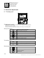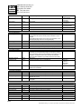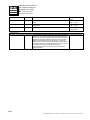
1
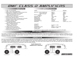
Service Manual
ControlMaster Plus Travel (CMPT)
Adjustable Frequency Drive
Service Manual
R&M Materials Handling, Inc.
4501 Gateway Boulevard
Springfield, Ohio 45502
% : (937) 328-5100
FAX: (937) 325-5319
EN R_(EN)
I
Read the instructions supplied with the hoist before installation and commissioning.
F Keep the instructions in a safe place for future reference.
Table of content
1 General ............................................................ 3
1.1 Technical data ............................................. 3
1.2 Type mark coding ........................................ 4
1.3 Basic description ......................................... 4
1.4 Main components ........................................ 5
1.5 Functional description ................................. 5
1.6 Control methods .......................................... 6
2.3 Test run ..................................................... 10
2.4 After the test run........................................ 10
3 Service........................................................... 11
4 Troubleshooting........................................... 12
4.1 Inverter fault codes.................................... 12
5 Drawings ....................................................... 16
5.1 Description of terminals............................. 16
1.6.1
1.6.2
1.6.3
5.1.1
5.1.2
Description of the control methods, EP.......... 7
Description of the control methods, EP3........ 7
Description of the control methods, MS ......... 8
1.7 Mechanical brake control ............................ 8
2 Start-up procedure......................................... 9
2.1 Visual checks............................................... 9
2.2 Checks before the first test run ................... 9
Terminal in 002-011F .................................. 16
Terminal in 015F......................................... 18
6 Parameter adjustments............................... 19
6.1 The display panel ...................................... 19
6.2 Programming principles ............................ 20
7 Parameter descriptions............................... 21
2/25
R&M Materials Handling, Inc. reserves the right to alter or amend the above information without notice.
R&M Materials Handling, Inc.
4501 Gateway Boulevard
Springfield, Ohio 45502
% : (937) 328-5100
FAX: (937) 325-5319
1 General
I
CAUTION
Before starting, carefully read these instructions and this table.
Verify that all connections are according to the electrical drawings.
Verify that the motor supply is connected correctly. An improper connection will destroy the inverter.
Verify that the internal voltage selections of the device are correct.
Check that the device cover is properly installed and all ventilation holes are clear and uncovered.
Check that the hot air coming from brake resistors does not cause any danger.
High voltages are present in this device. Do not make any inspections until the power supply has
been disconnected at the main switch. Before opening the device cover, wait at least 5 minutes after
the display lamps turn off.
An insulation resistance test, using a megger, requires special precautions.
Do not make any measurements inside the device when it is connected to the main supply.
Do not touch the IC-circuits on the circuit boards. Static voltage discharge may destroy the
components.
It is forbidden to use radiophones and portable phones near this device with the enclosure doors
open.
All the doors and covers must be closed during crane operation.
•
•
•
•
•
•
•
•
•
•
•
•
1.1
Technical data
Power class
Power (kVA) at 400V
Output current In (A)
Max. current 1min (A)
Overload ability
Max. output voltage
Supply
Supply voltage
Allowable voltage fluctuation
Nominal supply frequency
Signal input levels
Digital controls
Encoder feedback
Control features
Control method
Frequency control range
Frequency command
Limit switch functions
Speed control range
Speed accuracy
Extended speed range
Braking torque
Protections
Motor overload protection
Overload protection
Undervoltage / blown fuse
Overvoltage protection
002F
003F
004F
005F
4.5
5.5
7
9
6.5
8
10
13
10
12
15
20
1.5 x In , 1min/10min / 2.5 x In , 2s/20s (<50% speed)
Equal to supply voltage
007F
13
18
27
011F
17
24
36
015F
22
32
48
F-series 380-500VAC
+/- 10%
50/60Hz +/- 5%
S1, S2, DIA3, DIA4, DIA5, DID1, DID2, DID3, DID4, DID5: 42 … 240VAC; 15mA
EA+/- and EB+/-; 0/24V; 3kΩ; floating differential inputs
Open loop vector control
0 ... 120Hz
Motor potentiometer or 2-4-step controller
Slowdown and stop limit inputs for both directions
s N ... 100% (s N= motor nominal slip)
1% of nominal speed at speed range 10 ... 100%
1/3 of motor nominal slip at speed below 10%
100 ... 200%
125%
Thermistor based temperature measurement
Fault is detected if the current momentarily exceeds 280% of rated current
Fault is detected if DC voltage drops below 65% of rectified supply voltage
Fault is detected if DC voltage exceeds 911V
3/25
R&M Materials Handling, Inc. reserves the right to alter or amend the above information without notice.
R&M Materials Handling, Inc.
4501 Gateway Boulevard
Springfield, Ohio 45502
% : (937) 328-5100
FAX: (937) 325-5319
Momentary power loss
Inverter overtemperature
Mechanical brake
Braking transistor
Ground fault
Ambient conditions
Ambient temperature
Storage temperature
Humidity
Altitude
Immediate fault stop
Temperature sensor on the heat sink
Circuit breaker
Electronic supervision
Provided by electronic circuitry
-10°C ... +55°C (14°F ... 131°F) for ED≤60%
-40°C ... +60°C (-31°F ... 140°F) dry
<95%RH (no condensation)
Maximum 1000m at In. Above 1000m: In reduces 1% per each 100m.
Above 3000m: consult factory.
Operation: maximum displacement amplitude 3mm at 2-9Hz.
Maximum acceleration amplitude 0.5g (5m/s²) at 9-200Hz
Confirms to LV and EMC directives.
Vibration
1.2
Type mark coding
The Adjustable Frequency Drive can be summarized as a "crane traveling motor control system, which
controls the speed by changing the frequency of supply voltage of a squirrel cage motor". A stepless
speed adjustment can be achieved by this method.
Type marking is shown below.
D2T
D2T
007
F
V
50
Device name
Power rating class
002 – 015
Supply voltage
F
380 - 500VAC, 50/60Hz
Control voltage
Y
42VAC, 50/60Hz
P
48VAC, 50/60Hz
T
115VAC, 50/60Hz
V
230VAC, 50/60Hz
Revision code
The latest revision may differ
F
V
50
1.3
007
Basic description
The Adjustable Frequency Drive has many advantages and offers many new features, when compared to
other inverter-based systems, which might be used in crane applications.
Inverter
Crane user interface
Brake control
Electrical Braking
Control methods
The inverter in the Adjustable Frequency Drive is a crane inverter. The specific crane features for the
inverter hardware and the special software are achieved by combining the experience and know -how of
crane applications with the latest technology. The inverter uses vector calculation for several different
motor control modes.
The Adjustable Frequency Drive has exactly the same interface with pre-designed locations for all typical
crane functions. The main part of this interface is carried out by a terminal strip, which has separated
sections for signals with main, control and electronics voltage levels.
The Adjustable Frequency Drive includes the brake contactor and the full/half-wave rectifier for brakes.
The Adjustable Frequency Drive includes the braking transistor, which is dimensioned for every crane
application. For resistor braking, the Adjustable Frequency Drive includes a braking resistor.
The Adjustable Frequency Drive can be controlled by the electronic potentiometer control with 2-step
pushbuttons and by the multistep control with 2-4-step controllers. Both these control methods are
4/25
R&M Materials Handling, Inc. reserves the right to alter or amend the above information without notice.
R&M Materials Handling, Inc.
4501 Gateway Boulevard
Springfield, Ohio 45502
% : (937) 328-5100
FAX: (937) 325-5319
Limit switch functions
Protections
1.4
available with ev ery Adjustable Frequency Drive.
The Adjustable Frequency Drive has built-in slowdown and stop limit switch functions for both running
directions.
The Adjustable Frequency Drive includes a motor thermal protection, which is based on motor temperature
measurement by thermistors placed in motor windings. Other protections that may be included Adjustable
Frequency Driveare shown in the technical data.
Main components
The main components are:
A1
F7
K7
G1
G1
Inverter
Circuit breaker
Brake contactor
Brake control unit REC12
Brake control unit ESD141
002-011
015
The most important external components are:
R1
M1
Y1
B6
1.5
Braking resistor unit
Traveling motor
Mechanical brake
Thermal sensor for motor protection
Control devices (switches, pushbuttons etc.)
Limit switches
Functional description
Operation when power is switched on
• The contacts of the limit switches -S11, S12, S21 and S22 and the Emergency Stop button-ES are
normally closed.
• The control voltage is supplied to terminal X1:37. The main voltage is connected to inverter power
supply and the inverter powers up. If the control voltage is connected to RDY-signal and the fault
circuit is OK, inverter is ready to operate in about 1-2 seconds.
• If either of the direction signals-S1 or S2 is on, the display shows F52 and driving can begin only after
the direction signals have been off for a while.
Normal operation
• For the description of the speed reference setting see chapters "Control methods" and "Parameter
Descriptions".
• Running starts when switch-S1 (S2) closes. Closing contact ROB2 on inverter-A1 energizes brake
contactor-K7, which opens the brake. The Adjustable Frequency Drive accelerates according to the
acceleration ramp setting to the selected speed.
• When switch-S1 (S2) opens, the Adjustable Frequency Drive stops according to the deceleration
ramp setting and the brake closes.
• Braking resistor unit-R1 dissipates the regenerated energy during deceleration. The power supply to
R1 is controlled by A1. If the braking resistor fan(s) are included in the Adjustable Frequency Drive,
the cooling device will operate when power is supplied to the braking resistors. The cooling continues
for about 4-5 minutes after the occurrence of electrical braking. This is to ensure that the temperature
of the resistors stays below 150°C (302°F).
Other features
5/25
R&M Materials Handling, Inc. reserves the right to alter or amend the above information without notice.
R&M Materials Handling, Inc.
4501 Gateway Boulevard
Springfield, Ohio 45502
% : (937) 328-5100
FAX: (937) 325-5319
•
•
•
•
•
By opening the slowdown limit switches-S11 and S21, the maximum speed can be limited. The
slowdown speed is adjustable by parameter.
If contact RDY opens for any reason, operation of the inverter is stopped.
The thermistor relay function is used when needed.
When the stop limit switch, S12 or S22 opens, K7 de-energizes and the mechanical brake stops the
motion.
The extended speed range ESR can be used, if the signal FWE (field weakening enabled) is turned
on.
1.6
Control methods
There are three different control methods (command modes) available:
1
EP2
2
EP3
3
MS
Electronic motor potentiometer function.
Stepless control using a 2-step pushbutton controller.
Electronic motor potentiometer function.
Stepless control using a 3-step controller.
Multistep control (4 steps)
The control mode is selected by parameter P2.1.4. The parameters assign digital inputs S1, S2, OK,
DIA3-DIA5 and DID1-DID5. It is not possible to change the functions of the inputs individually. The input
assignment according to the selected mode is explained in the following table.
Control mode
EP
EP3
MS
Parameter P2.1.4
1
2
3
Signal
Terminal
S1
X1:8
S1
S1
S1
S2
X1:9
S2
S2
S2
OK
X1:7
OK
OK
OK
DIA3
X1:10
AP
AP
MS2
DIA4
X1:11
Not used
HOLD
MS3
DIA5
X1:12
Not used
not used
MS4
DID1
X1:38
FWE
FWE
FWE
DID2
X1:39
S11
S11
S11
DID3
X1:40
S21
S21
S21
DID4
X1:41
S12
S12
S12
DID5
X1:42
S22
S22
S22
Desired speed levels for multi-step control mode are selected with following parameters
Speed
Parameter
Input
Speed 1
P2.2.8. / P2.2.9.
S1/ S2
Speed 2
P2.1.7.
MS 2
Speed 3
P2.1.8.
MS 3
Speed 4
P2.1.9.
MS 4
6/25
R&M Materials Handling, Inc. reserves the right to alter or amend the above information without notice.
R&M Materials Handling, Inc.
4501 Gateway Boulevard
Springfield, Ohio 45502
% : (937) 328-5100
FAX: (937) 325-5319
1.6.1 Description of the control methods, EP2
c_coep2a
0. Decelerate
1. Maintain speed
2. Accelerate
A. Pushbutton position
B. Speed
EP2-control uses a 2-step pushbutton. The operation is as follows:
-
Rest position means standstill (0-position)
During run, rest position means deceleration
Step one (switch S1 or S2) means hold speed
When starting, step one means acceleration up to the minimum speed
Step two (switch AP) means acceleration (up to the maximum speed if desired)
At the maximum speed step two means hold speed, because the maximum speed cannot be exceeded
1.6.2 Description of the control methods, EP3
c_coep3a
0. Decelerate
1. Minimum speed
2. Maintain speed
3. Accelerate
A. Pushbutton position
B. Speed
EP3-control uses a 3-step controller. The operation is as follows:
-
Rest position means standstill (0-position)
Step one (switch S1 or S2) is the minimum speed command
Step two (EP hold command) means hold speed
Step three (switch AP) means acceleration (up to the maximum speed if desired)
When releasing the controller, step one means deceleration down to the minimum speed
7/25
R&M Materials Handling, Inc. reserves the right to alter or amend the above information without notice.
R&M Materials Handling, Inc.
4501 Gateway Boulevard
Springfield, Ohio 45502
% : (937) 328-5100
FAX: (937) 325-5319
1.6.3 Description of the control methods, MS
c_coms4a
A. Pushbutton position
B. Speed
MS-control uses a 2-step pushbutton, or 3, 4-step controller. The operation is as follows:
-
Each step has its own frequency
Frequencies are freely selectable
When the pushbutton/controller is set to a certain step, the speed changes to equal value
1.7
Mechanical brake control
The Adjustable Frequency Drive includes a brake contactor to control the electromechanical brake. The
brake operates on DC-voltage. When power is removed to the brake, a spring force closes the brake.
The brake is controlled to remain closed until the motor first generates enough starting torque and then
the brake is opened. The same applies for stopping;, the motor still generates torque while the brake is
being closed. During a direction change, the brake is kept open all the time. After the run command is
switched off, the Adjustable Frequency Drive decelerates the motor to a stop according to the preset
deceleration time. The brake is used as a holding brake, and this way, wear on the brake is minimized.
However, if a failure occurs or the Emergency Stop button is pushed, the brake closes immediately,
stopping the motor and the load.
Models 002F-005F use a REC12 brake control unit, which is a line voltage, half-wave rectifier. The halfwave rectifier reduces losses and is enough to open the brake. A contactor switches the line voltage on
and off.
Models 007F-015F use an ESD141 brake control unit, which is a line voltage, full/half-wave rectifier. Fullwave rectification is used to open the brake quickly. Then, the rectifier changes over to half-wave, which
reduces losses, but is enough to hold the brake open. A contactor switches the line voltage on and off.
The same contactor also disconnects the DC-voltage directly from the brake coil, which assures that the
brake closes fast.
8/25
R&M Materials Handling, Inc. reserves the right to alter or amend the above information without notice.
R&M Materials Handling, Inc.
4501 Gateway Boulevard
Springfield, Ohio 45502
% : (937) 328-5100
FAX: (937) 325-5319
2 Start-up procedure
If any problems or malfunctions occur during the start-up, refer to the Chapter “Troubleshooting”, to find
out the reason. All problems must be solved before continuing. For more information, contact craneservice personnel.
I
Warning! High voltages inside the device. Wait for at least five minutes after the supply
voltage has been switched off before servicing. Display in operating condition (lights on)
indicates a dangerous voltage on the DC-bus. When the display turns off, the DC-bus
voltage is about 100V. Note also that there is a dangerous voltage in the braking resistor
when the DC-bus is charged.
F Do
not connect any voltage to the output terminals (U, V, W). Otherwise, the inverter will be
damaged.
F The
overload protection protects both the supply and the motor cables. The fuses of the supply
provide short circuit protection.
2.1
-
Visual checks
Check the condition of cubicles.
Check that the Adjustable Frequency Drive serial number is the same as in delivery documents.
Check the cabling/wiring to the motor, brake, and thermistors.
Check the motor type.
Check the wire terminations in the motor connection box
Check the wire connections for motor, thermistors and brake wear.
Disconnect motor leads (U, V, W) and brake wires to prevent damage to the inverter. Measure isolation
resistance of brake coil and motor windings (each phase to ground).
Re-connect motor leads and brake wires.
Check the braking resistor.
Terminals, X1:21-27 and X1:51-57 are for electronics level signals.
Normally only shielded wires are connected to these terminals. Check that no control or line-voltage level wires
are connected there.
2.2
Checks before the first test run
I
-
Warning! High voltages inside Adjustable Frequency Drive.
Check the power supply voltage (nominal voltage +/- 10%).
Check the control voltage (nominal voltage +/- 10%).
Make sure that the run commands are off (pushbuttons / controller (master switch) at zero position).
Turn on the power from the main switch and the control voltage switch.
Within about 1 second, the control panel should display "AC on", and then in about 1 second the display
changes to motor output frequency "0.00" and the green READY status indicator turns on.
In a fault situation the red FAULT status indicator blinks and the display shows a fault code instead of
frequency.
Check that the green RUN status indicator is off.
Check that the external connections and the selected input set, P 2.1.4. are according to application.
Parameters are properly set after the factory tests and adjustments are not needed except for the parameters
that depend on the crane application. Write down to the parameter list all the values that have been changed
and at the end save parameters to display file 2.
9/25
R&M Materials Handling, Inc. reserves the right to alter or amend the above information without notice.
R&M Materials Handling, Inc.
4501 Gateway Boulevard
Springfield, Ohio 45502
% : (937) 328-5100
FAX: (937) 325-5319
2.3
-
-
Test run
Make sure that the movement will not cause any danger to the environment or to the crane itself. Avoid driving
close to the limit areas.
Check limit switches manually if possible.
Check the run commands on display panel matches the traveling direction. The arrow rotates clockwise if S1
(right/forward) is applied and counter-clockwise if S2 (left/backward) is applied.
Drive forward at minimum speed for 5 to 10 seconds. Accelerate to full speed. Run 5 to 10 seconds. Stop.
Repeat the same in the reverse direction. Check the frequency display to make sure that the frequency
changes through the whole operational frequency range from minimum to nominal speed.
Check the motor operation (acceleration, deceleration and braking): accelerate to full speed forward, change to
full speed backward and full speed forward again and stop.
Check the limit switch functions: drive slowly to limit switches and check the slowdown and stop limit switch
operations. Re-check using full speed. Repeat the same check for the other direction.
If the optional ESR is used, check the maximum frequency as stated in the testing table.
2.4
-
After the test run
Record all parameter value changes in the parameter list.
Make sure all remarks and setting values are recorded.
It is recommended to store the parameter settings in the memory of the display panel, file 2.
10/25
R&M Materials Handling, Inc. reserves the right to alter or amend the above information without notice.
R&M Materials Handling, Inc.
4501 Gateway Boulevard
Springfield, Ohio 45502
% : (937) 328-5100
FAX: (937) 325-5319
3 Service
The Adjustable Frequency Drive does not require regular maintenance. The following actions are
recommended:
•
•
•
•
•
Check inverter fault history
Find out the reasons of any possible faults
Clear the fault history
Clean the heat sink on the inverter
Prevent the dust to spread inside cubicles
Lock the fans before blowing compressed air
Check that there are no abnormal noises coming from the cooling fans
Tighten all screws and connectors
Clean the dust from PC-boards
F The
parameters are saved in an EEPROM, which keeps the parameters in memory after power off
without any battery backup.
11/25
R&M Materials Handling, Inc. reserves the right to alter or amend the above information without notice.
R&M Materials Handling, Inc.
4501 Gateway Boulevard
Springfield, Ohio 45502
% : (937) 328-5100
FAX: (937) 325-5319
4 Troubleshooting
I
Warning! High voltages inside the frequency converter. Wait for at least five minutes after
the supply voltage has been switched off before servicing. Display in operating condition
(lights on) indicates a dangerous voltage on the DC-bus. When the display turns off, the DCbus voltage is about 100V. Note that there is a dangerously high voltage in the braking
resistor when the DC-bus is charged.
This chapter describes how to troubleshoot inverter faults. The purpose is to find out which components
are damaged and how to replace or restore them for proper operation. Advice is also given to find the
possible external failures that could affect the Adjustable Frequency Drive function.
4.1
Inverter fault codes
If any one of the following faults occurs, the inverter displays the fault code and the operation of the
crane/hoist is stopped. If several faults occur one after another, the latest one is displayed, while the
others are stored to the fault history page on the inverter. The Adjustable Frequency Drive includes an
automatic fault reset operation; the fault code stays on the display until the fault is removed and the
controller is released back to 0-position. Some of the fault codes require to switch the power off before
run is possible.
When the fault supervision trips, the FAULT indicator turns on and the blinking fault code “F xx“ (xx =
fault number) appears on the display. The faults are stored to the fault history; from there they can be
seen if necessary.
Fault
code
Fault
Possible cause
Checking
F1
Overcurrent
Inverter has measured too high current (over
4*In) in the motor output:
Reset: switch power off and restart after the
lamps of display are off.
Check:
sudden heavy load increase
short circuit in the motor or cable
not suitable motor
wrong motor parameters
F2
Overvoltage
DC-bus voltage has exceeded 135% maximum
level, 911Vdc (F-series), 1258 Vdc (K-series)
supply voltage raised >1.35 x Un
(high overvoltage spikes at
mains)
deceleration time is too short
motor type and power rating
parameters
motor cables
motor insulation
brake operation
motor loading
Check:
adjust the deceleration time
longer
measure main supply voltage
level and wave form while not
driving
motor insulation
motor cable insulation (phaseground, phase-phase)
braking resistor cable
braking resistor type and
resistance
braking chopper operation
12/25
R&M Materials Handling, Inc. reserves the right to alter or amend the above information without notice.
R&M Materials Handling, Inc.
4501 Gateway Boulevard
Springfield, Ohio 45502
% : (937) 328-5100
FAX: (937) 325-5319
F3
Earth fault
Current measurement has sensed unbalance in
motor phase currents. Supervision level is 5% of
inverter nominal current
not symmetric load
insulation failure in the motor or
the cables
F4
F5
F7
motor insulation
motor cable insulation (phaseground, phase-phase)
Unknown
Charging switch
Charging switch is open when START command
becomes active
interference fault
component failure
F6
Reset: switch power off and res tart after the
lamps of display are off.
Check:
Emergency Stop
Saturation trip
Either the ES or RDY-signal has
been tripped during
Very high overload or defective component
Reset: sw itch power off and restart after the
lamps of display are off.
Check:
control unit and power unit
connections
charging resistors
If the fault comes again, change
the control unit.
Check:
ES and RDY external
connections
brake operation
Reset: switch power off and restart after the
lamps of display are off.
Check:
motor and motor cable insulation
measure main circuit diodes and
IGBT transistors
If the fault comes again, change
the power unit.
F8
F9
Unknown
Undervoltage
DC-bus voltage has dropped below 65% of
rectified supply voltage
main supply voltage <0.65 x Un
inverter fault can also cause an
undervoltage trip
external fault during run may
cause an undervoltage trip
F 10
F 11
F 12
In case of temporary supply voltage break, reset
the fault and start again. Check mains input.
If mains supply is correct, an
internal failure has occurred.
Contact crane service.
Input line
supervision
One input line phase is missing or
supply voltage parameter is wrong
Check:
Output phase
supervision
Current supervision has sensed that one of the
motor phases has no current
Check:
Braking chopper
supervision
During run braking chopper have short test pulse
every 1s period. Test pulse measures transistor
collector voltage. Fault appears if
Reset: switch power off and restart after the
lamps of display are off.
Check:
braking resistor is broken
braking chopper is broken
braking resistor is not installed
supply voltage
main connection.
motor cable connections
measure motor phase currents
and compare to display value
braking resistor and cable
resistance and insulation
resistance
measure braking transistor IGBT
and free wheeling diodes
If resistor is OK, then the
13/25
R&M Materials Handling, Inc. reserves the right to alter or amend the above information without notice.
R&M Materials Handling, Inc.
4501 Gateway Boulevard
Springfield, Ohio 45502
% : (937) 328-5100
FAX: (937) 325-5319
chopper is broken
Contact service
F 13
F 14
F 22
F 23
F 24
F 25
Inverter
undertemperature
Temperature of heat sink is below acceptable
operating level (-10°C /14°F)
Check
Inverter
overtemperature
Temperature of heat sink is over acceptable
operating level
+80°C (176°F).
Overtemperature warning is issued when the
heat sink temperature exceeds +75°C (167°F)
Check:
EEPROM
checksum fault
Parameter restoring error
After power is off, the inverter will automatically
load factory-default parameter settings. Drive
does not work properly nor enable driving after
this fault.
Check:
Changed data
warning
Microprocessor
watchdog-fault
F 26
F 32
Power Unit Fault
F 33
F 34
Memory fault
F 35
F 36
F 37
Fan cooling fault
interference fault
component failure (control unit)
faulty supply voltage
programming
Changes may have occurred in the different
counter data due to mains interruption
interference fault
component failure (control unit)
Cooling fan of the frequency converter do not
work, when ON command has been given
ambient temperature
cubicle heating
ambient temperature
fan operation
cooling air flow through heat sink
heat sink is not dusty
all parameter settings.
If the fault comes again, contact
service.
No special actions required. Take a critical
attitude to the counter data.
Reset: switch power off and restart after the
lamps of display are off.
If the fault comes again, contact service.
If the fault comes again, contact
service.
Communication
fault
Application fault
Run-time exception in the application program
Control Unit
Faulty Control Unit.
Device changed
Reset the fault
Contact service.
F 38
Device added
F 39
F 40
F 41
Device removed
Option board changed. Different power rating of
drive
Option board added. Drive of different power
rating added
Option board removed. Drive removed
Device unknown
Unknown option board or drive.
Check board and drive type.
IGBT temperature
Too high temperature in IGBT transistors.
Check:
long duration overload
lowered cooling
high environment temperature
F 48
F 50
Reset the fault
Reset the fault
motor loading
brake operation
inverter heatsink
inverter cooling fan operation
environment temperature
EEprom CRC-fault
Reference value
fault
Analog input signal is out of selected range 1-9V
or 2-10V
control cable is broken
signal source has failed
F 51
Stop limit
Stop limit has tripped
F 52
Panel
communication
Poor connection between inverter and display
panel
Check
reference cable
reference source
Reset: keep controller at zero >500ms.
Ensure that fault disappears after leaving the
stop limit.
Check the panel connection and optional cable.
14/25
R&M Materials Handling, Inc. reserves the right to alter or amend the above information without notice.
R&M Materials Handling, Inc.
4501 Gateway Boulevard
Springfield, Ohio 45502
% : (937) 328-5100
FAX: (937) 325-5319
F 53
F 54
F 55
F 56
F 57
F 60
F 61
F 62
F 63
F 64
F 65
F 66
F 67
F 70
error
Profibus
communication
error
Profibus control
fault
Board Fault
Not used in Adjustable Frequency Drive
Contact crane service.
Not used in Adjustable Frequency Drive
Contact crane service.
Some of following board is
missing:
A=Basic I/O board
B=Thermistor board
D=Expansion board
Generator side
current limit
Too short deceleration time
Thermistor fault
Expansion board thermistor input has detected
motor overtemperature
Check board slots A, B and D
Check:
generator side current limit
deceleration time
encoder pulses
current limit setting
Check:
motor cooling and loading
thermistor connection. If
expansion board thermistor
input is not used, it should be
jumpered
parameters
the brake operation
Contact service
Parameter fault
Inverter has lost parameters
Overspeed Fault
Not used in Adjustable Frequency Drive
Contact crane service.
Speed Difference
Fault
Stall Supervision
Fault
SSU Relay Test
Fault
SSU Watchdog
Not used in Adjustable Frequency Drive
Contact crane service.
Not used in Adjustable Frequency Drive
Contact crane service.
Not used in Adjustable Frequency Drive
Contact crane service.
Not used in Adjustable Frequency Drive
Contact crane service.
SSU Overspeed
Limit
Encoder channel B
Not used in Adjustable Frequency Drive
Contact crane service.
Not used in Adjustable Frequency Drive
Contact crane service.
Multicare Fault
Not used in Adjustable Frequency Drive
Check:
other drive fault history
brake relay control delay
settings
F 71
Brake Control Fault
Not used in Adjustable Frequency Drive
Check
Ain2 wiring
Check hoist control unit settings
F 72
Brake Feedback
Fault
Brake is opening or closing in wrong time
Check:
brake operation
Check brake relay (ROB2) and
brake contactor (K7/K71)
operation
15/25
R&M Materials Handling, Inc. reserves the right to alter or amend the above information without notice.
R&M Materials Handling, Inc.
4501 Gateway Boulevard
Springfield, Ohio 45502
% : (937) 328-5100
FAX: (937) 325-5319
5 Drawings
5.1
Description of terminals
5.1.1 Terminal in 002-011F
No
Name
Description, signal level
PE
L1
L1
Power supply, phase 1
L2
L2
Power supply, phase 2
L3
L3
Power supply, phase 3
U
U
Motor output, phase 1
V
V
Motor output, phase 2
W
W
Motor output, phase 3
B+
R+
Braking resistor
R-
R-
Braking resistor
No Name
Description, signal level
No Name
Description, signal level
1
BL1
AC brake supply, phase 1
31
BD1
DC brake supply 1
2
BL2
AC brake supply, phase 2
32
BD2
DC brake supply 2
3
BL3
AC brake supply, phase 3
33
T1
Thermistor input
4
T12
Reserved for thermistors connections
34
T2
Thermistor input
5
OLE
External control voltage, 48/115/230Vac
35
ONE
Neutral of external control voltage OLE
6
OLE
External control voltage, 48/115/230Vac
36
ONE
Neutral of external control voltage OLE
7
RDY
Stop with brake
37
ES
External Stop
8
S1
Direction 1 run command
38
DID1
Free input
9
S2
Direction 2 run command
39
DID2 (S11)
Slowdown signal, direction 1
10
DIA3
Multi Function Input
40
DID3 (S21)
Slowdown signal, direction 2
11
DIA4
Free input
41
DID4 (S12)
Stop limit signal, direction 1
12
DIA5
Free input
42
DID5 (S22)
Stop limit signal, direction 2
13
43
14
44
15
K7-A1
Coil of brake contactor K7
45
ROB1-21
Free NC contact of ROB1
16
ROB1-22
Free C contact of ROB1
46
ROB1-23
Free NO contact of ROB1
17
ROD1-28
Free NO-contact of relay ROD1
47
ROD1-29
Free NO-contact of relay ROD1
18
K7-153
Free NO-contact of K7
48
K7-154
Free NO-contact of K7
19
K7-163
Free NO-contact of K7
49
K7-164
Free NO-contact of K1
20
K71-13
Free NO-contact of K71
50
K71-14
Free NO-contact of K71
PE
16/25
R&M Materials Handling, Inc. reserves the right to alter or amend the above information without notice.
R&M Materials Handling, Inc.
4501 Gateway Boulevard
Springfield, Ohio 45502
% : (937) 328-5100
FAX: (937) 325-5319
21
51
22
52
23
53
24
54
25
55
26
56
27
57
PE
17/25
R&M Materials Handling, Inc. reserves the right to alter or amend the above information without notice.
R&M Materials Handling, Inc.
4501 Gateway Boulevard
Springfield, Ohio 45502
% : (937) 328-5100
FAX: (937) 325-5319
5.1.2 Terminal in 015F
No Name
Description, signal level
PE
91
L11
Auxiliary power supply, phase 1
92
L12
Auxiliary power supply, phase 2
93
L13
Auxiliary power supply, phase 3
No Name
Description, signal level
No Name
Description, signal level
1
BL1
AC brake supply, phase 1
31
BD1
DC brake supply 1
2
BL2
AC brake supply, phase 2
32
BD2
DC brake supply 2
3
BL3
AC brake supply, phase 3
33
T1
Thermistor input
4
T12
Reserved for thermistors connections
34
T2
Thermistor input
5
OLE
External control voltage, 48/115/230Vac
35
ONE
Neutral of external control voltage OLE
6
OLE
External control voltage, 48/115/230Vac
36
ONE
Neutral of external control voltage OLE
7
RDY
Stop with brake
37
ES
External Stop
8
S1
Direction 1 run command
38
DID1
Free input
9
S2
Direction 2 run command
39
DID2 (S11)
Slowdown signal, direction 1
10
DIA3
Multi Function Input
40
DID3 (S21)
Slowdown signal, direction 2
11
DIA4
Free input
41
DID4 (S12)
Stop limit signal, direction 1
12
DIA5
Free input
42
DID5 (S22)
Stop limit signal, direction 2
13
43
14
44
15
K7-A1
Coil of brake contactor K7
45
ROB1-21
Free NC contact of ROB1
16
ROB1-22
Free C contact of ROB1
46
ROB1-23
Free NO contact of ROB1
17
ROD1-28
Free NO-contact of relay ROD1
47
ROD1-29
Free NO-contact of relay ROD1
18
K7-153
Free NO-contact of K7
48
K7-154
Free NO-contact of K7
19
K7-163
Free NO-contact of K7
49
K7-164
Free NO-contact of K1
20
K71-13
Free NO-contact of K71
50
K71-14
Free NO-contact of K71
PE
21
51
22
52
23
53
24
54
25
55
26
56
27
57
PE
18/25
R&M Materials Handling, Inc. reserves the right to alter or amend the above information without notice.
R&M Materials Handling, Inc.
4501 Gateway Boulevard
Springfield, Ohio 45502
% : (937) 328-5100
FAX: (937) 325-5319
6 Parameter adjustments
6.1
The display panel
RUN
STOP READY ALARM FAULT
V 4.17.
I/O termKeypad
Motor Speed
2002 rpm
ready run fault
START
reset
STOP
enter
select
The display panel is used for:
-
Displaying the drive identification, electrical values, operating or fault parameters
Altering the parameter settings
Saving and restoring the parameter settings in the memory of the display panel
Meaning of the displays:
RUN
Motor is running, blinks when ramping down.
Indicates the direction of motor rotation.
STOP
Indicates that motor is not running.
I/O term
Lights up when power is on. In case of a trip, the symbol will not light
up.
Indicates that the drive is running outside of certain limit.
Drive was stopped due to unsafe operating conditions
I/O-terminals are the selected control place
Keypad
Keypad is the selected control place
READY
ALARM
FAULT
The signaling LED’s
“ready”
“run”
“fault”
Lights up when power is on. In case of a trip, the symbol will not light
up.
Motor is running, blinks when ramping down.
Indicates that unsafe operating conditions were encountered due to
which
Button description
Reset active faults
reset
Switch between two latest displays
select
enter
Confirmation of selections
Fault history reset
19/25
R&M Materials Handling, Inc. reserves the right to alter or amend the above information without notice.
R&M Materials Handling, Inc.
4501 Gateway Boulevard
Springfield, Ohio 45502
% : (937) 328-5100
FAX: (937) 325-5319
Browse the main menu and the pages of submenus
Edit values
START
6.2
Move in menu
Move cursor
Exit and enter edit mode
Start button
Starts motor if the keypad is the active control place
Programming principles
To program the Adjustable Frequency Drive, change the parameter settings from the display panel.
Moving from menu to menu is done from the browser buttons of the display panel and entering into a
menu is done from the
button.
The parameter values can be edited by entering the Parameter Menu from the Main menu when the
location indication M2 is visible on the first line of the display.
Push the
button once to move into the Parameter Group Menu. Locate the parameter group desired
by using the
and
buttons. Push
button again to enter the group and its parameters. Use again
the
and
buttons to find the parameter you want to edit. Pushing the
button takes you to the edit
mode. As a sign of this, the parameter value starts to blink. You can now change the value in two
different manners:
1. Set the new desired value with
and
buttons and confirm the change with
button.Consequently, the blinking stops and the new value is at display.
2. Bush the
button once again. Now you will be able to edit the value digit by digit. Confirm the
change with
.
The value will not change unless the
button is pushed. Pressing the
button takes you
back to the previous menu.
enter
enter
enter
I
I
WARNING! Changing parameter settings during running can cause a hazardous situation.
Parameter settings must not be changed during running.
WARNING! Driving via display can cause a hazardous situation. Panel control must not be
used.
20/25
R&M Materials Handling, Inc. reserves the right to alter or amend the above information without notice.
R&M Materials Handling, Inc.
4501 Gateway Boulevard
Springfield, Ohio 45502
% : (937) 328-5100
FAX: (937) 325-5319
7 Parameter descriptions
Label
G2.1 General Parameters
Password
Supply Voltage
Device
Input Set
Analog Input Sel
Slow speed freq
Code
Function/Description
Adjustment range
P2.1.1
V2.1.2
V2.1.3
P2.1.4
P2.1.5
P2.1.6
Password
Power unit nominal voltage
Device
Input Set selection, see chapter “Control methods”
Analog input selection, see chapter “Mechanical brake control”
Speed when one of slow down limit switches (S11/S21) is open
0-65535
Multistep 2 freq
Multistep 3 freq
P2.1.7
P2.1.8
2nd preset speed. Multistep speed setting.
3rd preset speed. Multistep speed setting.
Min. freq-Max.freq
Min. freq-Max.freq
Multistep 4 freq
P2.1.9
4th preset speed. Multistep speed setting.
Min. freq-Max.freq
Accel Time 1
P2.1.10
1-300
Decel Time 1
P2.1.11
Acceleration ramp is defined from zero to motor nominal frequency
P 2.2.2. Minimum setting is 1s
Deceleration ramp is defined from motor nominal frequency P2.2.2
to zero. Minimum setting is 1s
G2.1.12 Multicare
Test Voltage Min
Test Voltage Max
B2.1.12.1
B2.1.12.2
Not used in Adjustable Frequency Drive
Not used in Adjustable Frequency Drive
Ain 1 Value
P2.1.12.3.
Not used in Adjustable Frequency Drive
Min Value Volt
Max Value Volt
P2.1.12.4.
P2.1.12.5.
Not used in Adjustable Frequency Drive
Not used in Adjustable Frequency Drive
G2.2 Motor Parameters
Motor Nom Volt
P2.2.1
Nominal motor voltage Un from motor rating plate
0 – 750V
Motor Nom freq
P2.2.2
Nominal motor frequency fn from motor rating plate
0 – 250 Hz
Motor Nom Speed
Motor Nom Curr
P2.2.3
P2.2.4
Nominal motor speed nn from motor rating plate
Nominal motor current In from motor rating plate
0 – 6000 rpm
0 – 3000 A
Nom Flux Curr
P2.2.5
Nominal motor magnetizing current Io from motor rating plate
0 – 3000 A
Start Current
Current Limit
P2.2.6
P2.2.7
Current at start, setting must not be changed
Inverter’s max. output current, must not be changed
0 – 2000 A
0 – 3000 A
Min Freq S1
P2.2.8
Minimum frequency forward
0 – Max Freq
Min Freq S2
Max Freq S1
P2.2.9
P2.2.10
Minimum frequency backward
Maximum frequency forward
0 – Max Freq
0 – Max Freq
Max Freq S2
P2.2.11
Maximum frequency backward
0 – Max Freq
Max ESR freq
Drive Selection
P2.2.12
P2.2.13
Maximum frequency when ESR activated
Application selection, setting must not be changed
Max Freq–250 Hz
0 - none
1 - travel
2 – hoisting
Pulse Wheel ppr
P2.2.14
Zero Freq Volt
U/f Mid Volt
P2.2.15
P2.2.16
Pulse wheel pulse number, not used in Adjustable Frequency
Drive
Output voltage at zero frequency
Voltage in the selected middle point
0 - 250 Hz
0 – 3000 V
U/f Mid Freq
P2.2.17
Middle point frequency
0 – 250 Hz
Torque Boost
RS Voltage Stop
P2.2.18
P2.2.19
Torque maximisation, setting must not be changed
Relative value of motor stator impedance voltage drop
0=OFF, 1=ON
0 –512
Stop Function
P2.2.20
Stopping mode selection
0: When the drive command is switched off the motion is stopped
according to the set deceleration ramp.
0-1
Industrial
1-3
0-3
Min. freq-Max.freq
1-300
21/25
R&M Materials Handling, Inc. reserves the right to alter or amend the above information without notice.
R&M Materials Handling, Inc.
4501 Gateway Boulevard
Springfield, Ohio 45502
% : (937) 328-5100
FAX: (937) 325-5319
1: When the drive command is switched off the motor current is cut
off and the mechanical brake stops the motion.
G4. Monitoring
G4.4. Fault Counter
Fault Counter
R4.4.1.
Fault counter value. Fault number
Total Faults
V4.4.2
Total number of all faults
G4.6. Digital Input
S1
S2
V4.6.1.
V4.6.2.
State of digital input S1
State of digital input S2
0=OFF, 1=ON
0=OFF, 1=ON
DIA3
V4.6.3.
State of digital input DIA3
0=OFF, 1=ON
DIA4
DIA5
V4.6.4.
V4.6.5.
State of digital input DIA4
State of digital input DIA5
0=OFF, 1=ON
0=OFF, 1=ON
OK
V4.6.6.
State of digital input OK
0=OFF, 1=ON
DID1
DID2
V4.6.7.
V4.6.8.
State of digital input DID1
State of digital input DID2
0=OFF, 1=ON
0=OFF, 1=ON
DID3
V4.6.9.
State of digital input DID3
0=OFF, 1=ON
DID4
DID5
V4.6.10.
V4.6.11.
State of digital input DID4
State of digital input DID5
0=OFF, 1=ON
0=OFF, 1=ON
Basic Board
V4.6.12.
State of board A inputs, S1,S2,DIA3,DIA4,DIA5
0=OFF, 1=ON
Extension Board
V4.6.13.
State of board D inputs, DID1 – DID5
0=OFF, 1=ON
G4.7. SSU
Overspd Lim 1
Overspd Lim 2
V4.7.1.
V4.7.2.
Value of overspeed limit 1. Not used in D2L.
Value of overspeed limit 2. Not used in D2L.
%
%
Freq Ref
SpeedReg
V4.8.
V4.9.
Frequency reference
Hz
Hz
Distance Counter
V4.10.
m
DC-Link Voltage
Heat Sink Temp
V4.11.
V4.12.
Calculates the distance from slow down limit. Operates within
slowdown area. Not operating if parameter P5.2. value is 0
Measured DC-link voltage
Measured heat sink temperature
Motor Power
V4.13.
Calculated motor power
°C
%
Motor Voltage
Motor Torque
V4.14.
V4.15.
Calculated motor voltage
Calculated actual torque
%
%
Motor Current
V4.16.
Measured motor current
%
Motor Speed
Output Frequency
V4.17.
V4.18.
Calculated motor speed
Output frequency to the motor
rpm
Hz
G5 Panel Control
Panel Control
B5.1.
Must not be used.
0=OFF, 1=ON
Speed Reference
R5.2.
Speed reference for panel control
M6 System Menu
Application
S6.1.
Application
Language
S6.2
Keypad language
S6.3. System settings
Password
S6.3.1
Must not be used
V
22/25
R&M Materials Handling, Inc. reserves the right to alter or amend the above information without notice.
R&M Materials Handling, Inc.
4501 Gateway Boulevard
Springfield, Ohio 45502
% : (937) 328-5100
FAX: (937) 325-5319
Parameter lock
P6.3.2
Prohibit changes to parameters
InternBrake Res
P6.3.3.
Setting must not be changed
Fan Control
P6.3.4.
Fan control
Multmon. page
P6.3.5.
HMI ACK timeout
HMI retry
P6.3.6
P6.3.7.
HMI ACK timeout
HMI retry
S6.4. Keypad settings
Default page
P6.4.1.
Default page to which the display automatically moves as the
Timeout time has expired or as the power is switched on to the
keypad.
If the Default Page value is 0 the function is not activated, i.e. the
last displayed page remains on the keypad display.
Default page/OM
Timeout time
P6.4.2.
P6.4.3.
The time after which the keypad display returns to default page.
Contrast
P6.4.4.
Display contrast.
Backlight time
P6.4.5.
Determines how long the backlight stays before going out.
S6.5. Param Transfer
Up to keypad
S6.5.1
Downfrom keypad
S6.5.2
The parameter transfer function is used when the operator wants
to transfer one or all parameter groups from one drive to another.
All the parameter groups are first uploaded to the keypad, then the
keypad is connected to another drive and then the parameter
groups are dow nloaded to it (or possibly back to the same drive).
see. S6.5.1
Parameter Sets
S6.5.3.
Transfer parameters from / to parameter set
Param BackUp
P6.5.4
If value is “yes”, parameter backup will be done at every power up
without user confirmation
S6.6. Param Comparison
Set 1
S6.6.1.
Actual parameter values are compared to Set 1 parameter values.
Set 2
S6.6.2.
Actual parameter values are compared to Set 2 parameter values.
Factory settings
S6.6.3.
Keypad set
S6.6.4.
Actual parameter values are compared to inverter manufacturer
defaults, do not use
Actual parameter values are compared to parameter values loaded
to keypad.
S6.7. Info
Power unit
Unit voltage
I6.7.1.
I6.7.2.
Manufacturer data
Nominal voltage of the power unit
Software version
I6.7.3.
Control unit software version.
Firmware interf.
I6.7.4.
Application interface version of the software.
S6.7.5. Expanders
A:
State
E6.7.5.1.
E6.7.5.1.1.
Type of expander board at slot A
State of expander board at slot A
Program version
E6.7.5.1.2
Software version of expander board at slot A
Change Enable /
Change Disable
Connected / Not
Connected
0=continous /
1=temperature
0=Change Enable
/1=Change Disable
Store Set 1
Load Set 1
Store Set 2
Load Set 2
Yes / No
NXOPTA6
RUN
23/25
R&M Materials Handling, Inc. reserves the right to alter or amend the above information without notice.
R&M Materials Handling, Inc.
4501 Gateway Boulevard
Springfield, Ohio 45502
% : (937) 328-5100
FAX: (937) 325-5319
B:
E6.7.5.2.
Type of expander board at slot B
NXOPTA3
State
E6.7.5.2.1.
State of expander board at slot B
RUN
Program version
C:
E6.7.5.2.2
E6.7.5.3.
Software version of expander board at slot B
Type of expander board at slot C
No board
State
E6.7.5.3.1.
State of expander board at slot C
RUN
Program version
D:
E6.7.5.3.2
E6.7.5.4.
Software version of expander board at slot C
Type of expander board at slot D
NXOPTB9
State
E6.7.5.4.1.
State of expander board at slot D
RUN
Program version
E:
E6.7.5.4.2
E6.7.5.5.
Software version of expander board at slot D
Type of expander board at slot E
No board
State
E6.7.5.5.1.
State of expander board at slot E
RUN
Program version
E6.7.5.5.2
Software version of expander board at slot E
S6.7.6. Applications
A6.7.6.1. Adjustable Frequency Drive
Application id
D6.7.6.1.1
Application identification number
Version
Firmware interf
Application version number
Firmware interface number
D6.7.6.1.2
D6.7.6.1.3
S6.7.7. Debug
Not used in Adjustable Frequency Drive
S6.8. Counters
MWh counter
C6.8.1.
MWh counter, cannot be reset
Op Day Counter
C6.8.2.
Operation day counter, cannot be reset
Op. hour counter
C6.8.3.
Operation hour counter, cannot be reset
S6.9. Trip counters
MWh Counter
Clr MWh Counter
T6.9.1.
P6.9.2.
MWh counter, can be reset
Clear MWh counter
Op Day Counter
T6.9.3.
Operation day counter, can be reset
Op hour Counter
Clr Optime cntr
T6.9.4.
P6.9.5.
Operation hour counter, can be reset
Clear Operation time counters
M7 Active faults
The memory of active faults can store the maximum of 10 faults in
the order of appearance.
T.1
By pushing the
button you will enter the Fault-time data record
menu indicated by T.1-T.13. In this menu some selected important,
data valid at the time of the fault, are recorded.
Counted operation days
d
T.2
T.3
Counted operation hours
Output frequency
hh:mm:ss
Hz
T.4
Motor current
A
T.5
T.6
Motor voltage
Motor power
V
%
T.7
Motor torque
%
T.8
T.9
DC voltage
Unit temperature
V
T.10
Ready
°C
0=Not Ready
1=Ready
24/25
R&M Materials Handling, Inc. reserves the right to alter or amend the above information without notice.
R&M Materials Handling, Inc.
4501 Gateway Boulevard
Springfield, Ohio 45502
% : (937) 328-5100
FAX: (937) 325-5319
Run
T.11
T.12
T.13
0=Not Running
1=Run
0=Off 1=On
0=No 1=Yes
0=No 1=Yes
0=No 1=Yes
0=Not Zero Speed
1=Zero Speed
Direction
Fault
Warning
At reference
0-speed
M8 Fault history
The fault memory can store a maximum of 30 faults in the order of
appearance. The number of faults currently in the fault history is
shown on the value line of the main page. The order of the faults is
indicated by the location indication in the upper left c orner of the
display. The latest fault carries the indication F8.1, the second
latest F8.2 etc. The Fault-time data record pages are accessible at
each fault. If there are 30 uncleared faults in the memory, the next
occurring fault will erase the oldest from the memory.
Pressing the Enter button for about 2 to 3 seconds resets the
whole fault history.
25/25
R&M Materials Handling, Inc. reserves the right to alter or amend the above information without notice.