1
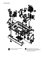
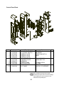
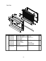
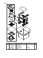
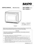
FILE NO.
SERVICE MANUAL
Microwave Oven
EMO-SRT1(NX)
EMO-SRT1(SG)
Model No
Pro.Code No
EMO-SRT1NX 437 517 01
EMO-SRT1SG 437 517 00
Foreword
Read this manual carefully, especially precaution on microwave energy, and follow the procedure strictly,
careless servicing and testing may expose yourself to the microwave energy leakage.
PRECAUTIONS
PRECAUTIONS TO BE OBSERVED BEFORE AND DURING SERVICING TO AVOID POSSIBLE EXPOSURE TO
EXCESSIVE MICROWAVE ENERGY
(a) Do not operate or allow the oven to be operated with the door open.
(b) Make the following safety checks on all ovens to be serviced before activating the magnetron or other
microwave source, and make repairs as necessary:
(1)Interlock operation, (2) proper door closing, (3) seal and sealing surfaces (arcing, wear, and other
damage), (4) damage to or loosening of hinges and latches, (5) evidence of dropping or abuse.
(c) Before turning on microwave power for any service test or inspection within the microwave generating
compartments, check the magnetron, wave guide or transmission line, and cavity for proper alignment,
integrity, and connections.
(d) Any defective or misadjusted components in the interlock, monitor, door seal, and microwave generation
and transmission systems shall be repaired replaced, or adjusted by procedures described in this manual
before the oven is released to the owner.
REFERENCE NO. SM-6410005-00
- TABLE OF CONTENTS Adjustment Procedures ............................................. 1
Specifications ............................................................ 2
Power output Measurement ...................................... 2
Precautions and Repair Service Tips ....................... 2
Circuit Diagram ......................................................... 3
Test Procedures and Troubleshooting............... 4-10
Disassembly Instructions ............................
11-14
Exploded View and Parts List ............................ 15-22
Overall Circuit Diagram................................. 23-25
up and rotated counterclockwise until there is zero
gap between the latch lever and the switch bodies
when the door latch is securely locked.
(4) Make sure the latch interlock switch open before
the interlock monitor switches coses when the door
is opened very slowly, according to “CHECKOUT
PROCEDURE FOR SWITCHES” on page 6.
(5)Make sure the microwave energy leakage is below
the limit of the reguration 5 mW/cm 2when
measured with a detector.
(All service adjustments must be made for minimum microwave energy leakage readings.)
NOTE: If the interlock monitor circuit operates and at
the same time the fuse blows with the door
open, be sure to replace the relay circuit board
, Interlock switch and monitor switch.
CAUTION
MICROWAVE RADIATION
PERSONNEL SHOULD NOT BE EXPOSED TO
THE MICROWAVE ENERGY WHICH MAY RADIATE FROM THE MAGNETRON OR OTHER
MICROWAVE GENERATING DEVICE IF IT IS
IMPROPERLY USED OR CONNECTED. ALL
INPUT AND OUTPUT MICROWAVE CONNECTIONS, WAVEGUIDE, FLANGES, AND GASKETS
MUST BE SECURE. NEVER OPERATE THE
DEVICE WITHOUT A MICROWAVE ENERGY
ABSORBING LOARD ATTACHED. NEVER LOOK
AN OPEN WAVEGUIDE OR ANTENNA WHIL THE
DEVICE IS ENERGIZED.
1. ADJUSTMENT PROCEDURES
TO AVOID POSSIBLE EXPOSURE TO MICROWAVE
ENERGY LEAKAGE, THE FOLLOWING ADJUSTMENTS OF THE INTERLOCK SWITCHES SHOULD
BE MADE ONLY BY AUTHORIZED SERVICE PERSONNEL.
Lever Stopper
A.INTERLOCK SWITCH AND DOOR SENSING
SWITCH ADJUSTMENT(Figure 1)
(1) Loosen 2 screws securing the lever stopper.
(2) Adjust the lever stopper position so that it is pushed
up and rotated counterclockwise until there is zero
gap between the latch and the switch bodies when
the door latch is securely locked.
(3) Tighten the lever stopper screws securely.
(4) Make sure the latch interlock switch and the door
sensing switch open before the interlock monitor
switches coses when the door is opened very
slowly, according to “CHECKOUT PROCEDURE
FOR SWITCHES” on page 7.
(5)Make sure the microwave energy leakage is below
the limit of the reguration5 mW/cm 2when
measured with a detector.
(All service adjustments must be made for minimum microwave energy leakage readings.)
Interlock
monitor switch
Lever
Door sensing
switch
Door Interlock
switch
Screws
B.DOOR INTERLOCK SWITCHES ADJUSTMENT
(Figure 1)
(1) Loosen 2 screws securing the lever stopper.
(2) Adjust the lever stopper position so that it is pushed
Figure 1
- 1 -
2.SPECIFICATIONS
A. SINCE NEARLY 4,000 VOLTS EXISTS IN SOME
CIRCUITS OF THIS MICROWAVE OVEN, REPAIRS SHOULD BE CARRIED OUT WITH
GREAT CARE.
B. TO AVOID POSSIBLE EXPOSURE TO MICROWAVE ENERGY LEAKAGE, THE FOLLOWING
PRECATIONS MUST BE TAKEN BEFORE SERVICING.
(1) Before the power is applied.
(a) Open and close door several times to make
sure the interlock switch, door sensing switch
and interlock monitor switch operate properly.
(Listen for the clicking sound from switches.)
Make sure the interlock monitor switch is
closed after the interlock switch and door sensing are open when the door is opened.
(See pages 1 and 7)
(b) Make sure the perforated screen and the choke
dielectric of the door are correctly mounted.
(2) After the power is applied.
(a) Open and close the door to see if the interlock
mechanism operates properly.
(b) Check microwave energy leakage with a leakage detector and confirm the energy leakage
is below 5mW/cm2
(3) Do not operate the unit until it is completely
repaired of any of the following conditions.
(a) Door is not closed firmly against the cavity
front.
(b) The hinge is broken.
(c) The choke dielectric or the door seal is damaged.
(d) The door is bent or warped, or there is any
other visible damage to the oven that may
cause microwave energy leakage.
Note: Always keep the seal clean.
(e) Make sure that there are no defective parts in
the interlock mechanism.
(f) Make sure that there are no defective parts in
the microwave generating and transmission
assembly. (especially wave guide).
(4) The following items should be checked after
the unit is repaired.
(a) The interlock monitor switch is connected correctly and firmly.
(b) The magnetron gasket on the magnetron is
properly positioned.
(c) Waveguide and oven cavity are intact. (No
leakage of microwave energy).
(d) The door can be properly closed and the safety
switches work properly.
(e) The oven must be stopped when the door is
opened or the time is up.
The oven must not be operated with any of the above
components removed or by passed.
Microwave output ................ 700W
Frequency ........................... 2,450MHz
Power supply ....................... 220-230V, 50Hz
Rated current Microwave..5.0 Amp.
Heater........5.7 Amp.
Safety Device ......................
Thermal protector(Magnetron) 135°C Open
Thermistor (Oven)
Fuse (Cartridge Type) ................. 250V 8 A
Micro switch, Safty Relay
Door Interlock Switch
Interlock monitor Switch
Door sensing Switch and
SaftyRelay
Max. input time .................... Electronic Digital, up to
Reheat/Oven 30min.
More/Less 120min.
Overall Dimensions ........ 510(W)x458(D)x345(H) mm
Oven cavity size ............ 352(W)x352(D)x235(H) mm
Effective Capacity of Oven Cavity.........25.1liters
Net weight ........................... 20Kg
3. POWER OUTPUT MEASUREMENT
(1) Prepare 1000±5cc tap water.
(2) Adjust water temperature to 10 ±2°C.
(3) Pour the water into a container made of borosilicate glass, 190mm outer diameter cylinder, maximum 3 mm thickness.
NOTE: Use the container kept on the room
temperature.
(4)Place the container in the center of the oven cavity.
(5) Set the heating time for 60 seconds and rating
full power and then start oven.
(6) Take container out immediately when heating time
up.
(7) Stir water for making even water temperature in
the container.
(8) Measure the water temperature.
Water temperature rise shall be 8°C to 12°C.
(9) For correct Power output measurement, the line
voltage under load must be 230±2Volts.
4.PRECATIONS AND REPAIR SERVICE TIPS
PRELIMINARY
- 2 -
5.CIRCUIT DIAGRAM
Timer
S301
Thermistor
Magnetron
Detector
(Infrared sensor)
S101
S201
S103
Shatter motor
H.VDiode
S104
H.V Capacitor
Fuse Diode
S102
S12
Door Sensing SW
H.V Transforemer
S12
RL-4
Geared motor
RL-6
Lower Heater
Upper Heater
White
RL-5
Main Relay
Black
Monitor SW
S11
RL-3
Lamp
Main circuit side
RL-8
Blower motor
White
Thermal limiter
Door Interlock SW
White
Noise filter
AC 230-240V
50Hz
Black
Figure 3
* Caution: The voltage between filament leads of magnetron is about 3.3VA.C, but the filament carries
4KV/DC high voltage with respect to ground.Never touch these leads with bare hand during operation.
- 3 -
6. TEST PROCEDURES AND TROUBLESHOOTING
PRIMARY
CAUTION
WINDINGS
-DISCONNECT THE POWER SUPPLY CORD FROM THE WALL
OUTLET WHENEVER REMOVING THE CABINET FROM THE UNIT.
PROCEED WITH TESTS ONLY AFTER DISCHARGING THE HIGH
VOLTAGE CAPACITORS AND REMOVING THE LEAD WIRES ON
THE PRIMARY WINDING OF THE HIGH VOLTAGE TRANSFORMERS FOR LOWER AND UPPER MAGNETRONS.
Filament
Windings
(SEE FIGURE 3)
A. TEST PROCEDURES
COMPONENT
MAGNETRON
Secondary
Windings
Figure 3
CHECKOUT PROCEDURE
RESULT
1) Check for resistance: Across the filament terminal of the magnetron with an ohm - meter
on Rx1 scale.
Normal reading:
Less than 1 ohm.
Figure 4
2) Check for resistance: Between each filament
terminal of the magnetron and the chassis
ground with an ohm-meter on highest scale.
Normal reading:
Infinite ohms.
Figure 5
HIGH-VOLTAGE
TRANSFORMER
1) Measure the resistance:
With an ohm-meter on R x1 scale.
a. Primary winding;
b. Filament winding;
c. Secondary winding;
2) Measure the resistance:
with an ohm-meter on highest scale.
a. Primary winding to ground;
b. Filament winding to ground;
Figure 6
- 4 -
Normal reading:
Approximately 2.0 ohms
Less than 1 ohm.
Approximately 137 ohms
Normal reading:
Infinite ohms.
Infinite ohms.
Note: Remove varnish of measured point.
COMPONENT
HIGH-VOLTAGE
CAPACITOR
Including internal
bleeder
resistor
CHECKOUT PROCEDURE
RESULT
Measure the resistance: Across two terminals with
an ohm-meter on highest scale.
Normal reading:
Momentarily indicates several ohms, and
gradually to 10 meg-ohms.
Abnormal reading:
Indicates continuity or 10 meg-ohms
from the beginning.
Figure 7
HIGH-VOLTAGE
DIODE
Measure the resistance: Across two terminals with
an ohm-meter on highest scale.
Figure 8
Measure the resistance: Across two terminals
with an ohm-meter on highest scale.
Normal reading:
Indicate about middle position in one
direction (forward) and infinite ohms in
the reverse direction, using ohm meter
with a 9V battery.
NOTE
- Some digital meter may show more
than 0 ohms or infinite ohms even in a
forward direction because the low measuring voltage of the meter does not
allow the meter to pass through the high
voltage diode. Use an ohm meter with
a 9V battery.
Abnormal reading:
Indicates continuity or infinite ohms in
both directions.
Normal reading:
Indicate infinite ohms in both directions.
FUSE DIODE
Figure 9
- 5 -
Abnormal reading:
Indicates continuity in both directions
or continuity in one direction and
infinite ohms in reversed direction.
THERMISTOR CHART
Duct
Magnetron
Thermistor connector
7. DISASSEMBLY INSTRUCTIONS
- THE OVEN MUST BE DISCONNECTED FROM THE
ELECTRICAL OUTLET WHEN MAKING REPLACEMENTS, REPAIRS, ADJUSTMENT OR CONTINUITY
CHECKS. BEFORE PROCEEDING WITH ANY REPAIR, WORK , WAIT AT LEAST 1 MINUTE, UNTIL
THE CAPACITOR IN THE HIGH VOLTAGE AREA HAS
FULLY DISCHARGED.
B.REMOVING DOOR INTERLOCK SWITCH
(See Figure on page 1)
(1) Disconnect all lead wires from the door interlock switch .
(2) Remove 2 screw secutring the lever stopper.
(3) Pull out the door interlock switch toward you
while pressing switch stopper.
(4) Make the necessary adjustments or replacement of the switch by reversing step (3) and
check microwave energy leakage according to
“1. ADJUSTMENT PROCEDURE FOR
SWITCHES” on page 1. Check proper operation
according to “CHECKOUT PROCEDURE FOR
SWITCHES” on page 7.
A. REMOVING INTERLOCK MONITOR SWITCH
(See Figure 1 on page 1)
(1) Disconnect all lead wires from the interlock monitor switches.
(2)Remove 2 screw securing the lever stopper.
(3)Pull out the interlock monitor toward you while
pressing switch stopper.
(4) Make the necessary adjustment, and perform a
microwave energy leakage check according to
“1. ADJUSTMENT PROCEDURE FOR
SWITCHES” on page 1. Check proper operation
according to “CHECKOUT PROCEDURE FOR
SWITCHES” on page 7.
- 10 -
(6) Lift up the control circuit board from its
left side and take out from the control base.
C.REMOVING DOOR SENSING SWITCH
(See Figure on page 1)
(1) Disconnect all lead wires from the door sensing switch and door interlock switch.
(2) Remove 2 screw securing the lever stopper.
(3) Pull out the door sensing switch toward you
while pressing switch stopper together with
door interlock switch.
(4) Make the necessary adjustments or replacement of the switch by reversing step (3) and
check microwave energy leakage according to
“1. ADJUSTMENT PROCEDURE FOR
SWITCHES” on page 1. Check proper operation according to “CHECKOUT PROCEDURE
FOR SWITCHES” on page 7.
PCB for Power
Bracket
WHEN REPLACING ANY DOOR MICROSWITCH,
REPLACE ONLY WITH THE SAME SWITCH SPECIFIED ON THE PARTS LIST.
Figure 11
F.REMOVING TOUCH KEY BOARD
(1) Remove the FPC connector from the connector
S101 while pushing up the end of the plastic fastner.
(2) Remove the control plate which is held on the
control base with the adhesive tape from the front
of control base.
D. REMOVING FUSE
Remove the 8 A fuse with screwdriver.
NOTES
- When replacing the 8 A fuse, be sure to use the exact
repair part.
- If the 8 A fuse blows immediately, check the primary
and secondary interlock switch, the relays RL-4 and
RL-1 (on the control circuit board) and the interlock
monitor switch according to “CHECKOUT PROCEDURE FOR SWITCHES” on page 7 .Make sure to check
the microwave energy leakage according to “1. ADJUSTMENT PROCEDURE FOR SWITCHES” on page
1, when the primary and secondary interlock switches,
the relay RL-4 and RL-1 or the interlock monitor switch
is adjusted or replaced.
G. REMOVING MAGNETRONS
(See Figure 12)
(1) Remove the Cabinet.
(2) Remove all lead wires from magnetron and
thermal limiter on duct.
(3) Remove 2 screws securing the stay plate.
(4) Remove 4 screw securing magnetrons to the
waveguide.
(5) Remove magneron fromthe wave guide
VERY CAREFULLY.
NOTES
- When removing the magnetron, make sure that its
dome does not hit any adjacent parts, or it may be
damaged.
- When replacing the magnetron, be sure to install the
magnetron gasket in the correct position and be sure
that the gasket is in good condition.
- After replacing the magnetron, check the microwave
energy leakage to ensure it is below the limit of
5mW/cm2.
- If the interlock switch, the relay RL-4 and RL-1 or the
interlock monitor switch operate properly, determine
which of the following is defective : control circuit board,
high voltage transformer, high voltage capacitor, high
voltage diode or magnetron.
E. REMOVING CONTROL CIRCUIT BOARD
(1) Remove the cabinet(frame).
(2) Remove 2 screws securing the P.C.B for Power
with bracket to the cavity. (Figure 11)
Then take out it.
(3) To remove the Control Assembly, remove the
all connector and lead wires from the Control
circuit board.
(4) Remove 3 screws securing the Control
Assebmbly to the cavity.
(5) Remove the FPC connector from the connector
S101 while pushing up the end of the plastic
fastner .
(5) Remove 6 screws securing the control circuit
board.
- 11 -
I.RELEASING TYPE CONNECTOR
This oven is provided with locked type connectors.
When you remove a connector, pull the connector while
releasing the lock by pressing “A” point shown below.
Do not pull the wire of the connector.
Connector:
S1, S2, S102, S104 (Figure 13)
A
A
Figure 13
Figure 14
Pull connector case (Never pull the wire)
Figure 12
H.REMOVING DOOR
(1) Remove the cabinet(frame).
(2) Remove 2 screws securing the P.C.B for Power
with bracket to the cavity. (Figure 11)
Then take out it.
(3) Remove the both of spring hanging to the arm.
Note; When reinstalling the spring, be carefull of
direction of the tip of spring.
(4) To remove the arms, push the on its under the
door closing.
(5) Remove the 2 screws securing roller assembly
to detatch the both of hinge.
NOTES
- After replacing the door, be sure to check that the
interlock switch, the door sensing switch
and the interlock monitor swich operate normally.
(See pages 1 and 7)
- After replacing the door, check for microwave energy leakage with a leakage detector. Microwave
energy leakage must be below the limit of
5mW/cm2.
Figure 15
J.DETECTOR (INFRALED SENSOR)
(1) When microwave operation is overheating, check
for surface of filter on infrared sensor and
mounting place of infrared sensor to the
cavity.
If the clouding the surface of filter on infrared
sensor, clean up the surface of filter using soft
cloth and secure the 2 screws infrared sensor
to ther mounting place certainly as shown in
figure 16.
- 12 -
Shatter
Filter
Hanging up
Sensor
Figure 16
Adjustment Method for Infrared sensor
When Control PCB or Infrared sensor is changed, please carry the following ‘Initialization’ adjustment out for
the Infrared sensor.
Procedure
1. Prepare 250g ±5g tap water and ice 500g ±5g.
2. Pour water and ice into a plastic tray with minimum 195mm inner diameter cylinder, maximum 60mmm height.
3. Plug in power cord.
4. Open the door. “0” will apper in the display window.
5. Place the turn table base and turn table.
6. Place the Plastic tray in the centre of the turn table in the oven.
7. Push the “GRILL” key. “0” s will appear in the display window.
8. Push together with “MORE/LESS” and “POWER” key for 1 second and more.
Buzzer will beep tone.
9. Press the “OVEN TEMP.” key once.
Buzzer will beep tone and the “0”s changes to a “0” D. D will flasing.
10. Press the “MORE/LESS” key once.
Buzzer will beep tone. Temperature of Ice with water will be corrected automatically while measure the
ice with water. After 3 seconds, its corrcted water temperature will appear in the display window.
11. Press the “STOP/CLEAR” key once.
Buzzer will beep tone and the “0” °C changes to a flashing “0”.
12. Press “STOP/CLEAR” key once.
Buzzer will beep tone and the “0” will appear in the display window.
Flashing D will disappear.
13. Take the plastic tray out from oven cavity.
- 13 -
8. EXPLODED VIEW AND PARTS LIST
Main body Parts
Parts marked with this sign have special
Characterstics important for microwave leakage.
When replacing any of these parts use only
Manufacturers specified parts.
Parts marked with this sign are supplied with
high voltage exceeding 250V
- 16 -
Main body Parts
Parts marked with this sign have special
Characterstics important for microwave leakage.
When replacing any of these parts use only
Manufacturers specified parts.
Parts marked with this sign are supplied with
high voltage exceeding 250V
- 17 -
Main body Parts
Parts marked with this sign are supplied with
high voltage exceeding 250V
- 18 -
Parts marked with this sign have special
Characterstics important for microwave leakage.
When replacing any of these parts use only
Manufacturers specified parts.
Main body Parts
Key No Service parts No
1
617 228 6303
3
617 220 9593
4
617 202 1577
5
617 221 7895
6
617 227 6847
7
617 227 6854
8
617 154 4701
9
617 219 7418
11
617 206 6295
12
617 192 6743
13
617 192 6729
14
617 225 0748
15
617 219 7401
16
617 219 6954
17
617 220 6585
19
617 227 7097
20
617 229 7743
21
415 002 8907
22
617 115 3422
23
617 129 1001
24
617 229 7699
25
617 227 7042
26
617 187 2217
27
617 227 7059
28
617 227 7028
29
617 215 9133
30
617 160 0421
31
617 193 3024
32
617 227 4263
33
617 227 7165
34
617 227 7172
35
617 227 7134
36
617 218 0571
37
617 228 2084
38
617 228 8420
39
423 017 8003
40
617 205 5800
41
617 207 6836
42
617 205 5817
44
617 144 5435
45
617 219 6633
Description
FRAME
DUCT
THERMISTOR ASS’Y
HEAT INSU.
HEATER ASS’Y UPPER
HEATER ASS’Y LOWER
SPECIAL SCREW
HEAT INSU.
SHAFT ASSY
SPECIAL WASHER
PARTS BASE
GEAR MOTOR
CAVITY COVER
ANTENNA COMP.
DETECTOR COMP.
BLOWER COMP.
CORD COMP. NX
MAGNETRON 2M243H(A)
LAMP
THERMOSTAT
CORD COMP. SG
LEVER
SPRING
LEVER
LEVER STOPPER
MICRO SWITCH DOOR INTER
MICRO SWITCH DOOR SENSING
MICRO SWITCH MONITOR
P.C.B COMP. POWER
LEAD WIRE ASS’Y H.V DIODE
LEAD WIRE ASS’Y FUSE DIOD
TRANSFORMER
CAPACITOR
P.C.B COMP. NOIZE FILTER
INSU. SHEET
FUSE
250V 8A
SPRING
CLIP
SPRING
FOOT CUSHION ASS’Y
FOOT
- 19 -
Spec.
FR-P.P E-7000
FR-PET
JAE IL
SNYO
240V 20W METORO
ßC VERTICAL
SGT 135ß
SUS304-WPB D0.7
V-15G-1C25-M OMRON
YAMATAKE V-5230D-142
V-16G-3C25-M OMRON
P-BOARD
TABUCHI
HAMSUNG 0.85/2200
N/F PCB
SOC
SWP-B D1.6
SWP-B D1.6
P.P
Q’ty
1
1
1
1
1
1
1
1
1
1
1
1
1
1
1
1
1
1
1
1
1
1
2
1
1
1
1
1
1
1
1
1
1
1
1
1
1
1
1
2
1
Control Panel Parts
Key No
1
2
3
4
5
6
7
8
9
10
11
12
Service parts No
617 227 4218
617 219 6299
617 227 6939
617 219 7180
617 220 2365
617 219 7296
617 219 7289
617 220 2372
617 219 7203
617 219 7258
617 220 2389
617 220 2396
Description
P.C.B COMP. CONTROL
P.C.B COMP. SWITCH
CONTROL PLATE
CONTROL PLATE
CONTROL PLATE
ORNAMENT PLATE
ORNAMENT PLATE
KNOB BODY
CONTROL BASE
SWITCH BUTTON
SWITCH BUTTON
FLAT CABLE
Spec.
C-BOARD
SW-BOARD
SUS430 HL#150 T0.4
PMMA
SUS430 2BC T0.3
SUS430 2BC T0.3
PC+ABS(S1500V)
PET+ABS
ABS
UL20706 L170 20PBNCD
Q’ty
1
1
1
1
1
1
1
1
1
1
1
1
Parts marked with this sign have special
Characterstics important for microwave leakage.
When replacing any of these parts use only
Manufacturers specified parts.
-20-
Door Parts
Key No
1
2
3
4
5
6
7
9
10
11
12
13
Service parts No
Description
Spec.
617 219 6657
DOOR ASSY. COMP.
617 219 6787
DOOR ORNAMENT PLATE PC+ABS
617 229 6838
DOOR ORNAMENT PLATE SUS430 T0.3
617 219 6756
DOOR COVER
617 227 6724
DOOR PANEL
617 227 6731
CHOKE DIELECTRIC
FR-PET
617 219 6763
DOOR HANDLE
617 102 7495
SPECIAL SCREW
CAP TIGHT
617 222 0802
PACKING
NITTO NO.686P
617 222 0819
PACKING
NITTO NO.686P
617 229 0485
PACKING
617 230 6582
DOOR ORNAMENT PLATE
-21-
Q’ty
1
1
1
1
1
1
1
2
1
1
1
1
Packing Parts
Key No
4
5
6
7
8
9
Service parts No
617 219 6251
617 219 6466
617 219 7630
617 219 7647
617 227 7233
617 216 0092
Description
TURN TABLE BASE
BAKING TRAY
TURNTABLE
COOKING RACK
INST. MANUAL
GLOVE
- 22 -
Spec.
SWM-B
ENGLISH
Q’ty
1
1
1
1
1
1
9. OVERALL CIRCUIT DIAGRAM
- 23 -
- 24 -
- 26 -
Nov./99
Printed in JAPAN
- 27 -