1
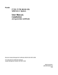
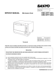
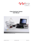
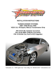
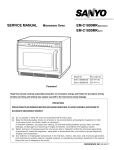
SERVICE MANUAL Microwave Oven EM-C180US PRODUCT CODE NO. 437-452-00 CAUTION WARNING TO SERVICE TECHNICIANS PRECAUTIONS TO BE OBSERVED BEFORE AND DURING SERVICING TO AVOID POSSIBLE EXPOSURE TO EXCESSIVE MICROWAVE ENERGY (a) Do not operate or allow the oven to be operated with the door open. (b) Make the following safety checks on all ovens to be serviced before activating the magnetron or other microwave source, and make repairs as necessary: (1)Interlock operation, (2) proper door closing, (3) seal and sealing surfaces (arcing, wear, and other damage), (4) damage to or loosening of hinges and latches, (5) evidence of dropping or abuse. (c) Before turning on microwave power for any service test or inspection within the microwave generating compartments, check the magnetron, wave guide or transmission line, and cavity for proper alignment, integrity, and connections. (d) Any defective or misadjusted components in the interlock, monitor, door seal, and microwave generation and transmission systems shall be repaired, replaced, or adjusted by procedures described in this manual before the oven is released to the owner. (e)(i) A microwave leakage check to verify compliance with the Federal performance standard should be performed on each oven prior to release to the owner. (For U.S.A) (e)(ii) A microwave leakage check to verify compliance with the Canadian Regulation, HEALTH AND WELFARE, SOR/79-920 should be performed on each oven prior to release to the owner. (For CANADA) REFERENCE NO.SM-640179 CAUTION For microwave energy emission Measurement of energy emission In the area emitting the highest reading, switch the meter to SLOW RESPONSE and take a reading for minimum of three (3) seconds. We recommended the pattern outline shown below when the door surface is surveyed. NOTE: Periodically check to be sure that the probe tip is not worn or dirty. Measurement must be made with the microwave oven operating at its maximum output and containing a load The following U.S. standard applies to microwave ovens: On every service call. A check for microwave energy emission must be made according to the following manner. of 275 ±15 milliliters of tap water initially at 20°± 5° celsius (68±9°F) placed within the cavity at the center. NOTE:The water container must be a 600 milliliter beaker and made of an electrically none conductive material such as glass or plastic. The cook tray must be in place when measuring emission. A properly operating door and seal assembly will normally register emission no greater than 4 mW/cm2 to allow for measurement uncertainty with the cooking shelf or tray in place. All repairs must be performed in such a manner that microwave energy emission is minimal. Follow the instructions supplied with the detector being used and perform an R.F. emission test around the door front, and all edges and vent of the outer case. The cabinet (wrapper) must be in place and the oven fully assembled. When performing an emission survey, with the meter on FAST RESPONSE, the movement of the detector probe shall not exceed one (1) inch per second. 21 CFR 1030.10, Performance Standard for Microwave Ovens. It requires that the power density of the microwave radiation emitted by a microwave oven shall not exceed five (5) milliwatts per square centimeter at any point 5 centimeters (about 2 inches) or more from the external surface of the oven. All microwave ovens exceeding the emission level of 4 mW/cm2 must be reported to Dept. of Service for microwave ovens and the manufacturer immediately. The owner should be told not to use the microwave oven until it has been repaired completely. If a microwave oven is found to operate with the door open, report to Dept. of Service, the manufacturer and CDRH* immediately. Also tell the owner not to use the oven. *CDRH: Center for Device and Radiological Health. The interlock monitor switch acts as the final safety switch protecting the customer from microwave radiation. If the interlock monitor switch operates properly and the door interlock switch fails, the fuse will blow. If this happens, all interlock switches must be replaced. The contacts of the interlock switches may be welded together. - TABLE OF CONTENTS Adjustment Procedures ............................................. 1 Specifications ............................................................ 2 Power output Measurement ...................................... 2 Precautions and Repair Service Tips ....................... 2 Circuit Diagram ......................................................... 3 Test Procedures and Troubleshooting...............4 •`10 Disassembly Instructions .............................. 11 •`14 Exploded View and Parts List ........................ 15 •`22 Overall Circuit Diagram.................................23 •`25 1. ADJUSTMENT PROCEDURES (All service adjustments must be made for minimum microwave energy leakage readings.) (For Canada) TO AVOID POSSIBLE EXPOSURE TO MICROWAVE ENERGY LEAKAGE, THE FOLLOWING ADJUSTMENTS OF THE INTERLOCK SWITCHES SHOULD BE MADE ONLY BY AUTHORIZED SERVICE PERSONNEL. NOTE: If the interlock monitor circuit operates and at the same time the fuse blows with the door open, be sure to replace the relay circuit board , Interlock switch and monitor switch. The service center should have the designated detector to measure the microwave energy leakage after the repair or adjustment. NOTE: Detector to be used at the service center is NARDA 8100, 8200 or the equivalent. INTERLOCK SWITCH, INTERLOCK MONITOR SWITCH AND DOOR SENSING SWITCH ADJUSTMENT Lever stopper (Figure 1) Interlock monitor switch (1) Loosen 2 screws securing the lever stopper. (2) Adjust the lever stopper position so that it is pushed up and pulled backwards until there is zero gap between the latch lever and the switch body on the interlock switch. At the same time there is zero gap between the latch lever and the switch body on the door sensing switch when the door latch is securely locked. (3) Tighten the lever stopper screws securely. (4) Make sure the interlock monitor switch closes after the interlock switch opens when the door is opened very slowly, according to “CHECKOUT PROCEDURE FOR SWITCHES” on page 6. (5) Make sure the interlock monitor switch opens before the interlock switch closes when the door is closed very slowly, according to CHECKOUT PROCEDURE FOR SWITCHES” on page 6. (6)(i) Make sure the microwave energy leakage should be no greater than 4 mW/cm2 to allow to measurement uncertainty when measured with a detector. (All service adjustments must be made for minimum microwave energy leakage readings.) (For US) (6)(ii) Make sure the microwave energy leakage is below the limit of 1 mW/cm2 (at 275cc water load), 5 mW/cm2 (at no load) and 5 mW/cm2 (at 275 cc water load without cabinet) when measured with a detector. Latch Lever Interlock switch (Secondary interlock switch) Latch Lever Door sensing switch (Primary interlock switch) Screws - 3 - Figure 1 2.SPECIFICATIONS A. SINCE NEARLY 4,000 VOLTS EXISTS IN SOME CIRCUITS OF THIS MICROWAVE OVEN, REPAIRS SHOULD BE CARRIED OUT WITH GREAT CARE. B. TO AVOID POSSIBLE EXPOSURE TO MICROWAVE ENERGY LEAKAGE, THE FOLLOWING PRECATIONS MUST BE TAKEN BEFORE SERVICING. (1) Before the power is applied. (a) Open and close door several times to make sure the interlock switch, door sensing switch and interlock monitor switch operate properly. (Listen for the clicking sound from switches.) Make sure the interlock monitor switch is closed after the interlock switch and door sensing are open when the door is opened. (See pages 1 and 6) (b) Make sure the perforated screen and the choke dielectric of the door are correctly mounted. (2) After the power is applied. (a) Open and close the door to see if the interlock mechanism operates properly. (b) Check microwave energy leakage with a leakage detector and confirm the energy leakage is below 5mW/cm2 (3) Do not operate the unit until it is completely repaired of any of the following conditions. (a) Door is not closed firmly against the cavity front. (b) The hinge is broken. (c) The choke dielectric or the door seal is damaged. (d) The door is bent or warped, or there is any other visible damage to the oven that may cause microwave energy leakage. Note: Always keep the seal clean. (e) Make sure that there are no defective parts in the interlock mechanism. (f) Make sure that there are no defective parts in the microwave generating and transmission assembly. (especially wave guide). (4) The following items should be checked after the unit is repaired. (a) The interlock monitor switch is connected correctly and firmly. (b) The magnetron gasket on the magnetron is properly positioned. (c) Waveguide and oven cavity are intact. (No leakage of microwave energy). (d) The door can be properly closed and the safety switches work properly. (e) The oven must be stopped when the door is opened or the time is up. The oven must not be operated with any of the above components removed or bypassed. Microwave output ................ 1,800W to 180W Frequency ........................... 2,450MHz Power supply ....................... 208V, 60Hz Rated current ...................... 13 Amp. Safety Device ...................... Thermal protector(Magnetron) 150°C(270°F)Open (Thermostat) 80°C(144°F)Close Thermistor (Magnetron) 200°C(360°F) Open 108°C(194°F)Close Thermistor(Duct)................120°C(216°F) Open Fuse (Cartridge Type) ................. 250V 10A Micro switch, Relay Interlock Switch Interlock monitor Switch Door sensing Switch and Relay RL-3 and 4 Max. input time .................... Electronic Digital, up to Manual 10min./Memory 30min. Overall Dimensions ........ 422(W)x540(D)x335(H) mm Oven cavity size ............ 330(W)x330(D)x230(H) mm Effective Capacity of Oven Cavity.........19.1liters Net weight ........................... 32Kg 3. POWER OUTPUT MEASUREMENT NOTE: The power output specification, 1800W on this model is measured with IEC measurement. The power output is measured with two(2) liters water is equivalent to 1800W in measurement with IEC, when measured with the following power output. (1)1. Fill two beakers, one liter of tap water respectively 2. Use an accurate thermometer and measure each water temperature respectively. (2) Place beakers side by side in center of the ceramic tray. (3) Close the door,set the “TIME” for two minutes. Touch the “START” key and heat the water for exactly two minutes. (4)Take the beakers out, immediately stir the water and measure the water temperatures respectively. (5) Calculate the temperature rise of water in each beaker. Then calculate the average value of the two temperature rises.( ƒ¢t) (6) The teperature rise shall be in the following range; Average Temp. Rise Minimum 23.1°C Maximum 28.3°C Power output is affected by the line voltage under load. (7) For correct Power output measurement, the line voltage under load must be 208±2Volts. 4.PRECATIONS AND REPAIR SERVICE TIPS PRELIMINARY - 2 - 6. TEST PROCEDURES AND TROUBLESHOOTING PRIMARY CAUTION WINDINGS -DISCONNECT THE POWER SUPPLY CORD FROM THE WALL OUTLET WHENEVER REMOVING THE CABINET FROM THE UNIT. PROCEED WITH TESTS ONLY AFTER DISCHARGING THE HIGH VOLTAGE CAPACITORS AND REMOVING THE LEAD WIRES ON THE PRIMARY WINDING OF THE HIGH VOLTAGE TRANSFORMERS FOR LOWER AND UPPER MAGNETRONS. Filament Windings (SEE FIGURE 3) A. TEST PROCEDURES COMPONENT MAGNETRON Secondary Windings Figure 3 CHECKOUT PROCEDURE RESULT 1) Check for resistance: Across the filament terminal of the magnetron with an ohm - meter on Rx1 scale. Normal reading: Less than 1 ohm. Figure 4 2) Check for resistance: Between each filament terminal of the magnetron and the chassis ground with an ohm-meter on highest scale. Normal reading: Infinite ohms. Figure 5 HIGH-VOLTAGE TRANSFORMER 1) Measure the resistance: With an ohm-meter on R x1 scale. a. Primary winding; b. Filament winding; c. Secondary winding; 2) Measure the resistance: with an ohm-meter on highest scale. a. Primary winding to ground; b. Filament winding to ground; Figure 6 - 6 - Normal reading: Approximately 1.0 ohms Less than 1 ohm. Approximately 60 ohms Normal reading: Infinite ohms. Infinite ohms. Note: Remove varnish of measured point. COMPONENT HIGH-VOLTAGE CAPACITOR Including internal bleeder resistor CHECKOUT PROCEDURE RESULT Measure the resistance: Across two terminals with an ohm-meter on highest scale. Normal reading: Momentarily indicates several ohms, and gradually to 10 meg-ohms. Abnormal reading: Indicates continuity or 10 meg-ohms from the beginning. Figure 7 HIGH-VOLTAGE DIODE Measure the resistance: Across two terminals with an ohm-meter on highest scale. Figure 8 - 7 - Normal reading: Indicate about middle position in one direction (forward) and infinite ohms in the reverse direction, using ohm meter with a 9V battery. NOTE - Some digital meter may show more than 0 ohms or infinite ohms even in a forward direction because the low measuring voltage of the meter does not allow the meter to pass through the high voltage diode. Use an ohm meter with a 9V battery. Abnormal reading: Indicates continuity or infinite ohms in both directions. COMPONENT TOUCH KEY BOARD CHECKOUT PROCEDURE RESULT Measure the resistance between terminals of FPC connector after removing it from S101.(Figure 10) NOTE - When reconnecting the FPC connector, make sure the holes on the connector are properly inserted in hook of the plastic fastener in S101. MATRIX CIRCUIT FOR TOUCH KEY BOARD FPC CONNECTOR When Resistance touched Value Less than 1 K ohms When not touched More than 1 meg ohms When checking the POWER key , connect the ohm-meter as illustrated below. TERMINAL OF FPC CONNECTOR FIGURE 10 CHECKOUT PROCEDURE FOR SWITCHES Disconnect the lead wires from the switches and check for the continuity of the switches, connecting an ohm-meter to its terminals. SWITCHES (SEE Figure 1 on page 1) CHECKOUT PROCEDURES DOOR OPEN DOOR CLOSED INTERLOCK SWITCH Terminals "COM" and "NO" DOOR SENSING SWITCH INTERLOCK MONITOR SWITCH Terminals "COM" and "NC" CAUTION: After checking the switches, make sure that the interlock monitor switch is properly connected according to the CIRCUIT DIAGRAM on page 3. - 8 - WARNING: Primary When removing the cabinet, you must disconnect Winding the power supply cord from the wall oulet for your safety. Only the checkout procedure below needs the power supply on. TAKE GREAT CARE to avoid possible electrical shock. For your safety, proceed with the test only after removing the wire leads from the primary winding of the high voltage transformer Primary Winding Lower Upper COMPONENT CHECKOUT PROCEDURE RESULT Normal reading: POWER P.C.B Check voltage at S104 and S105 after removing each connector (female) from power circuit board. Pin No.3 (Ground) and 4,5, 1,2 at S105. Pin No.1 and 2 at S104. CAUTION: For your safety, proceed with the test only after removing the wire leads from the primary winding of high voltage transformer. Test procedures: a) Make sure that the power supply cord is not plugged in. b) Remove the connector S104 and S105 from the power circuit board. c) Plug the power supply cord : back in. d) And then, measure each voltage. CONTROL P.C.B Measure the voltage: Between test points TP-1, TP-2 ,TP-3 and ground (See figure 16 on page 23) Note - Proceed with the check of the control P.C.B to see if any one of the measured values is different from the specified values. - 9 - Connection Pin No., S105 #3 to #4 #3 to #5 #3 to #1 #3 to #2 S104 #1 to #2 Test point TP, TP-1 TP-2 TP-3 TP-4 Voltage(V) DC 12 DC 16 DC 30 DC 35 AC 2.4 Voltage(V) DC - 5 DC - 12 DC - 16 DC - 35 B. TROUBLESHOOTING CONDITION TROUBLE Power with normal voltage is applied. Place a cup of water inside microwave oven * “TIME”,”1”,”0” ,”0” and “START” keys are touched Fuse(10A) blows off immediately No display cooking time Cooking operation will not start Oven does not heat up CHECK RESULT REMEDY Step down Transformer Shorted Replace H.V Capacitor Shorted Replace Connection of FPC from Touch key board Incorrect Reconnect Power circuit board (See page 7) Voltage incorrect Replace Touch key board (See page 6) Resistance incorrect Replace Control circuit board (See page 7) Voltage incorrect Replace Door sensing switch (See page 7) No continuty Replace Interlock switch (See page 7) No continuty Replace Control circuit board (See pages 7 & 23) Voltage incorrect Replace See “HINT” on page 10 * Note:Oven will not accept settings of 60 through to 99 seconds. TIME must be entered as 1 minute and 39 seconds for 99 seconds. - 10 - CONDITION TROUBLE CHECK Low microwave output Uneven heating RESULT Magnetron Rotation of top or bottom antenna REMEDY Poor oscillation See “HINT” on page 10 Gear motor Rotation has stopped. Repair or replace ° C. ERROR INDICATION The Display will show an error indication for self-diagonosis as follows. “E” means that a service technician is required . “U” means that user can correct the operation. Display E-21 Trouble Other Symptom Thermistor (on duct) sensies Oven stops heating. a temperature of 120°C or Buzzer continuously beeps. Blower motor will stop higher. immediately. Oven stops heating. Buzzer does not beep. Blower motor will stop immediately. Solution Check and remove the cause of the cavity fire or abnormal overheating. This error function will be cancelled when the power cord is unplugged. Check for short-circuit of thermistor itself or wire insulation of thermistor. This error function be cancelled when the power cord is unpluged. E-31 Thermistor (on Magnetron) or thermistor (on Duct) is shorted. E-32 Thermistor (on Magnetron) or Oven stops heating. thermistor (on Duct) is opened. Buzzer does not beep. Blower motor is operated. Check for open-circuit of thermistor itself or improper connection of wire socket of thermistor. This error function be cancelled when the CLEAR key is touched. U-10 Thermistor (on Magnetron) senses a temperature of 200°C or higher. Oven stops heating. Buzzer continuously beeps. Blower motor will stop immediately. Check and remove cause of abnormal overheating (such as operation with no food). This error function will be cancelled when the CLEAR key is touched. U-50 The key for “Start” is not touched within 1 minute after the door is opened or closed . (Remark: The purpose of this function is to avoid accidental operation while the user is not attempting to operate the oven.) This error function will be cancelled when the door is opened and closed. - 9 - THERMISTOR CHART Duct 8000 Magnetron Resistance K¶ 7000 6000 5000 4000 3000 2000 1000 0 Thermistor connector 0 10 20 30 40 Temperature 50 60 “HINT” PROCEDURE FOR DETERMING WHETHER THE UPPER MAGNETRON CIRCUIT OR LOWER MAGNETRON CIRCUIT IS DEFECTIVE. SYMPTOM:One magnetron does not work giving less than normal heat. Caution: Make sure that cabinet (outer wrap) and rear plate are not removed from the oven for your safety. 1.Operate oven as follows. 1)Place a cup of water in the oven 2)Close the door. 3)Touch “CLEAR”, “TIME”, “5”, “0” and “START” keys to operate the oven for 50 seconds with full power level. 2. Determine if the Exhaust air is warm in the following positions.. 1)Put your hand near the exhaust duct outside of the rear plate to feel the exhaust (Never remove the cabinet and rear plate from the oven for your safety when you put your hand near exhausting duct.) 2)If air from the upper position of the duct is not warm,the upper magnetron circuit is defective. If air from the lower position of the duct is not warm,the lower magnetron circuit is defective. Cabinet(outer wrap) Rear Plate Upper position Rear Plate Lower position Exhaust Duct Figure 11 The H.V Transformer for operating the upper Magnetron is located on the inside of the rear plate The H.V Transformer for operating the lower Magnetron is located on the inside of the rear plate - 12 - 7. DISASSEMBLY INSTRUCTIONS - THE OVEN MUST BE DISCONNECTED FROM THE ELECTRICAL OUTLET WHEN MAKING REPLACEMENTS, REPAIRS, ADJUSTMENT OR CONTINUITY CHECKS. BEFORE PROCEEDING WITH ANY REPAIR, WORK , WAIT AT LEAST 1 MINUTE, UNTIL THE CAPACITOR IN THE HIGH VOLTAGE AREA HAS FULLY DISCHARGED. - If the interlock switch, the relay RL-3 and RL-4 or the interlock monitor switch operate properly, determine which of the following is defective : control circuit board, high voltage transformer, high voltage capacitor, high voltage diode or magnetron. D. REMOVING DISPLAY CIRCUIT BOARD (1) Disconnect all lead wires on the Control panel from the Control PCB and Power PCB. (2) Remove 4 screws securing the Control panel Ass’y to the oven cavity. (3) Push up and pull out the Control panel Ass’y. (4) Remove 4 screws securing the Display PCB. (5) Take out the Display PCB and push up the lever end of the plastic fastener and remove the FPC connector from the connector socket S101. CAUTION: When replacing new Display PCB please ensure that all 10 LED heads are positioned exacty into the square holes of the control frame at once. Never force any LED head into the PCB. A. REMOVING INTERLOCK SWITCH (See Figure 1 on page 1) (1) Disconnect all lead wires from the interlock switches. (2) Remove 2 screws securing the lever stopper. (3) Remove 1 screw securing the switches. Then pull out the switches. (4) Make the necessary adjustment, and perform a microwave energy leakage check according to “1. ADJUSTMENT PROCEDURE FOR SWITCHES” on page 1. Check proper operation according to “CHECKOUT PROCEDURE FOR SWITCHES” on page 6. B.REMOVING INTERLOCK MONITOR AND DOOR SENSING SWITCH (See Figure on page 1) (1) Disconnect all lead wires from the interlock monitor switch and door sensing switch. (2) Remove 1 screw securing the these switches. Then pull out the switches. (3) Make the necessary adjustments or replacement of the switch by reversing step (2) and check microwave energy leakage according to “1. ADJUSTMENT PROCEDURE FOR SWITCHES” on page 1. Check proper operation according to “CHECKOUT PROCEDURE FOR SWITCHES” on page 6. E. REMOVING MAGNETRONS (1) Remove 1 screw securing the thermal protector . (2) Disconnect 2 lead wires from the magnetron terminals . (3) Remove thermistor (lower magnetron) by pulling horizontally. (4) Remove 4 hex nuts (upper magnetron) or 2 hex nuts (lower magnetron)securing to the waveguide. (5) Remove magnetrons. (6) Take out the magnetron VERY CAREFULLY. WHEN REPLACING ANY DOOR MICROSWITCH, REPLACE ONLY WITH THE SAME SWITCH SPECIFIED ON THE PARTS LIST. NOTES - When removing the magnetron, make sure that its dome does not hit any adjacent parts, or it may be damaged. - When replacing the magnetron, be sure to install the magnetron gasket in the correct position and be sure that the gasket is in good condition. - After replacing the magnetron, check the microwave energy leakage to ensure it is below the limit of 5mW/cm2. (For US) C. REMOVING FUSE Remove the 10A fuse with screwdriver. NOTES - When replacing the 10A fuse, be sure to use the exact repair part. - If the 10A fuse blows immediately, check the primary and secondary interlock switch, the relays RL-3 and RL-4 (on the control circuit board) and the interlock monitor switch according to “CHECKOUT PROCEDURE FOR SWITCHES” on page 6. Make sure to check the microwave energy leakage according to “1. ADJUSTMENT PROCEDURE FOR SWITCHES” on page 1, when the primary and secondary interlock switches, the relay RL-3 and RL-4 or the interlock monitor switch is adjusted or replaced. - After replacing the magnetron, be sure to check the microwave energy with a leakage detector and confirm it is below the limit of 1 mW/cm2 (at 275cc water load),5 mW/cm2 (at no load) and 5 mW/cm2 (at 275 cc water load without cabinet) when measured with a detector. (For CANADA) - 13 - HINT FOR LAMP-CHANGE Before removing the bulb access panel, pull out the main-plug. Change the faulty bulb and secure the bulb access panel. Plug the cord back in and check operation. F. CHANGING POWER SUPPLY CORD (See exploded view on page 15) (1) Unfasten 1 screw for ground and pull out the 2 wires of the power cord from the terminal plate. (2) Remove 1 screw for the bottom bracket of the cord bushing. (3) Install the new power supply cord with the reverse procedure of above (1) to (2). WARNING: For changing the power supply cord, never use other than the following. Key No. Order No. 5 617 140 1318 6 617 140 1332 7 617 140 1349 Parts Name Power cord Ass’y Cord bush Bottom bracket G. REMOVING CERAMIC TRAY ASS’Y (See Fig.12 ) (1) Take off the cabinet. (2) Put (insert) a screwdriver in the 9 mm diameter hole located at the lower hinge of left side of the oven cavity. Push the tray up with the screwdriver. (3) Open the door and take out the tray very carefully. Door NOTES - After replacing the door, be sure to check that the interlock switch, the door sensing switch and the interlock monitor swich operate normally. (See pages 1 and 6) - After replacing the door, check for microwave energy leakage with a leakage detector. Microwave energy leakage must be below the limit of 5mW/c ‡u.(For US) - After instaling the door, check for microwave energy with a leakage detector and confirm that the leakage is the below the limit of 1 mW/cm2 (at 275cc waterload),5 mW/cm2 (at no load) and 5 mW/cm2 (at 275cc water load without cabinet) . (For CANADA) I.HOW TO RESET THE MEMORY OF ACCUMULATIVE COOKING TIME 1. Push the keys step by step as follows, “ CLEAR “, “ TIME “, “ 8 “, “ 8 “, “ 8 “, “ 1 “ “ START “, “ START “. The display will show accumulative cooking time in display window. 2. Then push the keys as follows. “ 0 “, “ MEMORY “. The Memory of Accumulative cooking time will be cleared. J.RELEASING TYPE CONNECTOR This oven is provided with locked type connectors. When you remove a connector, pull the connector while releasing the lock by pressing “A” point shown below. Do not pull the wire of the connector. Connector: S1, S2, S102, S104, S105 (Figure 13) A A Hole Figure 13 Figure 14 Pull connector case (Never pull the wire) Screw driver Figure 12 H.REMOVING DOOR Remove 2 hex nuts securing the upper hinge, remove 3 hex nuts securing the lower hinge and remove 1 special screw securing the door arm (located at the bottom of the door sash). Figure 15 - 14 - K. ADDITIONAL FUNCTIONS The following functions can be completed by the key operation described below. The Accumulative cooking time and the number of door opening /closings can be observed. The Type and level of the buzzer sound can be selected. The “display of remaining cooking time when cooking is temporarily stopped due to door opening” can be selected. The “Accumulative cooking time period” will inform the service technician of the life expectation of the magnetron or other parts. Key Operation Step OPERATION KEY 1 CLEAR STOP 2 3 TIME 8 • • • DISPLAY WINDOW Press CLEAR / STOP key. LOW MED. HIGH LOW MED. HIGH LOW MED. HIGH Press TIME key. Press 8 three times. Key operations at Step 1 thru Step 3 are common to all functions. Proceed with the key operation at Step 4 for your desired functions. • Select the function to press the number key 4 5 6 1 ... Accumulative cooking time. 2 ... The number of door operations. (See “HINT” at Step 6) 3 ... Indication of remaining cooking time (when cooking is interrupted by door opening). 4 ... To cancel remaining cooking time. 5 ... Tone of the buzzer on cooking completion. (Pip, Pip, Pip) 6 ... Tone of the buzzer on cooking completion. (Peep) 7 ... The buzzer off. 8 ... The buzzer on. e.g. Number 1 key is pressed for “Accumlative cooking time period” 1 START • • MED. HIGH Press START key. All 4 digits will be flashing. START Press START key again. The number “215”shows total cooking time in hours. When number key other than 1 or 2 is pressed at step 4, “0” appears in display window and the setting has been completed. Note:When number “2” is depressd at Step 4 above the displayed figure shows the number of door operation ••100 e.g. “20” displayed=2000 door operations. LOW MED. HIGH LOW MED. HIGH LOW MED. HIGH LOW MED. HIGH • • • • 7 LOW CLEAR STOP Press CLEAR / STOP key to clear the display for the option 1 and 2. • The function is cleared and “0” will appear in the display window. - 15 - Maintenance: The microwave ovens are designed, manufactured, and tested for years of dependable operation. However, the oven may require service from time to time if the consumable components listed below are not replaced at the appropriate time. For protection from unexpected service calls and undue inconvenience, we recommend that the user has the listed parts replaced at the intervals below, (at customer cost). This will avoid the trouble of repeated service calls after the expiration of the warranty period. Consumable components: When more than 1,250 hours of accumulative cooking time or more than 200,000 cycles of door opening/closing is observed by key operations (See page 13 for more information), the following consumable components should be replaced. (Maintenance light in window display indicates when accumulative cooking time reaches 1,250 hours.) Light 1. Magnetron Tube, Part No. 415 002 6408 2. Printed Circuit Board-Relay, Part No. 617 137 3844 3. Switch base Assembly, Part No. 617 205 1208 4. Door Latch, part No. 617 068 1087 When more than 2,000 hours of accumulative cooking time is observed, the following consumable components should be replaced. 5. Blower motor, Part No. 617 140 1370 When slow rotating of blower motor is observed after removing dust from blower motor, blower motor must be replaced. 6. Door hinge, Part No. 617 120 3028 When a worn door hinge is observed and proper door adjustments can not be made, the door hinge must be replaced. 7. Door Assembly, Part No. 617 178 0734 When a worn door pin is observed and proper door adjustments can not be made, the door assembly must be replaced. - 16 - 8. EXPLODED VIEW AND PARTS LIST Main body Parts-1 NOTE: All component have special characteristics for safety and must be replaced using parts listed in this manual. All service on M/W ovens should be performed by a qualified technician using approved testing equipment. Customers should not attempt replace component marked with a symbol. - 17 - NOTE: All component have special characteristics for safety and must be replaced using parts listed in this manual. All service on M/W ovens should be performed by a qualified technician using approved testing equipment. Customers should not attempt replace component marked with a symbol. - 18 - Main body Parts-2 NOTE: All component have special characteristics for safety and must be replaced usnig parts listed in this manual. All service on M/W ovens should be performed by a qualified technician using approved testing equipment. Customers should not attempt replace component marked with a symbol. - 20 - NOTE: All component have special characteristics for safety and must be replaced using parts listed in this manual. All service on M/W ovens should be performed by a qualified technician using approved testing equipment. Customers should not attempt replace component marked with a symbol. - 21 - Wiring of High voltage Circuit Upper Magnetron Red wire Lower Magnetron BACK Red wire Filament Winding Black Pink/Light Blue Red wire Lower Transformer Blue/Blue Filament Winding Wiring of Switches FRONT Brown Upper Transformer Red wire Monitor switch Brown(C Inside) Orange(C) Blue(NC Inside) White (NO) Upper Capacitor Pink(NO Inside) Light Blue (NC) Lower Capacitor Brown Orange White White Yellow Interlock switch Purple Purple Door sensing switch March/99 Printed in JAPAN - 28 -