1
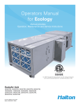
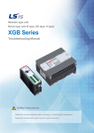
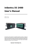
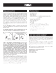
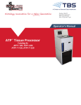
Operators Manual Operation, Maintenance and Service Capture RayTM Hoods with Water Wash and UV Technology Model: KVE-WW-UV, KVC-WW-UV INSTALLATION INSTRUCTIONS Suspending and Mounting Determine location of 1/2” (13mm) diameter hanging rods. All thread rods are recommended for use with front support brackets provided. All hanging rods should have double nuts. Rods should be threaded 4” (102mm) minimum for verticle adjustment. See figure 1. Hanging rods by installer. Exhaust hoods are shipped in maximum lengths of 14’-0”. When installing multiple sections, we recommend hanging the section individually then fasten together as per the installation drawing. See figure 2. Install U-channel strips provided on multiple bank sections between interior section ends at bottom. All exhaust hoods must be hung level and plumb. Note: Allow 100lbs (45kg) per linear foot hanging weight. Do not lift exhaust hoods from their end panels. Lift from four corners All exhaust hoods and control panels are fitted together and factory tested prior to shipping for alignment and operation. Duct Connections Duct connections meet NFPA 96 of applicable local codes. Size of connection is indicated on exhaust hood drawing. Connection to be made after exhaust hood is hung. PROPER LOCATION IS ESSENTIAL Locating the exhaust ventilator with sufficient overhang over the cooking equipment is mandatory for proper capture and extraction of grease and smoke. It is important that the installer check with Kitchen Equipment Contractor for accurate location of the cooking bank, exhaust hood and control panel. Capture RayTM Water Wash Operation & Maintenance & Service Manual 2 CJUVWW/032009/rev1/EN Exhaust hood shop drawings show recommended mounting height from finished floor to underside of exhaust hood at front edge. All hanging bracket locations are also indicated. Electrical, ductwork and air requirements are also indicated on the exhaust hood show drawings. Capture RayTM Water Wash Operation & Maintenance & Service Manual 3 CJUVWW/032009/rev1/EN FIGURE 1 HOOD INSTALLATION DETAILS Capture RayTM Water Wash Operation & Maintenance & Service Manual 4 CJUVWW/032009/rev1/EN FIGURE 2 SPLICE STRIP / U-CHANNEL ASSEMBLIES METHOD OF OPERATION Capture RayTM Water Wash hood systems operate properly when the KSA grease extractors and backup mesh filters are properly installed, the UVC lamps are clean and the exhaust fan is turned on. The system is engineered to reduce maintenance and keep service issues to a minimum. The unit is constructed of stainless steel with removable KSA grease extractors and GPS filters for interior inspection and cleaning. Make-up Air Supply Make-up air must be provided to replace the air exhausted through all kitchen exhaust systems. The “make-up air” may be supplied through a front face discharge plenum on the Capture RayTM Water Wash hoods or from registers in the kitchen area. Velocities of “make-up air” should be kept to a minimum especially near the exhaust hood perimeter. > CAUTION: High “make-up air” velocities will distrub smoke capture. Many codes call for a number of air changes per hour. This should be reviewed with the entire ventilation requirements of the facility. METHOD OF DETERMINING AIRFLOWS The air flow through the Capture RayTM hoods is determined by using the testing and balancing (T.A.B.) port as showin in figure 3. T.A.B.TM - TESTING AND BALANCING PORTS Capture-Ray Hood Example dPm (inches WC) 2.1 1.9 1.7 1.5 1.3 1.1 0.9 0.7 0.5 150 170 190 210 230 250 270 290 Airflow (cfm/ft) (based on heat load design) Capture RayTM Water Wash Operation & Maintenance & Service Manual 5 Measured Pressure ∆Ps = 1.4" CFM/ft = 238 CJUVWW/032009/rev1/EN The capture-jet and exhaust air flows are easily and accurately determined by matching the pressure difference from the T.A.B. ports mounted in each plenum. Corresponding air flows, in cfm per foot of hood, can be read from the diagrams provided in this catalog. Halton AccuFlow Overview The AccuFlow by Halton is a Bluetooth equipped device intended to monitor the exhaust airflow rate of Halton Capture Jet hoods and alarm kitchen staff if the hood is above or below design. The device (shown below in Photo 1) has two taps (Photo 2) that are connected to the exhaust hood to monitor the differential pressure between ambient air and the exhaust plenum; the T.A.B Port reading. AccuFlow installs in Capture Jet plenum for easy viewing and access. The device shares an electrical circuit with the Capture Jet fan. Photo 1 – Halton AccuFlow Photo 2 – AccuFlow Pressure Taps Connects to ambient (room) air Connects to T.A.B. port Exhaust airflow rate is determined in the same fashion as other Halton Capture Jet hoods; each hood has a unique K-Factor dependent upon model. The actual airflow is compared to the design value and an alarm is enabled if airflow is above or below the specified range. Capture RayTM Water Wash Operation & Maintenance & Service Manual 6 CJUVWW/032009/rev1/EN Plastic tubing connected to (-) port of Accuflow device Operation Each AccuFlow is programmed at a Halton Company manufacturing facility. To program the device, the Bluetooth feature is enabled and personnel input necessary parameters. Programming can be completed with a Windows Mobile enable smart-phone (PDA) or PC with the required software installed. Programmed values include: Design Airflow, High Airflow Delta, Low Airflow Delta and K-Factor. Design Airflow is determined using the Halton HELP software and the Low and High Airflow Delta are defined as +/- ten percent of design airflow. K-Factors have been determined by Halton Research and Development personnel. Bluetooth capability also allows an Authorized Service Agent to determine the airflow of an exhaust hood on site if an alarm is present. This information can be conveyed to Halton personnel for troubleshooting. Alarms Alarms are enabled when design airflow is above or below ten percent of design airflow. An alarm is visible on the front of the Accuflow, see Photo 3 below. Photo 3 – AccuFlow Alarm Location Capture RayTM Water Wash Operation & Maintenance & Service Manual 7 CJUVWW/032009/rev1/EN Indications of alarm status (under or over design) are printed on the device. If the LED indicator is steady, the hood is at design airflow. Alarms are differentiated by the number of blinks per second; 1 blink per second indicates the hood is under design, 2 blinks per second indicates the hood is over design. Troubleshooting AccuFlow Problem Probable Cause Solution No lights Illuminated on AccuFlow device Loose or improper electrical connections - Verify or reconnect electrical connections -Not reaching design airflow -Increase fan speed -Plastic tubing disconnected from Accuflow device or TAB port -Reconnect -Broken plastic tubing -Clean TAB port Low airflow alarm -Replace tubing -Dirty or plugged TAB port in exhaust plenum Capture RayTM Water Wash Operation & Maintenance & Service Manual Bad Device - Replace 8 CJUVWW/032009/rev1/EN Failure SERVICE INSTRUCTIONS WARNING Removal of the UVC lamps and access to the control panel is by a Halton Factory Authorized Trained Service Agency only. Capture RayTM Component Cleaning During the day grease accumulates in the interior of the KSA grease extractor and the GPS (grease particle separator) filter. Therefore, they must be cleaned on a daily basis. This can be accomplished by running the filters through a full wash cycle. > Caution: If the KSA grease extractor and GPS filter are not maintained, accumulated grease can create a fire hazzard and impair the overall performance of the hoods. Automatic Duct Protection Automatic fire suppression is accomplished by use of a thermal fusible link in the exhaust collar and detection line above the appliances. If the fusible link should activate, it would close the fire damper (if supplied) and automatically release the suppression agent. NOTE: Depending on the type of cooking equipment covered, an additional surface fire protection system is typically required. In the event of a fire, the surface fire protection system would normally activate and discharge before high temperatures would close the fire damper (if supplied). All gas, and/or some electric, cooking equipment must also be provided with a “fuel shut-off” device when the surface fire protection system is activated. Duct and plenum protection is required on Capture RayTM hoods. Consult local authorities. CROSS SECTION OF CAPTURE RAYTM WATER WASH HOOD SPEED CONTROLLER TOP INTAKE (STD) UV CASSETTE WATER MANIFOLD TAB PORTS GPS FILTER (Secondary Filter) ACCESS DOOR BALLAST BOX KSA GREASE EXTRACTOR (Primary Filter) 9 CJUVWW/032009/rev1/EN CAPTURE JET AIR (FRONT & SIDES) DRAIN Capture RayTM Water Wash Operation & Maintenance & Service Manual FRONT INTAKE (OPTIONAL) MAINTENANCE AND CARE INSTRUCTIONS WARNING Unauthorized access or tampering will result in serious eye damage. CAUTION Access and service is by a Halton Factory authorized personnel only. You have purchased the finest kitchen ventilation equipment available anywhere. Like any fine piece of equipment, it should be given regular care and maintenance. NOTE: It is crucial that a Preventative Maintenance Program is contracted and performed by a Halton Factory Authorized Trained Service Agency only. Your Halton dealer is well qualified to co-ordinate this service. Periodic inspections are recommended to check the operation. When corresponding with the factory or your equipment dealer regarding service issues or replacement parts, be sure to refer to the unit by the correct model number including perfix and suffix letters and numbers and serial numbers if shown. The model plate affixed to the unit contains this information and is mounted on the inside of the hood wall. REGULAR MAINTENANCE ENSURES PEAK PERFORMANCE. CLEANING EXTERIOR STAINLESS STEEL - Normal soil may be removed with a stainless steel detergent and warm water applied with a cloth. NOTE: Remove grease build-up from fixed baffles and other interior surfaces. To remove grease that has baked on, apply cleanser to a damp cloth or sponge and rub cleanser on the metal in the direction of the polishing lines of the metal. NEVER RUB WITH A CIRCULAR MOTION. Soil and burnt deposits which do not respond can usually be removed by rubbing the surface with Scotch-Brite scouring pads or stainless scouring pads. DO NOT USE ORDINARY STEEL WOOL. Capture RayTM Water Wash Operation & Maintenance & Service Manual 10 CJUVWW/032009/rev1/EN Heat tint can be removed by a vigorous scouring in the direction of the polish lines using Scotch-Brite scouring pads or a stainless scouring pad in combination with a powdered cleanser. INSTRUCTIONS FOR RE-LAMPING ITEM NO. 1 2 3 4 5 QTY. 6 12 2 12 2 DESCRIPTION UV Lamp UV Lamp Grommet UV Cassette End - Water Wash Lamp Socket End Cap Gasket PART NUMBER 10373 (66”) or 10374 (38”) 10377 53195XX 10376 10593 1 3 5 2 4 Instruction for Re-Lamping Capture RayTM Water Wash Operation & Maintenance & Service Manual 11 CJUVWW/032009/rev1/EN 1) With the cassette removed from the hood, remove the screws from the end caps #3. 2) Unplug the lamps from lamp sockets #4. 3) Carefully slide each blub through the lamp grommetts. 4) Remove the lamp grommetss #2 and replace with new grometts. 5) Carefully slide the new lamps through new grommetts and re-connect lamp sockets #4. 6) Re-install end caps #3 and attach with screws. REPLACEMENT PARTS SCHEMATIC TOP INTAKE (STD) "UV" Cassette 38"L = #2806 66"L = #2807 Incandescent Light Base Incandescent #2802 Light Globe #2801 GPS Filter #2804 KSA Grease Extractor #2800 PREVENTATIVE MAINTENANCE Replacement Part Numbers 38” UV Cassette 2806 66” UV Cassette 2807 GPS Filter 2804 Preventative maintenance is necessary for efficient operation of your Capture RayTM Water Wash hood. Daily - Clean exhaust hood exterior. See cleaning exterior. Run the hood wash cycle. Monthly - The Capture RayTM Water Wash hood should be inspected regulary. The UV tube frames and controls should be verified for proper Incandescent Light Base 2802 operation and cleaning. Check to ensure that all indicator lights are on, and wipe down the UVC Incandescent Light Globe 2801 lamps with a damp cloth to remove any residue. Run a complete test of the system and alarms. WARNING - Removal of the UVC lamps and Control Inspect filters for grease accumulation and clean Panel is by a Halton Factory Authorized Trained if required. KSA Grease Extractor 2800 Service Agency only. It is crucial that a Preventative Maintenance Program is contracted and performed Although this is listed as monthly, it may be extended or by a Halton Factory Authorized Service Agency only. shortened depending on the type of cooking and hours of operation. Two different nozzles are supplied with the Capture Ray Water Wash Hood. Replacement nozzles are obtained from Spraying Systems Co. Catalog number B5 nozzle washes the UV cassette, the back of the mesh filters, the front of the KSA grease filter, and make up a portion of the nozzles in the wash manifold that washes the inside of the KSA grease filter. The B5 nozzles have an inlet connection size of 1/8”, orifice diameter 0.031”. The balance of the nozzles which wash the inside of the KSA grease filter are Catalog number C30. The C30 nozzles have an inlet connection size of 1/8”, orifice diameter 0.023”. Maximum recommended water pressure is 80 psi, typical water pressure would be 40 psi. Capture RayTM Water Wash Operation & Maintenance & Service Manual 12 CJUVWW/032009/rev1/EN Water Wash Nozzle Information CONTROL PANEL OPERATION The UV Water Wash control panel is designed to operate the UV lamps only under safe conditions and warn when there are lamp failures, fan failures, the lifetime of the lamps has been exceeded or other operational failures. If these solutions do not fix the problem, refer to the Troubleshooting Guide later in this manual. If an alarm goes off on the panel it indicates then there is a problem with the UV operation. To silence the alarm, press the “MUTE” button; however, the indicator lamps will remain lit. To reset the 10,000 hour clock, it is necessary to use the keypad to reset the timer. DISPLAY Lamp Failure CAUSE A lamp has failed, the voltage to the lamp is too low, or the lamp ballast has failed. Either the fan is at a lower speed or belt has broken No Air Flow Either a KSA filter is not in place in the hood or the cassette access door is open. 10,000 Hour Maintenance The expected lifetime of the lamps have been reached. Fire The fire system has been activated. UV Door Open Filters are removed. SOLUTION - Check line voltage - Replace UV Lamp - Replace lamp ballast if needed - Examine and tighten or replace fan belt if needed. - Replace fan if needed. - Check that all filters are installed and the cassette access door is closed and fastened. - Replace the UV lamps. Failure to do this will cause the system to not be efficient. 7" STANDARD CONTROL PANEL (FEED OUT) (SUPPLY IN) SYSTEM OK ALARM 40" RUN WASH PLUMBING COMPARTMENT PLUMBING COMPARTMENT HINGED DOOR HINGED DOOR BUZZER ELECTRICAL COMPARTMENT BLACK FLOW PREVENTOR 5 GALLON DETERGENT RESERVOIR Capture RayTM Water Wash Operation & Maintenance & Service Manual 12" 47" 13 CJUVWW/032009/rev1/EN 28" A.F.F. HINGED DOOR CONTROL PANEL - INPUT - OUTPUT DESCRIPTION SAFETY SWITCHES These switches are monitored when the unit is turned On; in Off mode, they are ignored (except for the Fire Switch.) They are listed in the order of precedence in case events occur simultaneously. Fire Switch – Normally Open switch connected to terminals 8 and 10 • When switch is closed, UV Lamp output is shut off immediately • Alarm lamp(red color)lit and display shows FIRE • Exhaust and Makeup fans may be shut off (depending on internal programming) • This particular alarm remains active even when unit is in Off position • When switch is closed, UV shuts off immediately without delay on the hood where alarm occurs and for the rest of the hoods UV continue to run(UV at the hood is the only output affected) • After Flow Alarm Delay time, Alarm lamp is lit, and display shows No Air Flow • If switch is open again thereafter for at least 1 second, UV lamp output resumes operation and error is cleared. (1 second delay to avoid contactor flickering when pressure is unstable) Capture RayTM Water Wash Operation & Maintenance & Service Manual 14 CJUVWW/032009/rev1/EN Pressure Switch Normally Closed switch (stays open during operation) connected to terminals 8 and 18 UV Lamp Failure Switch Normally Closed switch located on lamp ballasts (stays open during operation) connected to terminals 8 and 16 • This switch is monitored only if panel is in ON position and UV Lamp output is on • When switch is closed (condition must exist for 60 seconds), all outputs remain on • Alarm lamp is lit, and display shows Lamp Failure Miscellaneous Switches 1 (mounted on the UV doors and baffle filters) Normally open switch-closed when in place, (Multiple switches connected in series) connected to terminals 8 and 19 • When switch is opened, UV shuts off immediately without delay on the hood where alarm occurs and for the rest of the hoods UV continue to run(UV at the hood is the only output affected), • Fans remain on • Alarm lamp is lit and display shows UV door open Miscellaneous Switches 2 (mounted on the KSA filters) Normally open switch-closed when in place, (Multiple switches connected in series) connected to terminals 8 and 17 • When switch is opened, UV shuts off immediately without delay on the hood where alarm occurs and for the rest of the hoods UV continue to run(UV at the hood is the only output affected), • Fans remain on • Alarm lamp is lit and display shows Filter removed Remote AUTO/WASH/RUN switch Used to remotely turn the system in RUN and WASH • If remote control for the panel is needed, this switch is on AUTO position • This enables panel to be controlled from time clock, BMS or similar systems. OUTPUTS UV LAMPS output – terminals 1 and 5 120 VAC to energize contactor coil switching power to UV lamps, Exhaust Fan – terminals 1 and 2 AC voltage to energize exhaust fan starter,120 VAC. Alarm signal output – Terminal numbers to be assigned. Dry contacts which close/open on certain alarms can be provided to send signal to remote monitoring system. Capture RayTM Water Wash Operation & Maintenance & Service Manual 15 CJUVWW/032009/rev1/EN Makeup Fan – terminals 1 and 3. AC voltage to energize makeup fan starter,120 VAC. FRONT PANEL APPREANCE There are two indicator lights located at the top of the panel: - Green light –“System OK” indicates when system is in normal operating mode and no alarms are occurring. - Red light –“Alarm” indicates when there is a failure appearing in the system - TD 200 Siemens display ( text display )- shows text messages (displayed in two rows) - system status - Soft touch buttons on the display( square shape –located bellow messaging display): - Wash time button to set the time for washing cycle (second button from left) - UV Hours display to show : (fourth button from left) - Total to display the total number of hours of UV operation - Clean to display the number of hours of operation since last UV cleaning - Maintenance - If UV Lamp failure is detected, Alarm red light blinks every 0.5 sec. Capture RayTM Water Wash Operation & Maintenance & Service Manual 16 CJUVWW/032009/rev1/EN If Total Time Since Last Cleaning reaches 1600 hours, or if Total Hours Of Operation reaches 10,000 hours, Alarm red light blinks. OPERATING MODES - SEQUENCE OF OPERATION OFF MODE • The unit displays WASH DONE SYSTEM OFF • All outputs are off • Indicator light “System OK” is lit. • Statistics can be consulted/cleared using appropriate keys RUN MODE • Put selector switch ”RUN/WASH” in RUN position • The unit displays FAN ON UV ON • Exhaust fan is on • Make up air fan is on • 120 V sent to UV lights contactor( When unit detects air flow ,UV lamps are turned on. • Statistics can be consulted/cleared using appropriate keys WASH MODE • Select RUN/WASH switch in WASH position-turn off sequence is as follows: • The unit displays WASH ON 90 SEC DELAY first row • The unit displays 30 SEC FAN OFF DELAY second row • Make up air fan is off • UV lamps are off • Exhaust fan stays 30 more seconds for ozone removal purpose ,then shuts down. • Washing cycle is delayed for 90 seconds allowance for fan to stop. Automatically after 90 seconds of delay panel is going to washing cycle : • The unit displays WASH ON_____MIN • The display is showing the current time on washing hoods. • The hot water solenoid is on • Detergent pump is on • Washing cycle finishes after preset time ( by default 3 min)-this is adjustable by wash time setting button After the wash cycle finishes by program in the panel Rinse mode starts: RINSE MODE • The unit displays RINSE SEQUENCE • By default delay of 1 min will appear until Rinse starts Capture RayTM Water Wash Operation & Maintenance & Service Manual 17 CJUVWW/032009/rev1/EN After one minute delay Rinse will start: • The hot water solenoid is on • Detergent pump is off • Rinse will be on for one minute and then automatically system shuts down in stand by. • The unit displays WASH DONE SYSTEM OFF This message will persist until operator put the selector switch in RUN. VIEWING/CLEARING STATISTICS • Two types of statistics are recorded: Total Hours Of Operation and Total Hours Since Last Cleaning • These are simply displayed as a number of hours. • Statistic is viewed by pressing either Total or Clean. Display returns to normal as soon as key is released. • Statistic can be cleared by pressing the Mute key while pressing the statistic key. • Wash time can be changed easily by a simple procedure 1. Press “WASH TIME SETTING” button on the electronic text display. Currently set value in minutes is displayed. 2. Press the “ENTER” button, a blinking cursor appears 3. Use the “” up and down arrows to set desired wash time. 4. Press “ENTER” again to finish. FACTORY DEFAULT VALUES: The unit has pre programmed default values MAXIMUM UV CLEAN TIME Maximum time allowed before UV Service alarm comes on is 1600 hours. MAXIMUM UV OPERATING TIME Maximum time allowed before UV Service alarm comes on is 10,000 hours. FAN TURN-OFF DELAY When unit is turned Off, exhaust fan remain on for a certain period until residual ozone is evacuated. The value is 30 sec. Capture RayTM Water Wash Operation & Maintenance & Service Manual 18 CJUVWW/032009/rev1/EN FAN OPERATION DURING FIRE When unit detects the Fire input, it shuts off the UV Lamp output. Fans are also shut off according to this parameter. By default exhaust fan is off in the fire mode. AIRFLOW ALARM DELAY This sets the maximum time allowed for the pressure switch to be closed in On mode. After this delay (in seconds), the unit will sound the alarm to alert the operator. ELECTRICAL WIRING/CONNECTIONS Capture RayTM Water Wash Operation & Maintenance & Service Manual 19 CJUVWW/032009/rev1/EN Two electrical wiring diagrams are shown below: 1) Control Panel electrical wiring diagram 2) Field wiring diagram 20 CJUVWW/032009/rev1/EN Capture RayTM Water Wash Operation & Maintenance & Service Manual TROUBLE SHOOTING GUIDE Control Panel Message: No Air Flow PROBLEM CAUSE SOLUTION Field Wiring or Breaker - Verify field wiring for proper connections - Check fuse at control panel Fan on but no UVC lamps UV door open Control Panel Message: No Air Flow Pressure switch malfunction Power off within ten seconds Control Panel Message: No Air Flow UV failure lamp flashes on and off Control Panel Message: Lamp Failure Capture RayTM Water Wash Operation & Maintenance & Service Manual - Close door - Check wiring - Check air tube for blockage - Replace pressure switch if necessary No air flow Panel not reading air flow - Check fan for proper operation - Check pressure switch connection and tube - Replace pressure switch if defective UV lamp failure or lamp ballast failure - Replace failed cassette with a new one. - Replace ballast if defective. 21 CJUVWW/032009/rev1/EN INOPERATIVE Exhaust fan and UVC lamp will not function Capture RayTM Water Wash Operation & Maintenance & Service Manual 22 CJUVWW/032009/rev1/EN EXHAUST FIRE DAMPER ASSEMBLY HALTON LIMITED WARRANTY Halton (“Manufacturer”). Warrants only to its direct purchasers and to no others, that all products manufactured by the Manufacturer shall be free from defect in materials and workmanship for a period of twelve (12) months from the date of the original installation and start-up or eighteen (18) months from date of shipment, whichever occurs first. All products sold but not manufactured by Manufacturer will be warranted for a period of twelve (12) months from date of shipment. For products manufactured by the Manufacturer we agree to pay any reasonable labor costs necessary to repair or replace, at Manufacturers option, defective parts or materials for a period of twelve (12) months from date of original installation and start-up or eighteen (18) months from date of shipment, whichever occurs first. All labor costs subject hereto shall be performed during standard work hours at straight-time rates. For products sold but not manufactured by the Manufacturer we agree to pay any reasonable labor costs necessary to repair or replace, at Manufacturers option, defective parts or materials for a period of (90) days from date of original installation and start-up or (12) months from date of shipment, whichever occurs first. All labor costs subject hereto shall be performed during standard work hours at straighttime rates. Purchaser shall pay incurred premium labor charge, including overtime, weekends and holidays. Travel time, service charges, miscellaneous tools, material charges, and labor charges resulting from inaccessibility of equipment will not be paid by Manufacturer. This LIMITED WARRANTY SHALL APPLY ONLY to products that have been installed and maintained in accordance with the installation and Care Instruction Manuals. Purchaser shall be solely responsible for adhering to the instructions and procedures set forth in the said instruction manuals. This LIMITED WARRANTY SHALL NOT BE APPLICABLE to any damage or defect resulting from fire, flood, freezing or any Act of God, abuse, misuse, accident, neglect or failure to adhere to all instructions set forth in the installation and Care Instruction Manuals. Furthermore, this limited warranty shall not apply to any product that has been altered, unless such alteration has been approved in writing by a duly authorized representative of the manufacturer. In no event shall the manufacturer be liable for any loss, expense, personal injury or consequential damage, of any kind or character, as may result from a defect in material, and/or workmanship, however caused. EXCEPT AS IS EXPRESSLY SET FORTH IN THIS LIMITED WARRANTY, MANUFACTURER MAKES NO WARRANTY OF MARKETABILITY FOR FITNESS OR ANY PARTICULAR PURPOSE. NEITHER DOES MANUFACTURER MAKE ANY WARRANTY, EXPRESSED OR IMPLIED, WITH RESPECT TO PRODUCTS SOLD BY MANUFACTURER OR AS TO THE USE THEREOF. Halton Company 101 Industrial Drive, Scottsville, 42164 USA Tel: 270-237-5600 Fax: 270-237-5700 Website address www.haltoncompany.com Halton Indoor Climate Systems, Ltd. 1021 Brevik Place • Mississauga, ON L4W 3R7 CANADA Tel: 905-624-0301 Fax: 905-624-0301 Website address www.haltoncanada.com