1
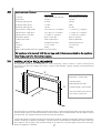
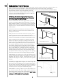
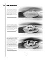
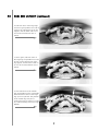
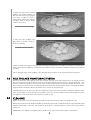
COLIMA
Fuel Effect Gas Fire
INSTALLATION, SERVICING AND
USER INSTRUCTIONS
All instructions must be handed to the user for safekeeping
Revision B 04/03
Country(s) of destination: GB, IE
Focal Point Fires plc, Avon Trading Park, Christchurch, Dorset BH23 2BT
: (01202) 499330
Fax: (01202) 499326
www.focalpointfires.co.uk
e-mail: [email protected]
INST
TALLAT
TION INST
TRUCT
TIONS
Prelim
min
nary Notes Before Installation
n
This appliance is an inset live fuel effect gas fire that provides radiant warmth.
The fire is designed to fit into a purpose made builder’s opening, and use natural draught flues as listed in the Installation Requirements.
The appliance must be installed by a competent person in accordance with
Gas Safety (Installation and Use) Regulations 1998. It is strongly recommended
that a CORGI registered engineer be used for this purpose.
Read all these instructions before commencing installation.
This appliance must be installed in accordance with the rules in force and only
used in a sufficiently ventilated space.
This appliance is factory set for operation on the gas type, and at the pressure
stated on the appliance data plate.
Secction
1.0
2.0
3.0
4.0
5.0
6.0
7.0
8.0
1.0
Secction
9.0
10.0
11.0
11.1
11.2
12.0
13.0
14.0
15.0
16.0
Pag
ge No.
Contentss
1
Important Notes
2
Appliance Data
2
Installation Requirements
3
Site Requirements
3
Ventilation
4
Unpacking the Appliance
4
Component Checklist
4
Preparing the Appliance
Contentss
Preparing the Opening
Gas Supply
Fitting the Firebox
Cable Fixing
Gas Connection
Fuel Bed Layout
Fitting stone effect frame
Testing & Commissioning
Servicing
Troubleshooting Guide
Pag
ge No.
5
6
6
6
7
7
7
7
9
11
IMPORTANT NOTES
This fire is an inset live fuel effect gas fire providing radiant warmth. It is designed to operate on natural gas only.
It is the LAW that all gas appliances and fittings are installed by a competent person (such as a CORGI registered
fitter) and in accordance with the Gas Safety (Installation and Use) Regulations 1998, the relevant British
Standards for Installation, Codes of Practice and in accordance with the Manufacturers’ Instructions. The
installation shall also be carried out in accordance with the following regulations:
The Building Regulations issued by the Department of the Environment, the Building Standards (Scotland)
(Consolidation) Regulations issued by the Scottish Development Department.
BS 5871 part 2
BS 5440 part 1
BS 8303
BS 1251
BS 6891
Note - For Republicc of Ireland, referencce
should be made to the relevant standardss
governing
g insstallation, particcularly in reg
gard
to flue sizing
g and ventilation. See IS813,
ICP3, IS327
7 and any other ruless in forcce.
BS 6461 part 1
BS 5482 part 1
Failure to complyy with these regulations could lead to proseccution and deem the warrantyy
invalid.
This appliancce must be installed in accordancce with the rules in forcce and used onlyy in a
sufficcientlyy ventilated spacce.
Consult all instrucctions before installation and use of this appliancce.
This appliancce is free from anyy asbestos material. Refracctories and fuel bed are construccted
from ceramicc fibre.
1
2.0
APPLIANCE DATA
Manual Control Versions
Log Version
Glass and Pebble Version
Gas Group
G20 Natural Gas CAT I2H
G20 Natural Gas CAT I2H
Inlet Pressure
20 mbar
20 mbar
Max Energy Input (gross)
6.8 kW
6.8 kW
Min Energy Input (gross)
3.5 kW
4 kW
Pilot Energy Input (gross)
166 W
166 W
Setting Pressure - High (cold)
16.25 mbar (+/- 0.75mbar)
*****mbar (+/- 0.75mbar)
Setting Pressure - High (hot)
16.5 mbar (+/- 0.75mbar)
*****mbar (+/- 0.75mbar)
Setting Pressure - Low (hot)
5.5 mbar (+/- 0.5mbar)
*****mbar (+/- 0.5mbar)
Main Injector Burner
Bray cat. 82/440
Bray cat. 82/440
Gas Inlet Connection
8mm compression
8mm compression
Ignition
Integral Piezo spark
Integral Piezo spark
Spark Gap
3.5 to 4.5mm
3.5 to 4.5mm
Weight
40 Kg
40 Kg
Please see Data Badge affixed to appliance for current data.
This appliancce is for use onlyy with the gas type, and at the pressure stated on the appliancce
Data Badge, and is for deccorative purposes.
3.0
INSTALLATION REQUIREMENTS
This appliance MUST NOT be installed into a room containing a bath or shower, or where steam may be
present. The fire has been designed to fit into a pupose made builders’ opening meeting certain dimensional
requirements.
‘B’
A. Opening height:
670mm Min. / 710mm Max.
‘A’
B. Opening width:
785mm Min/865mm Max.
‘D’
‘C’
C. Opening depth: 350 mm Min.
D. This area must be flat and vertical to ensure a good seal.
The flue must have an effective height of at least three meters, as measured from the hearth to the top of the flue.
Any flue damper plates or restrictors should be removed and no other restriction fitted to the flue. Where removal
is not practical, the restriction must be fixed in the fully open position.
A natural draught flue system is required, and if previously used for solid fuel or oil burning, the flue and chimney
must be swept prior to appliance installation. The flue must be checked before installation by using a smoke pellet or similar to ensure proper draw and that leakage is not evident at any joints. Repair and re-test as necessary
before the appliance is installed.
2
4.0
SITE REQUIREMENTS
The fireplace opening should be inspected and repairs made where necessary. The flue must be connected to
only one fireplace, and the flue must not vent more than one appliance (i.e. not shared with a gas back boiler).
There must be no opening in the flue apart from the one that the appliance is installed into, and the one venting
the gases into the air. A suitable terminal may be fitted, such as class GC1, as regulations allow.
The opening WIDTH and HEIGHT dimensions should be between 785mm and 865mm wide, and 670mm to
710mm high.
Opening DEPTH should be 350mm or greater. Opening DEPTHS include any plaster or infill panels which form
part of the installation.
This appliance requires a natural draught flue system which may be one of the following;
225mm x 225mm (9in x 9in) brick or stone.
175mm (7in) minimum diameter lined brick or stone.
175mm (7in) minimum diameter twin wall flue conforming to BS 715.
Any existing under grate draught device must be sealed off.
The opening wall must be non-combustible and have adequate flat surface for appliance sealing.
The appliance is supplied with a non-combustible hearth, the surface of which is at least 12mm thick. The top
surface is at least 50mm above the surrounding floor level. The appliance must be fitted with this hearth.
To enable the products of combustion to be cleared properly up the flue, the outlet on the top of the appliance
must have a minimum 50mm clearance between it and the back wall of the opening or other obstruction. The
area immediately above the outlet must form a smooth path into the flue.
A combustible shelf may be fixed to the wall above the fire, providing that it complies with the dimensions given
below.
A non-combustible shelf may be fitted to within 30mm of the top edge of the fireframe.
Maximum depth of shelf
100mm (4in)
Minimum disstancce from surfacce of hearth
to undersside of shelf
860 mm (34 in)
150mm (6in)
970 mm (38 in)
203mm (8in)
1020 mm (40 in)
Combustible materials, such as wood, may be fitted to within 100mm (4in) of either side of the frame of the
appliance, providing the forward projection does not exceed 100mm (4in).
Any combustible side walls must be at least 500mm to the side of the radiant heat source.
As with all heating appliances, any decorations, soft furnishings, and wall coverings (i.e. flock, blown vinyl and
embossed paper) positioned too close to the appliance may discolour or scorch.
5.0
VENTILATION
No purpose provided ventilation is normally required for this appliance. The requirements of other appliances
operating in the same room or space must be taken into consideration when assessing ventilation.
If spillage is detected when commissioning the appliance then amongst other problems there may be insufficient
natural ventilation for the correct operation of the flue. This is potentially a greater problem should the property
be of modern nature. If the appliance does not spill with windows open but does with windows closed, this
proves that lack of ventilation is the problem, if not, it will be the flue at fault. Installation of an air brick is the best
3
5.0
VENTILATION (continued)
solution. Any ventilation fitted must comply with BS 5871 part 2 and BS 5440 part 2.
Spillage detected during commissioning is almost always a result of poor flue performance, which cannot be corrected by any amount of ventilation.
For Republic of Ireland ventilation may be required, see IS 813, ICP3, IS 327, and any other rules in force.
6.0
UNPACKING THE APPLIANCE
Stand the carton the right way up, cut the strapping bands and remove the top end cap. Read all the instructions
before continuing to unpack or install this appliance.
Remove the box containing the hearth and fireframe, the box containing the ceramic logs, and the box containing the burner unit. Remove the cardboard packing pieces, and any bags containing other fittings or parts.
When all loose parts have been removed, the outer sleeve may be lifted off to reveal the appliance. Check that
the components supplied correlate with the checklist given in section 7.0.
Please dispose of the packaging materials at your local recycling centre.
7.0
COMPONENT CHECKLIST
QUA
ANTITY
1
1
1
1
1
8
6
1
1
1
1
1
1
4
1
1
8.0
DESCRIPTION
Firebox assembly.
Burner unit assembly.
Decorative frame, one of several finishes.
Hearth unit, one of several finishes.
Moulded ceramic fibre log support.
Individual large ceramic logs.
Individual small ceramic logs.
Bag of Pebbles (glass/pebble option only)
Bag of vermiculite
Bag of glass crystals (glass/pebble option only)
Set of manufacturers instructions and warranty card.
Cable fixing kit comprising; 2 cables, 2 tensioners, 2 clamps, 4 fixing eyes, 4 fibre rawl plugs.
Self tapping screw pack.
Lengths of self adhesive sealing strip.
Rubber grommet.
Fitting kit comprising; 1 Inlet restrictor cock, 1 allen key, 2 cable ties.
PREPARING THE APPLIANCE
Note: Enssure that the gass supply is isolated before commenccing
g insstallation of the appliancce.
The fireplace opening and environment must be in compliance with the specifications laid down in the
appropriate sections of these instructions. Remove the firebox and burner unit from their cartons and stand upon
a dust sheet or similar. Place the stone effect frame, ceramic logs and fixings safely to one side.
Knockout holes are provided in the rear of the firebox for use where concealed pipework is required. Where
necessary, knock out the appropriate hole with a sharp tap from a hammer, and fit the rubber grommet supplied.
A small incision can how be made in the rubber to slip snugly around the outside of the pipe and sleeving. Do
not insstall or use the appliancce without the sealss in placce. If a hole is inadvertently opened, reseal with an intact
grommet. Failure to fit the seal correctly will cause flue suction to act upon the area under the burner, resulting
in poor performance and intermittent cutting out of the burner.
4
9.0
PREPARING THE OPENING
Before installing the fire, check the flue using a smoke pellet. All of the smoke should travel up the flue and exit correctly from the terminal. If problems are found, DO NOT fit the fire until corrective action is completed.
This appliance is designed to fit into a purpose-made builders opening. The opening WIDTH and HEIGHT dimensions should be between 785mm and 865mm wide, and
670mm to 710mm high. Opening DEPTH should be 350mm
Mark out lintel position
or greater. Opening DEPTHS include any plaster or infill panels which form part of the installation.
IMPORTANT :The structural integrity of the wall must be
maintained. It is recommended that this stage of the installation be undertaken by a qualified builder.
Obtain a suitable lintel. We would suggest either a pre-cast
concrete or steel lintel. Minimum bearing lengths - Generally
lintels should be bedded the correct way up on the supporting
bearings in the mortar. The recommended minimum bearing
length for use in 3.5N/mm2 blockwork is 100mm in openings
up to 1000mm.
Old fireplace opening
Fit the lintel, and remove brickwork as necessary in order to
make an opening to the correct size. Ensure the base of the
opening is level and flat.
Insert lintel
Make good the front wall surface around the opening, ensuring that the surfaces are true, vertical and flat in order to
ensure a good seal when the firebox is fitted. This front surface
must be non-combustible and capable of withstanding 150OC.
Offer up the firebox to the fireplace to check the fit is good.
Ensure that it slides in correctly, the sealing face sits flat and
square to the wall or back panel. At this stage it is essential to
ensure that the spigot outlet of the fire is not restricted in any
way. Remove the firebox and take any necessary measurements before making good and preparing for final installation.
The non-combustible hearth unit should now be secured in
place. Before sliding it in to position attach the sealing strips
provided along the rear faces of the hearth. Once positioned
centrally seal the the box frame to the hearth with the silver
tape provided. Before running the gas supply into the opening,
protect the hearth surface using surplus packaging materials.
SCREW FIXING. For fixing by screw, mark and drill the fireframe
or base, and the relevant points in the opening or on the wall.
Rawlplugs will again be required. Pre-punched holes are not
proided for this purpose to allow you to choose the optimum
positions.
GAS SUPPLY. Following preparation for the fixing method, the
concealed gas supply, where required, can now be put into
place. Refer to the gas supply section for suggested pipe routes.
The ends of the sleeving in which the gas pipe is run should be
sealed. The ends of the 8mm supply pipe should be temporarily sealed to prevent the ingress of debris during fixing.
CABLE FIXING. For fixing of the fire by the cable method, see
the relevant section. The cable fixing locations should be
marked on the back of the opening and the holes drilled. Fit the
fibre rawlplugs and eyebolts to these holes. Note: Plastic
rawllpllugs are NOT suitablle forr this appllication
n.
5
Create opening to correct size
Make good wall surface
This area MUST be non-combustible
flat and vertical to ensure good seal.
foam strips
silver tape
10.0
GAS SUPPLY ROUTING
When the opening is ready for installation of the fire, the gas supply can be routed. An in-line restrictor cock is
supplied with the appliance. It is recommended that this be incorporated into the 8mm supply in an accessible
position, for example, underneath the 'shelf' of the appliance.
A compression fitting is supplied in order that the 8mm supply pipe may be connected directly into the gas valve.
A concealed connection may be made to the appliance by routing the supply pipe into the lower firebox via one
of three knock-out holes. These are located in the sides and rear of the firebox.
The gas pipe must be suitably protected where it passes through fireplace openings. Any sleeving should be
sealed to the pipe at its ends.
The open end of the supply pipe should be sealed temporarily during the installation of the firebox to prevent the
ingress of dirt and dust.
11.0
FITTING THE FIREBOX
The firebox may be fitted to the opening by using screw fixing or by the cable kit as described in the relevant
section. Leave the polythene coating in place unitl fitting procedures are complete to eliminate any risk of scratching the decorative stainless steel finish of the firebox.
To fit the firebox, firstly check the fire goes fully back into the opening.
Secure the fire box by drilling and screwing down the frame of the firebox, or use the cable fixing method.
11.1
INSTALLATION BY CABLE FIXING KIT
Drill the four holes for the rawl plugs, as shown in the diagram. If the fireplace configuration does not allow
the exact layout given, the eyebolts should be positioned as close to the correct layout as possible.
Before finally fitting cables, apply the self adhesive sealing strips. The fireframe must be sealed evenly to the
fireplace opening all around the periphery.
Thread the tensioning cables through the holes in the top of the firebox, then the eyelets, and finally through
the lower holes in the back of the firebox, as shown in the photographs.
Push the appliance back into to fireplace, centralise, and pull the loose tensioning cables through the holes
into the firebox. . Thread the tensioner bolts onto the cables, with the nuts screwed down close to the tensioner head. Slide the screwed nipple onto the cable, pull cable tight, and tighten nipple.
The tension of the cable may now be adjusted by using a suitable spanner on the tenA. 550 mm
sioner nuts to pull the appliance tightly against the fireplace opening. Visually inspect
B. 440 mm
T cut off excesss cable.
the seal and reseat if necessary. Note: DO NOT
C. 150 mm
Dimension can
Surplus cable must not be cut off, as it will be
be +/-10mm
impossible to refit the fire after servicing. Coil
up the surplus cable, and locate under the shelf
A
at the rear of the firebox. Two cable ties are
provided so as the cable may be secured out of
sight.
B
Note : If running a concealed gass supplyy,
enssure grommetss are secu
ure arou
und incoming
pipess.
C
6
11.2
GAS CONNECTION
Place burner assembly into the firebox shelf as shown. Ensure that burner sits fully down into the round hole, and rim
of burner is in full contact with the shelf all the way round. Fix the burner to the firebox shelf in the four screw positions indicated, using the stainless
steel screws and allen key provided.
Purge the gas supply thoroughly to
remove air and dirt/debris BEFORE
connection. Now connect the previously installed gas supply to the
control tap and tighten all joints.
Soundness test installation.
If using an across hearth connection, ensure the decorative fireframe
will clear the supply route.
12.0
FUEL BED LAYOUT
Please refer to the relevent section of the user manual section of this booklet.
13.0
FITTING THE MARBLE FRAME
The appliance is supplied with a marble frame, supplied in three pieces. The frame
is held onto the firebox by six mounting brackets, which need to be screw to be
screwed to the wooden blocks on the rear of the marble frame in the locations
pictured. The brackets may be adjusted to provide a perfect fit. It is recomended
that the brackets be bent to approximately 40 degrees from the vertical position.
Do not overbend the brackets.
Butt up edges
Ø3 spot
holes
Lift the frame into position on the front of the firebox, firstly the two ‘legs’ followed by the ‘header’. The plastic protective film may be removed from the firebox at this stage. Once in place the joins may be filled with the sealant provided.
This can be wiped clean and level with a damp sponge.
14.0
TESTING AND COMMISSIONING
Turn on and test the gas supply up to the fire for any leaks, in accordance with current Approved Codes Of Practice
(ACOPs).
When the appliance is first used, protective oils coating the firebox may burn off. It is advisable to ventilate the room
during this period, at least one hour.
14.1
OPERATING THE FIRE
The control knob of the fire is marked as follows ;
The pilot is visible at the rear of the burner. Push in and turn the control
knob to the SPARK position, and hold there for a few seconds.
‘OFF’ position
Continue turning anti-clockwise through the spark click, ensuring the pilot
has lit. If not, return the knob clockwise, and repeat.
‘SPARK’ position
When the pilot lights after the spark, keep the knob depressed for approximately ten seconds. Now release the knob and the pilot should stay
alight. If not, retry ignition. If the pilot is extinguished during use, wait
three minutes before repeating the ignition procedure.
To achieve the HIGH setting, push the control knob in slightly and continue turning anti-clockwise to the large flame position. The main burner
should light after a few seconds.
7
‘LOW’ position
‘HIGH’ position
14.1
OPERATING THE FIRE (continued)
To decrease the setting to LOW, turn the control knob clockwise to the low flame setting. The flame height may
be adjusted as desired between high and low settings by turning the control knob to the required position
between ‘HIGH’ and ‘LOW’.
To turn to the PILOT position from the HIGH or LOW positions, press the control knob in, and return to the pilot
position and release.
To turn the fire OFF, keep the knob pressed in, return to the off position and release.
14.2
SPARK FAILURE
The gap between the spark electrode and the pilot should be 3.5 - 4.5mm to produce a good spark. There should
be no need to adjust this. If under any circumstances the electric spark fails, the pilot may be lit manually by proceeding with the ignition sequence as previously described, and after turning the control knob through the spark
position, the knob should be held in and the pilot lit with a taper.
14.3
SETTING PRESSURE
Remove the screw from the pressure test point, situated on the main injector pipe to the left hand side of the decorative valve cover, and attach a U gauge. Light the fire on the HIGH setting.
The setting pressure should be in accordance with the figures stated on page 2 of these instructions. The fire is
factory set to achieve these pressures, and any significant variation could indicate a supply problem. If the pressure is too high, the gas supply meter may be set incorrectly. This should be checked with the fire running and if
necessary reset by the gas supplier.
If the pressure is too low, then check the meter governor pressure with the appliance running. If this is incorrect
it will need to be reset by the gas supplier. If the setting pressure is too low, but the meter pressure is acceptable,
then a problem in the supply pipework is to be suspected. This will be dirt and debris, kinked or inadequate size
pipes, restriction in a fitting or solder flashing across a joint. (NOTE: you will not get an accurate reading of the
inlet pressure with a pressure gauge on the end of the supply pipe - this is the static pressure in the system. You
must use a T piece and measure the supply pressure with the fire on High - the dynamic pressure).
14.5
FLUE SPILLAGE MONITORING SYSTEM
This fire is fitted with a flue spillage safety device (ODS). If the fire shuts down during use for no apparent reason
then several things may be suspected. If a door or window has been opened creating a draught, then pilot disturbance is the problem, and removal of the draught should resolve this. If a grommet seal has been left out of
the firebox then this also will also cause intermittent shutdown (recall your installer to fit). The gas pressure reaching the fire must also be checked (again, recall your installer to check and rectify any problem). The thermocouple connection into the back of the gas control valve may also have worked loose during installation, simply get
the installer to tighten.
If pilot disturbance is not the cause, then the ODS safety system may be in operation. Switch the appliance OFF,
check the flue and carry out any remedial work required. Relight the fire and carry out a spillage test. DO NOT
allow the appliance to be used if it continues to fail a spillage test.
The aeration hole of the pilot must be carefully cleaned out on each annual service to ensure contnued function
of the ODS.
The spillage monitoring system shall not be adjusted, modified, or put out of operation by the installer. Any spare
parts fitted MUST be of a type supplied for the purpose by the appliance manufacturer.
If the fire is not spilling, then further guidance should be sought, using the Troubleshooting section as a guide.
8
14.6
TESTING FOR SPILLAGE
Close all doors and windows to the room containing the appliance. Let the fire run on HIGH for five minutes.
Take a smoke match, light it, and using a smoke match tube, hold it at the top edge of the fire opening, 25mm
down and 25mm in. Starting 50mm in from either side, run the smoke match across the opening. All the smoke
should be drawn away up the flue. Any smoke returning into the room indicates that spillage is occurring. If the
initial spillage test fails, run the fire for a further 10 minutes and repeat the test. When the test has been completed
satisfactorily, repeat with any extractor fans in the premises running on the highest setting, and any communicating doors open. Finally, repeat with all doors open.
NOTE: If spillag
ge is still indiccated after undertaking
g all of the above, there may be a fault in the flue, or inssufficcient
ventilation is pressent.
If the problem cannot be rectified immediately, then expert advice should be sought. Inform the user, disconnect
the fire, and attach an explanatory label.
Cross section of smoke match tube
Tube
Crimp
Match
Make a smoke match tube from 10mm
diameter tube. Seal off one end and crimp
the tube to prevent the smoke match from
sliding down inside.
14.7
A.25mm down
from top of
opening
B. 25mm in
from front of
opening.
C.
Disregard
outer
50mm
either side of
fireplace opening
A
C
B
Smoke Match
In Tube
BRIEFING THE CUSTOMER
ght and control the fire.
All instructions must be handed to the user for safekeeping. Show the cusstomer how to lig
After commissioning the appliance, the customer should be instructed on the safe use of the appliance and the
need for regular servicing. Frequency of service depends on usage, but MUST be carried out at least one
annually.
Scratched and other superficial damage to the matt black paintwork underneath the shelf of the appliance can
be covered with matching heatproof spray. Use only the manufacturers’ recommended spray paint. Paint only
when the fire is OFF and cold. Always mask off the surrounding area to prevent contamination with overspray.
Ventilate the room during the use of the spray.
DO NOT attempt to spray paint the logs or ceramics, or wash them in water.
15.0
SERVICING
Ensure that the fire is fully cold before attempting service. A suggested procedure for servicing is detailed below.
1. Lay out the dust sheet and tools.
2. Carefully remove the stone effect front, and ceramic components.
3. Isolate the gas supply at the appliance isolation cock, and disconnect the gas supply pipe. Remove
the four screws securing the burner unit to the firebox using the allen key provided.
4. Lift the burner unit from the firebox.
5. Remove the firebox as detailed in the relevant section.
6. Check the area behind the firebox for rubble accumulation and remove. If debris is excessive, initate
remedial work on the flue.
9
15.0
SERVICING (continued)
7. Check the flue with smoke pellet for correct operation.
8. Re-fit the firebox using new seals where necessary.
9. Strip off the burner pipes and clean thoroughly.
10. Clean out the injector and pilot assembly. DO NOT damage pilot injector.
11. Re-assemble and re-fit the burner tray.
12. Re-fit the the stone effect front.
13. Re fit and replace the ceramics, using genuine spares where necessary.
14. Turn on the gas supply, and leak test.
15. Check any purpose provided ventilation is un-obstructed.
16. Light the fire and test for spillage.
17. Check setting pressure and safe operation of the appliance.
For specific servicing instructions, see the relevant sections of the user manual.
15.1
CLEANING THE LOGS
Carefully remove the ceramic components. Gently clean in the open air. Be careful not to create dust from the
logs. Where necessary replace damaged components with genuine spares. Seal scrap components in plastic
bags and dispose of at proper refuse sites as directed.
Re-fit the logs carefully by referring to the relevant section of these instructions.
15.2
REMOVING THE FIREBOX
Remove the firetray as previously described. Uncoil the fixing kit cables from the rear of the firebox, remove the
screwed nipples and tensioning adjusters. The firebox can now be withdrawn from the opening and outwards,
after the hearth and frame have been removed. Inspect the fireplace opening for debris, and if excessive rectify
the flue before proceeding further. Check the seal around the fireframe and replace if necessary. Refitting of the
firebox is described in the relevant section.
15.3
DISMANTLING THE BURNER UNIT
Remove the burner unit as previously described. The pilot unit can be removed by undoing the tubing nut, the
thermocouple nut on the rear of the valve, lint arrestor, two securing screws, and lifting away. Remove the tubing
nut from the valve end of the pilot pipe, and blow through to dislodge any debris that may be present. Clean the
exterior of the pilot assembly with a soft brush and blow through the flame ports on the pilot head. Check the
aeration holes are free from lint or dirt. The pilot assembly is a non-serviceable item, and should not be taken
apart. The aeration hole must be absolutely clear internally for proper operation. A thoroughly cleaned (inside
and out) oxypilot will cure a wide range of ignition faults.
Undo the two tubing nuts on the ends of the gas pipe to the injector elbow and remove. The injector pipe can
now be checked for debris. Remove the nut retaining the injector elbow. Blow through the elbow to remove any
debris.
The valve is not field serviceable, apart from the pilot filter. Remove the control knob by removing the spring clip
connecting the valve spindle to the control knob spindle. Remove the decorative valve cover, then remove the
largest of the three screws on the face of the valve. Slide the filter out and clean away any debris that may have
accumulated. The filter element should also be blown clean. This component should not require replacement,
however if signs of deterioration are evident then a genuine spare must be used. If a large amount of debris is
present in the filter then the pipework and control should be thoroughly cleaned before re-assembly.
10
16.0
TROUBLESHOOTING GUIDE
Fire sparkss but pilot doess not lig
ght
No gas to fire, check isolators are open.
Pipework blockage, clean out.
Air not fully purged, repurge supply or wait longer.
Spark earthing to metal work, reset gap correctly.
Blocked pilot, clean out internally.
Pilot lig
ghtss but then goess out
Severe restriction in gas supply, clear obstruction.
Faulty thermocouple, replace pilot unit.
Hold control knob in for longer.
Fire doess not spark at pilot
HT lead detached, refit.
Spark gap too large or small, reset correctly.
Faulty piezo unit, replace.
Debris shorting out electrode, clean.
Fire runss for a time and then cutss off
Excessive room draught or flue pull, rectify.
Loose or faulty thermocouple, rectify.
ODS system in operation.
Firebox grommet seal not fitted, rectify.
Lint in pilot aeration hole, clean thoroughly internally
Pilot flame shrinkss when fire is on hig
gh
Poor gas flow to fire, check pressure with fire on high.
If pressure is low, remove any restriction in pipework or valve.
Check all isolators are adequately sized and fully open.
Check meter pressure is adequate.
Air leak under base of firebox, rectify.
Lint in pilot aeration hole, clean thoroughly internally.
Fire smellss when firsst lit or in use
Newness smell from brand new appliance.
Spillage occurring. Carry out spillage test and rectify any problems.
Low temperature sealants or combustible materials used in incorrect
positions.
Air leak under base of firebox, rectify.
11
USER INST
TRUCT
TIONS
Secction
1.0
2.0
3.0
4.0
5.0
6.0
7.0
8.0
9.0
1.0
Contentss
Important Notes
Clearances to Combustibles
Ventilation
Operating the fire
Fuel bed layout - Logs
Fuel bed layout - Glass & Pebbles
Flue Spillage Monitoring System
Cleaning
List of Spares
Pag
ge No.
1
2
2
2
3
5
5
5
6
IMPORTANT NOTES
The installation of this fire MUST only be carried out by a competent person (such as a CORGI registered fitter)
in accordance with the Gas Safety (Installation and Use) Regulations 1998, the relevant British Standards, Codes
of Practice, the Building Regulations and the manufacturers’ instructions.
Failure to comply with the above recommendations could lead to prosecution and invalidate the appliance
warranty.
Please ensure you are handed all of the manufacturers documents on completion of the installation. This will
include these instructions.
Always keep a note of the installer’s name and address, the original purchase receipt and the date of installation
for future reference.
The fire and flue should be serviced regularly to ensure continued safe operation. See the servicing section for
further details. Frequency of service will depend on use, but MUST be carried out at least once annually.
Parts of this appliance become naturally hot during use. It is recommended that a suitable fire guard conforming
to BS 6778 is used, especially where young children, the elderly, or infirm are concerned.
Combustible items, such as flooring and furniture, and soft wall coverings (such as blown vinyl or embossed
paper) may discolour if fitted too close to the fire. See relevant section for further details on clearances to
combustibles. No combustible material or flooring should protrude onto the hearth.
DO NOT burn any foreign material on this fire, the logs must be of the correct type and laid out in accordance
with the relevant section of these instructions. Failure to do so could create a hazard or lead to sooting.
Before the appliance is installed, the chimney should be swept. All flues should be checked by the installer to
ensure there are no defects or obstructions that may prevent the flow of combustion products.
This appliance is fitted with a flue blockage safety device which will shut down the fire if abnormal flue conditions
occur. It is NOT a substitute for an independently mounted Carbon Monoxide detector.
The fire is only suitable for use with the gas type for which it is supplied.
1
2.0
CLEARANCES TO COMBUSTIBLES
A combustible shelf may be fixed to the wall above the fire, providing that it complies with the dimensions given
below.
Maximum depth of shelf
100mm (4in)
Minimum disstancce from surfacce of hearth
to undersside of shelf
860 mm (34 in)
150mm (6in)
970 mm (38 in)
203mm (8in)
1020 mm (40 in)
A non-combustible shelf may be fitted to within 30mm of the top edge of the decorative stone effect frame.
Combustible materials, such as wood, may be fitted to within 100mm (4in) of either side of the frame of the
appliance, providing the forward projection does not exceed 100mm (4in).
Any combustible side walls must be at least 500mm to the side of the radiant heat source.
As with all heating appliances, any decorations, soft furnishings, and wall coverings (i.e. flock, blown vinyl and
embossed paper) positioned too close to the appliance may discolour or scorch.
3.0
VENTILATION
No purposse provided ventilation is normally required for thiss appliancce. The requirements of other appliances
operating in the same space or room, and the results of a spillage test must be taken into consideration when
assessing ventilation requirements, this will have been carried out by your CORGI registered installer.
For Republic of Ireland, ventilation may be required, see IS 813, ICP3, IS 327, and any other rules in force.
4.0
OPERATING THE FIRE
The control knob of the fire is marked as follows ;
‘OFF’ position
The pilot is visible at the rear of the burner. Push in and turn the control
knob to the SPARK position, and hold there for a few seconds.
‘SPARK’ position
Continue turning anti-clockwise through the spark click, ensuring the
pilot has lit. If not, return the knob clockwise, and repeat.
‘LOW’ position
‘HIGH’ position
When the pilot lights after the spark, keep the knob depressed for
approximately ten seconds. Now release the knob and the pilot should
stay alight. If not, retry ignition. If the pilot is extinguished during use,
wait three minutes before repeating the ignition procedure.
To achieve the HIGH setting, push the control knob in slightly and continue turning anti-clockwise to the large flame position. The main burner should light after a few seconds.
To decrease the setting to LOW, turn the control knob clockwise to the low flame setting. The flame height may
be adjusted as desired between high and low settings by turning the control knob to the required position
between ‘HIGH’ and ‘LOW’.
To turn to the PILOT position from the HIGH or LOW positions, press the control knob in, and return to the pilot
position and release.
To turn the fire OFF, keep the knob pressed in, return to the off position and release.
2
5.0
FUEL BED LAYOUT
1. Fill burner with vermiculite as
shown. Ensure that the vermiculite is level and flat and is filled
fully up to the rim of the burner.
Do not press, pat or otherwise
compact the vermiculite beyond
it's own weight.
2. Place the ceramic log support
centrally on top of the vermiculite
bed as shown. The four flat faces of
the log support should be facing
downwards. Do not press the log
support downwards, as this will
compact the vermiculite.
3. The ceramic log set comprises of
Eight large logs, and six smaller
ones. Initially, put the six smallest
logs to one side. Next, take two of
the larger logs and position as
shown, towards the back of the
burner with one end of each log
resting on the log support. The
other ends of the logs may rest on
or near to the metal rim of the
burner. The logs should be pointing
towards the centre of the log support.
IMPORTANT : Do not obstruct
view of the pilot unit.
3
5.0
FUEL BED LAYOUT (continued)
4. Take two more of the large logs
and once again position one end of
each on the raised parts of the log
support, and the other ends on or
near to the metal burner rim as
shown.
5. Once again, take two more of
the large logs and position one end
of each on the raised parts of the
log support, and the other ends on
or near to the metal burner rim as
shown.
6. Now take three of the smaller
logs and position on the vermiculite
bed in between some of the larger
logs you have just laid. The position
of the smaller logs may be as
required in order to achieve a realistic, random looking effect (see highlighted).
4
5.0
FUEL BED LAYOUT (continued)
7. Take three further small logs and
position at the front of the log support as shown, resting partly on the
log support, and partly on the
metal edge of the burner.
8. Finally, take the two remaining
large logs, and lay directly on top
of the log support as shown.
Once again the exact position of
these logs may be as desired, in
order to achieve a natural, realistic
looking effect.
Some slight adjustment may be
required when the fire is running
to achieve the optimum flame
effect.
6.0
FUEL BED LAYOUT (Glass/pebble models)
Important : Wear protective gloves
when handling the glass crystals.
1. Fill the burner with glass crystals
as shown. The crystals should be
spread evenly and level up to the
same level as the edge of the burner.
5
2. Open the bag of 10 ceramic
pebbles. All of these pebbles are
the same size, but may vary slightly in shape in order to create a
natural effect. Take seven pebbles
and place them as shown, in the
centre of the burner.
3. Take four more pebbles and
place them as shown, on top of
the first six pebbles
The fire is designed to operate correctly with the pebbles supplied when assembled according to the instructions.
Never add to the ten pebbles, or change them for a different type. Never throw rubbish or other matter onto the
fuel bed.
Due to the light colour of the pebbles, some discolouration/sooting is to be expected during normal use.
7.0
FLUE SPILLAGE MONITORING SYSTEM
This fire is fitted with a flue spillage safety device (ODS). If the fire shuts down during use for no apparent reason
then several reasons may be suspected. If a door or window has been opened creating a draught, then pilot disturbance could be the problem, and removal of the draught should resolve this. The fire can then be re-lit in accordance with the previous section. A sealing grommet may have been ommited when the fire was installed, and the
original installer should be called to check this, the gas pressure and pipework.
If pilot disturbance is not the cause, then the ODS safety system may be in operation. Switch the appliance OFF,
call in your installer to check the flue and ventilation and carry out any remedial work required. DO NOT allow
the appliance to be used until the flue system is passed as safe.
8.0
CLEANING
Before carrying out any of the following operations, ensure that the fire is OFF and completely cold.
Debris that may form on the firebed should be periodically removed by a competent person. Large deposits could
indicate deterioration of the flue. This should be repaired by a competent person, and the fire serviced before
further use.
FIREFRAME - The appliance is supplied with a marble frame. This may be cleaned with a damp cloth.
6
CLEANING (continued)
PAINTED AREAS - These can be cleaned using a dry cloth.
STAINLESS STEEL AREAS - These areas may be cleaned using a soft damp cloth or stainless steel cleaner.
IMPORTANT - Always clean in the direction of the grain, and never across it as this will scratch the surface. It is
recommended that a small inconspicuous area is attempted before cleaning the entire stainless steel area - to
ensure the cleaning material is suitable.
LOGS AND CERAMICS - Carefully remove the ceramic components. Gently clean in the open air. Be careful not
to create dust from the logs or pebbles. Where necessary replace damaged components with genuine spares.
Seal scrap components in plastic bags and dispose of at proper refuse sites as directed.
Re-fit the logs carefully by referring to the relevant section of these instructions.
GLASS CRYSTALS - If necessary, the glass crystals may be removed from the firebowl and cleaned in lukewarm
mild soapy water. Rinse thoroughly in clean water and ensure the glass in completely dry before refilling.
Important - Wear protective gloves when handling the glass crystals.
9.0
LIST OF SPARES
PA
ART NO.
ITEM
CE/F550060
Pack of 8 large ceramic logs (Log Version Only)
CE/F550061
Pack of 6 small ceramic logs (Log Version Only)
CE/F780019
Ceramic log support (Log Version Only)
CE/F780037
Bag of vermiculite (Log Version Only)
CE/F550071
Pack of 10 individual Ceramic Pebbles (Glass/pebble models only)
CE/F920006
Pack of heat resistant Glass Crystals (Glass/pebble models only)
FR/005480-0
3 piece Marble frame
FT/F730015
Control valve
FT/F730006
ODS pilot unit
FT/F730016
Injector
FT/F870009
Control knob


![Eko 2030 Installation instructions [EN] A:XL09 Installation](http://vs1.manualzilla.com/store/data/005791571_1-4177cf65afac91638228769661e5ee6f-150x150.png)