1
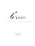
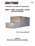
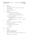
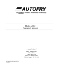
Operators Manual Operation, Maintenance and Service Halton Hoods with Water Wash Model: KVE-WW, KVC-WW, KEO & KEP GENERAL DESCRIPTION All Halton Capture Jet® hood systems provide solutions for a variety of commercial foodservice ventilation applications over virtually any cooking process. Halton’s Capture Jet® technology gives the most efficient system on the market. To achieve the optimum performance from your hood system (s) please use the following guidelines provided within the pages of this Installation, Operation, and Maintenance Manual. In addition to this information our offices or local representatives are available at any time to provide additional technical support for products, applications, installation, commissioning or in any aspect that you may have. RECOMMENDATION Upon receipt of the Halton hood (s), inspect unit (s) immediately for any shipping damage and notify carrier immediately if damage is found. Halton will not accept responsibility for any shipping damage. All systems are thoroughly inspected before leaving our factories, however Halton will assist in filing a claim if needed. GENERAL INSTALLATION It is the responsibility of the installing contractor to see that the system installation is completed in accordance with the project plans and specifications and that it meets all specific requirements of local code officials. The local authority having jurisdiction could over rule some of the installation details written in this manual. The installation shall be in accordance with NFPA-96 and ULC S650. All components of this ventilation system shall be installed in accordance with the instructions found below in the section titled “Installation Instructions”. These canopy hoods must be sized to completely cover the equipment it is designed to ventilate. The distance between the floor and the lower edge of these canopy hoods shall not be less than 78” (2000 mm). All electrical systems shall be installed following local and national codes. The owner and/or operator should be instructed in the proper operation, care and maintenance of the system. If questions or complications should arise during the installation of the Halton hood (s) that cannot be solved using the instructions provided please contact the Halton office. Halton Company, USA 1-800-442-5866, or Halton Indoor Climate Systems, Canada 1-800-565-2981. Note: There are no instructions contained within this manual for installation or maintenance of fan packages. **See appropriate manufacturers manual for detailed instructions. EXHAUST AIRFLOWS Halton Hoods with Water Wash Operation & Maintenance & Service Manual 2 CJOWWM/012009/rev1/EN Because the listed exhaust airflows rates were established under controlled laboratory conditions, please see submittal drawings or contact the manufacturer for exhaust air flow rates. INSTALLATION INSTRUCTIONS 1. Inspect the crating carefully. If there are signs of damage, call the freight carrier before uncrating the units. Carefully uncrate the units. Check all local codes prior to installation, special requirements may be necessary depending on local building material construction. ** Important note ** Do not leave unit (s) exposed to extreme temperatures for an extended period of time, this may cause the protective PVC coating around the unit (s) to become very difficult to remove. 2. Position the hood near the actual installation site. In case of multiple hoods, check the engineered set of drawings for locations. Pay close attention to collar sizes and fire protection layouts, matching the hood systems to the correct location shown on the drawings provided. **Check item numbers on crates / hoods vs. drawing item numbers. 3. Once the hood is carefully removed from the shipping crate and set in position, the unit is now ready for installation. If Halton Company has supplied a backsplash assembly, then the splash assembly should be installed first, for installation procedures. (See pg. 5) 4. Hang the hood using ½” threaded rods by attaching the rods to the hood through the hanger brackets that are welded to the top of the hood. Use of turnbuckles will make final adjustment easier. Standard hanging height for canopy hoods ranges from 78” min. to 84” max. above the finished floor (per local codes having jurisdiction). **Noted in installation instructions - (see pg. 6). **All typical installations for Halton Water Wash Hoods including CJ series hoods shown on pages 15 and 16. 5. If Closure Panels are supplied by Halton (see pg. 9) for details on the installation. 6. For multiple hoods end to end, or back to back (see pg. 8) for Installation of Splice Strips and U-Channels. 7. For hoods equipped with a supply fire damper, it is very important to make sure that the fire damper is set in an open position before connecting the supply duct. For units with exhaust fire dampers, (see pg. 10), or supply fire dampers, (see pg. 10) for installation details. 8. Electrical circuits should be connected according to standard switch panel wiring diagram, shown on (pg. 11). For Halton Capture Jet® series hoods, a typical wiring diagram is shown on (pg. 13). 9. Grease filters and grease cups must be installed in place before start-up. 10. Install 100 watt maximum light bulbs in standard incandescent lights or fluorescent bulbs (36” L or 48”L) in fluorescent lights. **Note: Halton does not provide bulbs. Halton Hoods with Water Wash Operation & Maintenance & Service Manual 3 CJOWWM/012009/rev1/EN 11. Protect the hood from damage under normal job site conditions, until all work is complete and system is ready to be put into operation. OPERATION OF SYSTEM 1. After installation is complete, it will be necessary to check and balance the airflows. On the Capture Jet® line of hoods, Halton supplies T.A.B. (testing and balancing) ports for measuring the pressure drop. These ports are located on the inside of the canopy on each plenum. (Exhaust and Capture Jet®). For details on their use (see pg. 13). For hoods without ports, use of standard practices (duct traverse / average velocity / etc) for measuring airflows will be required. **It is very important that the fan for the Capture Jet® air be balanced according to specifications. See the job specific information for required airflows. Adjustments to the Capture Jet® fan can be made with the speed controller supplied with the fan. This speed controller will be mounted inside or on top of the hood, or mounted in an electrical enclosure. Information regarding the fan and speed controller (see pg. 13). 2. Each Halton Capture Jet® hood system will have a “KSA” filter remover (model KFR). The “KFR” will be packaged separately, inside the hood, the box will be labeled “Attn: Kitchen Mgr. “ Model KFR instructions on (pg. 5). The KFR will assist in removal of the filters for assembly and cleaning. 3. After the exhaust and supply airflows have been properly balanced, a final inspection should be made to ensure proper system operation. MAINTENANCE AND CARE INSTRUCTIONS You have purchased the finest exhaust hood equipment available anywhere. Like any fine piece of equipment, it should be given regular care and maintenance. Your new equipment should be serviced by an experienced service organization. Your Halton dealer is well qualified to coordinate this service. Periodic inspections are recommended to check the operation. When corresponding with factory or your equipment dealer regarding service or replacement parts, be sure to refer to the unit by the correct model number, including prefix and suffix letters and numbers and serial number if shown. The model plate is affixed to the unit contains this information. REGULAR MAINTENANCE ENSURES PEAK PERFORMANCE Cleaning Exterior STAINLESS STEEL - Normal soil may be removed with Halton G-Wiz detergent and warm water applied with a cloth. NOTE: Remove grease build-up from fixed baffles and other interior surfaces. FIRE SYSTEM COMPONENTS Fire system components should be inspected and cleaned during routine duct maintenance. Halton Hoods with Water Wash Operation & Maintenance & Service Manual 4 CJOWWM/012009/rev1/EN Fusible links should be replaced annually. Certificates of inspection and maintenance shall be provide to the owner and a copy displayed on the premises. HALTON WATER WASH HOODS Daily: Clean exhaust hood exterior. See Cleaning Exterior. Monthly: Inspect the primary grease extractor. It if it observed that the KSA grease extractors developed excesses grease build-up due to low water pressure or low detergent, it may be necessary to remove the filter baffle to remove the KSA grease extractors. With the KSA’s removed, run them through a dishwasher or soak them in a hot sink with detergent. The filter removal tool is used to remove the KSA filters as instructed below. KSA FILTER REMOVAL WITH MODEL KFR S.S. Coupling S.S. Pipe 16 ga. S.S. Bracket To assemble the KFR filter remover: Screw together stainless steel pipe, coupling, and bracket and tighten all joints. (as shown in above picture) To remove filter: Filter Installation and Removal Insert bracket into the inside KSA filter slots, and lift upward until filter slides out of plenum. To install filter: To remove filter *** It is very Important to lock top lip of filter in place in installation as shown in reference drawing. Halton Hoods with Water Wash Operation & Maintenance & Service Manual 5 To install filter CJOWWM/012009/rev1/EN Place filter on KFR (filter removal tool) bracket, raise filter into place inside exhaust plenum. Slide upward until top lip of filter is locked into place and bottom lip of filter slides in place inside the exhaust plenum. 1” Insulated Backsplash Assembly Screw through top of flange to wall. *( screw head will not interfere with hood) Screw backsplash to wall or attach with adhesive. Halton Hoods with Water Wash Operation & Maintenance & Service Manual Flat Sheet Backsplash Assembly 6 CJOWWM/012009/rev1/EN Halton canopy hoods should be installed from 78” min.- 84” max. above the finished floor. Typical Hood Installation Details *Optional Unistrut / Turn Buckle Detail Hanger Bracket / Turn Buckle Detail Welded to top of hood. 18 ga. material All Thread (By Others) Standard hanging height is 78” minimum to 84” maximum above the finished floor. Halton Hoods with Water Wash Operation & Maintenance & Service Manual 7 CJOWWM/012009/rev1/EN Hang the hood using 1/2” threaded rods by attaching the rods to the hood through the hanger brackets (as shown) which are welded to the top of the hood, using the turnbuckles will make final adjustments easier. Hanging height of Canopy hoods should be per local building codes, verify with “Authority Having Jurisdiction” for hanging height in your project location. Recommended Exhaust Duct Installation Details Exhaust Duct Options Available (liquid tight external weld) Exhaust Duct per code Supply Duct Supply Duct Screws or Rivets are not to interfere with the operation of the fire damper (if equipped). Halton Hoods with Water Wash Operation & Maintenance & Service Manual 8 CJOWWM/012009/rev1/EN Supply Duct may be attached to supply collar with sheet metal screws or pop rivets and sealed with duct tape. Splice Strip / U-Channel Assemblies Hoods shown back to back Fig. 1 B B Splice Strip A U-Channel Installation Notes: U-Channel: For hood models that are placed back to back (as shown in Fig. 1): Slide the U-Channel A up over the back of the hood systems, and secure with sheet metal screws. For hood models that are placed end to end (as shown in Fig. 2): Pry apart the U-Channel at one end and slide over the end panels, fastening in place, fitting around the perimeter of the hood systems. A Splice Strip: For hoods placed back to back: Slide Splice Strip B over bottom of hoods first, then over top, secure by welding together. For hoods placed end to end: Slide over bottom front edge first then over top, secure by welding together, or as an option using screws for models with supply plenum. B Splice Strip Hoods shown end to end U-Channel Fig. 2 A A Halton Hoods with Water Wash Operation & Maintenance & Service Manual 9 CJOWWM/012009/rev1/EN B Closure Panel Assembly D E C B C A B Installation Notes: 1) Panels “A” and “B” are to set on top of the hood perimeter. *Vertical flange at the bottom of closure panel and vertical flange on top of hood should line up. 2) Hammer clips “C” over the two vertical flanges. 3) Attach panels “B” to wall using appropriate hardware “D”. 4) Slide front panel “A” into place. Halton Hoods with Water Wash Operation & Maintenance & Service Manual 10 CJOWWM/012009/rev1/EN 5) Attach panels “A” and “B” together using hardware “E” *(Hardware not provided by Halton) Exhaust Fire Damper Assembly Optional in Models : KVE / KVC 1. Remove grease filters. 2. Uncoil Stainless Steel cable attached at clip (A) 3. Thread end of cable from eyebolt at clip (A) going through eyebolt at clip (B), then thread through eyebolt at clip (C). 4. Hold fire damper in maximum open position to attach “S” hooks at point (D), close “S” hooks to secure. 5. For final adjustment of fire damper, tighten eye bolts at clips (A), (B) and (C) so that cable has no slack, and assure maximum open position is obtained. ** (Access to fire protection exhaust duct nozzle to be provided by others) ** Fire Damper, Fire Resistance Rating 1.5 Hr, Fusible Link Rating 286F The collar is supported by a 1/2” flange located on the inside perimeter of the damper. Secure “S” hook to damper as shown. Eye bolt Fusable Link **Located in below detail as (D). Clip (B) D Clip (A) Halton Hoods with Water Wash Operation & Maintenance & Service Manual 11 CJOWWM/012009/rev1/EN Clip (C) Standard Switch Panel Wiring *(For Hoods not equipped with Capture Jet) Halton Hoods with Water Wash Operation & Maintenance & Service Manual 12 Wires Numbered as shown in junction box. CJOWWM/012009/rev1/EN - #5 ---- ---- ---- ---- ----- By Electrician ------------------------------ By Halton Capture Jet Fan Installation ® Integrated Capture Jet® fan (Optional) (Standard) KSA Filter T.A.B. Ports Speed Controller Models KVE, KVC are equipped with an Integrated Capture Jet fan package, as shown above. Typical Wiring of Capture Jet® Fan Halton Hoods with Water Wash Operation & Maintenance & Service Manual 13 CJOWWM/012009/rev1/EN w/ Halton supplied Switch Panel T.A.B.™ - Testing and Balancing Ports Exhaust T.A.B. Readings vs. Airflow T.A.B. Port Readings 0.35 Hood Model KVE/KVC Design T.A.B. (inches WC) 0.20 0.30 T.A.B. Reading (In. WC) Capture Jet® This example shows how to determine the correct T.A.B. port reading for the exhaust hoods. 0.25 0.20 0.15 0.10 0.05 0.00 800 1050 1300 1550 1800 2050 2300 Airflow (cfm) In this example, a design airflow of 1700 cfm is selected from the Airflow axis, and a vertical line is drawn up to the T.A.B. pressure curve for this hood. Measured Pressure A horizontal line is then drawn for the T.A.B. pressure curve to the T.A.B. reading axis on the left-hand side of the chart and the corresponding pressure is read off the chart as 0.19 inches of Water Column. The Capture Jet ® and exhaust air flows are easily and accurately determined by measuring the pressure difference from the T.A.B. (Testing and Balancing) ports mounted in each plenum. The corresponding air flows can be read from the diagram provided. Closeup view of T.A.B. Port ****For accurate results, the balance contractor should receive a copy of the job specific hood plans with the design T.A.B. readings from the hood supplier prior to balancing. Halton Hoods with Water Wash Operation & Maintenance & Service Manual 14 CJOWWM/012009/rev1/EN **** It is very important the cooking equipment is in operation to create a thermal plume, prior to the air balancer, to be able to use the T.A.B. ports. Model KVE-WW Typical Installation UL listed upblast fan for restaurant cooking appliances 40 “ min. 16 ga. duct work all welded per code **Incandescent or Fluorescent lighting available. Standard Capture Jet® intake location **(optional top mounted Capture Jet intake also available) KSA Filters Capture Jet® Airflow 78”-84” A.F.F. Standard Halton Hoods with Water Wash Operation & Maintenance & Service Manual 15 CJOWWM/012009/rev1/EN **(Verify with Authority in project location for min. hanging height) Model KVC-WW Typical Installation 120” min. 40” min. Filtered MUA unit on the roof 16 ga. duct work all welded per code Stainless Steel KSA filters Make-up airflow Capture Jet® air 78” - 84” A.F.F. 78” Std. Halton Hoods with Water Wash Operation & Maintenance & Service Manual 16 CJOWWM/012009/rev1/EN **(Verify with Authority in project location for min. hanging height) Halton Hoods with Water Wash Operation & Maintenance & Service Manual 17 CJOWWM/012009/rev1/EN Model KEO & KEP Typical Installation Features • 120V, single phase, 60 Hz. • Microprocessor based, versatile, user friendly and easy in the field programmable. • One control panel required per exhaust fan regardless on number of Water Wash hoods, but it can drive multiple fans if required. • Controls exhaust fan and make-up air fan. • Controls cold water/hot water. • Either local or remote AUTO/WASH/RUN operation, mater - slave configuration for multiple panels • Remote system status monitoring, customizes error signal to meet requirements. • Digital text display and light indicator to monitor system status. • Adjustable washing cycle by simple procedure at the panel. • Fire alarm. • Low detergent level. • Size 28” x 34” x 7”. Halton Hoods with Water Wash Operation & Maintenance & Service Manual 18 CJOWWM/012009/rev1/EN when required. CONTROL PANEL COMPONENT FUNCTIONS Water Shut Off Valves: There are two water shut off valves on both the hot and cold water lines, so that the components in both hot and cold water lines can be isolated for easy removal. Pressure Reducing Valves: These valves are located in the hot and cold water lines to reduce the operating pressure to 25 PSI (172 kPa). Solenoid Valves: There is a solenoid valve in both the hot and cold water lines to automatically control the water flow. Detergent Pump: This pump is used to inject a controlled amount of the detergent into the hot water line when in wash mode. Fuse Block & Terminal Strip: To provide a 5 amp fuse to to protect the electrical components in the control panel. Cold Water Pressure Gauge: This gauge is used to check the cold water pressure on the outlet side of the pressure reducing valve. Should read 25 PSI (138 kPa) while in operation. Plug Hot Water Line: This plug can be removed and a pressure gauge or thermometer screwed inot the hole for field termperature and pressure reading. Cold Water and Hot Water Strainers: The strainers located in the PRV valve are used to strain out dirt from the water flow and to protect the solenoid valves and water nozzles from plugging up. Detergent PUmp Check Valves: This valve stops the detergent in the pump and tube from draining back down into the detergent tank when the pump is not in operation, eliminating the need to continually prime the pump. PLC Siemens: Controls all functions of the panel. The PLC takes care of alarms as well. Display - TD200: Displays all messages, for system operation and alarms in the system. METHODS OF MOUNTING CONTROL PANEL Location of control panel is determined by the kitchen equipment contractor. The recommended mounting height above the finished floor and type (recessed or surface) is indicated on the show drawing. RECESSED CONTROL PANEL Recessed mounted models. The panel can be shipped early to allow cabinet to be built into wall. Fastening as per surface mount units. SURFACE MOUNT CONTROL PANEL Surface mounted models are shipped as complete units. The installer must drill holes in the back of the cabinet and com- Halton Hoods with Water Wash Operation & Maintenance & Service Manual 19 CJOWWM/012009/rev1/EN ponents plate to suire wall structure and securely fasten pabel to wall with lag or butterfly bolts. CONTROL PANEL OPERATION The Water Wash control panel is designed to operate Halton Water Wash hoods. If an alarm goes off on the panel it indicates then there is a problem. To silence the alarm, press the “MUTE” button; however, the indicator lamps will remain lit. DISPLAY CAUSE SOLUTION Low Level Detergent Low level of detergent in the tank. - Refill detergent Fire The fire system has been activated. STANDARD CONTROL PANEL - For more sequences dimensions of control panel will change. - If 5 gallon option used length will change from 28” to 40” Halton Hoods with Water Wash Operation & Maintenance & Service Manual 20 CJOWWM/012009/rev1/EN Notes: CONTROL PANEL - INPUT - OUTPUT DESCRIPTION Fire Switch – Normally Open contract of fire relay in any fire suppression system (for example Ansul) switch connected to terminals 8 and 10 • When switch is closed, gives signal to control panel and notifies that system is on fire. • Alarm lamp(red color)lit and display shows FIRE • Exhaust and Makeup fans may be shut off (depending on internal programming) • This particular alarm remains active even when unit is in Off position • MUA fan must be interlocked with exhaust fan. Remote AUTO/WASH/RUN switch Used to remotely turn the system in RUN and WASH • If remote control for the panel is needed, this switch is on AUTO position • This enables panel to be controlled from external or internal time clock, BMS or similar systems. OUTPUTS Exhaust Fan – terminals 1 and N. AC voltage to energize exhaust fan starter,120 VAC. Makeup Fan – terminals 2 and N. AC voltage to energize makeup fan starter,120 VAC. Cold Water Solenoid - terminal Q0.7 and N Alarm signal output – Terminal numbers to be assigned. Dry contacts which close/open on certain alarms can be provided to send signal to remote monitoring system. Halton Hoods with Water Wash Operation & Maintenance & Service Manual 21 CJOWWM/012009/rev1/EN Hot Water Solenoid - terminal Q1.0 and N FRONT PANEL APPEARANCE • Green light –“System OK” indicates when system is in normal operating mode and no alarms are occurring. • Red light –“Alarm” indicates when there is a failure appearing in the system • TD 200 Siemens display ( text display )- shows text messages (displayed in two rows) system status • Soft touch buttons on the display( square shape –located bellow messaging display): • Wash time button to set the time for washing cycle (second button from left) - For 1 SQ. • Wash time button to set the time for washing cycle (third button from left) - For 2 SQ. • Wash time button to set the time for washing cycle (shift & second button from left) - For 3 SQ. • Wash time button to set the time for washing cycle (shift & third button from left) - For 4 SQ. Halton Hoods with Water Wash Operation & Maintenance & Service Manual 22 CJOWWM/012009/rev1/EN There are two indicator lights located at the top of the panel: OPERATING MODES - SEQUENCE OF OPERATION OFF MODE • The unit displays WASH DONE STAND BY • All outputs are off • Indicator light “System OK” is lit. System is ready to be started again. • Statistics can be consulted/cleared using appropriate keys RUN MODE • Put selector switch ”RUN/WASH” in RUN position • The unit displays SYSTEM ON FAN ON first row • The unit displays COLD WATER MIST ON second row (if applicable, for HC5-25) • Exhaust fan is on • Make up air fan is on • Cold water solenoid on • Statistics can be consulted/cleared using appropriate keys WASH MODE • Select RUN/WASH switch in WASH position-turn off sequence is as follows: • The unit displays WASH ON 60 SEC DELAY • Exhaust fan is off • Make up air fan is off • Washing cycle is delayed for 60 seconds allowance for fan to stop. Automatically after 60 seconds of delay panel is going to washing cycle : • The unit displays WASH ON_____MIN • The display is showing the current time on washing hoods. • The hot water solenoid is on • Detergent pump is on • Washing cycle finishes after preset time ( by default 3 min)-this is adjustable by wash time setting button After the first wash cycle finishes by program the system automatically shuts down in stand by. If the panel has more than 1 sequence 2,3 and 4 will start automatically once the previous sequence is completed. • The hot water solenoid is on • The unit displays WASH DONE STAND BY Halton Hoods with Water Wash Operation & Maintenance & Service Manual 23 CJOWWM/012009/rev1/EN This message will persist until operator put the selector switch in RUN. VIEWING/CLEARING STATISTICS • Statistic can be cleared by pressing the Mute key while pressing the statistic key. • Wash time can be changed easily by a simple procedure 1. Press “WASH TIME SETTING” button on the electronic text display. Currently set value in minutes is displayed. 2. Press the “ENTER” button, a blinking cursor appears 3. Use the “” up and down arrows to set desired wash time. 4. Press “ENTER” again to finish. FACTORY DEFAULT VALUES: The unit has pre programmed default values FAN OPERATION DURING FIRE Halton Hoods with Water Wash Operation & Maintenance & Service Manual 24 CJOWWM/012009/rev1/EN When the unit detects the Fire input, it will shut off the make air fan. The exhaust fan will remain on by default according to this parameter. Exhaust fan must remain on after fire suppression has been activated. MUA will remain off. Fuel source to appliances, gas and or electric, shall be shut off by either automatic valve and/or shunt trip breaker as appropriate based on signal from fire system. Halton Hoods with Water Wash Operation & Maintenance & Service Manual 25 CJOWWM/012009/rev1/EN FIELD WIRING DIAGRAM ELECTRICAL WIRING/CONNECTIONS Two electrical wiring diagrams are shown below: 1) Control Panel electrical wiring diagram FIELD WIRING BY OTHERS AIR MAKE-UP FAN EXHAUST FAN 2) Field wiring diagram 120 VAC, 60 Hz UNINTERRUPTED POWER SUPPLY G N N N N N N L N L R1 5A 14 H.W. SOL. R DETERGENT PUMP 12 BUZZER G C.W. SOL. FIRE RELAY 11 A1 A2 3 120V 0.0 1L 0.2 0.1 0.3 2L 1 2 0.4 0.5 1A 4 0.6 3L 0.7 1.0 1.1 1.1 1.2 1.3 1.4 N L1AC M L+ CPU 224 SIEMENS S7-200 TD-200 0.0 0.1 0.2 6 8 C N.O. FIRE SWITCH C RUN / WASH NC NO 5 0.3 8 0.4 0.5 0.6 0.7 2M 1.0 1.5 7 DETERGENT SWITCH C NC 1M 8 Halton Hoods with Water Wash Operation & Maintenance & Service Manual 26 CJOWWM/012009/rev1/EN HC5-25-EFO-S WIRING DIAGRAM INOPERATIVE PROBLEM CAUSE SOLUTION Exhaust fan will not function Field Wiring Breaker or Burned Contactor - Verify field wiring for proper connections - Check fuse at control panel - Change Contactor - Plunger Stuck - Coil Burned - Change Solenoid Solenoid will not function Halton Hoods with Water Wash Operation & Maintenance & Service Manual 27 CJOWWM/012009/rev1/EN TROUBLE SHOOTING GUIDE WARRANTY ACTIVATION FORM This form must be completed and returned to Halton in order for your warranty to be valid. Job & Location Information: Job Name: Street Name: City: State: Zip Code: Equipment Start-Up Date: Product Serial Numbers: Contact Information: Contact Name: Title: Chef, Kitchen Mgr/Facilitly Mgr/Property Mgr/ etc. Facility Management Company Name (if applicable): Email: Phone Number: Cell Number: Submit by Email Please use the "Submit by Email" button to submit this form electronically or: Fax completed form to: Halton Company Attention: Service Department 1-800-442-5866 www.haltoncompany.com Halton Hoods with Water Wash Operation & Maintenance & Service Manual 28 CJOWWM/012009/rev1/EN Fax: (270) 237-5700 HALTON LIMITED WARRANTY Halton (“Manufacturer”). Warrants only to its direct purchasers and to no others, that all products manufactured by the Manufacturer shall be free from defect in materials and workmanship for a period of twelve (12) months from the date of the original installation and start-up or eighteen (18) months from date of shipment, whichever occurs first. All products sold but not manufactured by Manufacturer will be warranted for a period of twelve (12) months from date of shipment. (Halton’s Warranty Card must be completely filled out and returned to Halton within 3 weeks after the equipment start-up date for your warranty to be valid *IMPORTANT NOTE: “IF” this form is returned within the specified timeframe, Halton will extend your standard warranty by 120 days.) For products manufactured by the Manufacturer we agree to pay any reasonable labor costs necessary to repair or replace, at Manufacturers option, defective parts or materials for a period of twelve (12) months from date of original installation and start-up or eighteen (18) months from date of shipment, whichever occurs first. All labor costs subject hereto shall be performed during standard work hours at straight-time rates. For products sold but not manufactured by the Manufacturer we agree to pay any reasonable labor costs necessary to repair or replace, at Manufacturers option, defective parts or materials for a period of (90) days from date of original installation and start-up or (12) months from date of shipment, whichever occurs first. All labor costs subject hereto shall be performed during standard work hours at straighttime rates. Purchaser shall pay incurred premium labor charge, including overtime, weekends and holidays. Travel time, service charges, miscellaneous tools, material charges, and labor charges resulting from inaccessibility of equipment will not be paid by Manufacturer. This LIMITED WARRANTY SHALL APPLY ONLY to products that have been installed and maintained in accordance with the installation and Care Instruction Manuals. Purchaser shall be solely responsible for adhering to the instructions and procedures set forth in the said instruction manuals. This LIMITED WARRANTY SHALL NOT BE APPLICABLE to any damage or defect resulting from fire, flood, freezing or any Act of God, abuse, misuse, accident, neglect or failure to adhere to all instructions set forth in the installation and Care Instruction Manuals. Furthermore, this limited warranty shall not apply to any product that has been altered, unless such alteration has been approved in writing by a duly authorized representative of the manufacturer. In no event shall the manufacturer be liable for any loss, expense, personal injury or consequential damage, of any kind or character, as may result from a defect in material, and/or workmanship, however caused. EXCEPT AS IS EXPRESSLY SET FORTH IN THIS LIMITED WARRANTY, MANUFACTURER MAKES NO WARRANTY OF MARKETABILITY FOR FITNESS OR ANY PARTICULAR PURPOSE. NEITHER DOES MANUFACTURER MAKE ANY WARRANTY, EXPRESSED OR IMPLIED, WITH RESPECT TO PRODUCTS SOLD BY MANUFACTURER OR AS TO THE USE THEREOF. Halton Company 101 Industrial Drive, Scottsville, 42164 USA Tel: 270-237-5600 Fax: 270-237-5700 Website address www.haltoncompany.com Halton Indoor Climate Systems, Ltd. 1021 Brevik Place • Mississauga, ON L4W 3R7 CANADA Tel: 905-624-0301 Fax: 905-624-0301 Website address www.haltoncanada.com