1
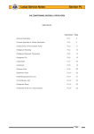
Section
2-6
Quality People - Quality Products
Service Instructions
Mesabi Copper Tube
Radiators and Air to Air Coolers (CAC)
Allied Systems Co. reserves the right to make changes to new equipment without incurring the obligation to make such changes to equipment previously manufactured.
80-967, REV. 6/2014
1
Standard Parts of a Typical MESABI Radiator Core
®
SINGLE UPSET TUBE
Additional
Tube Styles
Exploded view of a typical
MESABI® water jacket core
(Sold As Assemblies Only)
PART
NO.
DESCRIPTION
TOP HEADER PLATE (bolted design) ............ ...... refer to parts page
TOP RUBBER SEAL .............................................. refer to parts page
TOP FELT AIR BAFFLE ......................................... refer to parts page
BREAKER TOOL.................................................................... 226672
(for freeing tubes from rubber seal)
RUBBER TUBE STAY.................................................... ‘F’
(for staggered MESABI Cores only) ........................ ‘H’
227263
226668
RUBBER TUBE STAY END PIECE .............................. ‘F’
(for staggered cores only) ........................................ ‘H’
252917
226669
BOTTOM FELT AIR BAFFLE ................................. refer to parts page
ITS™
(Individual
Tube
Support)
Used on
H, L, and
V style
cores
RUBBER SEAL – LOCKING GROOVE ................. refer to parts page
BOTTOM HEADER PLATE (bolted design) ........... refer to parts page
RUBBER PLUG ...................................................................... 226670
Note: Plugs are for temporary plugging of ferrule
holes until replacement tubes can be installed.
Plugs must be installed dry and are not
recommended for systems operating over 15 P.S.I.
INSTALLATION TOOL ........................................................... 226671
(for removing and installing tubes)
STAY
Used on
“L” style
cores
ITS Tube
Installation Tool
P/N 252922
(See page 5,
TM
Figure 8)
HEADER PLATE HOLE
CLEANING BRUSH – P/N 259069
STAY
Used on
“M” style
cores
SEAL AND TUBE END
LUBE BRUSH – P/N 252920
LOCKING
GROOVE SEAL
must be used
at the bottom. The
tube bead will seat
in the seal inner
groove.
Tube Locking design
2
Bottom Plate
STAY
Used on
“V” style
cores
Quality People - Quality Products
Cleaning
Tube Removal
STANDARD EXTERNAL CLEANING
HELPFUL HINTS:
To maintain efficiency and assure maximum life of
a MESABI ® Core, reasonable care must be taken when
cleaning.
Most radiator shops use a hot alkaline soap, caustic
soda or chemical additives in their boil-out tanks, which
attacks solders. If a MESABI ® tube is soaked in such a
solution, the solder bond between the finning and tube
will be adversely affected. If it is known that the particular
solution used is not harmful to solder, then it will not
hurt the solder used on the MESABI ® tube. Be sure to
completely rinse the cleaned tube/core in clean water
after removing from the boil-out tank.
In most cases, it may be best to blow out any dry dirt
with a high pressure air gun prior to washing the core
with a high pressure hot water washer.
For general external cleaning, a high pressure, hot
water washer (with or without soap) can be used at
pressures up to 1200 psi (8274 KPa). (CAUTION! To
prevent fin deformation, you must stay a few inches
away from the core and spray straight into the core
not at an angle. If the cooler is still in the machine,
you may have to use an offset angled nozzle so that
you can spray straight into the core. If there is any
doubt, try your cleaning method on a small portion of
the core first.) It is important to start on the air exit side.
Work from the top to the bottom. Concentrate on small
areas and work slowly. Wash until the water exiting the
opposite side is free from dirt and debris. Complete this
side and then repeat the process from the other side.
• Clean the core prior to removing tubes.
• To avoid bending or kinking tube ends, reduce the
angle of the tube as it’s being pulled from the top seal.
• If the core has a center tank, remove the top core
tubes and seals first.
• If the core has an ITS™ (Individual Tube Support) or
stay system with support bars, mark the bars front
and back before removing, to ease reassembly.
• To assist in the removal process, spray WD-40 on
the top end of tubes.
• If tubes are difficult to remove, try using the breaker
tool and removal tool simultaneously.
STEP 1.
Loosen the tube by using Breaker Tool, Allied P/N
226672, as shown in Fig. 1. The Breaker Tool should
be placed at top or bottom, not at middle when freeing
tube from seal. Lightly twist the tube back and forth,
to loosen tube from seals.
Fig. 1
EPOXY-COATED CORES
Epoxy-coated cores must be cleaned with care to
assure the coating is not damaged.
1. A high pressure hot water washer can normally
be used. Use a “fresh” water supply. Water
temperature should not exceed 1800F. Do not
steam clean. The nozzle should be kept
approximately 12 inches away from the core.
CAUTION! We do not recommend a pressure rating
because as epoxy ages the coating does become
brittle and might be damaged at higher pressures.
We recommend that you try your cleaning method
on a portion of a single tube first.
2. Wash the core thoroughly and methodically,
starting at the top and working towards the
bottom. Do not wash in one area for extended
periods. The core will be clean when the water
exiting the core is clean.
3. Blow off excess water with air.
Epoxy coatings are not meant for submergent duty.
L&M Radiator does not warrant against corrosion, but
this coating, properly cared for, will help increase the
service life and efficiency of your cooling system.
STEP 2.
After tube is free, place upper jaw of Installation Tool
P/N 226671 around the round portion of tube, just below
the flattened portion. Place lower jaw on top of bottom
seal, see Fig. 2. Squeeze handles of tool together and
raise tube only enough to clear bottom seal.
Fig. 2
INTERNAL CLEANING
In most cases just flushing the inside of the tubes with
a high pressure hot water washer, with soap, will do the
job. Rinse thoroughly with clean water.
3
Tube Removal (continued)
STEP 3.
Put down tool and swing tube out just far enough
to allow it to be pulled down and out of its top seal, as
shown in Fig. 3.
Remove all tubes in the row, repeating the above
procedure.
Fig. 3
If you are working with any of L&M’s ITS™ or stay
systems with interlocking tabs, the tube must be raised
high enough so that the interlocking tab clears the
adjacent groove, as shown in Fig. 4.
Fig. 4
Seal Installation
HELPFUL HINTS:
• L&M recommends installing new MESABI ®
seals when tubes are removed.
• After removing the old seals, clean the plate holes of
any foreign debris with Allied P/N 259069 header plate
hole cleaning brush placed in an electric or air drill.
• Clean out inside of tanks and blow out plate
holes with air.
• Install new seals in clean dry holes. Do not apply any
lubricant to header plate holes.
• If the core has a center tank, do not install
seals at the bottom of the top core until all the
tubes are installed in the bottom core.
• For ease of seal installation, soak seals in hot
water just prior to installing.
• Make sure you use proper seal part number (see your
parts manual).
With your thumb, start the new MESABI ® seals into the
holes and push them part way in. Care must be taken not
to install seals too far into the header plate. A properly
installed seal has a crowned or convex top surface, and
the tube hole is slightly flared at the opening. A seal that
is installed too far into the header has a concave top
surface and the tube hole is noticeably smaller in
diameter as shown in Fig. 5. Over-installed seals will
make tube installation more difficult and are much more
likely to be damaged during tube installation.
The use of a hammer directly on the seal can easily
cause seals to be installed too far into the header plate.
L&M recommends the use of a flat plate 3/8” x 3”x 6”
placed over the seals. Hitting with a rubber mallet
will allow the seals to be properly installed.
Fig. 5
ON THE LEFT:
Properly installed
seal.
RIGHT:
Cleaning Tube Ends
Before the original tubes are reinstalled, the
tube ends must be clean of foreign material. L&M
recommends polishing the tube ends with a polishing
wheel (Grainger #5A725 – use Qty. 5 together) and a
copper polishing compound (Grainger #3W769).
If the debris cannot be removed by polishing, L&M
recommends using a piece of fine grit emery cloth or
steel wool. If there is a lot of debris on the tube ends,
use a 6” or 8” diameter wire wheel brush with a wire
size of .006 or .008. Larger diameter wire sizes could
damage the tube ends. Try installing a tube.
If it does not slide easily into the top and bottom
seals, try polishing the tube ends as per above.
4
Seal installed
too far into header.
CORRECT
INCORRECT
Lubricating Seals and Tube Ends
For ease of tube installation and to minimize the chance
of scuffing or tearing rubber seals during tube installation,
both top and bottom seals and both tube ends must be
thoroughly lubricated, (seals 226663 & 226664 use lube
P/N 252933, seals 250669 & 250690 use lube P/N 259070).
Using a 1/2” diameter brush (Allied P/N 252920) and a
minimal amount of lubricant, apply a thin film into each
seal hole and onto each tube end.
Quality People - Quality Products
Tube Installation
CAUTION! If a tube seems difficult to install into
a seal, STOP and figure out WHY! One of the
following reasons could be the answer.
1. A tube or seal with inadequate lubrication.
2. Improperly installed seal that could be pushed
too far into the header plate hole.
3. Damaged tube end.
4. Trying to insert the tube into the seal at too
steep of an angle.
5. Tube is not centered in seal.
NOTE: If, for any of the above reasons, a tube is
difficult to install, the seal should be removed and
inspected for any scuffing marks, tears, or cuts. If there
is any doubt, replace the seal.
HELPFUL HINTS:
• If you are working with a center tank core, the bottom
core must be assembled before the top core.
• Minimize the angle of the tube as it’s being
installed into the top seal.
• Make sure the tube is centered in the bottom seal
before any force is applied to pull or push into place.
• For ease of tube installation, install the tubes
behind the side member gussets in each row
first. Install the tubes behind the left side gussets,
working towards the core center. Then, going to
the far right hole, in the same row, install the tubes
working towards the core center.
• Individual rubber tube stays and, in some cases, tube
stay ends are necessary to interlock the tubes. For
part numbers see your parts manual . If more detailed
information is required for proper assembly of cores
using tube stays and tube stay ends, contact Allied
Systems Service Department at 503-625-2560.
• If your core style includes plastic tube supports, see
page 6 for ITS™ or stay orientation prior to starting.
STEP 1.
To minimize installation angle, tubes in any given row
must be installed from the closest header plate edge.
Use a minimum of angle and a slight twisting, pushing
motion, to push the top end of the tube into the top seal.
Push it far enough in so the bottom of the tube clears
the top of the bottom seal.
If you are working with any of L&M’s ITS™ or stay
systems, you will need to insert the tube far enough into
the top seal to allow clearance for the tabs to be aligned
with the grooves when the tube is pulled down into the
bottom seal (see Figs. 4. and 6.). Please note that when
ITS™ or stays with interlocking tabs and grooves are
present, the bottom end of the tube should be centered
in the seal and then pulled down slightly into the seal so
that the tabs engage the adjacent grooves.
NOTE: See page 6 for
ITS™ or stay orientation
in the core.
Fig. 6
STEP 2.
Center bottom end of
tube into respective seal
in the bottom header
plate. Then, push tube
down and into seal until the formed bead is seated into
the locking groove of the bottom seal.
This may be done by grasping tubes by hand and
pulling the tube downward until seated, or by using
Installation Tool,
Allied P/N 226671.
Fig. 7
This tool has
a semicircular
form on the end
of the handle.
Place this end
on the formed
bead of the
tube and push
downward
until seated, as
shown in Fig. 7.
Now, complete the row of tubes. Precaution should
be taken to make sure formed bead is seated into
bottom seal, and that the tubes are straight and aligned
to assure maximum air flow.
If you are working with an ITS™ system (refer to page
2 and page 6, Fig. 9, for identification), use Allied tube
installation tool P/N 252922 to pull the tube into the bottom
seal. (See Fig. 8.) Hook the slotted end of the tool behind
the front tab on the ITS™ tube support. Using the tool and
your free hand, center the bottom end of the tube into the
bottom seal. At the same time guide the dovetail slots into
the tabs on the ITS™ tube support. Once in place, and
with the tool P/N 252922 still hooked onto the ITS™ tube
support, pull the tube into the bottom seal until the formed
bead is seated into
the locking groove
of the bottom seal.
Fig. 8
Push the remaining
tubes in this row.
Use the same
procedure on all
remaining rows
except the front
side row.
5
Tube Installation (continued)
STEP 2. (CONTINUED)
Tube Support Orientation
All illustrations front side as viewed from top.
A. ITS™ (can be used on H, L, or V style cores)
Make sure the tabs on the ITS tube supports are facing
to the front and to the right.
Caution! To prevent seal leaks, do not allow the felt
baffles to be pushed (top) or pulled (bottom) into the
seal hole when installing the front row of tubes.
STEP 4. (If applicable)
If you are working with the ITS™ or stay support system,
install the appropriate support bar as shown in Fig.10.
Fig. 8
Fig. 9
Fig. 10
FRONT
B. “L” Stay
Fig. 9
FRONT
C. “M” Stay
PRESSURE TESTING
FRONT
D. “V” Stay
FRONT
NOTE: If you are working with an older stay style that
has rubber tube stays (see Exploded View page 3)
and need assembly assistance, please contact Allied
Systems Service Department at 503-625-2560.
STEP 3.
Before you install the front side row, install the felt air baffles.
6
The support bar part number has been stamped
on the outside face. Check your parts page for proper
installation. Using a rubber mallet, gently tap the bar into
place and secure to the side member.
Pressure testing procedure that follows recommends
10 test to pressure
testing to 15 psi (103 kPa). YouFig.
should
rating specified on tag attached to your cooler. If there
is no pressure rating specified, please contact Allied Systems
customer service with the part number of your cooler.
(Caution: Always bring air pressure up slowly and
always wear protective gear)
1. Pressurize with compressed air to 15 psi (103 kPa)
and submerge in water.
Fig. and/or
11
2. Seal any leaks at the test fittings
cover plates.
3. Repair any other leaks as needed.
4. Cycle test after successful initial test. Hold pressure at
15 psi (103 kPa) for 15 minutes. Note that the time starts
after all leaks are fixed and air bubbles have subsided.
Cycle to zero psi and pressure back up to 15 psi (103
kPa). Hold at 15 psi (103 kPa) for one minute. Repeat
three more times and then hold the last cycle pressure
at 15 psi (103 kPa) for five minutes. Should any leaks
appear, fix them, and start the cycle test over.
If you have any questions regarding the procedures
described in this Service Manual, please contact Allied
Systems Company at 503-625-2560 and ask for Customer
Service.