1
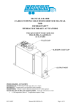
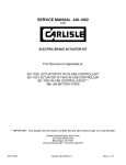
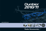
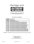
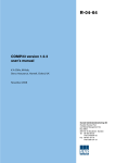
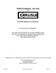
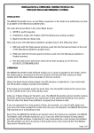
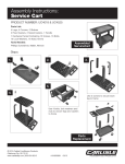
MANUAL 440-1008 CARLISLE SERVICE MANUAL FOR HYDRASTAR™ HYDRAULIC BRAKE ACTUATORS THIS DOCUMENT TO BE USED FOR HBA-10, HBA-12, and HBA-16 ACTUATORS FILLER CAP BLEEDER / DUST CAP OUTPUT PORT WIRE COLORS – FUNCTION SOLID BLACK – 25-40* amp 12 volt supply from tow vehicle SOLID BLUE – Output from in-cab electronic brake controller SOLID WHITE – Ground / must be directly connected to tow vehicle ground SOLID YELLOW OR BLUE W/ WHITE STRIPE – Cold side of breakaway switch * = Cold temperature (below 0° F) applications require 40 amp. ECN 04007 Manual 440-1008 Rev D Page 1 of 10 TABLE OF CONTENTS SECTION PAGE A. WARNINGS 2 B. ACTUATOR INSTALLATION INSTRUCTIONS 3 C. ELECTRICAL INSTALLATION REQUIREMENTS 4 D. TEST ELECTRICAL OPERATION 5 E. BLEEDING AND ADJUSTING THE BRAKES 6 F. TESTING & ADJUSTMENT OF ELECTRONIC CONTROLLER UNIT 7 G. REPLACEMENT PARTS LIST / MOUNTING DIMENSIONS 7 H. TROUBLE SHOOTING GUIDE 8 I. WARRANTY 10 A. WARNINGS PROPER INSTALLATION REQUIRED - The Hydrastar™ actuator must be installed by a qualified individual. Failure to properly install, protect, operate, and maintain the system can cause malfunction resulting in possible serious or fatal injuries and or property damage. MUST BE PROPERLY SIZED TO THE TOWED VEHICLE - The Hydrastar™ actuator is intended to provide flow and pressure to the brake system on the towed vehicle in accordance with applicable state and federal laws. It is the sole responsibility of the installer to see that the actuator is properly sized with the brake system on the towed vehicle so that the time required to build pressure in the towed vehicle brake system is not excessive. SELECT THE CORRECT OUTPUT PRESSURE - Over pressurizing the brakes on the trailer can cause permanent damage to the trailer brake system. It is the sole responsibility of the installer to determine the appropriate model of Hydrastar™ to insure that over pressurization of the trailer brake system does not occur. NOT INTENDED TO BE USED AS A PARKING BRAKE - The Hydrastar™ actuator and trailer brakes are intended only to supplement the service brake system on the towing vehicle. The Hydrastar™ actuator and trailer brakes are not designed to function as a park brake. At no time should the towed vehicle brake system be used as the primary source of braking for the towing vehicle. REQUIRES AN IN-CAB ELECTRONIC BRAKE CONTROL – The Hydrastar™ actuator is intended to be used with an in-cab electronic brake controller. The unit will operate with a wide variety of controllers but provides optimum performance when used with a CARLISLE electronic brake controller. Contact your dealer for a list of approved brake controllers. The list is also available online at www.carlislebrake.com The in-cab controller must have an output capacity of at least 5 amps for proper operation of the Hydrastar™ actuator. EXTENDED STOPS CAN GENERATE EXCESSIVE HEAT - When stopped for extended periods (i.e. such as at railroad crossings and traffic jams), apply the park brake on the towing vehicle and release the service brake pedal so that the Hydrastar™ actuator does not run continuously. Failure to follow this guideline will cause the Hydrastar™ unit to overheat and will damage the Hydrastar™ unit. EMERGENCY BREAKAWAY BATTERY MUST BE CHARGED - Do not attempt to tow the towed vehicle unless the emergency breakaway battery is fully charged. DO NOT POWER WASH THE HYDRASTAR™ UNIT - Although the Hydrastar™ unit is weather tight, it is not designed to withstand the direct high pressure spray from a power / car wash. Care should be taken to protect the Hydrastar™ unit from direct spray when washing the trailer. ECN 04007 Manual 440-1008 Rev D Page 2 of 10 B. ACTUATOR INSTALLATION INSTRUCTIONS ! CAUTION – Wheels must be properly blocked to prevent the trailer and tow vehicle from rolling. GETTING STARTED: 1. The following materials are required to properly install the Hydrastar™ unit: • If your trailer is not already equipped with brake lines, you will need enough 3/16” diameter automotive brake line to connect the trailer brakes to the Hydrastar™ unit. (Note that ¼ “ diameter brake line will improve response time.) Where possible, steel tubing is preferred. • 4 pieces of #10 mounting hardware to mount the Hydrastar™ unit to the trailer • ( 1 ) quart of DOT 3 or DOT 4 brake fluid (from a new, sealed container) • ( 1 ) emergency breakaway kit - must include a 12 volt, 5 amp hour (minimum) battery • Wire (see Section C. ELECTRICAL INSTALLATION REQUIREMENTS for proper wire size) LOCATION of the Hydrastar™ actuator is at the discretion of the vehicle owner. When determining location, consideration should be given to the following: 1. The shorter the brake lines are between the Hydrastar™ unit and the trailer brakes, the faster the brakes on the trailer will respond. 2. The unit should be located so that the electrical wiring and brake lines can be neatly routed directly to the towing vehicle and trailer brakes. Special care should be taken to minimize the number of bends and fittings in the brake line circuits. 3. An emergency breakaway kit must be located on the trailer so that the trailer breakaway cable can be easily attached to the towing vehicle. 4. The Hydrastar™ actuator is powered from the electrical system on the tow vehicle. In order for the Hydrastar™ unit to function properly, it must have adequate electrical power. (See Section C. ELECTRICAL INSTALLATION REQUIREMENTS) 5. The Hydrastar™ unit should not be placed in an area where it is susceptible to damage from trailer loads, road debris, or from being stepped on. Failure to protect the Hydrastar™ unit from damage can cause the unit to malfunction and void the Hydrastar™ warranty. ! CAUTION – In stop and go traffic, the unit can get quite warm to the touch. This is normal and should not be of concern. Care should be taken to locate the unit in an area where your skin will not come in direct contact with the unit. MOUNTING: Consideration should be given to the following: 1. The Hydrastar™ unit must be level, with the filler neck up. 2. It is the responsibility of the customer to provide necessary fasteners for attachment of the Hydrastar™ actuator to the trailer. 4 pieces of #10 mounting hardware required. ! CAUTION – The Hydrastar™ unit contains sensitive electronics that must be protected. Drilling additional holes in the housing or electrostatically painting the Hydrastar™, or welding anywhere on the Hydrastar™ unit will damage the unit making it inoperable and will void the manufacturer’s warranty. Always remove the Hydrastar™ from the trailer before doing any welding repair or modifications to the trailer structure. CONNECT the brake line on the towed vehicle to the Hydrastar™ actuator. 1. 2. 3. 4. ECN 04007 Remove the red plastic plug from the brake port on the Hydrastar™ unit. This will expose a 3/16” inverted flare fitting. Brake line must be compatible with DOT 3 & DOT 4 brake fluid. Flush existing brake system and lines with mineral spirits (not mineral oil), DOT 3 or DOT 4 brake fluid prior to connecting the Hydrastar™ unit. Connect the brake line from the trailer brakes to the 3/16” inverted flare fitting on the Hydrastar™ actuator. Manual 440-1008 Rev D Page 3 of 10 FILL the unit with DOT 3 or DOT 4 brake fluid to the bottom of the reservoir filler neck. When putting filler cap back on it should be turned clockwise until snug. ! CAUTION - Always use new, DOT 3 or DOT 4 brake fluid, from a sealed container. Never attempt to reuse old or dirty fluid. Do not overfill the unit. Take care to protect painted surfaces from contact with the brake fluid. Wash off any spilled brake fluid. MOUNT the emergency breakaway switch and emergency breakaway battery on the trailer as detailed in the instruction sheets provided with the emergency breakaway kit. ! CAUTION – Do not attempt to tow the towed vehicle unit until the emergency breakaway battery is fully charged. C. ELECTRICAL INSTALLATION REQUIREMENTS WIRE SIZE IS CRITICAL / LOW VOLTAGE CONDITION – Failure to follow these guidelines will damage theHydrastar™ unit and void your warranty. It is critical that the BLACK power lead and WHITE ground lead from the tow vehicle to the input of the Hydrastar™ actuator are sized and terminated, (i.e. dedicated 25-40* amp circuit on the tow vehicle – 12 gauge wire minimum). 10 gauge wire is recommended to optimize performance. Consult the SAE wiring guidelines for proper trailer electrical harness design. It is critical that the solid blue wire from the in-cab electronic brake control is connected to the solid blue wire on the Hydrastar™ actuator. It is also critical that the yellow or blue w/ white striped wire from the Hydrastar™ actuator is connected to the cold side of the trailer emergency breakaway switch. Under no circumstances should the solid blue wire and the yellow or blue w/ white stripe wire be connected together. * = Cold temperature (below 0° F) applications require 40 amp. REQUIRES AN IN-CAB ELECTRONIC CONTROL – The Hydrastar™ actuator is intended to be used with an in-cab electronic brake controller. The unit will operate with a wide variety of controllers but provides optimum performance when used with a CARLISLE electronic brake controller. Contact your dealer for a list of approved brake controllers. The list is also available online at www.carlislebrake.com The in-cab controller must have an output capacity of at least 5 amps for proper operation of the Hydrastar™ actuator. ELECTRICAL CONNECTIONS – Make sure all electrical connections are clean, dry, weather tight, and secure to prevent damage to the wiring from dragging or becoming entangled with foreign objects. CARLISLE highly recommends soldering all electrical connections. A dedicated ground connection between the tow vehicle and trailer is also required. BREAKAWAY BATTERY REQUIREMENT - To comply with federal requirements, the trailer must be equipped with a breakaway switch and battery. The breakaway battery needs to have a minimum capacity of 5 amp hours and needs to be maintained in a fully charged condition at all times. The breakaway battery should be checked for proper charge level before every use. CARLISLE offers a 17 amp hour battery as a means to provide additional insurance in the event that a trailer breakaway condition were to occur. CHARGING THE BREAKAWAY BATTERY – A separate battery charger is included in the Carlisle breakaway battery kit that draws power from the keyed accessory terminal on the tow vehicle. Attempting to charge the breakaway battery directly from the keyed accessory terminal without the appropriate charger will over heat and damage the trailer breakaway battery. ECN 04007 Manual 440-1008 Rev D Page 4 of 10 ELECTRICAL SCHEMATIC +12 VOLT / 25-40 AMP. * CIRCUIT FROM TOW VEHICLE ‡ CARLISLE BREAKAWAY BATTERY KIT # SOLID BLACK SOLID BLACK # SOLID BLUE BREAKAWAY SWITCH SOLID YELLOW OR BLUE W/ WHITE STRIPE # SOLID WHITE SOLID WHITE IN-CAB CONTROLLER CHARGER BATTERY HYDRASTAR ™ SOLID BLUE HBA-10 HBA-12 HBA-16 TOW VEHICLE GROUND * = COLD TEMPERATURE ( BELOW 0° F ) APPLICATIONS REQUIRE 40 AMP. ‡ = THIS ELECTRICAL SCHEMATIC REPRESENTS THE USE OF A CARLISLE BREAKAWAY BATTTERY KIT. PLEASE NOTE THAT IF YOU ARE USING A DIFFERENT BREAKAWAY BATTERY KIT, THERE MAY BE A DIFFERENT NUMBER OF WIRES AND THE CHARGING +12VOLT, BREAKAWAY, AND GROUND CIRCUITS MAY BE INDENTIFIED BY COLORS OTHER THAN THOSE DEPICTED IN THIS SCHEMATIC. PLEASE CONSULT THE MANUFACTURER'S INSTRUCTIONS TO INDENTIFY THE AFOREMENTIONED CIRCUITS. # = CIRCUITS FOR THE CARLISLE BREAKAWAY BATTERY KITS WILL BE INDENTIFIED AS FOLLOWS: CHARGING +12 VOLT CIRCUIT - BLACK BREAKAWAY CIRCUIT - BLUE GROUND CIRCUIT - WHITE Note – The Hydrastar™ actuator does not draw power from the tow vehicle accessory lead unless the brakes on the tow vehicle are actuated. IMPORTANT – CONSULT YOUR VEHICLE OWNER’S MANUAL Be sure to read your vehicle owner’s manual to see what it says about vehicle to trailer wiring. More and more vehicle manufacturers are recommending special precautions be taken to protect the more sophisticated electronics on the newer vehicles. D. TEST ELECTRICAL OPERATION 1. 2. Attach trailer to towing vehicle. Pull the breakaway switch. The Hydrastar™ unit should run. If the unit does not run, check battery condition and system wiring. Reset the breakaway switch, which will turn the unit off. Note: When the unit is running the motor will generate a “hum” that changes pitch as the unit builds pressure. 3. ! Turn the ignition switch on and turn the in cab electronic brake controller on. The Hydrastar™ unit should run whenever the brake pedal is depressed. If the unit does not run, check system wiring. CAUTION – Testing the Hydrastar™ unit confirms that it is operating. It does not confirm that the brakes are operating properly. Regular inspection, adjustment, and maintenance of the brakes, lines, hoses, drums, discs, fluid, and other associated components is necessary to ensure proper brake operation. ECN 04007 Manual 440-1008 Rev D Page 5 of 10 E. BLEEDING AND ADJUSTING THE BRAKES 1. It typically is much easier to bleed the brakes with two people working together or use of a power bleeding device. 2. Special care must be taken to insure that the Hydrastar™ unit does not run out of brake fluid. Check the fluid level frequently during the bleeding process. 3. Block the wheels on the trailer and towing vehicle. 4. If the trailer is equipped with drum brakes, check that the brake running clearances are properly adjusted consistent with the trailer manufacturer’s recommendations. Even the slightest amount of brake drag will generate heat and will damage the trailer brake system voiding the manufacturer’s warranty. ! CAUTION – Failure to properly adjust the brakes on trailers equipped with drum brakes can result in sluggish operation of the Hydrastar™ unit. Eye protection should be worn at all times while bleeding the Hydrastar™ unit and trailer brake system. 5. Remove the dust cap from the bleed screw on the Hydrastar™ unit and install plastic tubing onto the bleeder 6. Immerse the free end of the plastic tubing in a clean container partially filled with brake fluid. 7. With eye protection on, open the bleeder screw one half turn on the Hydrastar™ unit. Take care to protect yourself and the trailer from brake fluid expelled from the bleeder. 8. Activate the Hydrastar™ unit by turning on the ignition switch and pressing on the brake pedal or the manual control on the in-cab controller. 9. Watch the free end of the bleeder hose for air bubbles escaping into the container. 10. Continue to bleed until the fluid becomes clear and free of bubbles. 11. Tighten the bleeder screw, turn off the Hydrastar™ unit, and remove the plastic tubing from the bleeder screw. Bleeding of the Hydrastar™ unit is now complete. 12. Install plastic tubing onto the bleeder screw of the wheel cylinder/caliper. 13. Immerse the free end of the plastic tube in a clean container partially filled with brake fluid. 14. With eye protection on, open the bleeder screw one half turn on the wheel cylinder/caliper farthest from the Hydrastar™ unit. (If towed vehicle has multiple axles, always start with the rear axle first.) 15. Activate the Hydrastar™ unit. (Turn the ignition switch on and press on the brake pedal.) 16. Watch the free end of the bleeder hose for air bubbles escaping into the clear container. Continue to bleed the wheel cylinder / caliper until the fluid becomes clear and free of bubbles. ! CAUTION – Do not run the Hydrastar™ unit without adequate brake fluid in the reservoir as it will damage the unit and void the manufacturer’s warranty. Check all bleeder screws to ensure that they are securely closed and do not leak. 17. Tighten the bleeder screw, turn off the Hydrastar™ unit, and remove plastic tubing from the bleeder screw. Bleeding of the wheel cylinder/caliper is now complete. 18. Refill the Hydrastar™ unit with brake fluid. 19. Continue the above process (steps 12 through 18) on the next farthest brake away from the Hydrastar™ unit. Repeat these steps until all the brakes have been bled. ! WARNING – Failure to properly adjust the trailer brakes and to properly fill and bleed the Hydrastar™ unit and brakes may result in sluggish brake performance. This may result in serious or fatal injuries and / or property damage. As a precautionary measure, CARLISLE recommends bleeding the brakes a second time after the trailer has been in service for 7 – 10 days. CARLISLE also recommends checking the temperature of the hubs on a regular basis to insure that the trailer brakes are not dragging. ECN 04007 Manual 440-1008 Rev D Page 6 of 10 F. TESTING AND ADJUSTMENT OF ELECTRONIC CONTROLLER UNIT 1. Adjust the gain setting on the in-cab controller to a mid range setting and the sync setting to the maximum (most aggressive) setting. 2. Drive vehicle at 10 to 15 mph. 3. Apply the brakes. If braking is too severe, adjust the gain setting down to decrease pressure, and retest. If braking is inadequate, increase the gain setting on the in-cab electronic controller and retest. 4. Repeat this process until the brakes respond appropriately. ! WARNING – The appropriate pressure setting will vary depending on the weight of the load being transported on the trailer, weather conditions, road conditions, brake lining wear, and brake displacement. The “TESTING AND ADJUSTMENT OF ELECTRONIC CONTROLLER UNIT” procedure should be repeated each time the trailer is used. Failure to properly adjust the Hydrastar™ unit may result in poor brake performance which could result in serious or fatal injuries and / or property damage. G. REPLACEMENT PARTS LIST / MOUNTING DIMENSIONS (11.85) (11.15) 1.50 (3.00) (2.00) 2.50 3 4X Ø .213 MOUNTING HOLES FILLER CAP 9.84 BLEEDER / DUST CAP 2 (7.29) OUTPUT 1 PORT REPLACEMENT PARTS LIST ITEM 1 1 2 3 NOT SHOWN ECN 04007 PART NUMBER 192-7089 304-7107 381-7037 32-7640 496-82 DESCRIPTION OUTPUT PORT ADAPTER ASSEMBLY 3/16” INVERTED FLARE OUTPUT PORT ADAPTER ASSEMBLY ¼” INVERTED FLARE KIT BLEEDER VALVE / TETHERED DUST CAP KIT FILLER CAP BREAKAWAY BATTERY KIT Manual 440-1008 Rev D Page 7 of 10 H. TROUBLESHOOTING GUIDE Brakes are slow to respond • Re-bleed the trailer brakes and actuator. • If the trailer is equipped with drum brakes, re-adjust the drum brakes to the trailer manufacture's recommended running clearance. • Slow response can be caused by trailer wiring that is too small. See Section C. ELECTRICAL INSTALLATION REQUIREMENTS – WIRE SIZE IS CRITICAL / LOW VOLTAGE CONDITION. • Slow response can be caused by brake lines that are too restrictive on the trailer (i.e. small diameter / long length restrictive fittings / routings). The trailer brake lines must be at least 3/16 inches in diameter / steel tubing is preferred over flexible hoses. If it is not practical to locate the Hydrastar™ unit closer to the brakes, consider increasing the size of the trailer brake lines. Unit will not run or the unit will not shut off • Verify that the trailer and tow vehicle are wired according to the electrical schematic shown on page 5. • Perform the following checks to determine if the unit is functioning properly: Step 1 • With the unit running and brake pressure applied, determine that a minimum of 8.5 volts DC are reaching the Hydrastar’s™ black wire. • Check to see if the white ground wire runs directly to the tow vehicle ground. IT MUST NOT BE GROUNDED TO THE TRAILER ONLY. IT IS IMPORTANT THAT THIS GROUND WIRE RUNS DIRECTLY TO THE TOW VEHICLE’S BATTERY GROUND. NO EXCEPTIONS. Step 2 • Detach all wires from the Hydrastar™ leaving only the blue, black, white, and yellow or blue w/ white striped wires. It is important that the unit is disconnected from any other wires going to the towing vehicle or breakaway switch and breakaway battery. Failure to do so may result in a faulty test. Step 3 • Using a 12 volt battery, connect the white wire to the negative (-) terminal of the battery. • Connect the black wire to the positive (+) terminal of the battery. • The motor should not run. • If the motor runs, the unit needs repaired. Step 4 • Leave the white wire connected to the negative (-) terminal of the battery. • Connect the blue and black wires together to the positive (+) terminal of the battery. • The motor should run and the unit should pressurize. • If this does not occur, the unit needs repaired. Step 5 • Leave the white wire connected to the negative (-) terminal of the battery. • Connect only the yellow or blue w/ white striped wire to the positive (+) terminal of the battery. • The motor should run and the unit should pressurize. • If this does not occur, the unit needs repaired. Step 6 • If the unit checks OK, reconnect the wires leading to the trailer plug and repeat steps 2 through 4. If you do not get the same results as before, the problem is in the trailer wiring or the electronic brake controller. Breakaway test procedure • Pull the breakaway switch on the trailer. If the unit runs and builds pressure, the problem most likely is a defective in-cab controller or defective wiring between the tow vehicle and Hydrastar™ unit. If the unit runs but will not build pressure, the problem most likely is a defective proportional valve in the Hydrastar™ unit and the actuator should be returned for repair. ECN 04007 Manual 440-1008 Rev D Page 8 of 10 If the unit still does not run after the breakaway battery is fully charged, verify that the voltage between the white wire and the yellow or blue w/ white stripe wire is at least 12 volts. ♦ ♦ ♦ If the voltage is less than 12 volts, either the breakaway switch or the breakaway wiring is defective. If the voltage is greater than 12 volts, the Hydrastar™ actuator should be returned for repair. After completing the above steps, reset the breakaway switch. Trailer brakes too aggressive • Reduce the gain setting on the in-cab electronic brake controller. • Check brake adjustment. Trailer brakes not aggressive enough • Increase the gain setting on the in-cab electronic brake controller. Clicking sound comes from unit on a repetitive basis • Make sure the brake controller in on Carlisle’s approved list. See Section C. ELECTRICAL INSTALLATION REQUIREMENTS – REQUIRES AN ELECTRONIC IN-CAB CONTROL. ELECTRICAL SCHEMATIC +12 VOLT / 25-40 AMP. * CIRCUIT FROM TOW VEHICLE ‡ CARLISLE BREAKAWAY BATTERY KIT # SOLID BLACK SOLID BLACK # SOLID BLUE BREAKAWAY SWITCH SOLID YELLOW OR BLUE W/ WHITE STRIPE # SOLID WHITE SOLID WHITE IN-CAB CONTROLLER CHARGER BATTERY HYDRASTAR ™ SOLID BLUE HBA-10 HBA-12 HBA-16 TOW VEHICLE GROUND * = COLD TEMPERATURE ( BELOW 0° F ) APPLICATIONS REQUIRE 40 AMP. ‡ = THIS ELECTRICAL SCHEMATIC REPRESENTS THE USE OF A CARLISLE BREAKAWAY BATTTERY KIT. PLEASE NOTE THAT IF YOU ARE USING A DIFFERENT BREAKAWAY BATTERY KIT, THERE MAY BE A DIFFERENT NUMBER OF WIRES AND THE CHARGING +12VOLT, BREAKAWAY, AND GROUND CIRCUITS MAY BE INDENTIFIED BY COLORS OTHER THAN THOSE DEPICTED IN THIS SCHEMATIC. PLEASE CONSULT THE MANUFACTURER'S INSTRUCTIONS TO INDENTIFY THE AFOREMENTIONED CIRCUITS. # = CIRCUITS FOR THE CARLISLE BREAKAWAY BATTERY KITS WILL BE INDENTIFIED AS FOLLOWS: CHARGING +12 VOLT CIRCUIT - BLACK BREAKAWAY CIRCUIT - BLUE GROUND CIRCUIT - WHITE ECN 04007 Manual 440-1008 Rev D Page 9 of 10 I. LIMITED WARRANTY AND LIMITATION OF LIABILITY All products, excluding friction materials, manufactured and sold by Carlisle Industrial Brake, Subsidiary of Carlisle Corporation, are warranted to be free from defects in material and workmanship under normal and proper use for a period the shorter of: (1) one year from vehicle in-service date subsequent to installation of Carlisle product or (2) 18 months from date of shipment from Carlisle. No claim for breach of warranty will be allowed unless the material or workmanship defect is found within the warranty period, properly documented by buyer and Carlisle is notified in writing within 30 days from failure. This warranty shall not apply to products altered or utilized in a manner not approved by Carlisle or subjected to abuse, misuse, improper maintenance, negligence or accident. THE FOREGOING WARRANTIES ARE EXCLUSIVE, AND ARE ACCEPTED BY BUYER IN LIEU OF ANY AND ALL OTHER WARRANTIES, EXPRESSED OR IMPLIED, INCLUDING WITHOUT LIMITATION THE IMPLIED WARRANTIES OF MERCHANTABILITY OR FITNESS FOR PARTICULAR PURPOSE. Buyer’s sole remedy in the event of a breach of the foregoing warranties is the repair or replacement of the affected product by Carlisle. NO merchandise will be accepted for warranty credit consideration without a Returned Goods Authorization Number issued by the Customer Service Representative (812-334-8737). If, upon inspection by the Returned Goods Technician, the merchandise is found to be free from defects in material and workmanship, then the warranty claim shall be deemed invalid, and the merchandise shall be held for a period of (15) days pending disposition by the buyer and an inspection charge may be applied by Carlisle. BUYER AGREES THAT IN NO EVENT WILL CARLISLE’S LIABILITY FOR ALL LOSSES FROM ANY CAUSE, WHETHER BASED ON CONTRACT, NEGLIGENCE, STRICT LIABILITY, OTHER TORT OR OTHERWISE, EXCEED BUYER'S NET PURCHASE PRICE, NOR WILL CARLISLE BE LIABLE FOR ANY SPECIAL, INCIDENTAL, CONSEQUENTIAL OR EXEMPLARY DAMAGES. The foregoing warranties will continue in effect so long as the product is serviced and maintained in accordance with Carlisle instructions and with genuine Carlisle manufactured replacement parts. These warranties may not be altered or amended except by a written instrument signed by buyer and a duly authorized officer of Carlisle. ECN 04007 Manual 440-1008 Rev D Page 10 of 10