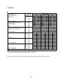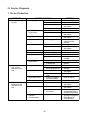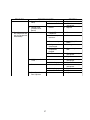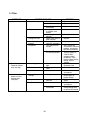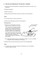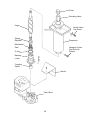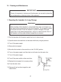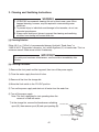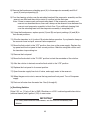
1
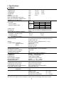
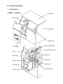
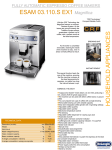
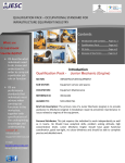
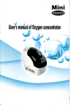
Hoshizaki
Hoshizaki America, Inc.
Self-Contained Flaker
Model
F-500BAF
“A Superior Degree
of Reliability”
SERVICE MANUAL
www.hoshizaki.com
Number: 73074
Issued: 3-2-1999
Revised: 12-26-2003
IMPORTANT
Only qualified service technicians should attempt to service or maintain this
icemaker. No service or maintenance should be undertaken until the technician
has thoroughly read this Service Manual.
HOSHIZAKI provides this manual primarily to assist qualified service technicians in the
service and maintenance of the icemaker.
Should the reader have any questions or concerns which have not been satisfactorily
addressed, please call or write to the HOSHIZAKI Technical Support Department for
assistance.
HOSHIZAKI AMERICA, INC.
618 Highway 74 South
Peachtree City, GA 30269
Attn: HOSHIZAKI Technical Support Department
Phone: 1-800-233-1940 Technical Service
(770) 487-2331
Fax:
(770) 487-3360
Web Site: www.hoshizakiamerica.com
Note: To expedite assistance, all correspondence/communication MUST include the
following information:
• Model Number
• Serial Number
• Complete and detailed explanation of the problem
2
Please review this manual. It should be read carefully before the icemaker is serviced or
maintenance operations are performed. Only qualified service technicians should service and
maintain the icemaker. This manual should be made available to the technician prior to service
or maintenance.
CONTENTS
I. Specifications .................................................................................................................... 5
F-500BAF ........................................................................................................................ 5
F-500BAF-C ..................................................................................................................... 6
II. General Information .......................................................................................................... 7
1. Construction ................................................................................................................. 7
F-500BAF, F-500BAF-C ............................................................................................. 7
2. Ice Making Unit ............................................................................................................. 8
3. Control Box Layout ....................................................................................................... 9
F-500BAF, F-500BAF-C ............................................................................................. 9
4. Timer Board ................................................................................................................ 10
[a] Solid-State Control .............................................................................................. 10
[b] Timer Board ......................................................................................................... 10
[c] Sequence ............................................................................................................ 11
III. Technical Information ..................................................................................................... 14
1. Water Circuit and Refrigerant Circuit........................................................................... 14
F-500BAF, F-500BAF-C ........................................................................................... 14
2. Wiring Diagram ........................................................................................................... 15
F-500BAF, F-500BAF-C ........................................................................................... 15
3. Sequence of Electrical Circuit .................................................................................... 16
F-500BAF, F-500BAF-C ......................................................................................... 16
4. Timing Chart ............................................................................................................... 21
5. Performance Data ....................................................................................................... 24
F-500BAF ................................................................................................................ 24
F-500BAF-C ............................................................................................................. 25
IV. Service Diagnosis .......................................................................................................... 26
1. No Ice Production ....................................................................................................... 26
2. Low Ice Production ..................................................................................................... 29
3. Other ........................................................................................................................... 30
V. Removal and Replacement of Components .................................................................. 31
1. Service for Refrigerant Lines ...................................................................................... 31
[a] Refrigerant Recovery........................................................................................... 31
[b] Evacuation and Recharge [R-404A] .................................................................... 31
2. Brazing ....................................................................................................................... 32
3. Removal and Replacement of Compressor ................................................................ 33
4. Removal and Replacement of Drier ........................................................................... 34
5. Removal and Replacement of Expansion Valve ......................................................... 35
6. Removal and Replacement of Evaporator Assembly ................................................ 36
7. Removal and Replacement of Fan Motor ................................................................... 40
8. Removal and Replacement of Control Water Valve .................................................... 40
3
VI. Cleaning and Maintenance .......................................................................................... 41
1. Preparing the Icemaker for Long Storage ................................................................... 41
2. Cleaning and Sanitizing Instructions .......................................................................... 42
[a] Cleaning Solution ................................................................................................ 42
[b] Cleaning Procedure ............................................................................................ 42
[c] Sanitizing Solution ............................................................................................... 43
[d] Sanitizing Procedure - Initial ................................................................................ 44
[e] Sanitizing Procedure - Final ................................................................................ 44
3. Maintenance Instructions ............................................................................................ 46
4
I. Specifications
F-500BAF
AC S UP P LY VOLTAGE
COMP RE S S OR
GE AR MOTOR
FAN MOTOR
OTHE R
MAXIMUM FUS E S IZE
MAX. HACR BREAKER (USA ONLY)
MAX. CIRC. BRE AKE R (CANADA ONLY)
MINIMUM CIRCUIT AMP ACITY
AP P ROXIMATE ICE P RODUCTION
P E R 24 HR.
lbs./day ( kg/day )
Reference without *marks
S HAP E OF ICE
ICE QUALITY
AP P ROXIMATE S TORAGE CAP ACITY
E LE CTRIC & W ATE R CONS UMP TION
E LE CTRIC W (kW H/100 lbs.)
P OTABLE W ATE R
gal./24HR (gal./100 lbs.)
E XTE RIOR DIME NS IONS (W xDxH)
E XTE RIOR FINIS H
W E IGHT
CONNE CTIONS - E LE CTRIC
- W ATE R S UP P LY
- DRAIN
ICE MAKING S YS TE M
HARVE S TING S YS TE M
ICE MAKING W ATE R CONTROL
COOLING W ATE R CONTROL
BIN CONTROL S YS TE M
COMP RE S S OR
CONDE NS E R
E VAP ORATOR
RE FRIGE RANT CONTROL
RE FRIGE RANT CHARGE
DE S IGN P RE S S URE
P .C. BOARD CIRCUIT P ROTE CTION
COMP RE S S OR P ROTE CTION
GE AR MOTOR P ROTE CTION
RE FRIGE RANT CIRCUIT P ROTE CTION
LOW W ATE R P ROTE CTION
ACCE S S ORIE S - S UP P LIE D
- RE QUIRE D
OP E RATING CONDITIONS
DRAW ING NO. (DIME NS IONS )
115/60/1
120 V
7.9 RLA
51 LRA
120 V
1.6 FLA
1/6 HP
120 V
0.85 FLA
1/15 HP
120 V
0.03 A
20 A
20 A
20 A
20 A
Ambient
W ATE R TE MP . (ーF)
Temp.(ーF)
50
70
90
70
* 478 (217) 458 (208)
438 (199)
80
419 (190) 400 (182)
383 (174)
90
366 (166) * 359 (163)
335 (152)
100
320 (145) 306 (139) * 287 (130)
Flake
Approx. 70% , Ice (90/70ーF, Conductivity 200 オs/cm)
250 lbs.
90/70ーF
70/50ーF
900 (6.0)
854 (4.3)
43 (12)
57 (12)
38" x 29" x 36" (965 x 735 x 915 mm)
P VC Coated Galvanized S teel; Galvanized S teel (Rear);
S tainless S teel (Top)
Net 210 lbs. ( 95 kg ), Shipping 245 lbs. ( 111 kg )
P ermanent Connection
Inlet 1/2" FP T
Drain P an 3/4" FP T
Bin Drain 3/4" FP T
Auger type
Direct Driven Auger ( 1/6 HP Gear Motor )
Float S witch
N/A
Mechanical Bin Control ( P roximity S w. )
Hermetic, Model RS 43C1E -CAA
Air-cooled, Fin and tube type
Copper Tube on Cylinder
Thermostatic E xpansion Valve
R-404A,
1 lb.
(470 g)
High 460 P S IG, Low 290 P S IG
High Voltage Cut-off Relay
Auto-reset Overload P rotector
Manual reset Circuit Breaker
Auto-reset High P ressure Control S witch
Float S witch and Timer
Ice S coop, S pare Fuse
Legs
VOLTAGE RANGE
104 - 127 V
AMBIE NT TE MP .
45 - 100ー F
W ATE R S UP P LY TE MP .
45 - 90ー F
W ATE R S UP P LY P RE S S URE
10 - 113 P S IG
339850---
We reserve the right to make changes in specifications and design without prior notice.
5
F-500BAF-C
AC S UP P LY VOLTAGE
COMP RE S S OR
GE AR MOTOR
FAN MOTOR
OTHE R
MAXIMUM FUS E S IZE
MAX. HACR BREAKER (USA ONLY)
MAX. CIRC. BRE AKE R (CANADA ONLY)
MINIMUM CIRCUIT AMP ACITY
AP P ROXIMATE ICE P RODUCTION
P E R 24 HR.
lbs./day ( kg/day )
Reference without *marks
S HAP E OF ICE
ICE QUALITY
AP P ROXIMATE S TORAGE CAP ACITY
E LE CTRIC & W ATE R CONS UMP TION
E LE CTRIC W (kW H/100 lbs.)
P OTABLE W ATE R
gal./24HR (gal./100 lbs.)
E XTE RIOR DIME NS IONS (W xDxH)
E XTE RIOR FINIS H
W E IGHT
CONNE CTIONS - E LE CTRIC
- W ATE R S UP P LY
- DRAIN
ICE MAKING S YS TE M
HARVE S TING S YS TE M
ICE MAKING W ATE R CONTROL
COOLING W ATE R CONTROL
BIN CONTROL S YS TE M
COMP RE S S OR
CONDE NS E R
E VAP ORATOR
RE FRIGE RANT CONTROL
RE FRIGE RANT CHARGE
DE S IGN P RE S S URE
P .C. BOARD CIRCUIT P ROTE CTION
COMP RE S S OR P ROTE CTION
GE AR MOTOR P ROTE CTION
RE FRIGE RANT CIRCUIT P ROTE CTION
LOW W ATE R P ROTE CTION
ACCE S S ORIE S - S UP P LIE D
- RE QUIRE D
OP E RATING CONDITIONS
DRAW ING NO. (DIME NS IONS )
115/60/1
120 V
7.9 RLA
51 LRA
120 V
1.6 FLA
1/6 HP
120 V
0.85 FLA
1/15 HP
120 V
0.03 A
20 A
20 A
20 A
20 A
Ambient
W ATE R TE MP . (ーF)
Temp.(ーF)
50
70
90
70
* 431 (196) 415 (188)
398 (181)
80
381 (173) 365 (166)
350 (159)
90
336 (152) * 333 (151)
308 (140)
100
295 (134) 283 (128) * 263 (119)
Cubelet
Approx. 80% , Ice (90/70ーF, Conductivity 200 オs/cm)
250 lbs.
90/70ーF
70/50ーF
903 (6.5)
864 (4.8)
40 (12)
52 (12)
38" x 29" x 36" (965 x 735 x 915 mm)
P VC Coated Galvanized S teel; Galvanized S teel (Rear);
S tainless S teel (Top)
Net 210 lbs. ( 95 kg ), Shipping 245 lbs. ( 111 kg )
P ermanent Connection
Inlet 1/2" FP T
Drain P an 3/4" FP T
Bin Drain 3/4" FP T
Auger type
Direct Driven Auger ( 1/6 HP Gear Motor )
Float S witch
N/A
Mechanical Bin Control ( P roximity S w. )
Hermetic, Model RS 43C1E -CAA
Air-cooled, Fin and tube type
Copper Tube on Cylinder
Thermostatic E xpansion Valve
R-404A,
1 lb.
(470 g)
High 460 P S IG, Low 290 P S IG
High Voltage Cut-off Relay
Auto-reset Overload P rotector
Manual reset Circuit Breaker
Auto-reset High P ressure Control S witch
Float S witch and Timer
Ice S coop, S pare Fuse
Legs
VOLTAGE RANGE
104 - 127 V
AMBIE NT TE MP .
45 - 100ー F
W ATE R S UP P LY TE MP .
45 - 90ー F
W ATE R S UP P LY P RE S S URE
10 - 113 P S IG
339850---
We reserve the right to make changes in specifications and design without prior notice.
6
II. General Information
1. Construction
F-500BAF, F-500BAF-C
Top Panel
Side Panel
Side Panel
Sliding Door
Water Supply Inlet
Front Panel
Control Water Valve
Spout
Reservoir
Gear Motor
Evaporator
Access Valve
Condenser
Compressor
Condenser Fan
Control Box
7
2. Ice Making Unit
8
3. Control Box Layout
F-500BAF, F-500BAF-C
PRESSURE
SWITCH
CONNECTOR
TRANSFORMER
CONTROL
TIMER
FLUSH VALVE
CONTROL RELAY
FLUSH
STARTER
FLUSH SWITCH
ICE
ON
POWER SWITCH
RUN
CAPACITOR
OFF
FUSE
CIRCUIT PROTECT
RELAY
CIRCUIT
BREAKER
START
CAPACITOR
GEAR MOTOR
PROTECT RELAY
CAPACITOR FOR
GEAR MOTOR
CAPACITOR FOR
FAN MOTOR
WATER CONTROL
RELAY
Note: The above component names are identical with the wiring label, but not with the parts list.
9
4. Timer Board
[a] Solid-State Control
1) A HOSHIZAKI exclusive solid-state control is employed in the self-contained flaker
icemakers.
2) A printed circuit board (hereafter called “timer board”) includes a stable and high quality
control system.
3) All models are pre-tested and factory adjusted.
[b] Timer Board
CAUTION
1. Fragile, handle very carefully.
2. A timer board contains CMOS (Complementary Metal-Oxide
Semiconductor) integrated circuits, which are susceptible to failure due to
static discharge. It is especially important to use an anti-static wrist strap
when handling or replacing the board.
3. Do not touch the electronic devices on the board or the back of the board to
prevent damage to the board.
4. Do not change wiring and connections. Especially, never misconnect
terminals.
5. Do not fix the electronic devices or parts on the board in the field. Always
replace the whole board assembly when it goes bad.
The icemaker is controlled by the timer board for the following purposes:
1) To prevent the gear motor and the compressor from starting or stopping simultaneously.
2) To reduce remaining ice in the refrigeration casing.
3) To protect the unit in case of low water and low water pressure.
4) To protect the unit in case the bin control causes chattering.
10
Compressor Relay
Gear Motor Relay
Fig. 1
[c] Sequence
Fig. 2
11
PART CODE
MODEL
RATING
T1
T2
T3
T4
T5
T6
437305-01
H2AA144C01
24 VAC 50/60Hz
60±15 sec.
90±22 sec.
150±45 sec.
1 sec. or less
6.7 sec. ± 70%
6.7 sec. ± 70%
Fig. 3
12
Functions of Terminals
1) Terminals 1, 2
Power supply AC 24V.
2) Terminals 3, 4
Control X1 (GM) and X2 (CM) Relays.
When closed, energize X1 (GM) in 1 sec. and X2 (CM) in 60 sec.
When opened, de-energize X1 (GM) in 150 sec. and X2 (CM) in 90 sec.
3) Terminals 5, 6
Control X1 (GM) and X2 (CM) Relays.
When opened, de-energize X1 (GM) and X2 (CM) immediately.
When closed again, energize X1 (GM) in 1 sec. and X2 (CM) in 60 sec.
4) Terminals 7, 8, 9
X1 (GM) contacts.
8 is a movable contact, 7 is a make contact, and 9 is a break contact.
5) Terminals 10, 11
Control X2 (CM) Relays.
When opened, de-energize X2 (CM) immediately.
When closed, energize X2 (CM) immediately.
Note: 1. X2 Relay is a single pole, normally open relay, and its terminals are mounted
on the relay itself.
2. The above operation times are median. See Fig. 3 for details.
13
III. Technical Information
1. Water Circuit and Refrigerant Circuit
F-500BAF, F-500BAF-C
CONTROL
WATER
VALVE
SPOUT
FLOAT
SWITCH
WATER
INLET
WATER LEVEL
EVAPORATOR
RESERVOIR
EXPANSION
VALVE
OVERFLOW
GEAR
MOTOR
FLUSH
WATER
VALVE
DRAIN PAN
DRAIN
OUTLET
DRAIN PAN
DRIER
CONDENSER
CONDENSER
FAN MOTOR
PRESSURE
SWITCH
ACCESS
VALVE
COMPRESSOR
WATER CIRCUIT
REFRIGERANT CIRCUIT
14
ACCESS
VALVE
2. Wiring Diagram
F-500BAF, F-500BAF-C
15
3. Sequence of Electrical Circuit
F-500BAF, F-500BAF-C
[a] When power switch is moved to "ON" position and flush switch to "ICE"
position, water starts to be supplied to reservoir.
115-120/60/1
L
N
KC1 KC4
8
7
KC3 KC6
BR
5
O
RUN CAP.
3
CONTROL
SWITCH
1
V
CIRCUIT
PROTECT
RELAY (X5)
MOT.
PROTECTOR
3
1 KA9
C
S
KA1
15MFD
STARTER
5
2
COMP.
KA3
DBU
1
START CAP.
270-324MFD
W
BK
R
R
O
GEAR MOTOR
PROTECT RELAY
(X4)
K
CIRCUIT
SWITCH
3
4
5
6
7
8
(Y)
(DBU)
CONDENSER FAN MOTOR
KB6
(BR) P
KA2
(BR)
(W)
DBU
CAP.
KA8 10MFD
(O)
BK
GY
PRESSURE
SWITCH
2
GEAR
MOTOR
THERMAL
PROTECTOR
KA5
6
A
1
LBU
KA7
V
CAP.
2.5MFD
KA4
(BK)
O
O
W
(O)
TRANS.
KB2
9
(BK)
1
FLUSH WATER
VALVE
LBU
LBU
4
6
5
BK V
P
BR
3
R
10
11
GY
O
CONTROL
WATER VALVE
1
2
3
KB1
FLUSH RELAY (X6) P
K
3
BR
W
BK
R
O
GY
P
DBU
V
Y
LBU
BU
1
4
K
3
D
R
2
4
CONTROL
TIMER
KD2
5
R
7
8
BK 24V
FUSE (1A)
R
WIRE COLOR CODE
4
D
FLUSH
SWITCH
P
BIN CONTROL SWITCH
LBU
3
5
7
2
4
6
8
BR
DBU
O
BK
WATER CONTROL RELAY
(X3)
O
(F-500BAF(-C))
16
KD1
KB4
K
(BU)
3
B
(O)
KB5
(BK)
FLOAT SWITCH
BROWN
WHITE
BLACK
RED
ORANGE
GRAY
PINK
DARK BLUE
VIOLET
YELLOW
LIGHT BLUE
BLUE
[b] When reservoir has been filled up, gear motor starts immediately.
115-120/60/1
L
N
KC1 KC4
8
7
KC3 KC6
W
BR
5
CONTROL
SWITCH
1
CIRCUIT
PROTECT
RELAY (X5)
O
RUN CAP.
3
V
MOT.
PROTECTOR
3
1 KA9
C
S
KA1
15MFD
STARTER
5
2
COMP.
KA3
DBU
1
START CAP.
270-324MFD
BK
R
R
O
GEAR MOTOR
PROTECT RELAY
(X4)
KA6
CIRCUIT
SWITCH
3
4
5
6
7
8
(Y)
(DBU)
CONDENSER FAN MOTOR
KB6
(BR) P
KA2
(BR)
(W)
DBU
LBU
CAP.
10MFD
KA8
(O)
BK
GY
PRESSURE
SWITCH
2
GEAR
MOTOR
THERMAL
PROTECTOR
KA5
1
KA7
V
CAP.
2.5MFD
KA4
(BK)
O
O
W
(O)
TRANS.
9
(BK)
BK 24V
KB2
1
FLUSH WATER
VALVE
LBU
LBU
3
4
P
BK V
BR
3
6
5
BR
W
BK
R
O
GY
P
DBU
V
Y
LBU
BU
R
10
11
GY
O
CONTROL
WATER VALVE
1
1
4
2
3
KB1
FLUSH RELAY (X6) P
KD3
R
2
4
CONTROL
TIMER
KD2
5
R
7
8
FUSE (1A)
R
WIRE COLOR CODE
KD4
FLUSH
SWITCH
P
BIN CONTROL SWITCH
LBU
3
2
4
5
6
7
8
BR
DBU
O
BK
WATER CONTROL RELAY
(X3)
O
(F-500BAF(-C))
17
KD1
KB4
K
(BU)
3
B
(O)
KB5
(BK)
FLOAT SWITCH
BROWN
WHITE
BLACK
RED
ORANGE
GRAY
PINK
DARK BLUE
VIOLET
YELLOW
LIGHT BLUE
BLUE
[c] Compressor starts about 60 sec. after gear motor starts.
115-120/60/1
L
N
KC1 KC4
8
7
KC3 KC6
W
BR
5
CONTROL
SWITCH
1
CIRCUIT
PROTECT
RELAY (X5)
O
RUN CAP.
3
V
MOT.
PROTECTOR
3
1 KA9
C
S
KA1
15MFD
STARTER
5
2
COMP.
KA3
DBU
1
START CAP.
270-324MFD
BK
R
R
O
GEAR MOTOR
PROTECT RELAY
(X4)
KA6
CIRCUIT
SWITCH
3
4
5
6
7
8
(Y)
K
(BR)
(W)
DBU
LBU
V
CAP.
2.5MFD
6
B
(BR) P
KA2
KA7
(DBU)
CONDENSER FAN MOTOR
CAP.
10MFD
KA8
(O)
BK
GY
PRESSURE
SWITCH
2
GEAR
MOTOR
THERMAL
PROTECTOR
KA5
1
KA4
(BK)
O
O
W
(O)
TRANS.
KB2
9
(BK)
1
FLUSH WATER
VALVE
LBU
LBU
3
4
BK V
BR
3
6
5
R
10
P
BR
W
BK
R
O
GY
P
DBU
V
Y
LBU
BU
11
GY
O
CONTROL
WATER VALVE
1
1
4
2
3
KB1
FLUSH RELAY (X6) P
KD3
R
2
4
CONTROL
TIMER
KD2
5
R
7
8
BK 24V
FUSE (1A)
R
WIRE COLOR CODE
KD4
FLUSH
SWITCH
P
BIN CONTROL SWITCH
LBU
3
2
4
5
6
7
8
BR
DBU
O
BK
WATER CONTROL RELAY
(X3)
O
(F-500BAF(-C))
18
KD1
KB4
K
(BU)
3
B
(O)
KB5
(BK)
FLOAT SWITCH
BROWN
WHITE
BLACK
RED
ORANGE
GRAY
PINK
DARK BLUE
VIOLET
YELLOW
LIGHT BLUE
BLUE
[d] Compressor stops about 90 sec. after bin control operates. Gear motor stops about
60 sec. later, and water is drained from the water circuit. Water can be also drained by
moving flush switch to "FLUSH" position.
115-120/60/1
L
N
KC1 KC4
8
7
KC3 KC6
W
BR
5
CONTROL
SWITCH
1
CIRCUIT
PROTECT
RELAY (X5)
O
RUN CAP.
3
V
MOT.
PROTECTOR
3
1 KA9
C
S
KA1
15MFD
STARTER
5
2
COMP.
KA3
DBU
1
START CAP.
270-324MFD
BK
R
R
O
GEAR MOTOR
PROTECT RELAY
(X4)
KA6
CIRCUIT
SWITCH
3
4
5
6
7
8
(Y)
K
(BR)
(W)
DBU
LBU
V
CAP.
2.5MFD
6
B
(BR) P
KA2
KA7
(DBU)
CONDENSER FAN MOTOR
CAP.
10MFD
KA8
(O)
BK
GY
PRESSURE
SWITCH
2
GEAR
MOTOR
THERMAL
PROTECTOR
KA5
1
KA4
(BK)
O
O
W
(O)
TRANS.
KB2
7
8
9
(BK)
BK 24V
FUSE (1A)
R
WIRE COLOR CODE
1
FLUSH WATER
VALVE
LBU
LBU
R
2
3
4
BK V
2
11
GY
O
CONTROL
WATER VALVE
3
KB1
FLUSH RELAY (X6) P
KD4
FLUSH
SWITCH
P
BIN CONTROL SWITCH
O
P
1
3
KD3
R
10
1
4
R
BR
3
6
5
KD2
5
4
CONTROL
TIMER
BR
W
BK
R
O
GY
P
DBU
V
Y
LBU
BU
LBU
2
4
5
6
7
8
BR
DBU
O
BK
WATER CONTROL RELAY
(X3)
(F-500BAF(-C))
19
KD1
KB4
K
(BU)
3
B
(O)
KB5
(BK)
FLOAT SWITCH
BROWN
WHITE
BLACK
RED
ORANGE
GRAY
PINK
DARK BLUE
VIOLET
YELLOW
LIGHT BLUE
BLUE
[e] When 208 - 230V are supplied to the power supply due to miswiring, circuit protect
relay operates, and the icemaker does not run.
115-120/60/1
L
N
KC1 KC4
8
7
KC3 KC6
W
BR
5
CONTROL
SWITCH
1
CIRCUIT
PROTECT
RELAY (X5)
O
RUN CAP.
3
K
15MFD
V
MOT.
PROTECTOR
3
1 KA9
C
S
1
A
STARTER
5
2
COMP.
KA3
DBU
1
START CAP.
270-324MFD
BK
R
R
O
GEAR MOTOR
PROTECT RELAY
(X4)
K
CIRCUIT
SWITCH
3
4
5
6
7
8
(Y)
(BR)
(W)
DBU
LBU
V
CAP.
2.5MFD
KB6
(BR) P
KA2
KA7
(DBU)
CONDENSER FAN MOTOR
CAP.
10MFD
KA8
(O)
BK
GY
PRESSURE
SWITCH
2
GEAR
MOTOR
THERMAL
PROTECTOR
KA5
6
A
1
KA4
(BK)
O
O
W
(O)
TRANS.
9
(BK)
BK 24V
KB2
1
FLUSH WATER
VALVE
LBU
LBU
3
4
BK V
BR
3
6
5
R
10
P
BR
W
BK
R
O
GY
P
DBU
V
Y
LBU
BU
11
GY
O
CONTROL
WATER VALVE
1
1
4
2
3
KB1
FLUSH RELAY (X6) P
KD3
R
2
4
CONTROL
TIMER
KD2
5
R
7
8
FUSE (1A)
R
WIRE COLOR CODE
KD4
FLUSH
SWITCH
P
BIN CONTROL SWITCH
LBU
3
5
7
2
4
6
8
BR
DBU
O
BK
WATER CONTROL RELAY
(X3)
O
(F-500BAF(-C))
20
KD1
KB4
K
(BU)
3
B
(O)
KB5
(BK)
FLOAT SWITCH
BROWN
WHITE
BLACK
RED
ORANGE
GRAY
PINK
DARK BLUE
VIOLET
YELLOW
LIGHT BLUE
BLUE
Miswiring. Circuit Protect Relay operates.
Proper wiring. The unit starts.
BIN CONTROL
4. Timing Chart
OFF
1. CIRCUIT PROTECT
RELAY
ON
ON
OFF
UPPER
2. WATER LEVEL
LOWER
BOTTOM
UPPER
3. FLOAT
SWITCH
LOWER
4. WATER CONTROL
RELAY
5. CONTROL WATER
VALVE
6. FLUSH RELAY
ON
OFF
ON
OFF
ON
OFF
ON
OFF
ON
OFF
FLUSH
7. FLUSH SWITCH
8. FLUSH WATER
VALVE
9. BIN CONTROL
ICE
ON
OFF
ON
OFF
1 sec
10. GEAR MOTOR
RELAY
11. GEAR MOTOR
12. FAN MOTOR
150 sec
ON
OFF
ON
OFF
ON
OFF
60 sec
13. COMPRESSOR
ON
OFF
14. PRESSURE
ON
SWITCH
OFF
21
90 sec
CONDENSER FAN FAILURE
LOW WATER
1. CIRCUIT PROTECT
RELAY
ON
OFF
UPPER
2. WATER LEVEL
LOWER
BOTTOM
UPPER
3. FLOAT
SWITCH
LOWER
4. WATER CONTROL
RELAY
5. CONTROL WATER
VALVE
ON
OFF
ON
OFF
ON
OFF
ON
OFF
ON
6. FLUSH RELAY
OFF
FLUSH
7. FLUSH SWITCH
8. FLUSH WATER
VALVE
9. BIN CONTROL
ICE
ON
OFF
ON
OFF
150 sec
10. GEAR MOTOR
RELAY
11. GEAR MOTOR
12. FAN MOTOR
1 sec
ON
OFF
ON
OFF
ON
OFF
90 sec
13. COMPRESSOR
60 sec
ON
OFF
14. PRESSURE
ON
SWITCH
OFF
22
FLUSH SWITCH
FLUSH
1. CIRCUIT PROTECT
RELAY
ICE
ON
OFF
UPPER
2. WATER LEVEL
UPPER
3. FLOAT
SWITCH
LOWER
4. WATER CONTROL
RELAY
5. CONTROL WATER
VALVE
LOWER
BOTTOM
ON
OFF
ON
OFF
ON
OFF
ON
OFF
ON
6. FLUSH RELAY
7. FLUSH SWITCH
8. FLUSH WATER
VALVE
9. BIN CONTROL
OFF
FLUSH
ICE
ON
OFF
ON
OFF
150 sec
10. GEAR MOTOR
RELAY
11. GEAR MOTOR
1 sec
ON
OFF
ON
OFF
60 sec
12. FAN MOTOR
ON
OFF
90 sec
13. COMPRESSOR
ON
OFF
14. PRESSURE
ON
SWITCH
OFF
23
5. Performance Data
F-500BAF
APPROXIMATE
ICE PRODUCTION
PER 24 HR.
lbs./day (kg/day)
APPROXIMATE ELECTRIC
CONSUMPTION
watts
APPROXIMATE WATER
CONSUMPTION PER 24 HR.
gal./day (l/day)
EVAPORATOR OUTLET TEMP.
°F (°C)
HEAD PRESSURE
PSIG (kg/cm²G)
SUCTION PRESSURE
PSIG ( kg/cm²G )
TOTAL HEAT OF REJECTION
Ambient
Temp. (°F)
70
80
90
100
70
80
90
100
70
80
90
100
70
80
90
100
70
80
90
100
70
80
90
100
Water Temp.
50
70
*478 *(217)
458
(208)
419
(190)
400
(182)
366
(166)
*359 *(163)
320
(145)
306
(139)
*854
-861
-874
-880
-893
-*900
-915
-923
-*57
*(217)
55
(208)
50
(190)
48
(182)
44
(166)
*43
*(163)
38
(145)
37
(139)
*8
*(-13)
8
(-13)
8
(-13)
12
(-11)
12
(-11)
*11
*(-11)
15
(-9)
15
(-9)
*221 *(15.5) 221
(15.6)
253
(17.8)
253
(17.8)
285
(20)
*285
*(20)
327
(23)
327
(23)
*26
*(1.8)
26
(1.8)
28
(2.0)
28
(2.0)
31
(2.1)
*31
*(2.0)
34
(2.4)
34
(2.4)
4683 BTU/h (AT 90°F /WT 70°F)
(°F)
90
438
383
335
*287
867
887
908
*930
53
46
40
*34
8
12
15
*15
221
253
285
*327
26
28
31
*34
Note: The data without *marks should be used for reference.
We reserve the right to make changes in specifications and design without prior notice.
24
(199)
(174)
(152)
*(130)
----(199)
(174)
(152)
*(129)
(-13)
(-11)
(-9)
*(-9)
(15.5)
(17.8)
(20)
*(23)
(1.8)
(2.0)
(2.1)
*(2.4)
F-500BAF-C
APPROXIMATE
ICE PRODUCTION
PER 24 HR.
lbs./day (kg/day)
APPROXIMATE ELECTRIC
CONSUMPTION
watts
APPROXIMATE WATER
CONSUMPTION PER 24 HR.
gal./day (l/day)
EVAPORATOR OUTLET TEMP.
°F (°C)
HEAD PRESSURE
PSIG (kg/cm²G)
SUCTION PRESSURE
PSIG ( kg/cm²G )
TOTAL HEAT OF REJECTION
Ambient
Temp. (°F)
70
80
90
100
70
80
90
100
70
80
90
100
70
80
90
100
70
80
90
100
70
80
90
100
Water Temp.
50
70
*431 *(196)
415
(188)
381
(173)
365
(166)
336
(152)
*333 *(151)
295
(134)
283
(128)
*864
-869
-880
-886
-897
-*902
-912
-917
-*52
*(196)
50
(188)
46
(173)
44
(166)
40
(152)
*40
*(151)
35
(134)
34
(128)
*9
*(-13)
9
(-13)
9
(-13)
12
(-11)
12
(-11)
*12
*(-11)
15
(-9)
15
(-9)
*225 *(15.8) 225
(15.8)
258
(18.1)
258
(18.1)
292
(20.5) *292 *(20.5)
332
(23.3)
332
(23.3)
*27
*(1.9)
27
(1.9)
30
(2.1)
30
(2.1)
32
(2.3)
*32
*(2.3)
35
(2.5)
35
(2.5)
4724 BTU/h (AT 90°F /WT 70°F)
(°F)
90
398
350
308
*263
875
891
907
*922
48
42
37
*32
9
12
15
*15
225
258
292
*332
27
30
32
*35
Note: The data without *marks should be used for reference.
We reserve the right to make changes in specifications and design without prior notice.
25
(181)
(159)
(140)
*(119)
----(181)
(159)
(140)
*(119)
(-13)
(-11)
(-9)
*(-9)
(15.8)
(18.1)
(20.5)
*(23.3)
(1.9)
(2.1)
(2.3)
*(2.5)
IV. Service Diagnosis
1. No Ice Production
PROBLEM
[1] The icemaker will
not start.
[2] Water does not
stop, and the
icemaker will not
start
POSSIBLE CAUSE
a) Power Supply
1.
2.
3.
b) Power Switch
(Control Box)
4. Blown fuse.
1. Off position.
2. Bad contacts.
4.
1.
2.
c) Fuse (Control Box)
1. Blown out.
1.
d) Circuit Protect Relay
1. Miswiring.
1.
e) Flush Switch
1. FLUSH position.
2. Bad contacts.
1.
2.
f) Transformer
g) Control Water Valve
h) Shut-off Valve
1.
1.
1.
2.
Coil winding opened.
Coil winding opened.
Closed.
Water failure.
1.
1.
1.
2.
i)
1. Disconnected.
2. Terminal out of Plug
or Receptacle.
1. Contact fused.
2. Coil winding opened.
1. Bad contacts.
1.
2.
2.
1.
Clean or replace
d) Hoses
a) Water Control Relay
2. Float does not move
freely.
1. Valve seat clogged
and water leaking.
1. Disconnected.
1. Bad contacts.
Move to ON position.
Tighten.
Check for continuity
and replace.
Replace.
Move to ON position.
Check for continuity
and replace.
Check for short circuit
and replace.
Check power supply
voltage and wire
properly.
Move to ICE position.
Check for continuity
and replace.
Replace.
Replace.
Open.
Wait till water is
supplied.
Connect.
Insert terminal back in
position
Replace.
Replace.
Check for continuity
and replace.
Clean or replace.
1.
b) Bin Control
1. Bad contacts.
Connect.
Check for continuity
and replace.
Check for continuity
and replace.
Clean axle and its
corresponding holes
or replace Bin Control.
Find out the cause,
get rid of it, and press
Reset Button on
Circuit Breaker.
Plug and Receptacle
(Control Box)
a) Water Control Relay
b) Float Switch
c) Flush Water Valve
[3] Water has been
supplied, but the
icemaker will not
start.
REMEDY
1. OFF position.
2. Loose connection.
3. Bad contacts.
1.
2.
1.
2. Activator does not
move freely.
c) Gear Motor
Protector
(Circuit Breaker)
1. Tripped.
26
1.
PROBLEM
POSSIBLE CAUSE
d) Gear Motor Protect
Relay
[4] Gear Motor starts,
but Compressor will
not start or operates
intermittently
REMEDY
1. Coil winding opened. 1. Replace.
2. Bad contacts.
2. Check for continuity
and replace.
1. Broken.
1. Replace.
e) Control Timer
(Printed Circuit
Board)
a) Pressure Switch
1. Dirty Air Filter or
1. Clean.
Condenser.
2. Ambient temperature 2. Get cooler.
too warm.
3. Fan not rotating.
4. Refrigerant
overcharged.
5. Refrigerant line or
components
plugged.
6. Bad contacts.
b) X2 Relay on Control
Timer
7.
1.
2.
1.
c) Starter
2.
3.
1.
d) Start Capacitor or
Run Capacitor
27
3. See "3. [1] a) Fan
Motor."
4. Recharge.
5. Clean and replace
drier.
6. Check for continuity
and replace.
Loose connections. 7. Tighten.
Bad contacts.
1. Check for continuity
and replace.
Coil winding opened. 2. Replace Timer.
Bad contacts.
1. Check for continuity
and replace.
Coil winding opened. 2. Replace.
Loose Connections. 3. Tighten.
Defective.
1. Replace.
PROBLEM
POSSIBLE CAUSE
e) Compressor
3. Motor Protector
tripped.
f)
[5] Gear Motor and
Compressor start
but no ice is
produced.
Power Supply
a) Refrigerant Line
REMEDY
1. Loose connections. 1. Tighten.
2. Motor winding
2. Replace.
opened or grounded.
1. Circuit Ampacity too
low.
1. Gas leaks.
2. Refrigerant line
clogged.
28
3. Find out the cause of
overheat or
overcurrent.
1. Install a larger-sized
conductor.
1. Check for leaks with a
leak detector. Reweld
leak, replace drier and
charge with
refrigerant. The
amount of refrigerant
is marked on
Nameplate or Label.
2. Replace the clogged
component.
2. Low Ice Production
PROBLEM
[1] Low ice production
POSSIBLE CAUSE
a) Refrigerant Line
1. Gas leaks.
REMEDY
1. See "1. [5] a)
Refrigerant Line."
2. Replace the clogged
component.
3. Recharge.
1. Clean.
2. Refrigerant line
clogged.
3. Overcharged.
1. Dirty Air Filter or
Condenser.
2. Ambient temperature 2. Get cooler.
too warm.
b) High-side Pressure
Too High
3. Fan rotating too
slow.
1. Low-side pressure
too low.
2. Low-side pressure
too high.
c) Expansion Valve
(not adjustable)
29
3. See "3 [1] a) Fan
Motor."
1. Replace.
2. See if Expansion
Valve Bulb is mounted
properly, and replace
the valve if necessary.
3. Other
PROBLEM
[1] Abnormal noise
POSSIBLE CAUSE
a) Fan Motor
b) Compressor
c) Refrigerant Lines
d) Gear Motor (Ice
Making)
e) Evaporator
1. Bearing worn out.
2. Fan blade deformed.
3. Fan blade does not
move freely.
1. Bearings worn out,
or cylinder valve
broken.
2. Mounting pad out of
position.
1. Rub or touch lines or
other surfaces.
1. Bearing or Gear
worn out / damaged.
1. Low-side pressure
too low.
2.
[2] Overflow from
Reservoir (Water
does not stop.)
[3] Gear Motor Fuse
blows or Circuit
Breaker trips
frequently.
a) Water Supply
1.
b) Control Water Valve
1.
c) Float Switch
1.
a) Power Supply
Voltage
1.
b) Evaporator Assy
1.
c) Bin Control
1.
2.
30
REMEDY
1. Replace.
2. Replace fan blade.
3. Replace.
1. Replace.
2. Reinstall.
1. Replace.
1. Replace.
1. See if Expansion
Valve Bulb is mounted
properly, and replace
the valve if necessary.
Scale on inside wall 2. Remove Auger. Use
of Freezing Cylinder.
"SCALE AWAY" or
"LIME-A-WAY"
solution to clean
periodically. If the
water is found hard by
testing, install a
softener.
Water pressure too
1. Install a pressure
high.
Reducing Valve
Diaphragm does not 1. Clean or replace.
close.
Bad contacts.
1. Check for continuity
and replace.
Too high or too low. 1. Connect the unit to a
power supply of
proper voltage.
Bearings or Auger
1. Replace Bearing or
worn out.
Auger.
Bad contacts.
1. Check for continuity
and replace.
Activator does not
2. Clean Axle and its
move freely.
corresponding holes
or replace Bin Control.
V. Removal and Replacement of Components
IMPORTANT
Ensure all components, fasteners and thumbscrews are securely in place
after the equipment is serviced.
IMPORTANT
1. The Polyol Ester (POE) oils used in R-404A units can absorb moisture
quickly. Therefore it is important to prevent moisture from entering the
system when replacing or servicing parts.
2. Always install a new filter drier every time the sealed refrigeration system
is opened.
3. Do not leave the system open for longer than 15 minutes when replacing
or servicing parts.
1. Service for Refrigerant Lines
[a] Refrigerant Recovery
The icemaker unit is provided with two refrigerant access valves - one on the low-side and
one on the high-side line. Using proper refrigerant practices recover the refrigerant from the
access valves and store it in an approved container. Do not discharge the refrigerant into
the atmosphere.
[b] Evacuation and Recharge [R-404A]
1) Attach charging hoses, a service manifold and a vacuum pump to the system. Be sure
to connect charging hoses to both high-side and low-side access valves.
IMPORTANT
The vacuum level and vacuum pump may be the same as those for current
refrigerants. However, the rubber hose and gauge manifold to be used for
evacuation and refrigerant charge should be exclusively for POE oils.
2) Turn on the vacuum pump. Never allow the oil in the vacuum pump to flow backward.
3) Allow the vacuum pump to pull down to a 29.9" Hg vacuum. Evacuating period
depends on pump capacity.
4) Close the low-side valve and high-side valve on the service manifold.
31
5) Disconnect the vacuum pump, and attach a refrigerant service cylinder to the highside line. Remember to loosen the connection, and purge the air from the hose. See
the nameplate for the required refrigerant charge. Hoshizaki recommends only virgin
refrigerant or reclaimed refrigerant which meets ARI Standard No. 700-88 be used.
6) A liquid charge is recommended for charging an R-404A system. Invert the service
cylinder. Open the high-side, service manifold valve.
7) Allow the system to charge with liquid until the pressures balance.
8) If necessary, add any remaining charge to the system through the low-side. Use a
throttling valve or liquid dispensing device to add the remaining liquid charge
through the low-side access port with the unit running.
9) Close the two refrigerant access valves, and disconnect the hoses and service
manifold.
10) Cap the access valves to prevent a possible leak.
2. Brazing
WARNING
1. Refrigerant R-404A itself is not flammable at atmospheric pressure and
temperatures up to 176°F.
2. Refrigerant R-404A itself is not explosive or poisonous. However, when
exposed to high temperatures (open flames) R-404A can be
decomposed to form hydrofluoric acid and carbonyl fluoride both of
which are hazardous.
3. Always recover the refrigerant and store it in an approved container. Do
not discharge the refrigerant into the atmosphere.
4. Do not use silver alloy or copper alloy containing arsenic.
5. Do not use R-404A as a mixture with pressurized air for leak testing.
Refrigerant leaks can be detected by charging the unit with a little
refrigerant, raising the pressure with nitrogen and using an electronic
leak detector.
Note: All brazing-connections are clear-paint coated. Sandpaper the brazingconnections before unbrazing the components. Use a good abrasive cloth to
remove coating.
32
3. Removal and Replacement of Compressor
IMPORTANT
Always install a new drier every time the sealed refrigeration system is
opened. Do not replace the drier until after all other repair or replacement
has been made.
1) Unplug the icemaker.
2) Remove the panels.
2) Remove the terminal cover on the compressor, and disconnect the compressor
wiring.
3) Recover the refrigerant and store it in an approved container, if required by an
applicable law.
4) Remove the discharge, suction, and access pipes from the compressor using
brazing equipment.
WARNING
When repairing a refrigerant system, be careful not to let the burner flame
contact any electrical wires or insulation.
5) Remove the bolts and rubber grommets.
6) Slide and remove the compressor. Unpack the new compressor package. Install
the new compressor.
7) Attach the rubber grommets of the prior compressor.
8) Sandpaper the discharge, suction and access pipes.
9) Place the compressor in position, and secure it using the bolts.
10) Remove plugs from the discharge, suction and access pipes.
11) Braze the access, suction and discharge lines (Do not change this order),
while purging with nitrogen gas flowing at the pressure of 3-4 PSIG.
12) Install the new drier.
33
13) Check for leaks using nitrogen gas (140 PSIG) and soap bubbles.
14) Evacuate the system, and charge it with refrigerant. See the nameplate for the
required refrigerant charge and type.
15) Connect the terminals to the compressor, and replace the terminal cover in its
correct position.
16) Replace the panels in their correct position.
17) Plug in the icemaker.
4. Removal and Replacement of Drier
IMPORTANT
Always install a new drier every time the sealed refrigeration system is
opened. Do not replace the drier until after all other repair or replacement
has been made.
1) Unplug the icemaker.
2) Remove the panels.
3) Recover the refrigerant and store it in an approved container, if required by an
applicable law.
4) Remove the drier using brazing equipment.
5) Install the new drier with the arrow on the drier in the direction of the refrigerant flow.
Use nitrogen gas at the pressure of 3-4 PSIG when brazing the tubings.
6) Check for leaks using nitrogen gas (140 PSIG) and soap bubbles.
7) Evacuate the system, and charge it with refrigerant. See the nameplate for the
required refrigerant charge and type.
8) Replace the panels in their correct position.
9) Plug in the icemaker.
34
5. Removal and Replacement of Expansion Valve
IMPORTANT
Sometimes moisture in the refrigerant circuit exceeds the drier capacity
and freezes up at the expansion valve. Always install a new drier every
time the sealed refrigeration system is opened. Do not replace the drier
until after all other repairs or replacement have been made.
1) Unplug the icemaker.
2) Remove the panels.
3) Recover the refrigerant and store it in an approved container, if required by an
applicable law.
4) Remove the expansion valve bulb at the evaporator outlet.
5) Remove the expansion valve cover, and remove the expansion valve using
brazing equipment.
6) Braze the new expansion valve with nitrogen gas flowing at the pressure of 3-4
PSIG.
WARNING
Always protect the valve body by using a damp cloth to prevent the valve
from overheating. Do not braze with the valve body exceeding 250°F.
7) Install the new drier.
8) Check for leaks using nitrogen gas (140 PSIG) and soap bubbles.
9) Evacuate the system. Charge it with refrigerant. See the nameplate for the required
refrigerant charge and type.
10) Attach the bulb to the suction line. Be sure to secure the bulb using a band and
to insulate it.
11) Place the expansion valve cover in position.
12) Replace the panels in their correct position.
13) Plug in the icemaker.
35
6. Removal and Replacement of Evaporator Assembly
1) Drain the water from the evaporator by switching the flush switch to “FLUSH” on the
control box.
2) Unplug the icemaker.
3) Remove the panels.
4) Remove the three thumbscrews and take off the spout from the evaporator.
Cutter
5) Loosen the cutter by a wrench and remove it.
6) Remove the cylinder gasket at the top of the evaporator.
Extruding Head
7) Grasp the top of the auger and move the
auger towards you and then try to insert a
.02" round stock or pin gauge in between
the back side of the auger shaft and the
bearing surface. Check several locations
around the auger shaft. If the gauge goes
between the shaft and the bearing at any
point, both the top bearing in the extruding
head and the lower bearing in the housing
should be replaced. Instructions for
removing the housing are located later in
this procedure.
.02” Round Stock
or Pin Gauge
Auger
Extruding
Head
Note: Replacing the bearing requires a bearing press adaptor. If one is not available,
replace the whole extruding head and housing.
8) Remove the three socket head cap screws and lift off the extruding head.
Auger
9) Lift out the auger. If the area in contact with the bearing is worn or the blade is
scratched, replace the auger.
36
Evaporator
Note: Skip the following steps 10) through 12) when the evaporator does not need
replacement.
10) Recover the refrigerant and store it in an approved container, if required by an
applicable law.
IMPORTANT
Always install a new drier every time the sealed refrigeration system is
opened. Do not replace the drier until after all other repair or replacement
has been made.
11) Remove the bulb of the expansion valve.
12) Disconnect the brazing-connections of the expansion valve and the copper tubelow side from the evaporator, using brazing equipment.
13) Remove the two truss head machine screws and the bracket securing the
evaporator.
14) Disconnect the three hoses from the evaporator.
15) Remove the four socket head cap screws securing the evaporator with the bearinglower.
16) Lift off the evaporator.
Housing, Lower Bearing and Mechanical Seal
17) The mechanical seal consists of two parts. One moves along with the auger, and the
other is fixed on the housing. If the contact surfaces of these two parts are worn or
scratched, the mechanical seal may cause water leaks and should be replaced.
18) Remove the O-ring from the housing.
19) Remove the four bolts and the housing from the gear motor. If inspection of the
bearing inside the extruding head (earlier in this procedure) indicated that it is out of
tolerance, replace both it and the bearing inside the housing.
Note: Replacing the bearing requires a bearing press adaptor. If one is not available,
replace the whole extruding head and housing.
37
Gear Motor
20) Remove the coupling-spline on the gear motor shaft.
21) Remove the three bolts securing the gear motor.
22) Assemble the removed parts in the reverse order of the above procedure.
WARNING
Be careful not to scratch the surface of the O-ring, or it may cause water leaks.
Handle the mechanical seal with care not to scratch nor to contaminate its
contact surface.
23) When replacing the evaporator:
(a) Braze the new evaporator with nitrogen gas flowing at the pressure of 3-4 PSIG.
(b) Replace the drier.
(c) Check for leaks using nitrogen gas (140 PSIG) and soap bubbles.
(d) Evacuate the system. Charge it with refrigerant. See the nameplate for required
refrigerant charge and type.
24) Replace the panels in their correct position.
25) Plug in the icemaker.
38
Cutter
Extruding Head
Auger
Socket Head
Cap Screw
Spring
Retainer
Evaporator
Mechanical
Seal
Hexagon Socket
Cap Bolt with
Washer
O-ring
BearingLower
CouplingSpline
Barrier
Gear Motor
39
7. Removal and Replacement of Fan Motor
1) Unplug the icemaker.
2) Remove the panels.
3) Remove the wire connectors from the fan motor leads.
4) Remove the fan motor bracket and fan motor.
5) Install the new fan motor.
6) Replace the fan motor bracket and the wire connectors.
7) Replace the panels in their correct position
8) Plug in the icemaker.
8. Removal and Replacement of Control Water Valve
1) Unplug the icemaker.
2) Remove the panels.
3) Close the water supply line shut-off valve.
4) Disconnect the terminal from the control water valve.
5) Loosen the fitting nut on the control water valve inlets, and remove the control water
valve. Do not lose the packings inside the fitting nut.
6) Remove the water supply hose from the control water valve.
7) Install the new control water valve.
8) Assemble the removed parts in the reverse order of the above procedure.
9) Open the water supply line shut-off valve.
10) Check for water leaks.
11) Replace the panels in their correct position.
12) Plug in the icemaker.
40
VI. Cleaning and Maintenance
IMPORTANT
Ensure all components, fasteners and thumbscrews are securely in place after
any maintenance or cleaning is done to the equipment.
1. Preparing the Icemaker for Long Storage
WARNING
When shutting off the icemaker for an extended time, drain out all water from
the water line and remove the ice from the storage bin. The storage bin should
be cleaned and dried. Drain the icemaker to prevent damage to the water
supply line at sub-freezing temperatures, using air or carbon dioxide. Shut off
the icemaker until the proper ambient temperature is resumed.
1) Run the icemaker with the water supply line shut-off valve closed.
2) Open the drain valve and blow out the water inlet line by using air pressure.
3) Turn off the power supply.
4) Remove the front panel.
5) Move the flush switch on the control box to the “FLUSH” position.
6) Turn on the power supply, and then drain out all water from the water line.
7) Turn off the power supply.
8) Turn off the power switch on the control box.
9) Replace the front panel in its correct position.
10) Close the drain valve.
11) Remove all ice from the storage bin, and
clean the bin.
41
2. Cleaning and Sanitizing Instructions
WARNING
1. HOSHIZAKI recommends cleaning this unit at least once a year. More
frequent cleaning, however, may be required in some existing water
conditions.
2. To prevent injury to individuals and damage to the icemaker, do not use
ammonia type cleaners.
3. Always wear liquid-proof gloves to prevent the cleaning and sanitizing
solutions from coming into contact with skin.
[a] Cleaning Solution
Dilute 4.8 fl. oz. (142 ml) of recommended cleaner Hoshizaki “Scale Away” or
“LIME-A-WAY” (Economics Laboratory, Inc.) with 0.8 gallons (3 l) of warm water. This is a
minimum amount. Make more solution if necessary.
IMPORTANT
For safety and maximum effectiveness, use the solution immediately after
dilution.
[b] Cleaning Procedure
1) Remove the front panel and the top panel, then turn off the power supply.
2) Close the water supply line shut-off valve.
3) Remove all ice from the storage bin.
4) Move the flush switch to the “FLUSH” position.
5) Turn on the power supply and drain out all water from the water line.
6) Turn off the power supply.
Note: This unit is designed to start operating when the
reservoir is filled with water.
7) In the storage bin, remove the thumbscrews attaching
spout (B), then remove spout (B) and spout packing (B).
Spout (B)
Thumbscrews
Spout Packing (B)
Fig. 4
42
8) Remove the thumbscrews attaching spout (A) to the evaporator assembly and lift off
spout (A) and spout packing (A).
9) Pour the cleaning solution over the extruding head until the evaporator assembly and the
reservoir are filled and the solution starts to overflow into the drain pan.
Note: If there is excess scale on the extruding head, fill the evaporator assembly and
reservoir as described above, then use a clamp on the reservoir hose between the
reservoir and evaporator assembly to block flow. Pour additional cleaning fluid
over the extruding head until the evaporator assembly is completely full.
10) Using the thumbscrews, replace spouts (A) and (B) and spout packings (A) and (B) in
their correct positions.
11) Allow the icemaker to sit for about 10 minutes before operation. If you placed a clamp on
the reservoir hose in step 9, remove it before operation.
12) Move the flush switch to the “ICE” position, then turn on the power supply. Replace the
top panel and the front panel in their correct positions. Make ice using the solution until
the icemaker stops making ice.
13) Remove the front panel.
14) Move the flush switch to the “FLUSH” position to drain the remainder of the solution.
15) After the solution is drained, move the flush switch to the “ICE” position.
16) Replace the front panel in its correct position.
17) Open the water supply line shut-off valve, and supply water to the reservoir.
18) When the gear motor starts, remove the top panel and front panel. Turn off the power
supply.
19) Drain out all water from the water line. See 4) through 6).
[c] Sanitizing Solution
Dilute 2.5 fl. oz. (74 ml or 5 tbs) of IMS-II Sanitizer or a 5.25% sodium hypochlorite solution
(chlorine bleach) with 5 gallons (19 l) of warm water.
IMPORTANT
For safety and maximum effectiveness, use the solution immediately after
dilution.
43
[d] Sanitizing Procedure - Initial
1) Close the water supply line shut-off valve.
2) In the storage bin, remove the thumbscrews attaching spout (B), then remove spout (B)
and spout packing (B).
3) Remove the thumbscrews attaching spout (A) to the evaporator assembly and
spout (A) and spout packing (A), and the cylinder packing.
lift off
4) Pour the sanitizing solution over the extruding head until the evaporator assembly and
the reservoir are filled and the solution starts to overflow into the drain pan.
5) Remove the thumbscrews attaching the bin control
assembly to the inside of the bin top panel.
Bracket
Thumbscrews
6) Remove the snap pin, shaft and actuator.
Snap Pin
7) Remove the sliding door.
Shaft
Actuator
8) Soak the removed parts in .25 gallons (1 l) of sanitizing
solution for 10 minutes then wipe them down.
Fig. 5
9) Rinse the parts thoroughly.
IMPORTANT
If the solution is left on these parts, they will rust.
10) Replace all parts in their correct positions.
11) Move the flush switch to the “ICE” position, then turn on the power supply. Replace the
top panel and the front panel in their correct positions. Make ice using the solution until
the icemaker stops making ice.
[e] Sanitizing Procedure - Final
1) Remove the front panel and the top panel, then turn off the power supply.
2) Move the flush switch to the “FLUSH” position.
3) Turn on the power supply and drain out all water from the water line.
4) Turn off the power supply.
Note: This unit is designed to start operating when the reservoir is filled with water.
5) In the storage bin, remove the thumbscrews attaching spout (B), then remove spout (B)
and spout packing (B).
44
6) Remove the thumbscrews attaching spout (A) to the evaporator assembly and lift off spout
(A) and spout packing (A).
7) Pour the sanitizing solution over the extruding head until the evaporator assembly and
the reservoir are filled and the solution starts to overflow into the drain pan.
8) Using the thumbscrews, replace spouts (A) and (B) and spout packings (A) and (B) in
their correct positions.
9) Allow the icemaker to sit for about 10 minutes before operation.
10) Move the flush switch to the “ICE” position, then turn on the power supply. Replace the
top panel and the front panel in their correct positions. Make ice using the solution until
the icemaker stops making ice.
11) Remove the front panel.
12) Move the flush switch to the “FLUSH” position to drain the remainder of the solution.
13) After the solution is drained, move the flush switch to the “ICE” position.
14) Replace the front panel in its correct position.
15) Open the water supply line shut-off valve and supply water to the reservoir.
16) When the gear motor starts, remove the front panel and turn off the power supply.
17) Drain out all water from the water line. See 2) and 3).
18) Move the flush switch to the “ICE” position and run the icemaker.
19) Turn off the power supply after 30 minutes.
20) Pour warm water into the storage bin to melt all ice, then clean the bin liner with the
solution.
21) Flush out any solution from the storage bin.
22) Turn on the power supply and start the automatic icemaking process.
IMPORTANT
1. After cleaning, do not use ice made from the sanitizing solution. Be careful
not to leave any solution in the storage bin.
2. Follow carefully any instructions provided with the bottles of cleaning or
sanitizing solution.
3. Never run the icemaker when the reservoir is empty.
45
3. Maintenance Instructions
IMPORTANT
1. This icemaker must be maintained individually, referring to the instruction
manual and labels provided with the icemaker.
2. To have the optimum performance of this icemaker, the following
consumable parts need periodic inspection, maintenance and
replacement:
Extruding Head
Housing
Gear Motor
Auger
Mechanical Seal
These parts should be inspected at least once a year or every 10,000 hours of
operation. Their service life, however, depends on water quality and
environment. More frequent inspection and maintenance are recommended.
Consult with your local distributor about inspection and maintenance service.
To obtain the name and phone number of your local distributor, call Hoshizaki
Technical Support at 1-800-233-1940 in the USA.
1) Stainless Steel Exterior
To prevent corrosion, wipe the exterior occasionally with a clean and soft cloth. Use a
damp cloth containing a neutral cleaner to wipe off oil or dirt build up.
2) Storage Bin and Scoop
• Wash your hands before removing ice. Use the plastic scoop provided (bin accessory).
• The storage bin is for ice use only. Do not store anything else in the bin.
• Keep the scoop clean. Clean using a neutral cleaner and rinse thoroughly.
• Clean the bin liner using a neutral cleaner. Rinse thoroughly after cleaning.
46
3) Air Filter
A plastic mesh air filter removes dirt or dust from the air, and keeps the condenser
from getting clogged. As the filter gets clogged, the icemaker’s performance will be
reduced. Check the filter at least twice a month. When clogged, use warm water and
a neutral cleaner to wash the filter.
4) Condenser
Check the condenser once a year, and clean if required by using a brush or vacuum
cleaner. More frequent cleaning may be required depending on the location of the
icemaker.
47