1
IDl TeleVldeo; Inc.
OPERATORS REFERENCE
HANDBOOK
TVI@·912B and TVI@·920B
TVI@·912C and TVI@·920C
©Copyright Televideo, Inc., 1979
1979 TeleVideo ®Inc.
. Specifications and information subject
to change without prior notification.
TABLE OF CONTENTS
1.0 General Features
1.1
0
•
•
•
••
Options............................................................... 1
2.0 General Description
2
3.0 Specifications
3.1
3.2
3.3
3.4
3.5
3.6
3.7
3.8
3.9
3.10
3.11
3.12
3.13
3.14
3.15
3.16
4.0
5.0
2
Monitor
Displayed Character Set. . . . . . . . . . . . . . . . . . . . . . . . . . . . . . . . . . . . . . . . . . . . . . . . . . . ..
Character Font
Keyboard Format
Editing Features. . . . . . . . . . . . . . . . . . . . . . . . . . . . . . . . . . . . . . . . . . . . . . . . . . . . . . . . ..
Cursor Controls . . . . . . . . . . . . . . . . . . . . . . . . . . . . . . . . . . . . . . . . . . . . . . . . . . . . . . . . ..
Formatting Features . . . . . . . . . . . . . . . . . . . . . . . . . . . . . . . . . . . . . . . . . . . . . . . . . . . . . ..
Parity.................................................................
Repeat................................................................
Transmission
Interfaces . . . . . . . . . . . . . . . . . . . . . . . . . . . . . . . . . . . . . . . . . . . . . . . . . . . . . . . . . . . . ..
Data Rates
Dimension. . . . . . . . . . . . . . . . . . . . . . . . . . . . . . . . . . . . . . . . . . . . . . . . . . . . . . . . . . . . ..
Weight
Operating Environment . . . . . . . . . . . . . . . . . . . . . . . . . . . . . . . . . . . . . . . . . . . . . . . . . . . ..
Power Requirements. . . . . . . . . . . . . . . . . . . . . . . . . . . . . . . . . . . . . . . . . . . . . . . . . . . . . ..
0
o'
•
•
•
•
•
•
• • • • • • • • • • • • • • • • • • • • • • • • • • • • • • • • • • • • • • • • • • • • • • •
•
•
•
•
•
•
•
•
•
•
•
•
•
•
•
•
•
•
•
•
•
•
•
•
•
•
•
•
•
•
•
•
•
•
••
0
• • • • • • • • • • • • •
•
•
•
•
•
•
•
•
•
•
•
0
•
•
•
•
•
•
•
•
••
2
2
2
2
2
2
3
3
3
3
3
3
3
3
3
3
Interconnection
4
4.1
4.2
4.3
4
4
4
Interconnections Steps
Main Interface Connector
Printer Interface
Installation................................................................ 5
5.1
5.2
5.3
6.0
1
Local Installation . . . . . . . . . . . . . . . . . . . . . . . . . . . . . . . . . . . . . . . . . . . . . . . . . . . . . . . .. 5
Remote Installation
5
Terminal TURN·ON Procedure
5
Functional Description of TVI·912/TVI-920
6.1
6.2
6.3
6.4
6.5
6.6
6.7
6.8
Keyboard..............................................................
Contrast Control
Transmission Rates. . . . . . . . . . . . . . . . . . . . . . . . . . . . . . . . . . . . . . . . . . . . . . . . . . . . . . ..
Mode Selection
6.4.1 Conversation Mode
6.4.2 Block Mode
Protect Mode. . . . . . . . . . . . . . . . . . . . . . . . . . . . . . . . . . . . . . . . . . . . . . . . . . . . . . . . . . ..
The Cursor
Editing Functions. . . . . . . . . . . . . . . . . . . . . . . . . . . . . . . . . . . . . . . . . . . . . . . . . . . . . . . ..
Formatting Capabilities
7.0 Operation of TVI-912/TVI·920
7.1
Of
7.2
7.3
7.4
7.5
7.6
7.7
7.8
7.9
Keyboard Functions
7.1.1 Control Keys - Functional Description.
Function Keys . . . . . . . . . . . . . . . . . . . . .
Numeric Key Pad . . . . . . . . . . . . . . . . . . .
ON/OFF Switch
TVI·912/TVI·920 Controls
Attribute Codes . . . . . . . . . . . . . . . . . . . .
Block Mode Message Transmission
Conversation Mode Transmission. . . . . . . . .
Self·Test Mode . . . . . . . . . . . . . . . . . . . . .
7.9.1 TVI·912/TVI·920 Test Pattern
6
6
6
6
6
6
6
6
7
7
7
7
. . . . . . . . . . . . . . . . . . . . . . . . . . . . . . . . . . . . ..
. . . . . . . . . . . . . . . . . . . . . . . . . . . . . . . . . . . ..
. . . . . . . . . . . . . . . . . . . . . . . . . . . . . . . . . . . ..
. . . . . . . . . . . . . . . . . . . . . . . . . . . . . . . . . . . ..
. . . . . . . . . . . . . . . . . . . . . . . . . . . . . . . . . . . ..
. . . . . . . . . . . . . . . . . . . . . . . . . . . . . . . . . . . ..
7
9
12
13
13
13
13
15
15
16
16
TABLE OF CONTENTS (cont't)
.•' Programming for Remote Computers . . . . . . . . . , . . . . . . . . . . . . . . . . , . . . . . . . . . . . . . . ..
8.1
8.2
8.3
CTRLFunctions
ESC Functions
Additional Remote Functions
,
,
17
, . . . . . . . . . . . . . . . . . . . . . .. 17
,
, . . . . .. 17
,
9.0 Word Structure
, . . . . ..
10.0 Serial Printer Interface . . . . . . . . . . . . . . . . . . . . . . . . . . . . . . . . . . . . . . . . . . . . . . . . . . . . . . . . . . . . . ..
10.1 Interface Connector
10.2 Transmission Rate
10.3 Print Modes
17
,
19
',' . . . ..
19
19
19
11.0 Second Page Memory Option . , . . . . . . . . . . . . . . . . . . . . . . . . . . . . . . . . . . . . . . . . . . . . . ..
21
11.1 Description
11.2 Alternate Page
11.3 Auto Flip
,
18
,
,
,
,
21
, . . . . . . . . . . . . . . . . . . . . . . . . . . . . . . . . . . . .. 21
,
21
'
12.0 Option Switch Selection
,
,
,
12.1 S2-UART Terminal Options
12.2 S5-UART Terminal Options
22
,
23
, .. , 23
Jumper Options
Half Duplex Active. . . . . . . . . . .
Half Duplex Passive
,
Full Duplex Passive. . . . . . . . . . .
Full Duplex Active XMTR
Control Board Switches
,
Addressable Cursor
,
Escape Sequences . . . . . . . . . . . .
TVI-912/TVI-920 ASCII Chart
Operators Quick Reference Control
. . . . . . . . . . . . . . . . . . . . . . . . . . . . . . . . . . . . . . . . . . ..
"
. . . . . . . . . . . . . . . . . . . . . . . . . . . . . . . . . . . . . . . . . . ..
, . . . . . . . . ..
, . . . . . . . . . . . . . . . ..
,
, . . . . . . . . . . . . . . . . . . . . . . . . . . . . . . . . ..
. . . . . . . . . . . . . . . . . . . . . . . . . . . . . . . . . . . . . . . . . . ..
,
"
. . . . . . . . . . . . . . . . . . . . . . . . . . . . . . . . . . . . . . . . . . ..
25
25
25
25
26
28
29
29
31
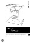
LIST OF PHOTOGRAPHS
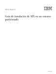
7.1 Keyboard Function. . . . . . . . . . . . . . . . . . . . . . . . . . . . . . . . . . . . . . . . . . . . . . . . . . . . . . ..
TVI.920@KeYboa~d
,
,
TVI·912@ Keyboard
7.9.1 TVI-912/TVI-920 Test Pattern. ,
12.0 Option Switch Selection
12.2 Operator Controls
"
Control Board Switches . . . . . . . . . . . . . . . . . . . . . . . . . . . . . . . . . . . . . . . . . . . . . . . . . . ..
Terminal Interior .... . . . . . . . . . . . . . . . . . . . . . . . . . . . . . . . . . . . . . . . . . . . . . . . . . . ..
8
B
8
16
22
24
26
27
LIST OF ILLUSTRATIONS
4.2
4.3
7.6
9.0
10.1
Main Interface Connector (EIA RS232C Connector Pin/Signal List)
Printer Interface. . . . . . . . . . . . . . . . . . . . . . . . . . . . . . . . . . . . . . . . . . . . . . . . . . . . . . . . ..
Example C: Bit Commands. . . . . . . . . . . . . . . . . . . . . . . . . . . . . . . . . . . . . . . . . . . . . . . . ..
Bit Structure of Serial Data Word
,.....................
Interface Connector-J3 Signal/Pin
4
4
15
18
19
Jumper Options
Half Duplex Active . . . . . . . . . . . . . . . . . . . . . . . .
Half Duplex Passive. . . . . . . . . . . . . . . . . . . . . . . .
Full Duplex Passive
Full Duplex Active XMTR
Addressable Cursor . . . . . . . . . . . . . . . . . . . . . . . .
Escape Sequences . . . . . . . . . . . . . . . . . . . . . . . . .
TVI·912/TVI·920 ASCII Chart. ,
Operators Quick Reference- TV'-912/TVI·920 Control
ii
. . . . . . . . . . . . . . . .. . . .. . . . . . .
. . . . . . . . . . . . . . . . . . . . . ..
,
,
. . . . . . . . . . . . . . . . . . . . . . . . . ..
. . . . . .. . . . . . . . . . . . . . . . . . . ..
:
. . ..
25
25
. . .. 25
. . .. 25
. . .. 28
. . .. 29
30
31
TVI-912/TVI-920 SERIES
VIDEO DISPLAY COMPUTER TERMINAL
OPERATOR'S MANUAL
1.0 GENERAL FEATURES
•
Standard 96 ASCII Character set displayable
•
1920 Character display
•
24 lines x 80 characters
•
9 transmission rates from 75 to 9600 bps
•
14-key numeric keypad
•
6 separate cursor control keys
•
Local or remote control of conversation/block mode
•
Single-key edit operations (TVI-920 only)
•
Page, field, or line edit
•
Blinking fields
•
Blank fields
•
Dual intensity
•
Reverse video
•
Underline fields
•
Field tab/back tab
•
Typewriter tabs
•
Storable tabs
•
Protect mode
•
Self-test mode
•
Cursor addressing & cursor read
•
15-cps repeat. Typamatic keyboard
•
Standard RS232, point-to-point 20ma current loop
•
Non-glare etched screen
•
115/230 VAC 50/60 Hz Refresh
•
Serial printer port
1.1 Options
•
Second page memory, 1920 characters
2.0 GENERAL DESCRIPTION
The TeleVideo TVI-912/TVI-920 terminals are compact smart terminals. They are the result of state-ofthe-art design improvements which allow them to offer high level performance at extremely low cost.
The TVI-912/TVI-920 terminals are compatible with most computers.
Standard features include editing capability, protected field, addressable cursor, micro-processor control, line and character insert/delete, upper and lower case characters and tabbing. Switchable transmission rates ranging from 75 to 9,600 baud are standard. Also included as standard is a buffered serial
printer port. A 1,920-character second page display memory is optional on all models.
3.0 SPECIFICATIONS
3.1
Monitor
Size:
12 inches (diagonally measured)
Phosphor: P4, non-glare read-out
3.2 Displayed Character Set
96-character ASCII upper and lower case alphabet
24
Number of lines:
Characters per line: 80
Screen capacity:
1,920
Dual intensity
Blinking fields
Secure fields (non-display)
Inverse video
Underlined fields
3.3 Character Font
7 x 10 dot matrix with 12 x 10 resolution
3.4 Key Board Format
3.5 Editing Features
Clear screen to space or null
Typeover
Character insert and character delete
Line insert and line delete
Absolute cursor addressing
Erase to end of page
Erase to end of line or field
Line edit
3.6 Cursor Controls
-+,~, t,,1,,
New line, Home, Tab, Back Tab
2
3.7
J
Formatting Features
Tab
Back tab
Column tab set
Blinking field
Inverse video
Underline
Dual intensity
Protected field
3.8 Parity
Even, Odd, Mark, Space or No Parity.
3.9 Repeat
15-cps auto-repeat
3.10 Transmission
Conversation mode: Full or half duplex
Block mode:
Formatted information transmitted by line or page, protected and unprotected, or unprotected only.
3.11 Interfaces
Standard RS232 point-to-point
20ma current loop
RS232 to printer port
3.12 Data Rates
9 speeds: 75, 110, 150,300,600, 1200,2400,4800,9600
3.13 Dimension
I
I
j
l
I
1
Height:
Width:
Depth:
13-1/4"
16-1/8"
20-1/16"
33.66 cm
40.96 em
50.96 em
3.14 Weight
301bs.
13.95 kg
3.15 Operating Environment
Ambient temperature range (non-condensing): OOC to 50°C (32°F to 122°F)
Maximum relative humidity: 95%.
3.16 Power Requirements
115/230 VAC, 50/60 Hz, 55W
3
4.0 INTERCONNECTION
4.1
Interconnection Steps
Step 1:
Making sure the power switch of the terminal is OF F, plug the terminal power cord
into grounded outlet.
Step 2:
Connect the cable from the remote computer or modem to the interface connector.
4.2 Main Interface Connector (EIA RS232C Connector Pin/Signal List)
Pin No.
Bell System Code
Signal Name
1
Frame Ground
AA
2
Transmit Data
SA
3
Receive Data
SS
4
Request to Send
CA
5
Clear to Send
CS
6
Data Set Ready (opt.)
7
Signal Ground
8
Carrier Detect
AS
20
Data Terminal Ready
25
Current Loop
13
Current Loop -
12
Current Loop
24
Cu rrent Loop -
CD
+
+
Transmit*
Receive
*Internal Strap Options for Active/Passive. (See page 25 "Jumper Options").
4.3 Printer Interface
Pin No.
Signal Name
1
3
4
Frame Ground
Serial Data (RS232)
Printer Ready (Jumper Select)
Terminal Ready (optional select)
Signal Ground
Data Carrier Detect
Printer Ready
6
7
8
20
4
5.0 INSTALLATION
5.1
Local Installation
The TVI-912/TVI-920 with a standard communications interface (RS232) can be cabled directly
to a local computer.
5.2
Remote Installation
The TVI-912/920 can communicate with remote computers using a modem connected between
the TVI-912/920 and the communication lines.
5.3 Terminal TURN-ON Procedure
Step 1.
First make sure that ON/OFF switch at the rear of the terminal is in OFF position.
Step 2.
Plug the terminal cord into a grounded 115VAC outlet.
Step 3.
Set the ON/OFF switch to ON position; the beep will sound.
Step 4.
Cursor will appear at its home position in approximately 20 seconds.
Step 5.
If the cursor does not appear at the "home" position, press HOME key. If the cursor
still does not appear, check if the brightness control is properly adjusted.
'l
J
!
J
i
5
6.0 FUNCTIONAL DESCRIPTIOI\I OF TVI-912/TVI·920
6.1
Keyboard
The TV 1-912 has a 84 key keyboard comprised of alphanumeric characters, symbols and control
keys to perform its full operation.
The TV 1-920B has a 103 key keyboard which adds 11 special function keys, six editing keys, and
two transmission keys.
The TV 1-912C has a 82 key keyboard, in a standard typewriter style, with alphanumeric characters,
symbols, and control keys.
The TV 1-920C has a 101 key keyboard, in a standard typewriter style, that adds 11 special function keys, six editing keys and two transmission keys.
6.2 Contrast Control
The brightness of displayed data on the screen can be adjusted by means of a control knob on the
rear of the TVI-912/TVI-920.
6.3 Transmission Rates
The TVI-912/TVI-920 meets the standard transmission rates of computer interfaces, telephone
data lines, and modems with 9 speeds: 75, 110,.150, 300, 600, 1200, 2400, 4800 or 9600 baud.
Speed is selected by means of switches on the rear of the terminal.
6.4 Mode Selection
The TVI-912B/TVI-920B selects Block Mode with CTRL/ESC. The TVI-912CITVI-920C selects
Conversation or Block Mode by operation of the Block Conversation key with "Control" or
"Shift."
6.4.1
Conversation Mode
Half Duplex: In Half Duplex mode, the TVI-912/TVI-920 sends and receives data in only
one direction at a time. Characters are displayed on the screen and transmitted to the
computer at the same time as they are typed from the keyboard. TV 1-912/TV 1-920
receives and displays data simu Itaneously.
Full Duplex: In Full Duplex, TVI-912/TVI-920 sends and receives data in both directions simultaneously. Characters are transmitted as they are typed, but they are not
displayed. The typed characters are echoed from the computer back to the terminal.
6.4.2
Block Mode
In Block Mode, TVI-912/TVI-920 sends and receives data in complete blocks. Data up
to a full screen can be entered by operator. In this mode, characters are stored and displayed but not transmitted until a special code sequence is received by the terminal, or
by the depression of a "send" key on the TVI-920. The edited data can be transmitted
partially or completely. This mode is utilized for fast transmission of large blocks of data.
6.5 Protect Mode
In Protect mode, those character positions designated as protected (lower intensity) cannot be
modified. The cursor cannot enter a protected field. The cursor will be advanced through the
protected field to the next unprotected position. The cursor may be back-spaced across a protected field.
6
I
I
I
6.6 The Cursor
The cursor of TVI-912/TVI-920 is a reverse video block, rectangular-shaped marker on the screen
which indicates the entry spot for the following character to be typed. When typing, the cursor
moves from left to right. If the cursor is placed over a character already displayed, the character
is changed into a reverse image inside the cursor. The cursor can be moved up, down, left, right
or home by pressing a cursor motion key. Any desired cursor position can be obtained using an
absolute cursor address of Y (line) and X (column) combination.
6.7
Editing Functions
Clear screen to spaces or nu lis
Character typeover
Clear unprotected positions
Character insert and character delete
Line insert.and line delete
Erase to end of line or field with spaces or nulls
Erase to end of page with spaces or nulls
6.8
Formatting Capabilities
Tabs:
When in protect mode, the tabs, forward and back, are set using columns of
protected characters. The TVI-912/TVI-920 also offers typewriter-style tab
when not in Protect mode. Up to 80 tab positions may be set without loss of
character location.
Field Reverse:
The data can be displayed as black characters on a white background.
Field Blinking:
Blinking fields can be designated over areas of the display and the designated
areas blink on and off, at a 2 Hertz rate.
Field Blanking:
Blank fields can be designated over areas of the display. The areas are blanked,
although the characters are still entered into display memory.
Field Protection: Protected fields can also be designated. The protected fields appear at a reduced instensity and, once designated as protected fields, cannot be over-written
unless the TVI-912/TVI-920 is removed from Protect mode.
7.0 OPERATION OF TVI-912/TVI-920
7.1
Keyboard Function
The TVI 912/TVI-920 keyboard contains alphanumeric keys to enter data, and function keys
(control keys) for controlling operation. For all the definitions of keyboards and control codes,
please refer to Quick Reference Guide (page 31).
Control Keys and Functional Description as follows:
7
TV I® -920B Keyboard
TVI®-920C Keyboard
TVI®-912B Keyboard
"
'oc
1
TAl
ALPHA
lO<:l
It
2
3
W
Q
UI
...C<
«i)
II
III
A
$
4
Z
&
6
7
C
Y
T
F
D
x
1\
5
R
E
S
%
B
(
)
9
0
0
U
H
G
V
*
8
N
M
=
.
<
mil
]
[
P
L
K
J
,,
+
>
\
liCK
'PACE
;Jill
II
F"ElO
7
8
9
4
5
6
1l1i1l1111 ..
?
I
2
II
0
A.~····
TVI®-912C Keyboard
8
3
7.1.1
Control Keys - Functional Description
Control Keys
TVI-912
TVI-920
CLEAR SP
(ALL)
Transmits a CTR LIZ, which when received by the terminal,
performs a clear unprotected to spaces.
CHAR INSERT
ESCQ
(920)
(ALL)
Moves character in the cursor position and all succeeding
characters to the right by one position. If no protected field
is encountered between the cursor and the end of the line,
th is operation term inates at the end of the Iine and the last
character in the line is lost. If a protected field is encountered,
and Protect Mode is on, the operation will terminate at the
end of the unprotected field at which the cursor rests, and
the last character in that field is lost.
CHAR DELETE
ESCW
(920)
(ALL)
Deletes character in cursor position. If no part of the line is
protected, characters following the cursor are moved to the
left. If the line has a protected field, only the characters from
the cursor to the protected field are moved to the left. This
operation terminates at the end of the line, if no protected
fields are on the line.
LINE INSERT
ESC E
(920)
(ALL)
Inserts a line of nulls between the line above the cursor and
the line where the cursor is positioned. At this time, the line
where the cursor was located and all following lines move one
line downwards. The cursor is positioned at the start of the
new line. The bottom line of the screen is lost. If in Protect
mode, no operation is performed.
LINE DELETE
ESC R
(920)
(ALL)
Deletes completely the line where the cursor is located. All
following lines move one line upwards. Cursor is positioned
at the start of the line. If in Protect mode, no operation is
performed.
LINE ERASE
ESC T, (ESC t)
(920)
(ALL)
Erases all character positions from cursor to the end of the
line where the cursor is located and replaces with Space
Codes (ESC T) or Null Codes (ESC t) if shifted (TV 1-920
only). If in protected mode, the operation will end at the
first protected location to the right of the cursor.
PAGE ERASE
ESC Y, (ESC y)
(920)
(ALL)
Erases all character positions from cursor through end of display and replaces with Space Codes (ESC V), or Null Codes
(ESC y) if shifted (TVI-920 only). If Write Protect is on, protected spaces or nulls will be written. (Note that if the entire
page is protected in Protect Mode, the cu rsor will stop in the
Home position and no further character may be entered until
an unprotected area is made available, or Protect Mode is
turned off.)
CTRL
(ALL)
Modifies the code transmitted by pressing another key.
f
j
Functional Description
I
I
9
ESC
(ALL)
RUBOUT
DEL
(912B,920B) This key is effective only in Conversation Mode. Computer
(912C,920C) normally interprets "RUBOUT" as a character erase code.
BREAK
(ALL)
Transmits the TTY break signal.
TAB
CTRUI
(ALL)
(ALL)
In Protect Mode, TAB key moves the cursor forward to the
first unprotected character following a protected field. If
there is no following unprotected character, the cursor moves
to the "home" position. If not in Protect Mode, the cursor
is moved to the next column Tab location. If no more Tabs
are set, the cursor does not move. (Transmits CTRUL)
BACKTAB
ESCI
(ALL)
(ALL)
In PROTECT MODE, "BACK TAB" key moves cursor backwards to the first character position of its field. I f cursor is
at the first character position of its field, it moves to the first
character position of the previous field. If cursor moves
through "home", it comes to rest at the last unprotected
position on the screen. In conversation mode, no action is
taken. (Does not transmit code.)
HOME
CTRl/1\
(ALL)
Moves cursor to the first character position of the top line of
the display. I f the "home" position is protected, cursor
moves to the first unprotected position following (if Protect
Mode is set). Transmits ASCII RS code (IEH).
PAGE
NEWLINE
CTRLI_
912B,920B
Moves the cursor to the first character position of the next
line. If that position is protected, cursor moves to the first
unprotected position (Transmits CTRL/_.)
SHIFT/PAGE
NEWLINE
ESC K
(912B,920B) Displays alternate page. Cursor does not move. (Shift/PageNewline does not transmit a code.)
(ALL)
(ALL)
This key generates the standard ASCII ESC (I BH). Receipt of
this code causes the following character to be interpreted as a
Function command. This key does not repeat.
t ,CTRUK
(ALL)
t
This key moves cursor to he next higher line.
~,CTRUJ
(ALL)
~
This key moves cursor to the next lower line.
+- ,CTR UH
(ALL)
(912C, 920C)
+-
This key moves cursor to next position to its left.
BACKSPACE
~ ,CTR UL
(ALL)
~
This key moves cursor to the next position to its right.
For all of the above keys, the cursor will advance forward to
the next unprotected position if the character space to be
moved to is protected and Protect Mode is on. (Transmits
corresponding control code.)
10
TA8SET
ESC 1
(9128,9208) If in Protect Mode, writes vertical column of protected spaces
(ALL)
in the column containing the cursor. Column begins in row
containing the cursor and extends through bottom row. If
not in Protect Mode, a typewriter TAB is set. Will not change
any protected characters.
SEND LINE
ESC 4
(920)
(ALL)
"ESC 4" or SEI\I D L1I\1E key causes unprotected characters
in the displayed line containing the cursor to be transmitted,
if in Protect Mode.
SHIFT/SEND LINE (920)
ESC 6
(ALL)
"ESC 6" key causes all characters in the displayed line containing the cursor to be transmitted. All characters are transmitted beginning at the start of the unprotected field or the
start of the line up to the position the cursor was in when
SEND LINE was requested.
(920)
(ALL)
"ESC 5" or SEI\ID PAGE key causes unprotected characters
of the displayed page to be transmitted.
SHIFT/SEND PAGE (920)
ESC 7
(ALL)
"ESC 7" causes all characters in the displayed page to be
transmitted. All characters are transmitted from the beginning of the first unprotected field or page up to the cursor
position when SE N D PAG E was. requested.
SEND PAGE
ESC 5
PRINT
ESC P
(912B,920B) Enables output to the hard copy printer, which is optional.
(ALL)
PRINT key pressed causes each line to be transm itted to the
printer, followed by a CR, LF, NUL sequence, from the beginning of the page to the cursor position. The last character
will be followed by CR, LF, NU L. If in Protect Mode, the
protected (half intensity) character will be replaced by spaces
(used with pre-printed forms).
LINE FEED
CTRL/J
(ALL)
(ALL)
This key moves cursor to the next lower line. If new position
is protected, cursor skips forward to the first unprotected
position.
RETURN
CTRL/M
ENTER
(ALL)
(ALL)
(912C, 920C)
Moves cursor to the first character position in the line which
it rests, or to the first unprotected position of the line if in
PROTECT MODE.
SHIFT
(ALL)
Selects upper character indicated on another key. This key is
also used to change operation of special keys.
ALPHA LOCK
(ALL)
Locks upper case for alpha characters only. Does not affect
numeric or special keys.
11
SPACE BAR
(ALL)
Causes a blank space to appear on the display. It also causes
ASCII space code (20H) to be transmitted in Conversation
Mode.
ESC)
(ALL)
"ESC )" sets Write Protect (half intensity) for each character
typed thereafter, until reset.
ESC (
(ALL)
WRITE PROT (half intensity) is turned off by "ESC (".
PROT MODE
ESC'
(912B,920B) Protected characters set with Write Protect are shown in lower
(ALL)
intensity, but protection is not effective. The characters
written with Write Protect on will be treated the same as all
other characters by all editing functions.
SHIFT/PROT
MODE
ESC&
(912B,920B) Protect Mode is set and half intensity characters are protected
from over-writing or erasure. In Protect Mode, the cursor can(ALL)
not stay in a protected character position unless all positions
are protected. In that case, the cursor will appear in the Home
position.
CTRL/ESC
SHI FT/BLOCKCONY
ESC B
(912B,920B) Sets the Terminal in Block Mode. When in Block Mode, the
(912C, 920C) typed characters are displayed and stored, but not transmitted until a send function is activated. Data may still be
(ALL)
received and displayed in Block Mode.
CTRL/BLOCKCONY
ESC C
(912C, 920C) Sets the Terminal in Conversation Mode. When in Conversation Mode, characters typed are transmitted either in half
(ALL)
or full duplex.
ESC@
(ALL)
Causes * all characters received at the modem port to be
transmitted out the printer port (at the same baud rate). CRT
screen continues to be updated. * except ESC A.
ESC A
(ALL)
Enables page print only. Characters received at the modem
port will not be transmitted out the printer port.
7.2 Function Keys
Special function transmission is still possible in Block Mode, and does not affect the contents
of the display screen.
Operation of 11 keys (F1 to F11) on the TVI-920 causes transmission of the following threecode sequence:
1. SOH (Control-A)
2. One of 11 characters "@" through "J" (Hex 40 through 4A) or "," through "j" (Hex 60
through 6A) if used with SHIFT.
3. CR (Carriage return, Control-M)
12
On the TVI-912/TVI-920, operation of the "FUNC" key with another character key will cause
transmission of the following sequence:
1. SOH (Control-A)
2.
ASCII Alphanumeric code for character key pressed
3. CR (carriage return)
7.3 Numeric Key Pad
J
The numeric key pad has keys to write numerals from 0 through 9, comma, period, ENTE R,
and -. These keys are affected by SH I FT just as the normal numeric keys.
7.4 ON/OFF Switch
This ON/OFF switch is located on the rear of the terminal. This two-position Switch controls AC
power to the terminal. Setting the switch to ON position resets terminal circuits, positions cursor
at "home", and clears display memories to unprotected spaces.
7.5 TVI-912/TVI-920 Controls
The ON/OFF and other manual controls are located on the rear of the terminal.
Contrast Control: Desired character brightness relative to screen background can be selected by
this control.
Conversation Mode Switch: Full or Half-Duplex Conversation Mode operation can be selected by
this switch and it is located inside the terminal (accessable from the rear of the terminal).
Baud Rate Switch: This 1O-position switch selects transmission rate at one of nine standard speeds
from 75 baud to 9600 baud. (ONLY ONE SWITCH MAY BE DOWN AT A TIME.)
3 = 4800
6 = 600
7 = 300
8 = 150
4 = 2400
5 = 1200
10=110
2 = 9600
9 = 75
7.6 Attribute Codes
Setting or Resetting Visual attribute (Blink, Blank, Reverse or Underline) always overrides any
previous Visual attributes set. Therefore, to add an attribute to any that already exist in the character locations beyond which the cursor rests, all the attributes desired must be started at that
point.
EXAMPLE A
Assume a full screen of Reverse Video. You wish to have the bottom half
of the screen Underl ined and Reverse Video.
Position the cursor at line 11, column 80. Issue to the TVI-912/TVI-920
ESC j, then backspace to the same position and issue ESC I. The bottom
half of the screen only is now Reverse Video/Underlined.
13
To eliminate any single attribute that exists with others, the attributes that are to remain must be
set again, and then the undesirable attribute turned off with the appropriate ESC Sequence.
EXAMPLE B
Assume a full screen of only Reverse Video. You want to display a Page
Heading of Underline Reverse Video in the center of the second line.
Position the cursor one space before where the new attribute is to be set.
Issue ESC j (Start Reverse Video), then backspace to the same position
and issue ESC I. The screen will now be Reverse Video/Underline from
that point to the bottom of the page. Now position the cursor one space
past the desired end of the Reverse Video, Underlined Field and issue
ESC j, backspace and issue ESC m. The screen will now be Reverse Video
with an underline/Reverse Video Field on the second line.
To display more than one Visual attribute over the same area, position the cursor one space prior
to the location at which the attributes are to be displayed and issue the appropriate ESC sequence
for the first attribute to be set. To set the second attribute, positon the cursor over the same location used to set the first attribute (or piggyback) and issue the next proper ESC sequence. Continue this until all desired attributes are set.
All Visual attributes set (except Reduced Intensity-see page 11) will be displayed from the location at which they were set, to the end of the page, or until they encounter another attribute set
code. This will act as a terminator for the above mentioned attribute(s).
To keep attributes from being erased in Protect mode, they should be set in Write Protect.
EXAMPLE C
Assume No attribute on screen and cursor in home position.
Issue "Write Protect On" code (ESC) ) then attribute set code i.e., ESC
j for Reverse Video. Then reset Write Protect (ESC ( ) and set Protect
mode (EXC &) or "Shift Prot" on keyboard. Now depress "Clear Space"
key. The screen should still be in Reverse Video. If screen clears at no
attributes at all, repeat above procedure.
If Blink or Blank is on with Reverse Video, Underline, or both and it is to be turned off, Reverse
Video, Underline, or both must be reset at the start of the non-blinking/non-blanking field before
ESC q is issued.
14
When Video attributes are transmitted to the computer via the Send command, or to the printer
by print commands, the following bit map indicates the codes which will be sent.
BIT
I
J
7
B3
0
0
1
1
6
5
4
B2
0
1
0
1
3
2
0
BLANK
NOT ALLOWED
NORMAL VIDEO
BLINK
81 : START REVERSING VIDEO
80: START UNDERLINE
If 8it 4 is set, then 83, 82 indicate the start of a new intensity field; otherwise, 83 and B2 have
no effect. 8its 0, 1 indicate the start or end of reversing or underline field. (1=START, O=END).
7.7 Block Mode/Conversation Mode Message Transmission
Send Line Unprotected: (ESC 4 or SEND LINE)
Cursor moves to the first character position of the line. All following unprotected characters (except NULLS) up through the previous cursor position are transmitted, followed by a RETURN
code. Each protected field is indicated by an FS code.
Send Line All: (ESC 6 or SHI FT/SEND LINE)
Cursor moves to the first character position of the line. All following characters (except NULLS),
protected or unprotected, up through to the previous cursor position are transmitted, followed
by a RETURN code. Protected fields are bracketed by ESC) and ESC (sequences.
Send Page Unprotected: (ESC 5 or SEND PAGE)
Cursor moves to "home" position. All unprotected characters on the display (except NU LLS) up
through the previous cursor position are transmitted, followed by a RETU RN code. Protected
fields are indicated by an FS code. The last character on a line is followed by a US code.
,
J
Send Page All: (ESC 7 or SHIFT/SEND PAGE)
Cursor moves to "home" position. All characters except NULLS up through the previous position are transmitted, followed by a RETU Rt\1 code. Protected fields are bracketed by ESC)
and ESC ( sequences. The last character on a line is followed by a US code.
7.8 Conversation Mode Transmission
Half-Duplex (Conversation Mode rear panel mode switch to HALF position) Keyboard input
causes graphics and control codes to be transmitted, character by character, and causes characters
to appear on the display. Operation of an edit or command key causes specified actiootp (JCc~r
on the display but no codes are transmitted.
Full-Duplex (Conversation Mode, rear panel mode switch to FU LL position) Keyboard input
causes graphics and control codes to be transmitted, character by character, but graphics are displayed only upon receipt from the remote computer. Operation of an edit or command key
causes specified action to occur on the display but no code is transmitted.
15
7.9 Self Test Mode
The Self Test Mode may be used to verify proper operation of the video display circuitry, the
serial interfaces, UART, and control processor. The test consists of the transmission of the complete displayable character set, with all attributes (e.g., inverse, underline, protect) exercised.
Terminal must be CONFIGURED in RS-232-Levels, i.e., 55-6 Down and 55-7 Up.
To invoke the test, perform the following operation:
1.
Disconnect any interface connectors to other devices (P3, P4).
2. Clear screen of all characters.
3. Connect a jumper between P3-2 and P3-3.
4.
Momentarily short the two pins next to the connector on the keyboard.
5. The display test pattern will be generated- (Note that the display will update only after 100
characters have been transmitted - this may be a significant delay at slower BAUD rates.)
6. After all test patterns have been displayed, the BELL will sound.
7. Verify the test pattern as shown.
7.9.1
TVI-912/TVI-920 Test Pattern
16
8.0 PROGRAMMING THE REMOTE COMPUTER
TVI-912/TVI-920 can be fully controlled by the remote computer. The remote computer can execute
all the control functions that are performed from the keyboard. The computer controls the TVI·912/
TVI-920 by transferring the appropriate ASCII codes over RS232 or current loop interface.
8.1
CTRL Functions
When executing a control function at the remote computer, the following rule applies: complement bit 7 of the code for the character which is typed while pressing the CTR L key. This generates the same code produced by striking the character key while pressing the CTR L key.
8.2
ESC Functions
To execute an escape sequence function from the remote computer, transmit the ASCII ESC
code followed by the character code.
8.3
Additional Remote Functions
In addition to the keyboard controls described in previous pages, the remote computer can perform the following functions:
ESC #(Disable Keyboard): Disables all keyboard functions (Remote function only).
ESC "(Enable Keyboard):
Restores keyboard control (Remote function only).
ESC =(LOAD CURSOR,
CURRENT PAGE):
The next two characters following the ESC = represent the
absolute line and column (Y and X) coordinates which are used
to position the cursor. For character representation of the coordinate values, refer to the Operator's Quick Reference in the
last page of this manual.
ESC ?(Read Cursor):
Causes the line and column (Y and Xl coordinates of the cursor,
followed by a CR code (expressed as three ASCII characters), to
be transmitted to the remote terminal.
The same codes are used for control of the TVI-912/TVI-920 either from the keyboard or by the
remote computer with the exception of ESC #, ESC" .
17
tfleTVI-912/TVI-920 uses USASCII. This is a 7-level code, but the TVI-912/TVI-920 carries 8
bks"inmemory for each character position on the screen, that is, 7 bits to identify the character and
the 8th bit to identify if it is protected.
Asynchronous transmission means each character is transmitted as a single self-contained message
with a start bit, stop bits and a possible parity bit.
When the start bit is received, a clock is started to clock in the remainder of the word (character). The
word structu re can be strapped to transm it and accept either one or two stop bits. Generally, baud
rates of 110 and lower use 2 stop bits, and rates of 150 and higher use 1 stop bit. TV 1-912/TV 1-920
automatically transmits 2 stop bits at 110 baud.
If 8 data bits are selected bit 8 will be zero.
The parity bit is added to the transmission for error detecting. If parity is used, it follows the character. Normally, "even" parity is used for asynchronous transmission and odd parity for synchronous
transmission. Even parity adds a 0 or 1 to the character to make the total number even. This is
checked by the receiver to see if something was lost in transmission. Some computers do not have the
ability to check for even or odd parity but do expect that transmission time to be filled with 1 or O.
This leaves 5 possibilities for parity: 1) none; 2) even; 3) odd; 4) zero; 5) one (sometimes called true).
The TVI-912/TVI-920 does not allow for zero and true parity with an 8 bit word.
Bit Structure of Serial Data Word
1
2
8
S
T
A
R
T
9
10
11
P
A
DATA
R
I
T
STOP
Y
Switch Settings of S2 For Common Word Structures
U
5
6
7
8
9
Data Bits
Parity
Stop Bits
U
U
U
D
D
D
D
D
D
D
U
U
D
D
U
U
D
D
D
D
U
D
D
D
D
U
U
U
U
U
U
U
U
U
U
U
X
X
X
U
D
U
D
U
D
7
7
7
7
7
7
7
No
One
Zero
Even
Odd
Even
Odd
Even
Odd
1
1
1
1
1
2
2
1
1
= Up, D ==
Down, X
8
8
= Either Up or Down
18
T
I
I
10.0 SERIAL PRINTER INTERFACE - OPTION
TVI-912/TVI-920 Serial Printer Interface controls an auxiliary serial printer to make a permanent
copy of data displayed on the screen. This interface can be used with most RS-232 compatible serial
printers currently available in the market, including both character-by-character and buffered printers.
The interface buffers the data input from the computer to make it available for editing and additions
from the terminal prior to printing. This interface also permits the printer to be operated at a different
baud rate from the computer input rate.
10.1 Interface Connector
The printer interface is a 25-pin connector J3 located on the rear of the control board (accessible
from the rear of terminal). The J3 signal/pin is described as follows:
Pin No.
Description
Frame Ground
Serial DATA (RS232)
Printer Ready (Option Select)
Terminal Ready (Option Select)
Signal Ground
Terminal Ready (Option Select)
Printer Ready
1
2
4
6
7
8
20
10.2 Transmission Rate
The transmission of information to the printer can be at anyone of the rates available for TVI912/TV 1-920-to-comp ute r com mun icati on.
10.3 Print Modes
Page Format Mode: This mode (selected by ESC A) allows the printer to print data exactly as
displayed on the screen. A page format transmission is actuated by pressing the PRINT key at
the desired print operation stopping place. The cursor then moves to "home" position, a CR LF
NU LL is transmitted, followed by the data on the screen. Upon transmitting the last character on
each line, the terminal sends CR LF NU LL sequence before moving to the next line.
When the cursor reaches the previous cursor position (stored when the print was initiated), the
operation is terminated and final CR LF NULL is transmitted. (The character under the cursor
is sent.)
Page Format print operations may be controlled in anyone of two ways.
1. Internal, No Delay - Data flow is continuous without any delay between characters or lines.
2. External, Printer Ready - The TVI-912/TVI-920 monitors the state of the Printer Ready
line (J3, pin 20 or pin 4) to determine availability of the printer to accept data. Data is transmitted continuously as long as the printer is ready. This method is normally used with buffered printers which accept a full line of data before printing.
19
----
-- ---------------
-- --
-----------
In
Protected Mode, all data displayed in reduced intensity will be transferred to the Printer as
spaces, thereby allowing the use of pre-printed forms.
In Print Mode, Nulls will be sent as spaces to facilitate forms entry operation.
Extention Print Mode: This mode (selected by ESC @) will enable data received at the modem
port (P3) to be output on pin 3 of P4. While in this mode, receipt of a print command will interrupt
the data from P3 and print the page, then, reconnect the data from P3 to P4.
20
11.0 SECOND PAGE MEMORY OPTION
11.1 This option allows access to one additional 1920 character memory space for usage identical to
the Standard Page. With this option instdlled, the user has the capacity of viewing more than 1
set of 24 lines x 80 characters. Operation of this second page is described below.
11 .2 Alternate Page
To view an alternate page of data, the memory may be swapped by issuance of ESC K from
either the keyboard or incoming from the modem port (P-3).
When this is performed, the data currently displayed will be transferred into memory and replaced with all data stored in the alternate page. If no data has been previously stored in the alternate page, the screen will be blank with the exception of the cursor. The cursor will rest in the
same location on the alternate page as it was on the previous page when the action was initiated.
If the position the cursor is to rest in on the new page is protected, the cursor will automatically
jump to the next unprotected position available. If there are no unprotected positions available,
the cursor will go to the home position and rest there as described in Section 7.1.1. Only one
page may be viewed or acted upon at anyone time.
11.3 Auto Flip (ESC v-ON, ESC w=OFF)
Auto Flip, when turned on with an ESC v puts the TVI-912/TVI-920 is a mode whereby when a
downward vertical motion is attempted by the cursor from the last enterable line on the current
page, the Alternate Page will automatically be displayed (automatic "New Page") and any data
will be entered on the new page. A clear unprotected to spaces will be performed and the cursor
will rest in the first unprotected location.
If the terminal is in Scroll Mode when Auto Flip is enabled, scrolling is inhibited or over-ridden
by Auto Flip.
If the terminal is in l\Ion-Scroll or Protect Mode, the Auto Flip works as described above.
To return to normal operational mode, issue the TVI-912/TVI-920 an ESC w.
In no case can more than the displayed page be transm itted by send Iine or send page, nor can
any other than the displayed page be printed.
If the second page option is not installed, a clear unprotected to spaces will be performed on the
current page.
21
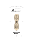
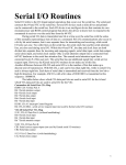
12.0 OPTION SWITCH SELECTION
51 - Modem Port Baud Rate
53 - Printer Port Baud Rate
NOTE: ONLY ONE SWITCH DOWN
9,600
4,800
2,400
1,200
600
300
150
2
3
4
5
6
7
8
9
10
75
110 baud
W14, 15, 16, 17
S1-~
S3
COMPOSITE VIDEO
- - - - - P2
P7-~"""'''''''''
W30
P5 -----IIIR28---1W26, 27, 28, 29
PAGE 1
W31
--.---+.....;
W32
W33
W34
- 1 - - - - PAGE 2
' - - - - - CRT CONTROLLER
CPU
PROGRAM ROM
22
12.152· UART/Terrninal Options
-..
Up
Down
Not used
Not allowed
2
~
,.Qowry
Alternate Character Set (option)
Standard Character Set
3
CJJp
Down
FULL DUPLEX
HALF DUPLEX
4
cgp '.
own
60 Hz - Refresh
50 Hz - Refresh
5
~ "
No Parity
Send Parity
Down
6
~.~
2 stop bits (may be used with No parity as space parity)
1 stop bit
Down
7
7
7
~
B (may be used with no parity as Mark parity)
B
Not used
9
10
number of Data Bits
Down
Parity Select
Up
(EVEN)
(ODD)
Steady Cursor
Blinking Cursor
~po~
12.255· UART/Terrninal Options
2
3,4
5
6, 7
Open
Closed
P3-6 Not connected
Data set ready (DSR) received on P3-6
Open
Closed
P3-B Not connected
Data Carrier Detect (DCD) received on P3-B
S5 - 3
S5-4
Open
Open
Open
Closed
P3-20 Not connected
Data Terminal Ready is on when the
terminal is ON.
Closed
Open
Data Terminal Ready (DTR) is connected
to Request to Send (RTS).
Closed
Closed
Not allowed
Not used
S5 - 6
S5 - 7
Open
Open
Closed
Closed
Open
Closed
Open
Closed
Not allowed
20 rna current loop input
RS232 input
Not allowed
23
OPERATOR CONTROLS
Main Port
Baud Rate
Transmission ---....:
Options
Contrast - - - -
ON/OFF Switch
---J
Printer Port - - - - - I
1.-
Main Port
......---115/220 volt switch
24
JUMPER OPTIONS
HALF-DUPLEX PASSIVE
HALF-DUPLEX ACTIVE
Current Loop
v
TVI·912/920
Install
Resistor
at
P3
P3
R·28
Install
Jumpers at·
251------j
W·6. W·14.
/loW·16
13
RCVR
13
Install
Jumper
at
Computer
W·16
XMTR
20mA
Source
12
12
24
f--------l
24
FULL DUPLEX PASSIVE
FULL DUPLEX, ACTIVE XMTR
Install
Jumpenat
P3
+12V
W·15/loW-17
100tall
Jumpers at:
RCVR
W·6. W·14.
/loW·16
13
Install
Resistor
at
20mA
Source
R-28
12
XMTR
20mA
XMTR
Source
24
,
i
t
20mA
Source
W31:
Installation of this jumper will enable an automatic line feed upon receipt of a carriage return
from the remote or keyboard.
W32:
Installation of this jumper will enable transmission of EDT at the end of Send, otherwise a CR
(carriage return) is sent.
r
I
RCVR
W33:
Installation of this jumper will disable the automatic CR (carriage return) line feed in Column
80.
W34:
Installation of this jumper will select Page Print Mode as the initial condition at power up.
Extension Mode will be selected otherwise.
25
CONTROL BOARD SWITCHES
S1 MODEM PORT BAUD RATE
S3 PRINTER PORT BAUD RATE
'-:;;~M--
110
75
150
300
600
1200
2400
4800
9600
Current Loop Select
RS232 Select
Not Used
Select DTR = Power ON
Select DTR = RTS (P3-201
Select DCD from P3-8
Select DSR from P3-6
P3
Down (Closed) Blinking
Up (Open) Steady
Select Odd Parity
No Connection
Select No. Data Bits
Select 1 Stop Bit (UP=2)
Select Send Parity
Select 50 Hz Refresh (Up=60)
Select Half Duplex (UP=Full)
Select Standard Characters
Always Up (Open)
Down
26
TERMINAL INTERIOR PHOTO
27
ADDRESSABLE CURSOR
..
POSITION
XorV
1
2
3
4
5
6
7
8
9
10
11
12
13
14
15
16
17
18
19
20
21
22
23
24
25
26
27
ASCII CODE
Transmitted
Space
!
"
#
$
%
&
,
(
)
...
+
,
/
0
1
2
3
4
5
6
7
8
9
CURSOR POSITIONING
POSITION
ASCII CODE
Xor V
Transmitted
28
29
30
31
32
33
34
35
36
37
38
39
40
41
42
43
44
45
46
47
48
49
50
51
52
53
54
,
<
=
>
?
@
A
B
C
D
E
F
G
H
I
J
K
POSITION
Xor V
55
56
57
58
59
60
61
62
63
64
65
66
67
68
69
70
71
L
72
M
N
P
73
74
75
76
Q
77
R
78
79
80
a
S
T
U
CU RRENT PAGE: Transmit ESC = YX (Y = 1-24; X = 1-80)
/
28
ASCII CODE
Transmitted
V
W
X
Y
Z
[
\
]
f\
,
a
b
c
d
e
f
9
h
i
j
k
I
m
n
0
ESCAPE SEQUENCES
010
011
100
101
110
111
2
3
4
5
6
7
SP
~
!
1
Extention
Print
Mode
Page
Print
Mode
@
Set Tab
A
P
Print Page
\
p
Q
Char
Insert
a
q
Line
Delete
b
r
c
s
d
t
U
e
u
f
v
Auto-Flip
On
g
w
Auto-Flip
Off
h
x
"
Keyboard
Unlock
2
Clear Tab
B
Set Block
Mode
R
#
Keyboard
Lock
3
Clear All
Tabs
C
Set Cony.
Mode
S
$
4
Send Line
Unprotected
D
%
5
Send Page
Unprotected
E
Protect
Mode On
6
Send Line All
F
V
Protect
Mode Off
7
Send Page All
G
W
(
Write
Protect Off
8
H
X
)
Write
ProtectOn
9
I
*
Clear All
to Nulls
+
Clear All
to Spaces
&
.
,
-
.
Clear FG
to Nulls
J
Clear FG
to Spaces
K
<
=
Line Insert
Char
Delete
y
Back Tab
Page Erase
to Spaces
Z
[
Toggle Page
\
]
M
Tab
y
j
Start
Reverse Video
z
k
End
Reverse Video
I
Start
Underline
m
I
>
A Start
N
Line Erase
to Nulls
i
I
L
Load Cursor
Line erase
to spaces
T
?
Read Cursor
0
-
29
Start
Blank
Page Erase
to Nulls
I
I
End
Underline
n
rv
0
DEL
Blink
/
End
Blink/Blank
I
I
TVI-912/920 ASCII CHART
~
0 0 0 0
0 0 0 1
0 0 1 0
0 0 1 1
0
0
0
0
1
1
1
1
1
1
1
1
1
1
1
1
0
0
0
0
1
1
1
1
0
0
1
1
0
0
1
1
0
0
1
1
0
1
0
1
0
1
0
1
0
1
0
1
•.
0
1
2
3
4
5
6
7
00
0
0
NUL
SOH
STX
ETX
EOT
ENQ
ACK
BEL
8
BS~
9
SKIP
HT
10
11
12
13
14
15
LF
.j.
VTt
FF -+
CR
SO
SI
00
1
1
DLE
DC1
DC2
DC3
DC4
NAK
SYN
ETB
CAN
EM
SUB
ESC
FS
GS
HOME
RS
NEW LINE
US
o1
0
2
SP
01
1
10
0
10
1
11
0
11
3
4
5
6
7
0
1
2
3
4
5
@
P
....
A
B
Q
a
P
q
R
b
C
S
c
r
s
D
E
d
t
F
e
f
u
9
v
w
(
6
7
8
T
U
V
W
X
h"
x
)
9
I
•
"
*
$
%
&
,
*
+
,
·
·
I
<
-
G
H
1
J
K
L
Z
[
]
•
>
M
N
/
?
0
30
•
Y
\
1\
J
k
I
m
n
0
y
z
{
}
~
DEL
RUB
1
OPERATOR'S QUICK REFERENCE
TVI-912/TVI-920 CONTROL
Function
Sequence
Beep
CTRL / G
Cursor +-- • • • • . . • . . • • • • • • • • • • • • • . • • • . • • . • • • • • . CTR L / H
Cursor ~ . . . . . . . . . . . . . . . . . . . . . . . . . . . . . . . . . . • . CTRL / J
Cursort
CTRL/ K
Cursor --+ . . • . • . • • • • • • • • . • . • • • . • • • • • • • • • • . • • • . CTR L / L
Home
CTRL / "-',1\
Tab (skip)
CTRL / I
New Line
CTR L /
(underscore)
Protect Mode On
ESC &
Protect Mode Off . . . . . . . . . . . . . . . . . . . . . . . . . . . . . . .. ESC '
Start (Half Intensity)
ESC )
End (Half Intensity)
ESC (
Set Column Tab. . . . . . . . . . . . . . . . . . . . . . . . . . . . . . . .. ESC 1
Clear Tab
ESC 2
Clear All Tab . . . . . . . . . . . . . . . . . . . . . . . . . . . . . . . . . .. ESC 3
Send Line Unprotect . . . . . . . . . . . . . . . . . . . . . . . . . . . . .. ESC 4
Send Page Un protect . . . . . . . . . . . . . . . . . . . . . . . . . . . . .. ESC 5
Send Line All. . . . . . . . . . . . . . . . . . . . . . . . . . . . . . . . . .. ESC 6
Send Page All. . . . . . . . . . . . . . . . . . . . . . . . . . . . . . . . . .. ESC 7
ESC +, ESC Z
Clear All to Space
ESC *
Clear All to Null
Clear FG to Null. . . . . . . . . . . . . . . . . . . . . . . . . . . . . . . .. ESC
CTRLlZ, ESC
Clear FG to Space
Keyboard Enable .. . . . . . . . . . . . . . . . . . . . . . . . . . • . . .. ESC ..
Keyboard Disable . . . . . . . . . . . . . . . . . . . . . . . . . . . . . . .. ESC #
Load Cursor
ESC
ESC ?
Read Cursor
Set Block Mode . . . . . . . . . . . . . . . . . . . . . . . . . . . . . . . .. ESC B
Set Conversation Mode
ESC C
Print Page . . . . . . . . . . . . . . . . . . . . . . . . . . . . . . . . . . . .. ESC P
Char Insert
ESC Q
Char Delete . . . . . . . . . . . . . . . . . . . . . . . . . . . . . . . . . . .. ESC W
Line Insert
ESC E
Line Delete . . . . . . . . . . . . . . . . . . . . . . . . . . . . . . . . . . .. ESC R
Line Erase to Space. . . . . . . . . . . . . . . . . . . . . . . . . . . . . .. ESC T
ESC Y
Page Erase to Space
Back Tab
ESC I
Toggle Page
, ESC K
Start Blink Field. . . . . . . . . . . . . . . . . . . . . . . . . . . . . . . .. ESC 1\
Start Blank Field
ESC
(underscore)
End Blink/Blank
ESC q
Tab
ESC
Start Inverse
ESC j
End Inverse
ESC k
Start Underline
ESC I
End Underline
ESC m
Line Erase to Null. . . . . . . . . . . . . . . . . . . . . . . . . . . . . . .. ESC t
Page Erase to Null. . . . . . . . . . . . . . . . . . . . . . . . . . . . . . .. ESC y
Auto Flip On
ESC v
Auto Flip Off
ESC w
Extension Port On
ESC @
Page Print Mode On
ESC A
31
""0»
~q/)
TELEVIDEO, INCORPORATED
3190 Coronado Drive
Santa Clara, California 95051
(408) 246-5428/TWX: 9103387633