1
Te/eVideo® Model925
CRT Termina//nsta//ation
and User's Guide
o®TeleVideo Systems, Inc.
Vital Statistics
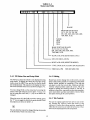
When you receive your terminal, enter here the serial number (on rear panel), date received, and switch settings. This
will expedite any technical conversations about your terminal.
Serial Number _ _ _ _ _ _ _ _ __
Date Received _ _ _ _ _ _ _ _ __
Switch Settings Used:
(Enter U or D for Up or Down)
Sl
UID
UID
1_
1_
S2
U/D
S3
1_
2_
3_
4_
5_
6_
7_
8_
9_
2_
3_
4_
5_
6_
7_
8_
9_
2_
3_
4_
5_
6_
7_
8_
9_
10_
10_
10_
Disclaimer
TeleVideo Systems, Inc. makes no representations or warranties with respect to this manual. Further, TeleVideo
Systems, Inc. reserves the right to make changes in the specifications of the product described within this manual at
any time without notice and without obligation of TeleVideo Systems, Inc. to notify any person of such revision or
changes.
TELEVIDEO SYSTEMS, INC.
1170 Morse Avenue
Sunnyvale, California 94086
4081745-7760
"Warning: This equipment generates, uses, and can radiate radio frequency energy, and if not installed and used in
accordance with the instruction manual may cause interference to radio communications. As temporarily permitted
by regulation, it has not been tested for compliance with the limits for Class A computing devices pursuant to Subpart
J of Part 15 of FCC Rules, which are designed to provide reasonable protection against such interference. Operation
of this equipment in a residential area is likely to cause interference, in which case the user at his own expense will be
required to take whatever measures may be required to correct the interference."
MODEL 925 OPERATOR'S MANUAL
Specifications and Information SUbject to Change
Without Prior Notification
TeleVideo No. B300013-001
RevisionB
Copyright TeleVideo Systems, Inc.
19 May 1982
Copyright © 1982 by TeleVideo Systems, Inc. All rights reserved. No part of this publication may be reproduced,
transmitted, transcribed, stored in a retrieval system, or translated into any language or computer language, in any
form or by any means, electronic, mechanical, magnetic, optical, chemical, manual, or otherwise, without the prior
written permission of TeleVideo Systems, Inc., 1170 Morse Avenue, Sunnyvale, California 94086.
TABLE OF CONTENTS
WARRANTY POLICY AND RETURNED
MATERIAL PROCEDURE
SPECIFICATIONS
iii
iv
1. INTRODUCTION
1.1 Description of Manual
1.2 How to Use This Manual
1.3 Description of Terminal
1.4 Protect Yourself!
1.5 Protect the Terminal
1
1
1
1
2
2. INSTALLATION
2.1 Introduction
2.2 Unpacking and Inspecting the Terminal
2.2.1 Shipping Damage Inspection
2.2.2 Unpacking the Terminal
2.2.3 Inspecting the Terminal
2.2.4 Reporting Damage
2.2.5 Reshipping the Terminal
2.3 Preparing the Site
2.3.1 Power Requirements
2.3.2 Physical Requirements
2.4 Installation
2.4.1 Power Configuration
2.4.1.1 115 VAC Configuration
2.4.1.2 230 VAC Configuration
2.4.1.3 Setting Power Select Switch
2.4.2 Connecting the Terminal to
Your Computer System
2.4.3 Interfacing to a Printer
2.4.4 Configuring the Terminal for
the Computer and Printer
2.4.4.1 Character Sets
2.4.4.2 Video Display
2.4.5 Composite Video Jumper Option
2.4.6 Two-Page Memory Option
2.4.7 Additional Field Modifications
2.5 Checking Your Installation
3. OPERATION
3.1 Introduction
3.2 Turning On the Terminal
3.2.1 Rear Controls
3.2.2 Turning On the Terminal
3.3 Keybaord Controls
3.3.1 Keyboard Layout
3.3.2 Other Controls
3.3.2.1 Cursor
3.3.2.2 Cursor Addressing
3.3.2.3 Bell
3.3.2.4 Break
3.4 Basic Operations
3.4.1 925 Status Line and Setup Mode
3.4.2 Editing
3.4.3 Tab Controls
3.4.4 Emulations
3.4.5 Transmission Modes
3.4.5.1 Conversation Mode
3.4.5.1.1 Half Duplex Mode
3.4.5.1.2 Full Duplex Mode
3.4.5.2 Block Mode
3.4.6 Sending Data to the Printer
4. PROGRAMMING
4.1 Introduction
4.2 Monitor Mode
4.3 Function Keys
4.4 FUNCT (Function) Key
4.5 Addressing and Reading the Cursor
4.5.1 Addressing the Cursor
4.5.2 Reading the Cursor
4.6 Video Attributes
16
4.7 Tabs
17
4.7.1 Setting Tabs (ESC 1)
17
4.7.2 Using Tabs
17
4.7.2.1 Typewriter Tab (Protect and
Unprotect) (CTRUI)
17
4.7.2.2 Field Tab (Protect Only) (ESC i)
17
4.7.2.3 Back Tab (ESC I)
17
4.7.3 Clearing Tabs
18
4.8 Protect Mode
18
4.8.1 Application
18
4.8.2 Effect
18
4.8.3 Procedure
18
4.8.3.1 Input
18
4.8.3.2 Protection
18
4.9 Editing Control
18
4.9.1.1 Set Local Edit Mode
18
4.9.1.2 Set Duplex Edit Mode (ESCI)
19
4.9.2 Cursor Control
19
4.9.2.1 Cursor Control Codes
19
4.9.2.2 Normal and Reverse Linefeed
19
4.9.2.3 Editing Commands
20
4.9.2.4 Clear Function
20
4.10 Send Function
20
4.10.1 Send Line Unprotected (ESC 4)
20
4.10.2 Send Page Unprotected (ESC 5)
20
4.10.3 Send Line All (ESC 6)
20
4.10.4 Send Page All (ESC 7)
21
4.10.5 Send Message Unprotected (ESC S)
21
4.10.6 Send Message All (ESC s)
21
4.11 Termination Character Selection
21
4.12 Print Function Programming
21
4.12.1 Page Print (ESC P)
21
4.12.2 Transparent Print On (ESC' )
21
4.12.2.1 Transparent Print Off (ESC a)
21
4.12.3 Extension Mode On (ESC@)
21
4.12.4 Extension (Copy Print) Mode Off (ESC A)21
4.12.5 Enable Bidirectional Port (CTRUR)
21
4.12.5.1 Disable Bidirectional Port (CTRLrr)
22
4.12.6 Send Time of Day
22
4.12.7 Printer Termination Character
22
4.13 X-ONIX-OFFControl
22
4.14 DTR Control
22
4.15 Time of Day Clock
22
22
4.16 Keyboard Keyclick
4.17 Disabling the Keyboard
22
4.18 Screen Time Out
23
4.19 Page Control
23
4.20 User Line
23
4.20.1 To Load the User Line
23
4.20.2 Entering Data
23
4.21 912/920C Emulation
23
4.22 Cursor Attributes
23
23
4.23 Screen orr
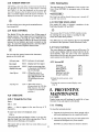
5. PREVENTIVE MAINTENANCE
23
5.1 Care
23
5.1.1 Cleaning
23
5.1. 2 Inspection
23
2
2
2
2
2
2
2
3
3
3
3
3
3
3
3
3
5
5
6
6
6
6
6
6
6
6
6
7
7
7
11
11
11
11
11
11
12
12
12
14
14
14
14
14
14
14
14
14
14
15
15
15
15
16
6. TROUBLESHOOTING AND REPAIR
6.1 Troubleshooting
6.1.1 Testing the Terminal (Self Test)
6.2 Repair
6.2.1 Changing the Line Fuse
6.2.2 Changing the Power Supply Fuses
TROUBLE SHOOTING CHART
GLOSSARY
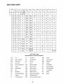
US ASCII CHART
ii
24
24
24
24
24
24
25
27
29
LIMITED WARRANTY AND RETURNED MATERIAL PROCEDURE
STATEMENT OF LIMITED \VARRANTY
TeleVideo Systems, Inc. ("TeleVideo") warrants to Buyer that products, except software, manufactured by TeleVideo
will be free from defects in material and workmanship. TeleVideo's obligations under this warranty will be limited to
repairing or replacing, at TeleVideo's option, the part or parts of the products which prove defective in material or
workmanship within 90 days after shipment by TeleVideo, provided that Buyer gives TeleVideo prompt notice of any
defect and satisfactory proof thereof. Products may be returned by Buyer only after a Return Material Authorization
number ("RMA") has been obtained from TeleVideo by telephone or in writing. Buyer will prepay all freight charges
to return any products to the repair facility designated by TeleVideo and include the RMA number on the shipping
container. TeleVideo will deliver replacements for defective products or parts on an exchange basis to Buyer, freight
prepaid to the Buyer. Products returned to TeleVideo under this warranty will become the property of TeleVideo. With
respect to any product or part thereof not manufactured by TeleVideo, only the warranty, if any, given by the manufacturer thereof, will apply.
EXCLUSIONS
This limited warranty does not cover losses or damage which occurs in shipment to or from Buyer or is due to (1)
improper installation or maintenance, misuse, neglect or any cause other than ordinary commercial or industrial
application or (2) adjustment, repair or modifications by other than by TeleVideo-authorized personnel or (3) improper
environment, excessive or inadequate heating or air conditioning and electrical power failures, surges or other irregularities or (4) any statements made about TeleVideo's products by salesmen, dealers, distributors or agents, unless
confirmed in writing by a TeleVideo officer.
THE FOREGOING TELEVIDEO LIMITED WARRANTY IS IN LIEU OF ALL OTHER WARRANTIES,
WHETHER ORAL, WRITTEN, EXPRESS, IMPLIED OR STATUTORY. IMPLIED WARRANTIES OF MERCHANTABILITY AND FITNESS FOR A PARTICULAR PURPOSE WILL NOT APPLY. TELEVIDEO'S WARRANTY OBLIGATIONS AND BUYER'S REMEDIES HEREUNDER ARE SOLELY AND EXCLUSIVELY AS
STATED HEREIN. TELEVIDEO MAKES NO WARRANTY WHATSOEVER CONCERNING ANY SOFTWARE PRODUCTS, WHICH ARE SOLD "AS IS" AND "WITH ALL FAULTS."
TELEVIDEO'S LIABILITY, WHETHER BASED ON CONTRACT, TORT, WARRANTY, STRICT LIABILITY
OR ANY OTHER THEORY, SHALL NOT EXCEED THE PRICE OF THE INDIVIDUAL UNIT WHOSE DEFECT OR DAMAGE IS THE BASIS OF THE CLAIM. IN NO EVENT SHALL TELEVIDEO BE LIABLE FOR
ANY LOSS OF PROFITS, LOSS OF USE OF FACILITIES OR EQUIPMENT, OR OTHER INDIRECT, INCIDENTAL OR CONSEQUENTIAL DAMAGES.
Service Out of Warranty
If your terminal is out of warranty when it needs service, you should follow the same procedure to receive an RMA.
You will be responsible for all shipping costs.
Should your company require a purchase order for out-of-warranty repairs, let us know the purchase order number
when you call in. One purchase order may cover several repairs but we will give each item its own individual RMA
number. This allows us to return each item quickly and not hold up the entire purchase order because of one item.
Technical Assistance (Other than Repair)
The Technical Marketing Support Group is normally open from 8:00 a.m. until 5:00 p.m., Pacific Time, continuously,
Monday through Friday. If the line is busy and your problem can wait, leave a message with the Tele Video operator
and your call will be returned at our first opportunity.
Extended Warranty
TeleVideo offers an Extended Warranty Contract. To take advantage of this Extended Warranty, you must sign the
Extended Warranty Contract and return it, together with full payment, to TeleVideo prior to the end of your normal
warranty period. The extended warranty lasts for one year; the cost is $75.00.
To renew the extended warranty for another year, the same procedure must be followed.
Shipping charges are not included in the Extended Warranty. This is the only expense you incur.
III
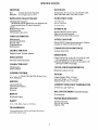
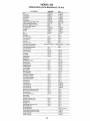
SPECIFICATIONS
MONITOR
BAUD RATE
Size:
Pliosphor:
15 baud rates: 50, 75, 110, 135, 150,300,600, 1200,
1800,2400,3600,4800,7200,9600,19,200
12 inches measured diagonally
P31 nonglare green screen
DISPLAYED CHARACTER SET
WORD STRUCTURE
128 displayable characters
(96 character ASCII upper/lower case alphabet with
true descenders plus 32 control characters)
24 lines
80 characters per line
25th Status Line
1920 characters per screen
7 or 8 data bits
One or 2 stop bits
10-11 bit word
INTERFACES
Standard RS232C point-to-point
20m a current loop (optional)
RS232C printer port (bidirectional)
VIDEO ATTRIBUTES
AUXILLIARY PORT
Blinking fields
Security (blank) fields
Reverse video
Underlined fields
Half intensity
Printer RS232C, bidirectional, page print, buffered
transparent, buffered with screen copy
COMMUNICATION PROTOCOL
CHARACTER SETS
X-ON/X-OFF, DTR
English, French, German, Spanish
DIMENSIONS
EMULATIONS
Cabinet dimensions: 16.50" (41.9 cm) wide X 14.00"
(35.6 cm) deep X 14.25" (36.2 cm) high
Keyboard dimensions: 16.50" (41.9 cm) wide X 7.50"
(19.0 cm) X 3.00" (7.6 cm) high
TeleVideo 912/920 terminals
CHARACTER FONT
7X8 dot matrix
8X10 resolution
VENTILATION REQUIREMENTS
CURSOR CONTROL
i , !, +- , -+ ,Home, Tab, Back Tab, Return, Line
WEIGHT
Minimum 4 inches (10.2 cm)
Cabinet Weight: 301bs. (13.6 kg)
Keyboard Weight: 4.5Ibs. (2.04 kg)
Shipping Weight: 44 ibs. (19.96 kg)
Feed, Backspace
EDITING
AMBIENT OPERATION TEMPERATURE
Line insert/delete
Character insert/delete
Line scroll
No Scroll
320 F (00 C) to 1220 F (500 C)
REPEAT
No restrictions
RELATIVE HUMIDITY (nonoperating)
20-cps auto-repeat
POWER REQUIREMENTS
PARITY
115 VAC at 0.5 amp
230 VAC at 0.25 amp
50/60 Hz, SSW
Even, Odd, Mark, Space or No Parity
TRANSMISSION
Conversation mode: Full or half duplex (keyboard
selectable), Block mode
iv
General note giving information
to every operator.
1. INTRODUCTION
DII[]IE"~~~;]!C:>-
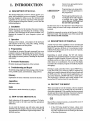
1.1 DESCRIPTION OF MANUAL
This manual will teach you how to install, operate, program, and troubleshoot your new terminal. The manual
has been designed to help you use the terminal easily
regardless of your previous experience with terminals.
As you progress through the manual, you will find the
following chapters:
s
Programming note giving information of special significance to
the programmer.
Warning giving information concerning the safety of the operator
or possible loss of data. When
you see this note, STOP and read
the note before proceeding!
On the back cover is the Operator's Quick Reference
Guide, listing all control and escape commands for the
terminal.
2. Installation
Setting up your site for the terminal, the power requirements, unpacking and checking the terminal, setting
switches to take advantage of the options available, configuring the terminal for your computer system and
printer.
Emulation commands are given in the Operator's Quick
Reference Guide. The descriptive text of the manual will
only reference the 925 commands.
3. Operation
1.3 DESCRIPTION OF TERMINAL
Turning on the terminal, a description of the keyboard
and functions of the keys, using tabs, editing, sending
data to the computer and the printer.
A brief overview of the capabilities of your terminal will
help you take advantage of its features as you use it. The
Model 925 operates in Block or Conversational modes
(HDX, FDX). Baud rates can be set at any of 15 speeds,
from 50 to 19,200 bps.
4. Programming
Controlling the terminal through commands from your
computer system: programming special functions, setting visual attributes, monitoring the program, loading
and reading the cursor position, disabling the keyboard
and printer.
Depending on switch settings, the 925 will emulate
TeleVideo's 912 and 920 terminals. Character sets can be
changed to English, Spanish, German, or French. Visual
attributes can be set a line at a time, or a page at a time,
either alone or in combination. You can set the display
to monitor the computer program (to facilitate program
debugging) .
5. Preventive Maintenance
Periodic cleaning and inspection of the terminal.
6. Troubleshooting and Repair
Printing is easily controlled with a special PRINT key.
Using the FUNCT key with any alpha or numeric key
allows you to quickly transmit the key selected bracketed
by SOH and a CR. To create custom applications, you
can easily substitute a ROM with twice as much space.
The keyboard is a Selectric style which includes a tenkey pad and 22 function keys for easy data entry.
Troubleshooting simple problems (using a table of symptoms, possible causes, and solutions), using self-test.
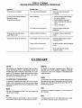
Glossary
Explanation of terms commonly used in this manual.
Appendices
Reference tables.
1.4 PROTECT YOURSELF!
Index
When you install or test the terminal, observe standard
safety precautions (as you would with any electrical or
electronic equipment). Only qualified service personnel
should open the terminal housing. Disconnect all power
before performing any inspection or maintenance.
References to main subsections by subject.
1.2 HOW TO USE THIS MANUAL
S
Each subsection of the manual is numbered. To find a
topic later, look in the index and find the appropriate
subsection.
Beyond the normal precautions, you should be aware of
two additional conditions:
As you read the manual, you will notice some special
symbols at the left margin of the text. These symbols call
your attention to information of special importance. The
symbols used are:
1. If the CRT tube should be broken, always wear
heavy rubber gloves or use tongs to pick up the broken CRT fragments since the coating on the inside
of the tube is poisonous.
1
2.2.3 Inspecting the Terminal
2. Even after the power is turned off, charges are retained by the CRT and capacitors. Always discharge them to ground before touching them.
Never reach into the terminal enclosure unless
someone capable of giving aid is present.
After you unpack the terminal, inspect it thoroughly for
hidden damage and loose components or fittings. The
inspection checklist is as follows:
1. Remove the terminal cover by removing the screws
underneath the front bottom and the rear of the
terminal. Lift up the cover carefully.
1.5 PROTECT THE TERMINAL
Although the terminal is packaged in a durable housing,
you can help protect it by observing two simple
precautions:
2. Inspect the keyboard and display cabinet interior
for shipping damage.
1. Take care to keep foreign objects such as paper
clips or liquids off the keyboard.
3. Examine cable harnesses for stress, loose or broken wires, or broken cable ties.
2. Use the terminal on a secure surface and don't drop
the terminal or drop heavy objects onto it.
4. Examine all internally mounted components for
loose or missing hardware.
5. Tighten all loose hardware.
2. INSTALLATION
6. Clean loose debris from the cabinet interior.
7. Replace the cover. Do not overtighten the screws.
2.1 INTRODUCTION
This chapter will tell you how to unpack and check your
terminal for damage, check power and site requirements, and set the power and interface configurations.
A brief checklist at the end will make sure you did not
skip any part of the installation process.
2.2.4 Reporting Damage
If hidden damage is found, immediately notify the transfer company of the damage. Save all packing materials
for the transfer company's inspection, file a damage report with the carrier, and notify your dealer and
TeleVideo of the damage. Since terms of sale for the
terminal are FOB TeleVideo, Sunnyvale, California,
TeleVideo is not responsible for any damage which occurred during shipment and will not repair this damage
under warranty. All repairs for shipping damage are billable. Prompt notification of damage will ensure claim
validity and expedite payment for necessary repairs by
the transfer company or its insurance agent.
Once your terminal is installed, you will be ready to operate the terminal and you will probably not need to use
this chapter again unless you need to move the terminal,
reship it, or use it with another computer system.
As you start the installation, you will want to have some
information about your computer system and its configuration requirements.
2.2.5 Reshipping the Terminal
2.2 UNPACKING AND INSPECTING
THE TERMINAL
Should you need to reship the terminal, follow these
procedures:
2.2.1 Shipping Damage Inspection
1. Remove the two screws on the bottom front and
bottom rear of the terminal and lift off the cover.
After the terminal is delivered to you, inspect the shipping container as weB as the terminal (inside and out) for
damage before taking it to your installation site. You
should inspect the container for obvious damage before
accepting delivery of the terminal. If damage is found,
note it on the waybill and require the delivery agent to
sign the waybill. Notify the transfer company immediately and submit a damage report to the carrier, your
dealer, and to Tele Video. If no exterior damage is found,
unpack the terminal and inspect it for hidden damage.
2. Check the integrity of the cabling and security of
internal mounting hardware.
3. Replace cover, being careful not to overtighten the
screws.
4. Repack the terminal in the original Tele Video shipping container or other suitable materials.
2.2.2 Unpacking the Terminal
5. Put the RMA number on the outside of the box.
Carefully unpack the terminal from the shipping container. Avoid using sharp instruments to open the container. Save the packing material for possible use in
reshipping the terminal.
2
2.3 PREPARING THE SITE
2.4.1.2 230 VAC Configuration
Before you proceed with the actual installation, make
sure you are ready with the proper power and a large
enough table.
If you are located outside the United States and use 230
VAC power, cut off the US-style three-prong plug provided and install a connector compatible with your local
power receptacles. The power cord wires are color
coded as follows:
2.3.1 Power Requirements
• 115 VAC 60 Hertz at 0.5 amp
OR
230 VAC 50 Hertz at 0.25 amp
• Green
Earth ground
• Black
Primary power (hot)
• 55 watts
• White
Primary power return (neutral)
2.4.1.3 Setting Power Select Switch
• NEMA standard 5-15R, 3-prong receptacle (US
only)
Set the power select switch on the bottom of the terminal
to either 115V or 230V. You will set Hertz to match your
power frequency when you set S2.
2.3.2 Physical Requirements
• Flat, level area:
• Surface dimension:
13V4" H X 16 1/g" W X 20V16" D
33.66 cm H X 40.96 cm W X
50.96cmD
2.4.2 Connecting the Terminal to Your
Computer System
13V2" H X 16Vg" W X 20 1/16" D
33.66 cm H X 40.96 cm W X
50.96cm D
You can connect the terminal directly to your computer
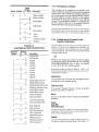
system or use a modem. Table 2-1 points out pin connections which are always used for either the computer connection or to a modem.
Refer to Figure 2-1
Interfacing Connections-The interface connection to
the computer system (main) port is P3, located on the
rear of the terminal. The connector configuration of P3
is given in Table 2-1.
• Recommended ventilation clearance is 4 inches
(10.2 cm) on all sides.
2.4 INSTALLATION
TABLE 2-1
P3 (COMPUTER INTERFACE)
CONNECTOR
The actual installation and set-up consists of only three
steps:
1. Configuring the terminal for either 115 or 230 VAC
operation.
PIN No.
1
2
3
4
5
6
7
8
20
9
14
10
25
13
12
24
2. Configuring and connecting the terminal to the
computer and printer connectors.
3. Setting up the terminal's operating switches and
jumper options.
These procedures should only be performed by technically qualified personnel.
2.4.1 Power Configuration
Depending on your location, the terminal can be configured to operate with either 115 VAC (United States) or
230 VAC (international).
2.4.1.1 115 VAC Configuration
Keep the three-prong plug which is provided with the
terminal and make sure your outlet is grounded. If an
adapter is used, ground with a pigtail.
SIGNAL NAME
Frame Ground
Transmit Data Output
Receive Data Input
Request To Send Output
Clear To Send Input
Data Set Ready Input (opt.)
Signal Ground
Carrier Detect Input
Data Terminal Ready Output
20 rnA source ( + 12V, no load)
20 rnA source ( + 12V, no load)
Detected current loop data
Current Loop + , Transmit
Current Loop - , Transmit
Current Loop + , Receive
Current Loop - , Receive
(Reference EIA Standard RS232 for Signal Definitions)
3
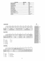
TABLE 2-3
EXTERNAL SWITCH SETTINGS FOR
MODEL 925
TABLE 2-2
SERIAL PRINTER INTERFACE (P4)
PIN CONNECTIONS
PIN No.
SIGNAL NAME
1
2
Switch
Sl
7
1
Protect Ground
Receive Data
Transmit Data
Request To Send
Clear To Send
Data Set Ready
Signal Ground
Data Carrier Detect
Data Terminal Ready
3
4
5
6
7
8
20
D
D
D
D
D
D
D
D
U
U
U
U
U
U
U
U
~~
¥.~.,
Legend:
Position
8
9
2
3
D
D
D
D
D
U
D
U
D
U
U
D
U
U
U
U
D
D
D
D
D
U
D
U
U
D
U
D
U
U
U
U
10
4
D
U
D
U
D
U
D
U
D
U
D
U
D
U
D
U
Baud Rate
Setting
[Printer ]
[Main RS232]
9600
50
75
110
135
150
300
600
1200
1800
2400
3600
4800
7200
9600
19200
U = Up
D = Down
NOTES
I~·
1. Set to match powerline frequency to avoid screen flicker.
Toggle
Switch
Sl
Position
Up
5
X
6
X
1
X
X
X
S2
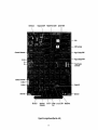
Figure 2-1 Model 925 Dimensions
X
2
X
X
X
X
X
X
X
3
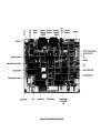
S-2
P-6
P-4
P-3
4
5
S-1
3
4
5
3
4
5
3
4
5
3
4
5
Figure 2-2 925 Rear Panel
4
Settin~
Down
Description
7-bit word
8-bit word
2 stop bits
1 stop bit
Local Edit
Duplex Edit
(transmit editing keys)
912/920 emulation
925
No parity
Odd Parity
X
X
X
X
X
Even Parity
X
X
X
X
X
Mark Parity
Space Parity
Switch Position
S2
6
X
X
X
X
7
8
7
X
8
X
X
7
8
X
9
10
2.4.3 Interfacing to a Printer
Toggle
Setting
Up Down Description
X
X
X
X
Your terminal can be connected to an auxiliary serial
printer to make a permanent hard copy of data displayed
on the screen. The terminal's serial printer interface allows the terminal to be used with most RS232-compatible serial printers currently available on the market,
including both character-by-character and buffered
printers. The serial printer interface is a 25-pin connector, P4, located on the rear of the terminal. Table 2-2
defines the printer interface pin connections.
White on Black
Black on White
Half Duplex
Full Duplex
Sl and S2 are accessible from the rear of the terminal.
[S3 internal switch is only accessible by removing the
four cabinet screws (see 2.2.3) and removing the cover.]
Block Mode
50Hz I
60Hz I
CRiLF (Auto LF)
CRonly
2.4.4 Configuring the Terminal for the
Computer and Printer
Several switches, located at the rear and internally (see
Figure 2-2), allow you to configure the terminal to operate according to the requirements of your computer
system and printer. This section lists all possible switch
settings (in table form).
TABLE 2-4
S3 INTERNAL SWITCH SETTINGS
Dipswitch
Number
1
2
3
2
3
2
3
2
3
Position
DN
UP
X
X
X
X
X
X
X
X
X
X
4
5
4
5
4
5
4
5
X
X
6
X
X
X
X
X
X
X
X
7
X
8
X
9
X
X
X
X
10
X
X
Description
Keyc1ick Off
Keyc1ick On
English
English
German
German
French
French
Spanish
Spanish
,1/
-0/1'
Whenever you change any switches, reset the terminal
by turning the power off and then back on or pressing
SHIFf/BREAK/BREAK keys to allow the software
to scan all of the new switch positions.
Setting the switches as shown in Tables 2-3 and 2-4 allows you to preset the terminal to operate in any of several optional conditions:
Baud Rates
You can select any of 15 baud rates according to the requirements of your computer system.
Blinking Block Cursor
Blinking Block Cursor
Blinking Underline Cursor
Blinking Underline Cursor
Steady Block Cursor
Steady Block Cursor
Steady Underline
Steady Underline
Character Sets
You can select English, French, German, or Spanish
character sets. Refer to Table 2-4.
Hertz
You can set the Hertz switch to match your powerline
frequency.
Time out blank (ON)
Time out blank (OFF)
Parity
Stop Bits
Word Structure
Page Attributes
Line Attributes
DCD Disconnected
DCD Connected
DSR Disconnected
DSR Connected
DTR Disconnected
DTR Connected
You can set the parity, number of stop bits, and number
of data bits in the word structure to match the requirements of your computer system.
Signals
You can connect/disconnect Data Set Ready, Data Carrier Detect, and Data Terminal Ready. (See Table 2-4.)
5
Power Supply
Connector P-5 - - - - - - - - - - - - ,
r----- Logic Board
Video Monitor
. - - - - - - - - - - - Connector P-2
Fuses
-------------------~
Power Supply - - - - - - _
Video Monitor
Figure 2-3 Terminal Interior
Sa
Shift Clock
Keyboard UART
RS232/Printer UART
System ROM
CPU
CRT Controller
Character Generator
Page 1 Display RAM
Page 2 Display RAM
Power Supply
Connector
Monitor Connector
P2 Pin3
SwitchS3
Switch S1
Figure 2-4a Logic Board (Part No. -001)
5b
SwitchS2
Switch S1
P2 Pin 6 Composite Video
Monitor Connector
_ _ _ E1
E2
. o f - - - Speaker
Modem Connector
Main and Printer Port UART - - ! ! -
E3
E4
Page 1 Display RAM
Keyboard UART
'4----System Gate Array
Power Supply Connector
--@io
System RAM
CPU
System ROM
CRT Controller
Optional Page 2
Display RAM
A33
Figure 2-4b Logic Board (Part No. -002)
2. To disconnect DTR from the printer (pin 20 on P4),
cut the trace between E10 and Ell.
2.4.4.1 Character Sets
The 925 has four possible character sets, controlled by
S3. The standard set is English. To select another character set, refer to Table 2-4.
3. To control DTR output (pin 20 on P3) with RTS output (pin 4 on P3), cut the trace between E15 and E16
and install a jumper between E14 and E16.
2.5 CHECKING YOUR INSTALLATION
Before you proceed to the next chapter and turn on the
terminal, check to be sure you installed the terminal
correctly.
Character sets are resident in the character generator.
You must reprogram the terminal system ROM for the
particular keyboard layout desired.
1. Did you install the correct power plug for your wall
outlet?
2.4.4.2 Video Display
You can set the display of the terminal to. be. green on
black or black on green, with a steady or bhnkmg cursor
which is either an underline or a block.
2. Did you set the power selector switch to match your
power requirements?
3. Is the main interface cable to the computer system
properly wired and plugged in?
2.4.5 Composite Video Jumper Option
To drive a monitor in addition to the terminal monitor,
you can modify the 925 logic board. The logic board's
part number may be labeled -001 (Figure 2-4a) or -002
(Figure 2-4b). The modification instructions for the composite video jumper are the same, regardless of the logic
board designation.
4. If you are using a printer, did you plug in the printer
interface connector?
5. Did you set the switches for the correct
• baud rate (both for terminal and printer)?
• stop bits?
• word structure?
• parity?
The modifications needed are as follows:
1. Add a BNC connector to the back panel.
6. Did you set switches for
2. Connect the center lead to P2 pin 6; connect the ground
lead of the BNC connector to P2 pin 3.
• 50 or 60 Hertz (to match your powerlinel
frequency requirements)?
• full or half duplex?
3. Cut the trace between E3 and E4 and install a jumper
between E1 and E2.
7. Did you plug the terminal in to the wall outlet?
2.4.6 Two-Page Memory Option
If the answers are YES, then you are ready to proceed
with actually using the terminal.
You can add one additional page of display memory to
the 925. This is not normally factory-installed. Follow
these steps to install this option:
3. OPERATION
1. Unplug the terminal and remove the top cover.
3.1 INTRODUCTION
2. Install a 6116 2KX8 bit 150 NS RAM chip onto the
control board. If the logic board is labeled -001, install the chip in position A48. If the board is labeled
-002, install it in position A33.
This chapter will lead you step-by-step through the operation of the terminal. Even if you have never used a
computer terminal before, you will be able to use the
terminal easily if you read this chapter carefully. If you
are a programmer, you will want to continue on to Chapter 4, which covers additional information for programming a computer to interface with your terminal.
The notch on the chip should face the same direction
as the notches on the other chips. Be careful not to
bend the pins.
During this chapter you will learn about:
3. Check the notch position again before installing the
cover and turning on power again.
• Turning on and adjusting the terminal's display
screen
2.4.7 Additional Field Modifications
• Using the various keys on the keyboard
The following field modifications may also be made. The
directions given in this section apply to boards labeled
-001 or -002.
• Directing data to the computer system and the
printer through send commands.
• Setting tabs
1. For handshaking, use pin 4 (on P4) rather than pin 11
on P4. Cut the t.e between E6 and E7 and install a
jumper from E5 to E7.
• Changing visual attributes of the screen
• Communicating with your computer system
6
4. If the cursor does not appear at the HOME position, press the HOME key on the keyboard. If the
cursor still does not appear, check the contrast control at the rear of the terminal (Figure 2-2).
3.2 TURNING ON THE TERMINAL
3.2.1 Rear Controls
Several controls are located at the rear of the terminal
(see Figure 2-2)
5. Ad just the contrast control for the desired screen
intensity.
• Baud rate switches (Sl)
6. Adjust the tilt of the screen by unscrewing the leg
in the center front.
• Function switches (S2)
7. Follow the sign-on protocol required by your
computer system.
• Internal Switch (S3)
8. See Chapter 6, Troubleshooting and Repair, for help
if the installation does not proceed smoothly.
Set these prior to turning on power to the terminal (as
explained in 2.4.4, and keep a permanent record on page
iv of how you have set the switches.
3.3 KEYBOARD CONTROLS
The connectors to the main interface and printer ports
are also located here.
In addition to standard alphanumeric typewriter keys,
your terminal has several keys which perform special operations. These special keys can be used in conjunction
with your computer to allow:
• Modifying action of other keys
Once these have been set during installation, they will
seldom need to be changed unless the terminal is being
used with several different computer systems.
• Editing
• Entering preprogrammed data
3.2.2 Thrning On the Terminal
Each key on the keyboard is actually a switch. Sometimes two keys can be used together to provide a totally
different message to the computer (CTRL or SHIFT).
When used together, these keys control the generation
of data sent to the computer system and the receipt and
printing of information.
Turn on the terminal as follows:
1. Make sure the ON/OFF switch at the back of the
terminal (Figure 2-2) is OFF.
2. Plug the terminal cord into a grounded outlet (115
VAC in United States).
3.3.1 Keyboard Layout
3. Push the end of the rocker power switch marked
with a white dot. The terminal should beep within
one second, indicating that power is on and the
CPU has initialized the terminal. After another 10
to 15 seconds, the cursor should appear in the upper left corner of the screen (HOME).
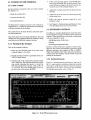
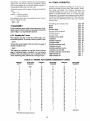
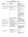
Figure 3-1 illustrates the keyboard layout. ,Refer to Table 3-1, where each key's function is described in detail.
This table is subdivided by types of functions and gives
information on the effect of each key and commands.
For detailed information, refer to Tab-Ie 3-1.
Figure 3-1 Model 925 Keyboard Layout
7
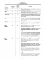
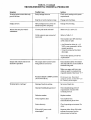
TABLE 3-1
FUNCTION OF KEYS
Key Name
Transmitted?
(YeslNo)
Repeat
Action?
(Yes/No)
SpaceBar
Y
Y
Causes a blank space to appear on the display and transmits an
ASCII space code (20 Hex).
SHIFT
N
N
Selects upper character inscribed on a key, changes operation of
most special keys, and capitalizes alpha characters.
ALPHA LOCK
N
N
Locks the SHIFT keys so that all alpha keys transmit codes for
upper-case characters. The key is pressed to lock and pressed
again to release.
TAB
y
Y
(CTRL/I)-TAB moves the cursor forward to typewriter tabs
(Protect mode off) or to the start of the next unprotected field
(Protect mode on).
BACK TAB
y
Y
(ESC I)-Moves cursor backward to typewriter tabs (Protect
mode off) or to the previous start of an unprotected field
(Protect mode on).
CTRL
(Control)
N
N
Generates normally-nondisplayed ASCII control codes (32)
when-used in conjunction with another key.
Description
The control key combinations are used for special action by the
terminal and/or the application program in the computer.
,1/
-0/1'
The Control key is always used simultaneously with the other
character in the command; i.e., the control key is pressed first
and held down while the other key is pressed. (It is similar in
action to the SHIFT key.) The commands which require
simultaneous depression of two keys are indicated by a slash
separating the two key names.
ESC
(Escape)
y
N
The Escape key sends an ASCII code for Escape to the display
processor. The key is generally used to momentarily leave
(escape) an application program in order to use a special
feature or function.
Another function of the Escape key causes the next control
character entered to be displayed on the screen. This facilitates
putting control characters on the screen instead of going into
Monitor mode.
LOC ESC-When pressed in combination with SHIFT, the
ESC key operates only locally to invoke the terminal functions
and special features of the 925. It causes the next character
entered to be interpreted as a command.
,1/
-0/1'
The Escape key is used in conjunction with one alphanumeric
character in the command sequence; i.e., the Escape key is
pressed and released before the second key is pressed.
8
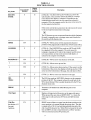
TABLE 3-1
FUNCTION OF KEYS
Key Name
RETURN!
ENTER
Transmitted?
(Yes/No)
Repeat
Action?
(Yes/No)
Y
N
Description
(CTRL/M)-The RETURN and ENTER keys perform the
same function. They send the ASCII code (OD) for a carriage
return (CR) to the display or computer. Depending on the
communication mode used, the code causes the terminal to
transmit a CR to the computer and/or the cursor to be moved to
the first unprotected position.
If the entire current line is protected, the code moves the cursor
to the next unprotected position on the page.
,1/
-0/1'
The 925 features an auto wraparound function which eliminates
the need to manually enter a carriage return and a linefeed at
the end of each 80-character line.
YIN
N
(CTRL/!\)-Moves cursor to first unprotected character
position on the page [usually Column One of Row (Line) One].
Y
Y
(CTRL/J)- The LINEFEED key sends an ASCII code (OAH)
for a linefeed (LF) to the computer. The code causes the
terminal to transmit an LF code to the computer and the cursor
to be moved down one line on the screen in half duplex, or
echoed by the computer in full duplex.
YIN
Y
(CTRL/H)-Moves cursor one character to the left.
i
YIN
Y
(CTRL/K)-Moves cursor up one line.
~
YIN
Y
(CTRL/V)-Moves cursor down one line. If the cursor is on the
bottom line of the screen, the display will roll up one line. If the
cursor is on the bottom line of the page, the code has no effect.
~
YIN
Y
(CTRL/L)-Moves cursor one character to the right.
DEL
(Delete)
Y
Y
The DEL key sends an ASCII DEL character to the computer
portion of the 925. The computer echoes the code back to the
925 to be performed. This is usually interpreted by the 925 as a
character erase code.
BREAK
Y
N
Transmits a 250-millisecond ASCII Break pulse to the
computer.
Clear Space
YIN
Y
Replaces all unprotected characters on the page with spaces.
When pressed the same time as SHIFT (ESC *), it clears the
entire page to nulls and turns off Protect and Half Intensity
modes.
Print Key
See Section 4.12
for print
functions.
YIN
N
PRINT causes all data on a page from the home position to the
cursor position to be output through the printer port. The data
is output with a CR, LF, and null automatically inserted at the
end of each 80-character line. When Print is pressed at the same
time as SHIFT, the time of day followed by a CR LF and data
will be transmitted out the (P4) printer port.
HOME
LINEFEED
BACKSPACE~
9
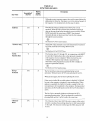
TABLE 3-1
FUNCTION OF KEYS
Repeat
Action?
(Yes/No)
Transmitted?
(Yes/No)
Key Name
Send Key
Although escape sequences appear here with a space before the
alphanumeric character, this space is not to be entered as part of
the sequence. It is included only for the sake of clarity.
I
:
N
YIN
Description
Data may be sent to a computer from the 925 by several
methods. When SEND is pressed, the terminal transmits all
data on the page from home through the cursor position. When
SEND is pressed the same time as SHIFT, the terminal
transmits all data on the present line from the first column
through the cursor position.
,I"
-0"1'
See Section 4.10 for send routines.
"FUNCT" Key
Y
N
The FUNCT key transmits a user-selected character bracketed
by CTRL/A (OlH) and Carriage Return (CR).
,I"
-0-
"1'
See Section 4.4 for FUNCT key.
I
FI-Fll
Function Keys
Y
N
I
I
The function keys, Fl through Fll, in conjunction with SHIFf
key provide 22 special keys that, when pressed, transmit a 3code sequence to your computer. When received by your
computer this sequence may initiate a special form or
subroutine in the program that causes the 925 to display or
perform a particular function.
,1/
-0/1'
See Section 4.3 for function keys.
Set-Up/
No Scroll
YIN
N
The No Scroll key stops screen updating during normal
operation. When pressed, the 925 stops updating the screen.
When pressed again, the 925 starts updating the screen.
If the receive buffer fills up while update is disabled, X-Off will
be sent to the computer, causing it to stop sending data. When
update is reenabled, the buffer will empty, causing X-On to be
sent and data to be transmitted to the computer. During normal
operation, the No-Scroll function ofthe Set-Up/No Scroll key is
active.
The Set-Up key manually displays and changes the 925's
operating characteristics. The set-up function is enabled by
pressing Shift and Set-Up/No Scroll at the same time.
Character
Insert
YIN
y
The Character Insert key (ESC Q) enters a space at the cursor
position, causing all succeeding characters to shift one position
to the right. All characters shifted past the 80th character will
be lost.
10
TABLE 3-1
FUNCTION OF KEYS
Key Name
Transmitted?
(Yes/No)
Repeat
Action?
(Yes/No)
Description
Character
Delete
YIN
Y
The Character Delete key (ESC W) deletes the character at the
cursor position and causes all succeeding characters to shift one
position to the left. All characters shifted to the cursor position
wi.ll be deleted.
Line Insert!
Delete
YIN
Y
The Line Insert (ESC E) key creates an entire line of space
characters on the cursor line. The data on the cursor line and all
following lines shift down one line (the last line on the page is
lost).
The Line Delete (ESC R) causes the entire line at the cursor
position to be deleted. All following lines shift up one line.
Line Erase &
Page Erase
YIN
N
Line Erase (ESC T) and Page Erase (ESC Y) replace the
unprotected data (from the cursor to the end of the line or page
with a space of the proper intensity.
When these keys are pressed at the same time as SHIff, they
cause a line erase to null (ESC t) or a page erase to null (ESC y).
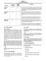
3.3.2 Other Controls
3.3.2.3 Bell
3.3.2.1 Cursor
The terminal can sound a short, loud bell upon your
command. To sound the bell, press down CTRL and G
at the same time.
The lighted rectangular block which appears on the screen
indicates the entry spot for the following characters to be
typed. It is called a "cursor." During typing, the cursor
moves from left to right. As it reaches the end of a line,
it "wraps around" to the beginning of the next line. If
you place the cursor over a character which you have
already typed, the character within the cursor will be
changed into a reverse image within the cursor. (If the
characters have been green on a black background, the
cursor will appear as a green rectangle around a black
character. )
, I .....
-0.....
,'
From now on, you will not be told to press CTRL and
the other character at the same time. The command will
be shown as CTRL/G instead.
3.3.2.4 Break
You can transmit a 250-millisecond break pulse (a break
signal) to your computer system. The effect will depend
on the operating program in your computer system. Usually it stops communication.
The movement of the cursor is easy to control. To move
the cursor, press one of the cursor control keys marked
with an arrow. The cursor will move in the direction of
the arrow until you release the key. To return the cursor
quickly to the top left position on the screen, press
HOME. The cursor will now be in Column One, Line
One.
3.4 BASIC OPERATIONS
This section describes various options available to you as
you use the terminal:
,' .....
-0-
• Setting up the terminal
..... 1'
The cursor display may appear anyone of five ways. See
Chapter 4.
• Editing data
• Tab controls
3.3.2.2 Cursor Addressing
• Emulating Tele Video 912 and 920 terminals
The Model 925 may address the cursor to any location on
the screen through a special ESC code. The cursor may
also be addressed to any page row or column the operator wants to address.
• Communicating with your computer system
• Printing
11
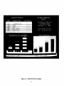
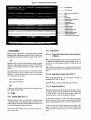
TABLE 3-2
Status Line Fields
: 920E :
• TH1E AM QQ: 13 : DUPE : •
VLO~
19.2: HDX: 9600 :
BLANK
PRINTER BAUD RATE
50,75,110,135,150,300,
600,1200,1800,2400,3600,4800,
7200,9600, 19.2K
MODE:
HDX.
FDX.
BLK.
MAIN PORT BAUD RATE
50,75,110,135,150,300,
600,1200,1800,2400,3600,4800,
7200,9600, 19.2K
- - KLOK or BLANK (KEYBOARD LOCK)
" - - - - 920 E (920 EMULATION)
- - - - - - MONT or BLANK (MONITOR MODE)
LOCE, DUPE (LOCAL EDIT) (DUPLEX EDIT)
10..-_ _ _ _ _ _ _ _ _ _ _
TIME AM or PM
HOURS: MINUTES
3.4.1 925 Status Line and Setup Mode
3.4.2 Editing
The 925 has a status line which is only displayed during
setup mode. To display the status line and enter setup
mode, press the SHIFf key and the Set-UplNo Scroll
key simultaneously. This sequence will display the status
line on the 25th line of the screen as shown in Figure 3-2.
Should you need to change text on the screen, you can
delete a line (either partially or completely) or the whole
display (either partially or completely). This will give
you space to enter the correct data. Deletions will start
with the column position under the cursor. The commands for editing are found in Chapter 4. The 925, in
addition to the above, can modify screen data using character insert/delete and line insert/delete. Both of these
take place starting at the cursor position.
You may change fields on the status line by moving the
cursor to the right using the cursor right ( -+ ) key, or to
the left using the cursor left ( ~ ) key to the field to be
changed.
3.4.3 Tab Controls
When the cursor is in the field you wish to change, press
the "T" key to toggle the field to the mode desired. Field
descriptions are shown in Table 3-2.
You can set regular typewriter-style tabs on your terminal. Pressing the TAB key causes the cursor to stop
whenever it reaches that column position, regardless of
which line the cursor was on when the tab was set. Characters can be superimposed on the tab position.
The only field that cannot be changed during setup mode
is the first field, which is the time of day.
12
Figure 3-2 Model 925 Screen Display
13
What the computer sends back to the screen (if anything)
and the action it takes on data, text, or command sequences sent to it depends on the application program in
use. Refer to the application program's user documentation for complete information.
3.4.4 Emulations
The 925 has the capability of emulating the Tele Video
912 and 920 terminals. To set the 925 to the 920 emulation mode, refer to Table 2-3, Switch Settings. All control codes for this emulation can be found in Chapter 4.
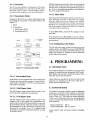
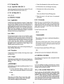
3.4.5.2 Block Mode
3.4.5 Transmission Modes
Operating in the Block Mode generally consists of entering or changing text locally. In this mode, the terminal
sends the results to the screen. When you are satisfied
with the results of the data entry or change, you can press
SEND (or use a send data control sequence) to send the
data to the computer. Block mode allows you to make all
corrections before transmission.
You may set the 925 to one of three transmission modes
by entering the setup,- pIode or setting the switches. See
'
Figure 3-3.
1. Block
2. Conversation
a. Half Duplex (HDX)
b. Full Duplex (FDX)
To enter Block Mode, enter ESC B or change it on the
status line.
If the terminal is set in Block Mode on S2 and a ESC C
is received or typed the terminal will revert to Full Duplex operation.
3.4.6 Sending Data to the Printer
The 925 will send a page of data from the screen to an
auxiliary printer when PRINT is pressed. SHIFTIPRINT
sends the time of day followed by CRLF and data to the
printer (see Chapter 4). Printing can also be controlled
by the applications program.
c:;J
4. PROGRAMMING
1_,=t-- 8
u n
4.1 INTRODUCTION
Figure 3-3 Communication Modes
Your computer program can completely control your 925
terminal by transferring the appropriate ASCII codes.
This chapter tells you how to translate keyboard functions into remote control functions.
3.4.5.1 Conversation Mode
In this mode, two-way transmission occurs continuously
between the screen and the computer. To enter Conversation mode, enter ESC C. The 925 is conversational in
either half or full duplex.
Unless otherwise specified in the text, all control code
sequences are transmitted to the 925 to elicit the response associated with the code.
3.4.5.1.1 Half Duplex Mode
4.2 MONITOR MODE
The Half Duplex mode sends keyboard entries to the
screen and to the computer at the same time.
The Model 925 provides a Monitor mode for displaying
all characters received from the computer or entered on
the keyboard, including escape and control sequences
(refer to Table 4-1). The escape and control sequences
on the screen will provide visual cues in long program
routines. To control the Monitor mode, use the following
code sequences:
3.4.5.1.2 Full Duplex Mode
The Full Duplex mode sends keyboard entries to the
computer only. If the computer is programmed to act
upon a code received from a keyboard entry, it may echo
the result back to the 925. (The time needed to echo back
the information is so short it will seem to happen simultaneously!) For example, if the "A" is pressed on the
keyboard, the computer will probably send the "A" back
to the 925's screen.
Monitor Mode ON ESC U
Monitor Mode OFF ESC u or ESC X
Using monitor mode will make program debugging
easier.
14
TABLE 4-1 MONITOR MODE
CODE
ASCII
HEX
A@
AA
AB
}C
AD
I.E
AF
AG
AH
AI
AJ
AK
AL
AM
AN
NULL
SOH
STX
ETX
EDT
ENQ
ACK
BEL
BS
HT
LF
VT
FF
CR
SO
00
01
02
03
04
05
1.0
51
Ap
AQ
AR
AS
DLE
DCI
DC2
DC3
DC4
NAK
SYN
ETB
CAN
EM
SUB
ESC
FS
GS
RS
US
DEL
AT
AU
AV
AW
AX
AY
AZ
ESC
A\
A]
AI.
A
DEL
SCREEN
CHARACTER
none
SH
Sx
EX
ET
EQ
AK
BL
BS
HT
LF
VT
FF
CR
So
SI
DL
DI
D2
D3
D4
N K
SY
EB
CN
EM
5 B
EC
FS
GS
RS
Us
06
07
08
09
OA
OB
OC
OD
OE
OF
10
II
12
13
14
15
16
17
18
19
IA
IB
IC
ID
IE
IF
7F
'.'
<.-:
4.3 FUNCTION KEYS
4.4 FUNCT (FUNCTION) KEY
The Model 925 has the ability to transmit special function codes to your computer. This is possible through the
eleven function keys located on the keyboard (Figure
3-1).
Operation of these keys (F1 through Fll) causes the following three-code sequence to be transmitted. When the
shift key is used in addition to the function keys, the
following three code sequence is transmitted.
-
Not to be confused with the Function keys (4.3), the
FUNCT key transmits a user-selected character bracketed by Control A (SOH) and a Carriage Return (CR).
For example, if a Control A C CR sequence is required
for a special operation in a text editing program, pressing
FUNCT and C at the same time transmits CONTROL A
C CR to the compute. automatically.
Key
F1
F2
F3
F4
F5
F6
F7
F8
F9
FlO
Fll
<I
Unshifted
Code
CTRL/A
CTRL/A
CTRL/A
CTRL/A
CTRL/A
CTRL/A
CTRL/A
CTRL/A
CTRL/A
CTRL/A
CTRL/A
11111
@ CR
A CR
B CR
C CR
o CR
E CR
F CR
G CR
H CR
I CR
J CR
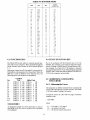
4.5 ADDRESSING AND READING
THE CURSOR
Shifted Code
CTRL/A ' CR
CTRL/A a CR
CTRL/A b CR
CTRL/A c CR
CTRL/A d CR
CTRL/A e CR
CTRL/A f CR
CTRL/A g CR
CTRL/A h CR
CTRL/A
CR
CTRL/A
CR
4.5.1 Addressing the Cursor
The computer can tell the terminal where to position the
cursor with a four-character escape sequence. (See Table
4-2) This is called "loading" the cursor.
To load the cursor on a 925 with two pages of memory
installed, enter
ESC-PRC
where
I
P = 0 for page 1; 1 for page 2
R = the desired row (line)
C = the desired column (character)
To change the default value of the function keys, the system ROM of the 925 must be replaced with a modified
2732 EPROM.
15
Use Table 4-2 to find the ASCII code representing the
desired row and column. Find the appropriate ASCII
code corresponding to the desired column position (1
through 80 possible) and enter that code.
To load the cursor with one page of memory (standard),
enter
ESC= rc
where r = desired row/line
c = desired character
For example, if you want to program the cursor to go to
Row 9, column 50, enter
ESC
4.6 VIDEO ATTRIBUTES
The 925 screen attributes (see Figure 4-2) may be controlled to provide reverse video, half intensity, underline, blink, and blank. The attribute characters are
normally displayed as a space on the screen. They also
appear as a half-intensity space on a black-on-green
background. The attributes are implemented with an ESC
G sequence followed by a parameter. For the video attributes, enter the following codes in the exact sequence
shown below:
= (0
<I
ESC
ESC
ESC
ESC
ESC
ESC
ESC
ESC
ESC
ESC
ESC
ESC
ESC
Normal (green on black) video
Blank
Blink
Invisible blink
Reverse (black on green)
Invisible reverse
Reverse blink
Invisible reverse blink
Underline
Invisible underline
Underline blink
Invisible underline blank
Underline reverse
Invisible underline reverse
Underline reverse blink
Invisible underline reverse blink
Half Intensity On
Half Intensity Off
ill I
If your computer inserts nulls between characters, loading the cursor will not function as described; instead the
cursor will go to an unpredictable position.
4.5.2 Reading the Cursor
The computer can also "read" the cursor's page, row,
and column position. To read the cursor's position, enter
ESC?
To read the cursor position with more than one page of
memory installed, enter
ESC!
This causes the computer to read the cursor's current
page (if additional page is installed), row, and column
position. Rowand column are read as specified in the
cursor addressing table, followed bya carriage return.
ESC G=
ESC G>
ESC G?
ESC)
ESC (
TABLE 4-2 MODEL 925 CURSOR ADDRESSING CODES
POsmON
RorC·
AScnCODE
'Ii'ansmiUed
1
Space
2
!
3
4
5
6
7
8
9
10
#
$
%
&
13
14
15
16
17
18
19
20
21
AScnCODE
1hmsmitted
POSmON
C
33
34
35
36
37
38
39
@
65
A
66
a
B
67
C
D
68
b
c
d
41
42
43
+
44
45
L
M
N
0
46
47
I
48
49
50
51
52
53
24
0
1
2
3
4
5
6
7
25
8
26
9
57
58
59
22
23
F
G
H
I
J
K
40
11
12
27
ASCnCODE
POsmON
C
E
28
29
30
;
60
<
31
32
>
61
62
63
?
64
71
72
g
73
74
75
76
77
78
79
h
j
k
I
m
n
0
81
P
q
R
83
r
S
T
84
s
85
86
87
88
t
u
82
89
v
w
Z
[
91
92
x
y
z
{
\
93
I
J
94
}
y
/\
90
95
96
16
e
f
P
Q
V
W
X
·Value of R can't be greater than 24.
'IhmsmiUed
80
U
54
55
56
69
70
G9
Gl
G2
G3
G4
G5
G6
G7
G8
G9
G:
G;
G<
I
DEURUB
Figure 4-2 Model 925 Video Attributes
- - - - Half Intensity Off
_ - - - Half Intensity On
- - - - Normal (green on black) video
----Blank
----Blink
- - - - Invisible blink
- - - - Reverse (black on green) video
~---Invisible reverse
,....-----Reverse blink
----Invisible reverse blink
- - - - Underline
----Invisible underline
- - - - Underline blink
----Invisible underline blank
----Underline reverse
- - - - Invisible underline reverse
- - - - Underline reverse blink
- - - - Invisible underline reverse blink
<I
4.7.2 Using Tabs
ill d I
When used in combination with Protect mode, all half
intensity fields will denote a protected field. Half intensity fields do not take up a character space on the screen.
4.7.2.1 lYpewrite Tab (Protect and Unprotect)
(CTRL/I)
When the Protect mode is off, the code causes the cursor
to advance through the next typewriter-style tab set. If
no tabs are set, the code has no effect and the cursor will
not move.
When the Protect mode is set, the cursor is moved to the
first unprotected character following the next protected
field.
::6~
",'
When the 925 is in the 912/920 emulation mode, all video
attributes will respond to those used by the 912/920 terminal; see 925 Quick Reference Guide (inside back
cover).
The entire screen of the 925 may be reversed from a black
on green screen to a green on black screen, or from green
on black to a black on green with a one-code sequence.
To reverse the screen, enter
4.7.2.2 Field Tab (Protect only) (ESC i)
With the Protect mode set, the cursor moves exactly as
described for CTRL/I, above.
ESC b (black on green)
ESC d (green on black)
With the Protect mode off, this code has no effect.
,'"
-0-
4.7.2.3 Back Tab (ESC I)
"I'
Using one of the above codes does not take up a character space on the screen.
When the Protect mode is off, the code causes the cursor
to back to the previous tab position set. If no tabs are set
or if the cursor is on the first tab position, Back Tab
moves the cursor to the first column on the line.
4.7 TABS
4.7.1 Setting Tabs (ESC 1)
If the Protect mode is on, Back Tab moves the cursor
back to the start of the first preceding unprotected field.
If no preceding positions exist, the cursor will not move.
When the Protect mode is on, the ESC 1 code generates
a vertical column of half intensity spaces from the cursor
position down to the first write-protected character or to
the end of the page, whichever is first.
If the cursor is at the first unprotected position on the
page, the code has no effect. If no protected fields exist,
Home position is considered the start of an unprotected
field.
When the Protect mode is off, the code sets a typewriterstyle column tab.
17
4.7.3 Clearing Tabs
c. Enter the information for that area of the screen.
4.7.3.1 Typewriter Tabs (ESC 2)
d. Proofread the entry and change if necessary.
Clears the typewriter tab at the cursor column. The code
has no effect when the Protect mode is set.
e. End data entry in that area by entering
ESC (
4.7.3.2 All Tabs (ESC 3)
This turns off the Protected Writing mode
Clears all tabs.
f. Move the cursor to the next area to be protected
and repeat.
4.8 PROTECT MODE
4.8.1 Application
4.8.3.2 Protection
Using Protect mode during the creation of a page allows
you to protect designated areas of the page from future
change by the operator and control its transmission. A
typical application would be the creation of a form, leaving blank spaces for later entry of variable information.
Where the form headings not protected by Protect
mode, they would be vulnerable to change or accidental
deletion as the form was being filled in.
When all areas to be protected have been entered correctly, the whole screen is ready to be protected from
change (Protect ON). Once this protection is given, the
cursor will not be able to enter those areas unless the
protection is removed.
To start Protect mode, enter
ESC&
4.8.2 Effect
<I
Protected areas appear on the screen at half the regular
intensity. The cursor is not able to enter a field which has
been protected, but will instead advance across that area
to the first unprotected field when entering arrow right
or left. Arrow up, down, linefeed, or reverse linefeed
may, however, move the cursor to the protected field. If
the whole screen is protected the cursor will go to the
HOME position and will not move.
The position of the cursor is irrelevant during this escape sequence.
This turns on the Protect mode. Protect mode causes
half-intensity and attribute characters to be protected from
overwriting or erasure. All visual attributes within protected areas are protected.
Protect mode affects cursor action during tabulating, editing, sending, and printing.
To remove Protect mode (Protect OFF), enter
ESC'
4.8.3 Procedure
All characters entered are displayed at full intensity.
Using Protect mode is actually a two step process: input
and protection.
4.9 EDITING CONTROL
4.8.3.1 Input
The editing control sequences and a description of their
functions follow:
Individual areas (fields) which will be given blanket protection from later change are created using Protected
Writing.
<:1
111111
8
111111
Use of the Model 925 editing commands may result in
the loss of data. Read the following explanations of the
editing control functions carefully.
Information must be input using this procedure if it is to
be protected later.
a. To start Protected Writing, position the cursor
where the first protected character is to be located.
4.9.1.1 Set Local Edit Mode (ESC k)
Sets the edit keys (CHAR INSERT, CHAR DELETE,
LINE ERASE, PAGE ERASE, SEND, PRINT, LINE
INSERT, LINE DELETE, CLEAR, BACKSPACE, t,
t, ~,~, TAB, and BACK TAB) for local operation
only. These keys will affect data in the terminal; no characters associated with the keys will be transmitted to the
host. All other keys operate normally.
b. Enter
ESC)
This turns on the Write Protect mode (also called
Half Intensity). Until the mode is reset, each character entered is displayed at half intensity.
18
• Carriage return (CTRLIM)-Moves the cursor left
to column 1 of the current line.
4.9.1.2 Set Duplex Edit Mode (ESCl)
Sets the edit keys (see above) to operate in the mode set
for the alphanumeric keys. For example, if the terminal
is set for Half-Duplex operation (refer to paragraph
3.4.5.1.1), the alphanumeric keys operate in Half Duplex mode, and the edit keys operate in Half Duplex
mode.
• Cursor Home (CTRL/I\ )-Moves the cursor to the
first unprotected character on the page.
• New line (CTRL/_)-Causes the terminal to perform a carriage return and a line feed .
4.9.2 Cursor Control
The cursor control key operation is described in paragraph 3.3.3. Escape and Control sequences may be sent
from the host to perform the various cursor functions.
4.9.2.2 Normal and Reverse Linefeed
The linefeed control code sequences and a description
of their functions follow:
4.9.2.1 Cursor Control Codes
8
The cursor control code sequences and a description of
the functions follows:
Linefeeds received by the Model 925 under certain
conditions may result in the loss of data. Read the following control code explanations carefully!
• Cursor up (CTRL/K)-Moves the cursor up one line
until it encounters the top of the screen. If the cursor
is not on the first line of the page, the display will roll
down one line each time until the cursor reaches the
top of the page. Once it reaches the top of the page,
further receipt of the code has no effect.
• Linefeed (CTRL/J or LINEFEED)-With Auto Page
and the Protect mode off, a linefeed advances the
cursor to the next line on the page. If the cursor is at
the bottom of the screen, linefeeds cause the display
to roll up one line for each linefeed. If the cursor is
also at the bottom of the page, a linefeed causes a
new line of data to appear at the bottom of the screen
and results in the loss of the top line of data on the
page. The new line contains spaces. Shifted t causes
a linefeed.
• Cursor down (CTRLN)-Moves the cursor down
one line. If the cursor is on the bottom line of the
screen, the display will roll up one line. If the cursor
is on the bottom line of the page, the code has no
effect.
• Cursor left (CfRL/H)-Same as BACKSPACE.
Moves the cursor left to the next unprotected position on the page. If the cursor is currently in the first
column of the line, it will move to the last column of
the preceding line or to that line. If Auto Page is off
and the cursor is currently at the Home position or
the first unprotected position on the page, the code
has no effect.
With the Protect mode off or on and Auto Page on,
linefeed advances the cursor to the next line on the
page. When it reaches the bottom of the page, it
advances to the first line of the next page. When it
reaches the last line of the last page, it advances to
the first line of page O.
With the Protect mode on and Auto Page off, the
cursor advances to the top of the current page when
it reaches the bottom of the page.
• If Auto Page is on and the cursor is at the Home
position or the first unprotected position on the
page, the cursor will move to the end of the preceding page or to the last position of the last unprotected
field of the preceding page. If the current page is
page 0, the code has no effect.
• Reverse linefeed (ESC j)-Moves the cursor up one
line for each reverse linefeed received. If the Protect
mode is on and Auto Page is off, the cursor stops
when it reaches the top line of the page. If Auto Page
is on and the Protect mode is on or off, the cursor
moves to the last line of the previous page when it
reaches the first line of the current page. If the cursor
is at line 1 of page 0, it will not move.
• Cursor right (CTRLIL)-Moves the cursor right one
column; if at column 80, it moves the cursor to the
first column of the next line. With Auto Page off and
the Protect mode off, it will cause a scroll if the cursor is at column 80 of the last line. With Auto Page
on and the cursor at the last unprotected position on
the page, the cursor will advance to the first unprotected position of the next page. If the page is the
last, the cursor will advance to Home of the first
page. With Auto Page off, the Protect mode on, and
the cursor at the last unprotected position on the
page, the cursor will move to the first unprotected
position of the current page.
If the Protect mode and Auto Page are off, the screen
will scroll down one line when the cursor reaches the
top line of the screen. If the cursor is also at the top
of the page, the page will scroll down one line, causing a new line of data to appear at line 1 of the screen
and deleting the last line of the current page. Shift i
causes a reverse linefeed.
19
4.9.2.3 Editing Commands
• Clear unprotected to nulls (ESC :)-Clears all unprotected data on the page to the null character (or
half-intensity nulls if set).
• Clear unprotected to insert character (ESC ; or
ESC + or CTRL/Z)-Clears all unprotected data
on the page to the insert character. The insert character is a space by default. If Half Intensity (H.I.) is
set, the screen will be cleared to half-intensity insert
characters.
• Character Insert (ESC Q)-Causes the character at
the cursor to move right one column and enters a
space character at the cursor position. The character
at column 80 is lost. If the Protect mode is on, this
control will insert from the cursor position to the end
of the line or to the first protected field.
• Character Delete (ESC W)-Deletes the character
at the cursor position and moves all following characters left one position. At the end of the delete
function, a space character is written into the last
position on theJine. If Protect mode is on, character
delete operates only from the cursor position to the
end of the unprotected field or line.
• Clear page to half-intensity spaces (ESC,)-Clears
all unprotected data on the page to half-intensity
spaces.
• Clear all data to nulls (ESC *)-Clears all data on
the page to nulls and resets the Half Intensity and
Protect modes.
• Line Insert (ESC E)-With the Protect mode off,
inserts a line consisting of fill characters at the cursor
position. This causes the cursor to move to the start
of the new line and all following lines to move down
one line, resulting in the loss of the last line on the
page. If the Protect mode is on, a line insert command has no effect.
4.10 SEND FUNCTION
Once d.ata or text has been entered and edited, it may be
the computer by either pressing SEND or
by entenng a control sequence to send specific data. To
send the computer specific data, type the code in the
exact sequence shown in the following send descriptions.
transmlt~ed to
• Line Delete (ESC R)-When Protect mode is off,
deletes the line at the cursor position, and all following lines move up one line. Also causes the cursor to
move to column 1 of the line and fill characters to
load into the last line of the page. Has no effect when
Protect mode is on.
4.10.1 Send Line Unprotected (ESC 4)
Sends all unprotected data on a line from column 1
through the cursor position. The code also sends field
delimiters in place of protected fields and an end-of-text
character at the end of the send transmission.
• Erase to End of Line (ESC T)-Erases all unprotected characters from the cursor to the end of the
line (or field, if in the Protect mode) and replaces
them with fill characters. If Half Intensity is on, fill
characters in half intensity will replace the erased
characters.
4.10.2 Send Page Unprotected (ESC 5)
Sends all the unprotected data on page from Home
through the cursor position. It sends field delimiters in
place of protected fields. The code also sends a line delimiter at the end of a line and an end-of-text character
at the end of the send transmission.
• Erase to End of Line with Nulls (ESC t)-Erases all
characters from the cursor position to the end of the
line or the end of an unprotected field and replaces
them with null characters. If Half Intensity is on, the
erased characters are replaced with half-intensity
null characters.
4.10.3 Send Line All (ESC 6)
• Erase to End of Page (ESC Y)-Replaces unprotected characters from the cursor position to the end
of the page with spaces. If Half Intensity is on,
erased characters will be replaced with half-intensity
spaces.
Sends all data from the first column through the cursor
position. It also sends the start-protected field and endprotected field delimiters at the start and end, respectively, of each protected field. If the character at the cursor position is protected, the 925 sends an end-protected
field to the computer. The code sends the end-of-text
character at the end of the send transmission.
• Erase to End of Page with Nulls (ESC y)-Erases
all unprotected characters from the cursor position
to the end of the page and replaces them with null
characters. If Half Intensity is on, erased characters
are replaced with half-intensity null characters.
,I . .
-0-
....,'
4.9.2.4 Clear Function
If the data to be sent includes attribute characters, these
will be sent too (the 925 will automatically include the
suitable escape sequences).
The Model 925 clear function is used in one of four ways
to clear data from screen memory and/or computer
memory. The clear function escape codes and a description of their functions follow:
This also applies to any attribute characters encountered
on the screen.
20
two-way communications between a KSR-type printer
and the computer. If during a print operation, the device
connected to the printer port cannot accept any more
data, the device may signal the terminal to stop sending
data by setting P4-20 to -12 Vdc. The device may then
request the transmission of more data by setting P4 20 to
+ 12 Vdc. Refer to 2.4.7 for field modifications which
affect the printer port.
4.10.4 Send Page All (ESC 7)
Sends all data on the page from Home through the cursor
position. It also sends the start-protected field delimiters
at the start and end, respectively, of each protected field.
If the character at the cursor position is protected, the
925 sends an end-protected field delimiter to the computer. This code also sends the end-of-text character at
the end of the send transmission.
The print function control sequences and their descriptions follow.
4.10.5 Send Message Unprotected (ESC S)
4.12.1 Page print (ESC P)
Sends all unprotected data bracketed by the state of text
(STX) and end of text (ETX) codes displayed on a page.
After the data is sent, the 925 positions the cursor at the
ETX code. If the page contains no STX codes, transmission begins from Home. If the page contains no ETX
code, the 925 sends to the end of the page and positions
the cursor at Home after the data is sent. If the page
contains neither an STX nor an ETX code, the entire
page will be sent. The code sends field delimiters in place
of protected fields. It also sends line delimiters at the end
of each line and an end-of-text delimiter at the end of the
send transmission.
Sends page data from Home through cursor position to
the printer port and advances the page number by 1.
Data entry on the advanced page may continue while the
previous page is printing. This print mode prints page
data exactly as entered plus line delimiters (a carriage
return and a linefeed) at the end of each line. Control
characters are also sent to the printer port as are a carriage return and a linefeed at the end of the transmitted
data. The terminal transmit an ACK to the host indicating that all print data has been output to the printer port.
4.12.2 Transparent print on (ESC" )
4.10.6 Send Message All (ESC s)
Operates in the same manner as ESC S, except that protected fields delimited by start-protected field and endprotected field are also transmitted.
Sends all subsequent data received by the terminal (including control and escape characters) to output to the
printer port. No screen updating occurs while the mode
is active. The printer and main baud rates must be the
same.
4.11 TERMINATION CHARACTER
SELECTION
4.12.2.1 Transparent print otT (ESC a)
Turns off the transparent print. The printer and main
baud rates must be the same.
At the completion of each send sequence, a Carriage
Return (CR) is sent to the computer. This termination
character may be changed to any ASCII code. To change
the termination character, enter
4.12.3 Extension (copy print) mode on (ESC @)
ESCx4NN
Causes all subsequent data received by the terminal to
be sent to the screen and to the device connected to the
printer port. The printer and main baud rates must be
the same.
where NN = any two ASCI! characters
Example: To change the termination character to a ETX
enter
CTRL/@(NULL)
4.12.4 Extension (copy print) mode off (ESC A)
CfRL/C (ETX)
Turns off the Extension (copy print) mode. Screen updating continues normally.
For NN, two characters must be entered. Use a NULL
(CTRUA) as a filter code.
4.12.5 Enable bidirectional port (CTRLIR)
• Line Terminator-at the end of each line a US (1FH)
is transmitted. To change the line termination character, enter
Functionally connects P3 RS232C and P4 PRINTER in
parallel. The function allows a device connected to the
printer port [such as a keyboard send/receive (KSR)
printer] to communicate directly with the computer
while allowing screen update to continue.
ESCx1NN
where NN = any two ASCII characters.
4.12.5.1 Disable Bidirectional Port (CTRL/T)
4.12 PRINT FUNCTION PROGRAMMING
Functionally disconnects P3 RS232C and P4 PRINTER
in parallel.
The Model 925 printer port may be set for terminal page
date transmittal, data transmittal from the computer or
21
4.12.6 Send Time of Day
To change the time, enter
ESC SPACE 1 N HH MM
The 925 has a built in clock which keeps track of the time
of day. To transmit the time to your printer, press the
PRINT key in conjunction with the SHIFT key. The time
will then be transmitted to the printer followed by a CR!
LFanddata.
where N
HH
MM
A( AM) or P(PM)
2 digit number for the hour
2 digit number for the minutes
4.12.7 Printer Termination Character
Example:
The printer's termination character may be reprogrammed to any character desired. To program the termination character, use the following dialogue.
If you wish to program 3 o'clock in the afternoon, enter
ESC SPACE (SPACE BAR 20H) 1P 0300
ESCpn
<::::~I~~~IIlIJII[1JI
Example: To program a null for the termination character, type:
The time of day may be sent to the printer for reports;
see Section 4.12.6, print functions.
ESCpCTRL/@
The computer may request the time from the 925 by
sending the following sequence:
The default printer termination character is an ACK
(CTRLIF).
ESC SPACE 2
4.13 X-ON/X-OFF CONTROL
The 925 will respond with a 6-character code (A or P,
hour and minutes and CR).
The Model 925 automatically transmits X-OFF to the
computer, requesting it to stop sending data when the
terminal's receive buffer is almost full (less than 16 characters). When the data in the buffers are processed (output to the screen or to the printer buffer), the Model 925
automatically transmits X-ON to the computer, indicating that the computer may resume sending data to the
terminal. The X-ON/X-OFF feature may be enabled or
disabled with the following control sequences:
Enable X-ON/X-OFF
and disable DTR Control
CTRLO
Disable X-ON/X-OFF
and enable DTR Control
CTRLN
4.16 KEYBOARD KEYCLICK
The Model 925 features an audible keyclick whenever a
key on the keyboard is depressed. The keyclick may be
disabled either through a switch (see Table 2-4) or software control.
Keyclick ON ESC>
Keyclick OFF ESC <
4.17 DISABLING THE KEYBOARD
4.14 DTR CONTROL
You can disable all keyboard functions by remote commands from the computer. Once the keyboard is disabled, it can only be enabled once again by another
remote command from the computer.
The Model 925 Data Terminal Ready (DTR) line will go
low whenever the 256-byte storage receive buffer fills to
240 bytes. The DTR line will go high again once the
buffer is 20 per cent empty. The DTR feature may be
enabled or disabled by changing the following switch
setting:
8
If your computer system echoes all codes, the keyboard
may be accidentally disabled.
S3 switch 10
UP
DTR Disconnected
DOWN DTR Connected
See 2.4.7 for field modifications which control DTR output.
To disable the keyboard remotely, enter
ESC #
4.15 TIME OF DAY CLOCK
While the keyboard is disabled, all keys are disabled except FUNCT, PRINT, BREAK.
The 925 has a time of day clock. The time of day will
appear only when the status line is displayed during SetUp mode. It will appear in the first field of the Status
Line as follows:
TIME A(AM) P(PM)
To subsequently enable it, you must receive an ESC
from the computer or type a SHIFT/BREAK BREAK
(reset) from the keyboard.
1/
XX(HOUR):XX(MINUTES)
22
4.18 SCREEN TIME OUT
4.20.2 Entering Data
The 925 has a time out device used to increase the life of
the phosphor on your screen. If this feature is selected
(see Table 2-4), the data displayed on the screen will
turn off 15 minutes after the last keystroke entered. The
925 is normally shipped with this feature disabled. To
display the screen after it has shut off, press any key.
You can enter up to 79 characters of text on the User
Line. Press RETURN to terminate entry of the user
message.
<I
illlll
The User Line will be cleared when power is turned off
or an ESC h is received.
4.21 912C/920C EMULATION
No data will be lost as long as the terminal has not
been turned off.
The model 925 offers a firmware emulation of the
TeleVideo Models 912C and 920C.
,I",
4.19 PAGE CONTROL
The Model 925 has the option of two 24-line pages of
display memory. These pages may be incremented forward or backward, one page at a time. When the next
page or previous page is called to the screen, the cursor
assumes the last position previously occupied on that
page. To control the paging functions, enter the following codes in the exact sequence shown below.
Do not enter the spaces between the characters;
spaces are for clarity only.
Advance page
ESC K (advances to next page)
Back page
ESC J (displays previous page)
ESC P (sends current page data
Print page and
to the printer and displays
display next page
the second page)
Auto flip on
Auto flip off
ESC v (When the cursor is
advanced past the 24th
line, 80th character, the
925 will flip to the next
page)
ESC w (When the cursor is
advanced past the 24th line,
80th character, the cursor
will move to the HOME
position. )
4.20 USER LINE
4.20.1 To load the User Line
Enter,
ESCf ... CR
where ... = data to appear in the user line up of 79
characters.
To cause your entry to be displayed, enter
ESCg
(You can enter data and display it later or you may display the blank User Line before entering data. This allows you to see the data as it is loaded.)
The cursor will not enter the User Line while you are
23
inputting data.
-0-
"'I'
You can put the 925 in the 912/920 emulation mode
by entering the set-up mode or putting S1 dipswitch two in the down position.
The differences in codes between the 925 and 912/920
are shown in the Operator's Quick Reference Guide.
4.22 Cursor Attributes
The cursor display may appear anyone of five ways. To
set the cursor display, enter the control code for the desired attribute. Type the code in the exact sequence
shown below (do not enter the spaces between the characters; spaces are for clarity only):
4.23 Screen Off
Attribute
Not Displayed
Blinking Block
Steady Block
Blinking Underline
Steady Underline
Code
ESC.O
ESC.1
ESC.2
ESC.3
ESC.4
To blank the entire screen, enter
ESCO
To return the screen to normal display, enter
ESCN
5. PREVENTIVE
MAINTENANCE
5.1 CARE
Tender loving care will prolong the useful life of your
terminal. Clean and inspect it periodically.
5.1.1 Cleaning
To clean the terminal exterior:
1. Vacuum the keyboard every three months with a
soft brush attachment (or use a small soft brush).
2. Clean the housing with a soft, lint-free cloth and a
commercial detergent every three months.
DO NOT use solvent-based or abrasive cleaners.
6.2 REPAIR
5.1.2 Inspection
Description
1. Inspect the terminal cabinet for
cracks or breaks.
Frequency
IfYr.
Model 925 operator repair is limited to changing the line
fuse and the two internal power supply fuses.
6,,2~ 1
2. Check each key for free movement.
IfYr.
3. Check the cable connector (at the
rear of the terminal cabinet) for
damage.
IfYr.
Changing the Line Fuse
To change the line fuse, proceed as follows:
8
To avoid electrical shock, disconnect the terminal power
cord before changing the line fuse.
1. Disconnect the terminal power cord from primary
power.
2. Remove the fuse holder (see Figure 2-2) by unscrewing it counterclockwise.
6. TROUBLESHOOTING AND REPAIR
3. Remove the blown fuse and replace it with a 3AG,
1 amp "slo blo" 125V or 0.5 amp, 250V fuse for 220
VAC applications instantaneous (fast blow) fuse.
4. Install the fuse in the reverse order of Steps 1
through 3.
6.1 TROUBLESHOOTING
Your computer terminal is just one of several components in the computer system. A failure anywhere else in
the system can cause the improper operation of the terminal. The computer system, memory systems, cables,
modems, and operational procedures should be checked
if there has been a malfunction. Table 6-1 will be helpful
in determining the cause of a problem. If this table does
not help locate the cause of the problem, run the self test
or call a qualified service technician for assistance.
6.2.2 Changing the Power Supply Fuses
The terminal power supply fuses are installed in fuse
clips on the power supply assembly inside the terminal
(see Figure 2-3). To replace either of these fuses, proceed as follows:
8
Hazardous voltages are exposed in the cabinet. Turn off
the power switch and disconnect power before opening
the terminal cabinet.
6.1.1 Testing the Terminal (Self Test )
You can test the terminal yourself to verify proper operation of the video display circuitry. The test will display
all displayable characters, and all 16 video attributes-in
both half and full duplex.
1. Disconnect the terminal power cord from primary
power.
To start the test, enter
2. Turn the terminal upside down and set it on a soft
surface to prevent marring the cabinet. Remove
the four Phillips screws that hold the cabinet cover
on the terminal.
SHIFf/Setup 1
The display screen should now look like that in Figure
4-2. Look at the display carefully to verify that all characters appear, all video attributes appear correctly, and
all half intensity characters are shown. Each character
should be formed properly and you should not be able to
see any extra dots (and no dots should be missing).
3. Turn the terminal right side up and lift off the cabinet cover.
Make sure there is adequate table space for the open
terminal.
Check the switch settings on the terminal against those
on the display (see Fig. 4-2). The display will show the
dip switches as a 1 (up) or a 0 (down).
4. Remove the blown fuse from its fuse clip (see Figure 2-3).
To stop the test
5. Replace the blown fuse with a 3AG, 3 amp, 125V
fuse.
press SHIFfIBREAKlBREAK
6. Reinstall the terminal cover and secure it with the
four screws. (Do not overtighten screws!)
Should your display not appear as pictured in Figure 4-2
call a qualified service technician.
24
TABLE 6-1
TROUBLESHOOTING TERMINAL PROBLEMS
Symptom
Possible Cause
Solution
Terminal dead (no beep; no cursor)
No ACpower
Plug in power cord.
Turn on power switch.
Check 115/230 power switch setting.
Terminal dead; cursor may appear
Loose or defective line or power
supply fuses
Turn terminal power off and change
fuses.
Terminal will not go on line
System is not "up"
Check status of system.
Loose, unconnected, or damaged
cables
Attach all cables and check for
cable damage.
Check main port (P3) interface
cable pins:
• 5,6, and 8 must be driven by + 12
VDC or not connected at all for
normal operation. See Table 2-4.
• 1 and 7 must be grounded.
• 3 must be connected to the host
transmitter.
• 2 must be connected to the host
receiver.
Modem not turned on, defective, or
phone handset on modem upside
down
Turn on modem.
Attach different modem.
Check phone handset position.
Cursor will not appear
Defective contrast pot
Contrast set too light
Refer to technical representative
for adjustment of contrast settings.
System does not respond while on
line
Incorrect parity switch setting, word
structure, stop bits
Set parity switch to match system.
Terminal is not responding to
settings
Terminal not powered down after
being reconfigured; software has not
scanned new settings.
Power down terminal and turn back
on.
Terminal "locked up"
System is not responding;
communication link broken
Set to half duplex and try to type. If
terminal will type, check cables,
modem, phone lines, and computer
system. Set to full duplex and
perform self test.
Terminal incorrectly set for on line
and full duplex
Set to half duplex.
Keyboard disabled from computer
Enter ESC"
Switches set incorrectly
Review Chapter 2 switch settings
carefully and check all switch
settings.
Terminal locked up
25
TABLE 6-1 Continued
TROUBLESHOOTING TERMINAL PROBLEMS
Symptom
Possible Cause
Solution
Terminal prints correct data only
part of the time
Parity settings incorrect
Check parity settings with system
requirements.
Stop bits or word structure wrong
Change switch settings.
Display is wavy
Hertz setting incorrect; does not
match local power frequency
Change switch setting.
Printer does not print what is
transmitted
Correct print mode selected?
Refer to 4.12.1 and 4.12.2.
Cable connector pins connected
incorrectly
Refer to Table 2-2.
Check printer port (P4) interface
cable connector pins:
• 4 or 20 must be driven by + 12
VDC or not connected at all for
normal operation.
• 3 must be connected to printer
data input.
Check other printer port device
requirements.
Escape and control codes do not
function as specified
The escape and/or control codes
being used are not correct
Check model number of terminal
and code table for correct model of
terminal being used.
Make sure upper and lower case
codes are used. Is a numeral one
required instead of lowercase "L"?
Terminal prints "garbage"
Keyboard locked in SHIFT position
(AUTO LOCK on)
Put in lower case. Disconnect
computer system. Connect P3-2 to
P3-3 and try in full duplex.
Improper baud rate setting
Set correct baud rate.
Improper handshaking protocol
Check handshaking protocol
requirements of system with
terminal protocol.
Defective modem
Replace modem
Noisy telephone lines
Check phone lines.
Install dedicated phone lines.
Static electricity
Check operating environment for
static.
EIA and AC power cords
intermingled
Separate cables. Keep EIA cable
separate from power cord to
prevent noise on data line.
26
TABLE 6-1 Continued
TROUBLESHOOTING TERMINAL PROBLEMS
Symptom
Possible Cause
Solution
Terminal prints "garbage"
AC outlet not wired properly
Check for proper wiring and
grounding.
Erroneous data sent to computer
Scrambled output
Terminal loses memory
Static electricity
1. Check operating environment
for static problems.
2. Install antistatic floor mat.
3. Spray carpeting with antistatic
spray.
4. Increase humidity.
AC outlet not wired properly
Check for proper wiring and
grounding.
Terminal does not print what is
typed while on line
Duplex switch incorrectly set
Set duplex switch to match host
system.
Terminal only prints @ characters
Word length switch set incorrectly
Set word length switch to match
computer system.
Parity switch set incorrectly
Set parity switch to match computer
system.
Stop bits set incorrectly
Set stop bit switch to match
computer system.
GLOSSARY
ASCII
BREAK
The acronym for American Standard Code for Information Interchange. This is a standardized code for the
transmission of data within the United States. It is composed of 128 characters (upper and lowercase letters,
numerals, punctuation marks, symbols, and control
characters) in a 7-bit binary format.
To break or interrupt communications. When the
BREAK switch on the terminal is toggled, a 250-millisecond tone is sent to the computer to immediately halt
communications.
Buffer
Asynchronous Communication
An electronic device within the terminal that allows for
the temporary storage of incoming data should the transmission rate of the incoming data be faster than the terminal's printing speed.
A method of communication where the time synchronization of the transmission of data between the sending
and receiving stations is set by start and stop bits and the
baud rate.
Bug
Baud
An error in a computer program or in the operation of
the computer.
The rate of transmission of data. One baud equals one
binary bit per second.
Bit
Byte
An abbreviation for binary digit. A bit is the smallest
unit of data. ASCII codes are composed of seven bits.
A coded group of binary bits which represents a character (letter, numeral, symbol, command, etc.).
27
Code
Half Duplex
A method of representing data by groups of binary
digits.
In half duplex communication, the terminal transmits
and receives data in separate, consecutive operations.
Transmitted data is printed locally.
Command
Handshaking
A code that will cause the terminal or computer to perform an electronic or mechanical action.
An electronic system which, in accordance with its programming, will store the process information and perform high-speed mathematical or logical operations.
A communications protocol which is necessarily used
when the transmitting speed of the computer is faster
than the printing speed of the terminal. It consists of a
set of commands, recognized by both stations, which
control the flow of the data transmission from the
computer.
Control Codes
Hardware
Special nonprinting codes which cause the terminal or
computer to perform specific electronic or mechanical
actions (such as setting tabs, etc.).
The electronic components of a computer system or
terminal.
CPU
The computer system.
Central Processing Unit. The "brains" of a computer or
computer terminal; that section where the logic and control functions are performed.
Interface
Computer
Host
A communications channel which is typically used for
external devices.
Default
Main
Condition which exists from POWER ON or RESET if
no instructions to the contrary are given to the terminal.
The computer system.
DEL
Memory
The ASCII DELETE code used in some instances to
delete transmitted characters or to exit modes of
operation.
That part of a computer system or terminal where information is stored.
Microprocessor
Digit
An electronic circuit on the surface of a small silicon chip
which can be programmed to perform a wide variety of
functions within the computer system or terminal.
One of the numerals in a number system.
Digital
Information in the form of individual parts-bits or
digits.
Modem
An electronic device which converts (modulates) the serial communications between the computer and terminal
into audible tones which can be transmitted over telephone lines. All received data is reconverted (demodulated) from the audible tones into serial information.
EOT
An ASCII code that means "end of transmission"
(EOT); used in the EOT/ACK handshaking protocol.
The computer sends an EOT at the end of each transmission to the terminal. When the terminal is ready to
receive more data, it transmits an acknowledge (ACK)
back to the computer.
NUL
An ASCII code ("nothing") which is used as a fill character in some communications formats.
ESC
An ASCII code meaning "escape" which is used to control various electronic and mechanical functions of the
terminal.
Parity
A method of checking for errors in data communications. An extra bit (either a "1" or "0"), called the parity
bit, is added to the end of each ASCII character to make
the final count of "1" bits in the character an even or odd
number, according to a prearranged format. Some systems always use even parity, some always use odd parity,
and some do not check for parity. Both terminal and system must be set for the same parity.
FuUDuplex
In full duplex communication, the terminal can transmit
and receive simultaneously. The transmitted data is not
printed locally unless it is "echoed back" by the
computer.
28
Protocol
Wraparound
All of the conventions which must be observed in order
for the computer and terminal to communicate with each
other.
Movement of the cursor as it reaches the right edge of
screen, disappears, and "wraps around" to the beginning of the' next line.
Serial Communication
X-ON/X-OFF
The standard method of ASCII character transmission
where bits are sent, one at a time, in sequence. Each 7bit ASCII character is preceded by a start bit (see Asynchronous Communication) and ended with a parity bit
and stop bit.
A handshaking protocol. When the terminal's buffer is
nearly full, it transmits an X-OFF to the computer to
stop transmission; when the buffer is almost empty, an
X-ON is transmitted to the host to resume transmission.
Toggle
Activation or deactivation of function or mode key
(either a receive key, command sequence, or manual
keystroke) .
29
ASCII CODE CHART
I
. --------~-.
.
6
7
5
Bi ts
4
3
2
1
..
~
I
I
n
"0
~ Row
0
I
n
"0
1
I
n
"1
0
I
n
"1
1
I
1
'0
0
I
1
'0
0
1
2
3
4
5
I
1
1
•1
1
•1
0
6
1
7
,
0
0
0
0
0
NUL
DLE
SP
0
@
P
0
0
0
1
1
SOH
DC1
!
1
A
Q
a
q
0
0
1
0
2
STX
DC2
"
2
B
R
b
r
0
0
1
1
3
ETX
DC3
#
3
C
S
c
s
0
1
0
0
4
EOT
DC4
$
4
D
T
d
t
0
1
0
1
5
ENQ
NAK
0/0
5
E
U
e
u
0
1
1
0
6
ACK
SYNl
&
6
F
V
1
v
0
1
1
1
7
BEL
ETB
7
G
W
9
W
1
0
0
0
8
BS<-
CAN
(
8
H
X
h
x
1
0
0
1
9
SKIP HT
EM
)
9
I
Y
i
Y
1
0
1
0
10 (a)
LF
SUB
*
:
J
Z
j
z
1
0
1
1
11 (b)
VTr
ESC
+
;
K
[
k
I
1
1
0
0
12 (c)
FF---->
FS
<
L
\
I
I
I
1
1
0
1
13 (d)
CR
GS
=
M
]
m
I
1
1
1
0
14 (e)
SO
HOME RS
>
N
1\
n
"-
1
1
1
1
15 (1)
SI
NEW LINE
US
?
0
-
0
DEL RUB
-
/
P
I
I
ASCII Code Table
Abbreviations For Control Characters
NUL
null
FF
form feed
CAN
cancel
SOH
start of heading
CR
carriage return
EM
end of medium
STX
start of text
SO
shift out
SUB
substitute
ETX
end of text
SI
shift in
ESC
escape
EOT
end of transmission
OLE
data link escape
FS
file separator
ENQ
enquiry
DC1
device control 1
GS
group separator
ACK
acknowledge
DC2
device control 2
RS
record separator
BEL
bell
DC3
device control 3
US
unit separator
BS
backspace
DC4
device control 4
SP
space
HT
horizontal tabulation
NAK
negative acknowledge
DEL
delete
LF
linefeed
SYN
synchronous idle
VT
vertical tabulation
ETB
end of transmission block
30
INDEX
Addressing Cursor 4.5.1
Alpha Lock T3-1
Attributes Cursor 4.22
Attributes Video 4.6
Audible Functions 3.3.3.3
Backspace T3-1
Backtab T3-1, 4.7.2.3
Bell3.3.3.3
Biderect Port 4.12.5
Block Model 3.4.5.2
Break T-3-1, 3.3.3.4
Buffer-see Transparent Print
Care 5.1
Carriage Return T3-1
Char Del Key T3-1
Char Insert Key T3-1
Character Sets 2.4.4.1
Cleaning 5.1.1
Clear Functions 4.9.2.4
Clear Space T3-1
Composite Video Jumper Options 2.4.5
Connecting terminal to computer 2.4.2
Conversation Mode 3.4.5.1
Copy (extension) Print 4. 12.4
CTRL T-31
Cursor Addressing 3.3.3.2,4.5
Cursor Attributes 4.22
Cursor Control 3.3.3.1, 4.9.2
Cursor Control Codes 4.9.2.1
Cursor Down T3-1
Cursor Home T3-1
Cursor Left T3-1
Cursor Reading 4.5
Cursor Right T3-1
Cursor Up T3-1
DEL (delete) T3-1
Dimensions 2.3.2
Disabling/enabling keyboard 4.17
DTR Control 4.14
Duplex Edit 4.9.12
Duplex Modes 3.4.5.1.1
Edit Commands 4.9.2.3
Line (see Line Edit)
Edit Modes 4.9.1.2
Editing 3.4.2, 4.9
Emulations 3.4.4,4.21
Enter T3-1
Enabling/Disabling Keyboard 4.17
Escape Key T3-1
Extension Mode 4.12.3
Field Modifications 2.4.7
Field Tabs 4.7.2.2
Full Duplex Mode 3.4.5.1.2
FUNCT Key T3-I, 4.3
Fuses, changing 6.2.1, 6.2.2
Half Duplex Mode 3.4.5.1.1
Half Intensity 4.8.3.1
Home T3-1
Inspection 2.2, 5.1.2
Installation and Checking Ch2, 2.4, 2.5
Key Functions Table 3-1
Key Repeat Actions T3-1 Specifications
Keyboard Controls 3.3
Keyboard enable/disable 4.17
Keyboard Layout 3.3.1
Keyc1ick 4.16
Line Delete T3-1
Line Erase T3-1
Line Feed T3-.l
Line Insert/Delete Key T3-1
Manual, How to Use 1.2
Memory option, two page 2.4.6
Monitor Mode 4.2
Monitor Control Characters T4-1
Overview 1.3
Page Control 4.19
Page Erase T3-1
Physical Requirements 2.3.2
Power Configurations 2.4.1
Power Requirements 2.3.1
Power Select switch 2.4.1.3
Preventative Maintenance Ch5
Print Key T3-1
Print Buffer (transparent) 4.12.2
Print Copy Print (extension) 4.12.4
Printer Interface 2.4.3
Printer Port T2-2
Printer Termination Character 4.12.1
Programming Ch4
Programming Function keys 4.3
Programming Print function 4.12
Programming Tabs 4.7
Programming User Line 4.20
Protected Mode 4.8
Reading Cursor 4.5.2
Rear Panel Controls Fig 2-2, 3.2.1
Repair 6.2
Reshipping 2.2.5
Return Key T3-1
Return Materials Authorization
(RMA), front
31
Safety Precautions 1.4
Screen Attributes 4.6
Screen Time Out 4.18
Self Test 6.1.1
Send Function 4.10
Send Key T3-1
Serial Number front
Service front
Set-up/No Scroll Key T3-1
Set-up procedure 3.4.1
Shift key T3-1
Site preparation 2.3
Space Bar T3-1
Specifications
Status Line 3.4.1
Switch Settings, record of, front
Tab Key T3-1
Tab Controls 3.4.3
Tab Programming 4.7
Technical assistance, front
Terminating Character 4.11
Test, Self 6.1.1
Time of Day Clock 4.12.6, 4.15
Transmission Modes 3.4.5
Transmission Block 3.4.5.2
Transmission Conversation 3.4.5.1
Transmission Full Duplex 3.4.5.1.2
Transmission Half Duplex 3.4.5.~1-1
Transparent Print 4.12 '
Troubleshooting 6.1
Turning on Terminal 3.2
Two-page Memory Option 2.4.6
Typewriter Tabs 4.7.2.1
User Line 4.20
Ventilation Requirements 2.3.2
Video Attributes 4.6
Video Display 2.4.4.2
X-on/X-off Control 4.13
Warranty, limited iii
Write Protect Mode 4.8.3.1
MODEL 925
OPERATOR·S QUICK REFERENCE GUIDE
FUNCTION
Bell
Cursor Left
Cursor Right
Cursor Down
Cursor Ue
Cursor Home
Address Cursor Page Row Column
Address Cursor Row Column
Read Cursor Page Row Column
Read Cursor Row Column
Carriage Return
Linefeed
Newline
Tab
Back Tab
Back Page
Set Column Tab
Clear Column Tab
Clear All Tabs
Field Tabs
Clear All to Nulls
Clear Unerotected to Seaces
Clear All to Half Intensit)'
Clear U nerotected io Null
Clear Ail to Seace
Character Insert
Character Delete
Line Insert
Line Delete
Advance Page
Ke)'c1ick On
Ke)'c1ick Off
End of Reverse Video
Reverse Video
Start Blink Field
Start Blank Field
End Blink/Blank
Start Underline
End Underline
Black On Green
Green On Black
Erase EOL with Seaces
Erase EOL with Nulls
Erase EOP with Seaces
Erase EOP with Nulls
Auto Page On
Auto Page Off
Lock Ke)'board
Unlock Ke)'board
Protect Mode On
Protect Mode Off
Write Protect {Half Intensit)') Off
Write Protect (Half Intensit)') On
Block Mode On
Conversation Mode On
Blank Screen
Normal Screen
Send Line Unewtect anI)'
Send Page Unprotect Onlv
Send Line All
Send Page All
Send Message Unprotect On I)'
Send Message All
Monitor Mode On
Monitor Mode Off
Enable Bidirectional Printer Mode
Disable Bidirectional Printer Mode
Enable X On/Off
Disable X OnlOff
912C/92OC
925
CTRLlG
CTRLlG
CTRLlH
CTRLlH
CTRLlL
CTRLlJ
CTRLlK
CTRLI/\
ESC-PRC
ESC=rc
ESC! .
ESC?
CTRLlM
CTRLlJ
CTRLI_
CTRLlI
ESCl
ESCl
ESC2
ESC3
ESCi
ESC*
ESC; or CTRLlZ
ESC:
ESC +
ESCQ
ESCW
ESCE
ESCR
ESCK
ESCk
ESCj
ESC /\
ESC ..
ESCg
ESCI
ESCm
ESCT
ESCt
ESCY
ESC),
ESCv
ESCw
ESC#
ESC"
ESC&
ESC'
ESC{
ESC}
ESCB
ESCC
ESC4
ESC5
ESC6
ESC7
ESCS
ESCs
32
CTRLlL
CTRLIV
CTRLlK
CTRLI /\
ESC-PRC
ESC=rc
ESC!
ESC?
CTRLlM
CTRLlJ
CTRLI_
CTRLlI
ESCI
ESCJ
ESC 1
ESC2
ESC3
ESCi
ESC *
CTRLlZ or ESC + or /ESe;
ESC,
ESC:
ESCQ
ESCW
ESCE
ESCR
ESCK
ESC>
ESC <
t:.SCGO
ESCG4
ESCG2
ESCGl
ESC GO
ESCG8
ESC GO
ESCb
ESCd
ESCT
ESCt
ESCY
ESC),
ESCv
ESCw
CTRLlR
CTRLlT
CTRLlO
CTRLlN
ESC{
ESC}
ESCB
ESCC
ESCO
ESCN
ESC4
ESC5
ESC6
ESC7
ESCS
ESCs
ESCU
ESCu or ESC X
CTRLR
CTRl T
CTRlO
CTRlN
FUNCTION
912C/92OC
925
ESC (a
ESCA
ESCP
ESC (a
ESCA
ESCP
ESC'
ESCa
ESC fftext] CR
ESCg
ESCh
ESCj
ESCk
ESCI
ESCx4nn
ESC.n
ESCpn
ESC sp 1 nnnnn
ESCsp2
Extension Mode On
Extension Mode Off
Print (Page Print)
Transparent Print On
Transparent Print Off
Load User Line
Display User Line
Turn Off 25th Line
Reverse Linefeed
Set Local Edit Mode
Set Duplex Edit Mode
Select Termination Character
Set Cursor Attribute
Set Print Termination Character
Load Time
Read Time
S1
S1 (RIGHT REAR)
8
2
BAUD
RATE
I
I
BAUD
RATE
UP
3
I
I
BAUD
RATE
4
5
6
7
BAUD
RATE
DATA
BITS
STOP
BITS
BAUD
RATE
SEE CHART
I DOWN
MAIN PORT BAUD RATE
8
I
BAUD
RATE
I I
BAUD
RATE
7BIT
2BIT
SEE CHART
8BIT
1 alT
PRINTER PORT BAUD RATE
BAUD
RATE
I
I
5
6
7
PARITY
SCREEN
VIDEO
MODE
2
3
EDIT
MODE
EMULATION
PARITY
UP
LOCAL
9121920
SEE
WOB
SEE
60HZ
CRILF
DOWN
DUPLEX
925
CHART
BOW
CHART
50HZ
CR
I
PARITY
I
I
8
9
10
MODE
REFRESH
CARRIAGE
RETURN
78
345
DOD
NO PARITY
DO
HDX
DDU
ODD PARITY
UD
FOX
DUU
EVEN PARITY
UDU
MARK PARITY
UUU
SPACE PARITY
DU
S3 (INTERNAL)
CHAR
SET
KEYCLICK
I
I
3
I
4
5
6
7
8
9
10
CURSOR
ATTRIBUTE
CURSOR
ATTRIBUTE
TIMEOUT
BLANK
ATTRIBUTE
DCD
DSR
DTR
I I
CHAR
SET
UP
OFF
SEE
ON
PAGE
DISCONN
DISCONN
DISCONN
DOWN
ON
CHART
OFF
LINE
CONN
CONN
CONN
23
ON
ON ON ON
56
DO
ENGLISH
DO
BLINKING BLOCK
OU
GERMAN
DU
BLINKING UNDERLINE
UO
FRENCH
UO
STEADY BLOCK
UU
SPANISH
UU
STEADY UNDERLINE
33
9600
50
ON ON UP ON
75
ON ON
UP UP
110
ON
UP ON ON
135
ON
UP ON UP
150
ON UP UP
ON
300
ON UP UP UP
600
UP ON ON
ON
1200
UP ON ON UP
1800
UP ON
UP ON
2400
UP ON
UP UP
3600
UP UP ON ON
4800
UP UP ON
BLK
2
10
ON ON ON UP
S2 (LEFT REAR)
4
9
10
9
UP
7200
UP UP UP ON
9600
UP UP UP
19200
UP
O®Televideo Systems, Inc.
1170 Morse Avenue. Sunnyvale, CA 94086
No. 30013-001 Revision B JKH
© TeleVideo 6/82 Printed in U.S,A.