1
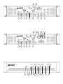
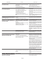
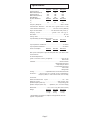
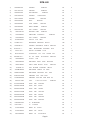
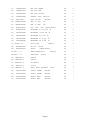
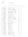
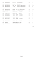
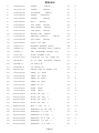
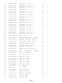
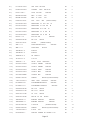
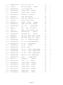
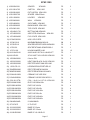
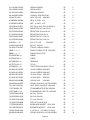
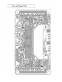
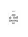
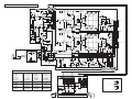
SERVICE MANUAL
XPM-600
XPM-900
XPM-1200
Power Amplifers
CONTENT’S:
Connections & Operations:.......................................................Page 2-5
Specifications:..............................................................................Page 6
Parts Lists:...............................................................................Page 8-20
PCBs:......................................................................................Page 21-22
Schematics:.................................................................................Page 23
Gemini Sound Products Corp.
120 Clover Place P.O. Box 6928
Edison, NJ 08818-6928
732-738-9003 (Phone) • 732-738-9006 (Fax)
Page 1
6
1
2
3
4
8
5
6
1
2
3
12
4
14
7
9
10
11
9
10
11
8
5
13
7
15
16 17 14
15
16 18
19
20
Stereo
Parallel Mono
Mono Bridge
Connections, Controls and Indicators
Rear Panel
Note: 120V and 230V units have different types of output
connectors on the rear panel.
Input Section:
There are two parallel input connectors (one female XLR and one
1/4” jack) per channel. Either can be used as an input or as a link to
chain amplifiers.
XLR Input Jacks (1, 5): electronically balanced inputs accept a standard
XLR male connector. Pin 1 = shield/ground, pin 2 = hot or positive (+)
and pin 3 = cold or negative (-).
1/4" Phone Input Jacks (2, 4): accept a balanced as well as an
unbalanced line level signal. The unbalanced line uses a standard tipsleeve connection. The tip is positive and the sleeve is negative/
ground. The balanced line uses a tip-ring-sleeve connection. Tip =
hot or positive (+), ring = cold or negative (-), and sleeve = shield/
ground.
Operation Mode Switch (3): switch is used to set the unit for Stereo
mode, Parallel Mono mode or Mono Bridge mode.
AC Power Section:
Fuse (7): replace fuse with those of proper type and rating.
Ground Lift Switch (8) is used to lift the ground from the chassis. See
the Ground Lift Switch Instructions for more detail.
Clip LED (15): the amplifier has true clip LEDs to help you properly
control the amplifier’s output and achieve undistorted sound. The clip
LEDs for each channel light when your signal level is so strong that
the distortion reaches 1% THD. The clip LED should not remain
constantly on or flash repeatedly during operation. For clean sound
reproduction, the clip should only light occasionally for an instant. If
the LED remains on or flashes repeatedly, you will hear distorted
sound that can be damaging to your speaker systems. If this occurs,
reduce the signal level by lowering the input level control for the
channel that is clipping or reduce the level at the source. If the clip
LED lights when no signal is present, it may indicate a RF signal on
the output which may cause damage to speakers (the RF signal will
not be audible). Please note that when you are using the amplifier in
the Mono Bridge mode, both clip LEDs of the bridged channels will
operate simultaneously.
Protect LED (16): when you first turn on the amplifier, the protect LEDs
light briefly during a turn-on delay which indicates that the outputs are
disconnected internally. There will be an audible click when the
outputs reconnect and the protect LEDs will turn off. Otherwise, the
protect LED indicates that there is a problem either in the amplifier’s
external connections, load or temperature conditions or its internal
functions. If one of these situations occur, the amplifier senses the
problem and automatically switches into protection mode. The LED
will light to warn you of the trouble and the amplifier will stop working.
If this occurs, switch off the amplifier and refer to the Trouble
Shooting Guide. If the protect LED remains lit when resuming
amplifier operation, do not use the amplifier and contact an
authorized service technician.
Level Controls (17, 18): establish the input levels required for each
channel. Only the Channel A Level Control (17) works in Mono
Bridge mode.
AC Cord Outlet (6) is used to attach the power cord to the unit.
Output Section:
Disconnect unit from the AC power source before making any
connections. Pay close attention to polarity (shown on the back of the
unit) when connecting your speakers. Connecting your speaker systems
using the wrong polarity will not damage your speakers, but it will impact
the quality of the sound (lack of bass and incorrect stereo image).
Speaker Outputs for 120V Unit (9, 10, 11): the speaker output jacks
are 5-way binding posts that will accept a standard banana plugs,
spade lugs or bare wire. Make sure that all the connections are clean
when using bare wire connections. If any strands of wire from one
connector touch the adjacent connector, the sound will be distorted,
and your amplifier will overheat and go into protection mode.
Speaker Outputs for 230V Unit (9, 10, 11): Neutrik Speakon
connectors are provided to connect speakers to the amplifier quickly
and easily. They are high current rated and provide very stable and
durable contacts. A third Speakon connector in the center is provided
to be used if the amplifier is in the Mono Bridge mode. Every
Speakon connector has pin 1- as negative and pin 1+ as positive.
NOTE: Total speaker impedance must not be lower than 4
Ohm per channel for Stereo and Parallel Mono modes, or 8
Ohm for Mono Bridge mode.
Operating Instructions
THE AMPLIFIER’S POWER MUST BE TURNED OFF WHEN
CHANGING MODES OF OPERATION.
Stereo Operation
The unit has two channels for stereo operation. Each channel
provides a separate and discrete signal at the speaker outputs according
to the signal received at the inputs. The following instructions are for
applications with 4 Ohm or 8 Ohm speakers of matched power ratings.
1. With the power off, set the OPERATION MODE SWITCH (3) to the
STEREO position. When the power is on, the Mono and Bridge LEDs
on the front panel will not light. If these LEDs illuminate, you have the
switch in the wrong position. Correct before continuing.
2. With the power off, connect your input cables to the channel A and B
inputs using either the XLR INPUT JACKS (1, 5) or 1/4" INPUT
JACKS (2, 4) of each channel. The other channel A and channel B
inputs can be used to link to an additional amplifier.
3. Connect the loudspeakers to the channel A and channel B SPEAKER
OUTPUTS (9, 11). THE TOTAL SPEAKER LOAD MUST BE AT
LEAST 4 OHMS PER CHANNEL. If you try to operate at a lower
impedance, the amplifier will go into protection mode and stop
operation until you correct the load conditions.
Front Panel
Power Switch (20): turns the unit on and off.
Power LED (19): the power LED lights when the power is on. If the
power LED does not light, refer to the trouble shooting guide.
Mono LED (12): the mono LED will light when you have set the rear
panel Operation Mode Switch (3) for parallel mono operation.
Always make sure that this switch is in the correct position and that
all speaker connections have been made correctly for the mode of
operation you wish to use before powering up the amplifier.
Bridge LED (13): the bridge LED will light when you have set the rear
panel Operation Mode Switch (3) for mono bridge operation. Always
make sure that this switch is in the correct position and that all
speaker connections have been made correctly for the mode of
operation you wish to use before powering up the amplifier.
4. With the LEVEL CONTROLS (17, 18) of both channels set to zero
(fully counterclockwise), turn the POWER SWITCH (20) on. Apply a
signal to the input of the amplifier. The level of the input signal should
be as high as you will ever need it to be. This way, it will be as high
above the amplifier’s noise floor as possible, ensuring an excellent
performance and signal to noise ratio. Adjust the LEVEL CONTROLS
for each channel to achieve the desired maximum listening level.
Note, when the clip LEDs light, there is distortion present in the
amplifier’s output section. If a clip LED remains on or flashes
repeatedly, reduce the signal level by lowering the input level control
for the channel that is clipping or reduce the level at the source.
Signal LED (14): the signal LEDs for each channel show when a signal
is present. In Mono Bridge mode, both the channel A LED and the
channel B LED will light in unison.
Page 4
Parallel Mono Operation
Using the Ground Lift Switch
Follow these instructions for Parallel Mono Operation using a single
input cable, and you will have the same monophonic signal on both the
channel A and the channel B outputs. Each channel’s output is
controlled independently by that channel’s level control.
Depending on your system configuration, sometimes applying the
ground will create a quieter signal path. Sometimes lifting the ground can
eliminate ground loops and hum to create a quieter signal path.
1. With the power amp on, listen to the system in idle mode (no signal
present) with the ground applied (the GROUND LIFT SWITCH (8) in
the left position).
1. With the power off, set the OPERATION MODE SWITCH (3) to the
PARALLEL MONO position. When the power is on, the MONO LED
(12) on the front panel will light. If the LED does not illuminate, you
have the switch in the wrong position. Correct before continuing.
2. Then turn the power off before moving the GROUND LIFT
SWITCH (8). Lift the ground by moving the GROUND LIFT SWITCH
to the right, turn the power back on and listen to determine which
position will provide a signal devoid of background noise and hum.
Keep the GROUND LIFT SWITCH in the ground position if the noise
level remains the same in either position.
2. With the power off, connect your input cables to the channel A input
only using the either the XLR INPUT JACK (5) or 1/4" INPUT JACK
(4) of channel A. The other channel A input can be used to link to an
additional amplifier.
3. Connect the loudspeakers to the channel A and channel B SPEAKER
OUTPUTS (9, 11). THE TOTAL SPEAKER LOAD MUST BE AT
LEAST 4 OHMS PER CHANNEL. If you try to operate at less than 4
Ohms per channel, the amplifier will go into the protection mode and
stop operation until you correct the load conditions.
CAUTION: DO NOT TERMINATE THE AC GROUND ON THE POWER
AMPLIFIER IN ANY WAY. TERMINATION OF THE AC GROUND CAN
BE HAZARDOUS.
4. With the LEVEL CONTROLS (17, 18) set to zero (fully
counterclockwise), switch the power on. Apply a signal to the input.
The level of the input signal should be as high as you will ever need it
to be. This way, it will be as high above the amplifier’s noise floor as
possible, ensuring an excellent performance and signal to noise ratio.
Adjust the LEVEL CONTROLS for each channel to achieve the
desired maximum listening level. Note, when the clip LEDs light,
there is distortion present in the amplifier’s output section. If a clip
LED remains on or flashes repeatedly, reduce the signal level by
lowering the input level control for the channel that is clipping or
reduce the level at the source.
Mono Bridge Operation
Follow these instructions to bridge the unit’s outputs. Bridging the
amplifier converts the unit to a monophonic or single channel. The
amplifier can be used with 8 Ohm or higher loads only in Mono Bridge
mode. This mode is used to provide a higher voltage with greater
headroom to your speaker. Before setting your amplifier for Mono Bridge
operation, make sure that your speaker can handle the high power level
provided by the amplifier in Mono Bridge mode. CAUTION: VOLTAGE
OVER 100 VOLTS MAY BE PRODUCED AT THE BRIDGE OUTPUT
TERMINALS IN THIS MODE.
1. With the power off, set the OPERATION MODE SWITCH (3) to the
BRIDGE position. When the power is on, the BRIDGE LED (13) on
the front panel will light. If the LED does not illuminate, you have the
switch in the wrong position. Correct before continuing.
2. With the power off, connect your input cables to channel A input only
using the either the XLR INPUT JACK (5) or 1/4" INPUT JACK (4) of
channel A. The other channel A input can be used to link to an
additional amplifier.
3. Connect the loudspeaker to the BRIDGE SPEAKER OUTPUT (10)
only. With a 230V unit, use the center speakon. With a 120V unit, use
the two innermost red terminals. Be sure the polarity of your
connections is correct. The total speaker load must be at least 8
Ohms or above. If you try to operate at less than 8 Ohms in the Mono
Bridge mode, the amplifier will go into the protection mode and stop
operation until you correct the load conditions.
4. With the CHANNEL A LEVEL CONTROL (17) set to zero (fully
counterclockwise), switch the power on. Apply a signal to the input.
The level of the input signal should be as high as you will ever need it
to be. This way, it will be as high above the amplifier’s noise floor as
possible, ensuring an excellent performance and signal to noise ratio.
Adjust the LEVEL CONTROL (17) for channel A to achieve the
desired maximum listening level. Note, when the clip LEDs light,
there is distortion present in the amplifier’s output section. If a clip
LED remains on or flashes repeatedly, reduce the signal level by
lowering the input level control for channel A or reduce the level at
the source. During Mono Bridge operation, the channel B level is
inactive, however, both channels LEDs will flash simultaneously and
show output conditions.
Page 5
SYMPTOM
UNIT DOES NOT PRODUCE SOUND. POWER
LED DOES NOT LIGHT.
CAUSE
• POWER SWITCH NOT IN ON POSITION.
• MOVE POWER SWITCH TO ON POSITION.
• POWER CABLE NOT CONNECTED TO AMPLIFIER
OR TO OUTLET.
• CONNECT POWER CABLE TO AC SUPPLY.
• AC OUTLET NOT ACTIVE.
• REPLACE AMPLIFIER MAIN POWER FUSE ON REAR
PANEL WITH CORRECT TYPE AND RATING.
• MAIN AMPLIFIER FUSE DEFECTIVE.
POWER LED LIGHTS, BUT NO SOUND IS
PRODUCED BY AMPLIFIER.
SOLUTION
• NO INPUT SOURCE SIGNAL.
• INPUT SOURCE NOT CONNECTED.
• INPUT CONNECTING CABLE DEFECTIVE.
• SPEAKER(S) NOT CONNECTED.
• SPEAKER CABLE DEFECTIVE.
• SPEAKER SYSTEM(S) INOPERATIVE.
• CHECK CONDITION OF OUTLET.
• CHECK FOR PROPER FUNCTION OF INPUT
SOURCE DEVICE.
• CHECK INPUT CABLES AND CONNECTIONS.
REPLACE QUESTIONABLE CABLES WITH KNOWN
GOOD CABLES.
• CHECK SPEAKER CABLES AND CONNECTIONS.
REPLACE QUESTIONABLE CABLES WITH KNOWN
GOOD CABLES.
• AMPLIFIER’S LEVEL CONTROLS ARE SET TO
ZERO.
• CHECK OPERATING CONDITION AND STATUS OF
SPEAKER SYSTEM(S). BE SURE THE LEVEL
CONTROLS ARE PROPERLY SET.
SOUND IS PRESENT BUT VOLUME IS TOO
LOW EVEN THOUGH SOURCE DEVICE IS
SET TO A HIGH LEVEL.
• AMPLIFIER INPUT LEVEL CONTROLS ARE SET
TOO LOW.
• ADJUST LEVEL CONTROLS AS PER INSTRUCTIONS.
LOUD 50/60 HZ OR 100/120 HZ HUM IS
HEARD AT ALL TIMES THROUGH THE
SPEAKER SYSTEMS.
• IMPROPER OR DEFECTIVE GROUND
CONNECTION AT INPUTS. IMPROPER OR
DEFECTIVE GROUND AT INPUT SOURCE
DEVICE(S).
• WRONG PIN CONNECTIONS IN CABLES.
• IMPROPER OR DEFECTIVE GROUND
CONNECTION ON AC OUTLET.
SOUND IS DISTORTED.
• USE CORRECT CABLES (AS SHOWN ON BACK OF
UNIT).
• CHECK FOR PROPER AC LINE GROUND ON POWER
AMP AND ALL INPUT DEVICES.
• CHECK INPUT CABLES FOR ALL SOURCE DEVICES
AND SIGNAL PROCESSING AS WELL AS INPUT
CABLES TO POWER AMPLIFIER. CHECK POSITION
OF GROUND LIFT SWITCH AS PER INSTRUCTIONS
FOR LIFTING THE GROUND.
• GROUND LOOP THROUGH AC LINE
CONNECTION/RACK MOUNTING.
• NEVER LIFT THE AC LINE GROUND ON THE POWER
AMPLIFIER. IF YOU ARE NOT TOTALLY FAMILIAR WITH
GROUND LIFTING OR UNIFICATION PROCEDURES,
DO NOT ATTEMPT THEM WITHOUT FIRST CONSULTING
YOUR DEALER OR A QUALIFIED SOUND
TECHNICIAN FOR MORE INFORMATION ON
GROUNDING. IMPROPERLY DONE, SUCH
PROCEDURES CAN POSE A SAFETY AND/OR FIRE
HAZARD.
• DISTORTION OCCURRING IN SOURCE DEVICE.
• CHECK CLIP INDICATORS ON INPUT SOURCE
DEVICES AND RESET LEVELS IF NECESSARY TO
ELIMINATE DISTORTION.
• INPUT LEVEL IS SET TOO HIGH.
• ADJUST LEVEL CONTROLS AS PER INSTRUCTIONS.
PROTECT LED REMAINS LIT OR GOES ON
AND OFF INTERMITTENTLY AFTER USING
AMPLIFIER FOR A SHORT TIME.
• UNIT IS OPERATING AT EXCESSIVELY HIGH
TEMPERATURE.
• EXTREMELY LOW SPEAKER IMPEDANCE.
• SHORT IN SPEAKER CONNECTORS, SPEAKER
CABLE OR SPEAKER SYSTEM.
• CHECK THAT AMPLIFIER IS ADEQUATELY
VENTILATED ON THE FRONT AND REAR PANELS
WHERE THE AIR VENTS AND FANS ARE LOCATED.
IF OVERHEATED, LET THE AMPLIFIER COOL DOWN
BEFORE APPLYING AN INPUT SIGNAL.
• CHECK THE POSITION OF OPERATION MODE
SWITCH. BE SURE THAT THE SPEAKER
CONNECTIONS ARE MADE IN ACCORDANCE WITH
THE SWITCH SETTING.
• VERIFY SPEAKER SYSTEM IMPEDANCES. BE SURE
THE TOTAL SPEAKER SYSTEM IMPEDANCE IS AT
LEAST 4 OHMS PER CHANNEL WHEN THE
OPERATION MODE SWITCH IS IN THE STEREO
POSITION OR PARALLEL MONO POSITION. IF THE
SWITCH IS IN THE BRIDGE MODE, THE IMPEDANCE
MUST BE AT LEAST 8 OHMS. IF YOU ARE NOT SURE
OF YOUR TOTAL SPEAKER IMPEDANCE LOAD,
CONTACT YOUR DEALER FOR MORE INFORMATION.
• CHECK CONDITION OF SPEAKER CABLES.
• IF USING BARE WIRE CONNECTIONS ON THE
OUTPUTS OF THE AMPLIFIER, BE SURE THAT NO
STRANDS FROM ONE CONNECTOR ARE TOUCHING
ANY OTHER CONNECTOR.
FUSE BLOWS INTERMITTENTLY.
• SPEAKER LOAD IMPEDANCE IS TOO LOW.
• CHECK FOR SHORTS ON THE OUTPUTS.
• TYPE OR RATING OF THE FUSE IS NOT
CORRECT.
• CHECK YOUR SPEAKER IMPEDANCE (INFO FROM
DEALER).
• CHECK THAT THE FUSE TYPE AND RATING IS
CORRECT.
PROTECT LED(S) STAY ON WITH NO
SPEAKERS CONNECTED AND WITH THE
AMPLIFIER COOLED DOWN.
• CONTACT THE GEMINI SERVICE DEPARTMENT OR
YOUR AUTHORIZED DEALER TO SPEAK TO A
QUALIFIED SERVICE TECHNICIAN. IN THE U.S.A.
CALL TOLL FREE 1-800-476-8633
• FAILED AMPLIFIER.
Page 6
Specifications
Output Power EIA: 1kHz @ 1% THD
XPM-600
Single Channel 8Ω
230
Both Channels Driven 8Ω
200
Single Channel 4Ω
300
Both Channels Driven 4Ω
270
Mono Bridge 8Ω
550
XPM-900
310
280
480
400
800
XPM-1200
400
360
630
530
1060
Dynamic Headroom:
XPM-600
XPM-900
XPM-1200
8Ω
1.4
1.4
1.3
4Ω
2.2
2.2
2.2
Frequency Response............................................................20 Hz - 60 kHz
Total Harmonic Distortion......less than 0.1%, typical 0.03% at 1 kHz
Intermodulation Distortion.......................less than 0.05% (SMPTE)
Signal to Noise Ratio..........................100 dB below rated power, 8Ω
Damping Factor..............................greater than 200 @ 8Ω
Slew Rate.................................................................................25 V/µS
Voltage Gain....................................................................33 dB
Input Sensitivity (for rated power at 8 Ohm):
XPM-600
0.9 Vrms
XPM-900
1.1 Vrms
XPM-1200
1.2 Vrms
Input Impedance Unbalanced....................................................10 kOhms
Input Impedance Balanced.......................................................20 kOhms
Power consumption:
XPM-600
XPM-900
XPM-1200
700 VA
900 VA
1100 VA
Note: power consumption is given at rated power at 8Ω per channel, both
channels driven.
AC Power Requirement:
(power connection is factory configured)............................120V/ 60 Hz
230V/ 50 Hz
Indicators.......................................................................1 Power Indicator
1 Signal LED per channel
1 Clip LED per channel
1 Protect LED per channel
1 Mono LED
1 Bridge LED
Cooling....................................2 Speed Dual Fan; Front-to-Rear Forced Air
Protection...........Short Circuit, DC, Thermal Cut-off, Sub/ultrasonic
Frequency Filters, In-rush Current Limiter, Turn-on Delay
Connectors:
Balanced/Unbalanced Inputs....................................1/4" Jack
Balanced Inputs............................................XLR Female Jack
Speaker Outputs (120V unit)..........................................5-way binding posts
Speaker Outputs (230V unit)...........Speakons (ch.A, ch.B and bridge)
Dimensions...................................19" x 13.75" x 3.5" (483 x 350 x 89 mm)
Weight
XPM-600
XPM-900
XPM-1200
25.8 lbs
29 lbs
31.2 lbs
11.7 kg
13.2 kg
14.2 kg
* Specifications and design are subject to change without notice for
purpose of improvement.
Page 7
XPM-600
1)
102056543301
SPACER
XPM-900
PC
2
2)
102119214701
CARTON
XPM-600
PC
1
3)
102260018001
EXT.CARTON
PC
1
4)
103012005700
SPACER
1200x570m/m
PC
1
5)
105011008501
HOLDER
XPM-900
PC
2
6)
105032409601
WALL
PC
1
7)
105034608501
SILD
PC
2
8)
105242608601
BACK BOARD
PC
1
9)
105343431801
TOP COVER
PC
1
PC
1
PC
1
PC
1
PC
5
CM
2
PC
4
PC
1
PC
12
PC
1
PC
1
PC
6
PC
1
PC
1
PC
9
PC
1
PC
1
PC
6
XPM-900
PANEL
10)
105443431701
BOTTOM
11)
107042002501
AIRFILTER
12)
107042004001
PVC COVER
13)
1070ACS03501
ACS-3.5
14)
1070KG-010—
M0VEABLE
15)
1070SCB-10—
SPACER
16)
1070SS-6——
SELF
XPM-900
XPM-900
RED
BUSHING
KG-010
SUPPORTS
SCB-10
RETATINING
18)
AL201AL50101
AL201/AL501
SS-6
YJ-98
SJT
INLET
XPM-900
SPALERS
CLAMPER
AC
XPM-900
XPM-600
PVC
NYLON
3P
XPM-600
420x25m/m
1070YJ-98—-
AO016D130—-
XPM-900
CABI
17)
19)
XPM-600
W-A
14AWG
AC-016D130
6FT
XPM-900
20)
105006400001
6.4m/m
21)
106203003003
RECTIFER
22)
106201302001
HEAT
23)
1070LED-3.5-
24)
700KBP060002
RECTIFIER
KBP06
25)
700MP3504W02
RECTIFIER
MP3504W
26)
CCN0A101250K
CERAMIC
27)
CCN0A680500J
CERAMIC CAP 68P 500V NPO 5%
PC
2
28)
COIL16115T6L
COIL
PC
2
29)
ECL04700080M
ELEC
CAP
4700u80v
PC
4
30)
ECS00010050M
ELEC
CAP
10u50v
PC
4
31)
ECS00100025M
ELEC
CAP
100u25v
PC
4
32)
ECS00100100M
ELEC
CAP
100u100v
PC
4
33)
ECS00220016M
ELEC
CAP
220u16v
PC
6
34)
ECS01000025M
ELEC
CAP
1000u25v
PC
1
35)
ECS02200025M
ELEC
CAP
2200u25v
PC
1
36)
ICNJM3404AD-
IC
NJM3404AD
PC
2
37)
ICTL072CP—-
IC
TL072CP
PC
1
PC
2
2.5m/m
PC
1
JS-1001R-02
PC
2
LED
PIN
HEAT
SINK
SINK
BLACK
SPACER
XPB-1600
13x20
SUPPORT
CAP
2A
100P
LED-3.5
600V
35A
JS1001025003
BASE
3P
39)
JS1001025012
BASE
12P
40)
JS1001R25002
BASE
2P
400V
250V
1.6x10.1x11.5T-6L
38)
XPM-900
2.5m/m
Page 8
XPM-900
41)
LDG050210030
LED 5m/m GREEN
PC
5
42)
LDR050410030
LDE 5m/m RED
PC
2
43)
LDY050610030
LDE 5m/m YELLOW
PC
2
44)
MJ0860250900
CONNOC
PC
2
PC
2
JACK
086-25-90
45)
MJCPJ-065—-
JACK
46)
MPMEA104250K
MEA
.1u
250V
10%
PC
6
47)
MPMEF104250K
MEF
.1u
250V
10%
PC
2
48)
NTM3x07x030Y
NUT
PC
1
49)
RC0200A47005
RESISTORS 4.7 ohm 2W
PC
2
50)
RC0201000005
RESISTORS 10 ohm 2W
PC
2
51)
RC0202230005
RESISTORS 22 K 2W
PC
2
52)
RC0204720005
RESISTORS 4.7 K 2W
M
PC
2
53)
RC0205620005
RESISTORS 5.6 K 2W
M
PC
2
832-1C-C-12D
XPM-900
PC
2
PC
1
PC
1
PC
1
PC
1
54)
RL832——12
CPJ-065
3m/m
55)
SR01MS3x061B
MS 3x6
56)
SR01TP4x204Y
TP4x20
XPM-900
W/S
(0J0010-030001)
M
M
M
BLACK
(1JBH6C-042021)
57) SWL————1
SS004-P2430Em-PC10
XPM-900
58) SWS————1
SS004-P022
59)
TRMJE340—0
MJE340
PC
2
60)
TRMJE350—0
MJE350
PC
2
61)
TRMPSA13—0
TR
PC
2
62)
TRTIP122—0
PC
1
63)
TRZ0103——0
PC
2
BY-PF8
MPSA13
TIP122
TRIAC
Z0103
MA1A600V
RR-15
64)
W20105135205
1015#14
GREEN
XPM-900
PC
1
65)
W20105185205
1015#14
GREEN
XPM-900
PC
1
66)
W20105235208
1015#14
GRAY
XPM-900
PC
1
67)
W20105375202
1015#14
RED
XPM-900
PC
1
Page 9
XPM-600E
STEREO
MOSFET POWER AMPUFIER
==================
=================================
=======
==============
==================
=================================
=======
==============
68)
W20105375202
1015#14
RED
XPM-900
PC
1
69)
W2120A3000BB
1007#26
MIX
XPM-900
PC
1
70)
WS204x10x07W
SPRING
PC
1
71)
106202602001
ALUMINUM
PC
4
72)
106219207601
HEAT
XPM-900
PC
2
XPM-900
PC
2
PC
2
PC
4
PC
4
PC
4
PC
8
XPM-600
PC
2
XPM-600
PC
2
PC
4
PC
10
PC
10
PC
4
PC
1
W/S.M4-L(2JS100-040050)
PLATE
SINK
26x20m/m
192x76x60
73)
PTH9M222—E2
PTH9M04BE222TS2F333
74)
PTH9M471—H1
PTH9M04BH471TS2F333
t=3
XPM-900
75)
SR01MS3x061B
MS 3x6
76)
SR01MS3x161W
MS
77)
SR01TP3x103B
TP
78)
SR03TP4x084B
FMT+W TP 4x8
79)
TRBUZ900NDP0
80)
TRBUZ905DP-0
BUZ905DP MOSFET
81)
WS132x08x10W
3.2x0.8x10
82)
WS203x08x05W
SPRING
83)
2SA970BL—0
TR
2SA970
84)
2SC2240BL—0
TR
2SC2240
85)
6003501950
XPM-900
86)
700033050001
ZENER
3.3v
500mw
PC
6
87)
700075050001
ZENER
7.5V
500mw
PC
1
88)
700120050001
ZENER
12V
500mw
PC
6
89)
700150050001
ZENER
15V
500mw
PC
1
90)
700150100001
ZENER 15V 1W
PC
2
91)
7001N4004051
DIODE
1N4004
PC
6
92)
7001N4148051
DIODE
1N4148
PC
13
93)
MCT0A102100J
MYLAR
CAP
.001u
T
PC
2
94)
MCT0A153100J
MYLAR
CAP
.015u
T
PC
2
95)
MCT0A182100J
MYLAR
CAP
.0018u
PC
2
96)
MCT0A473100J
MYLAR
CAP
.047u
PC
1
97)
MPMSC104100J
PC
15
98)
PC
4
99)
PC
21
PC
16
100)
BLACK
3x16
(1JBHMC-031600)
3x10
BLACK
BUZ900NDP
BLACK
MOSFET
(2IFA032-081000)
W/S.M3-L(2JS100-030050)
BL
BL
MAIN
PC
BOARD
T
T
MSC .1u 100V
5%
T
RC0031010005
RESISTORS
100
ohm
1/4W
RC0031020005
RESISTORS
1
RESISTORS
10
RC0031030005
K
1/4W
K
T=2oz
T
1/4W
T
Page 10
T
101)
RC0031040005
RESISTORS
100
K
1/4W
102)
RC0031050005
RESISTORS 1 M 1/4W
103)
RC0031520005
RESISTORS
1.5
PC
2
PC
1
PC
2
104)
RC0032020005
RESISTORS
2
PC
3
105)
RC0032210005
RESISTORS
220
PC
2
106)
RC0032230005
RESISTORS
22
K
1/4W
T
PC
2
107)
RC0033030005
RESISTORS
30
K
1/4W
T
PC
4
108)
RC0033040005
RESISTORS
300
K
1/4W
T
PC
2
109)
RC0033320005
RESISTORS
3.3
K
1/4W
T
PC
4
110)
RC0034700005
RESISTORS
47
ohm
PC
4
111)
RC0034730005
RESISTORS
47
K
PC
4
112)
RC0035110005
RESISTORS
510ohm
PC
4
113)
RC0036830005
RESISTORS
68
PC
4
114)
RC0038210005
RESISTORS
820
ohm
PC
2
115)
RC0038220005
RESISTORS
8.2
K
1/4W
T
PC
2
116)
RC0050A10005
RESISTORS
1
ohm
1/2W
T
PC
1
117)
RC0053030005
RESISTORS
30
K
1/2W
T
PC
2
118)
RC0054730005
RESISTORS
47
K
1/2W
T
PC
2
119)
RM0030K47501
RESISTORS
475
ohm
PC
2
120)
RM00310K0001
RESISTORS
10K
1%
PC
8
121)
105006400001
6.4m/m
PC
2
122)
6000680600
XPM-900 POWER PC BOARD T=oz
PC
1
PC
1
PC
1
1.2 K 5W SQP TYPE
PC
1
K
K
T
T
1/4W
T
1/4W
ohm
T
1/4W
1/4W
1/4W
K
T
T
T
1/4W
1/4W
T
T
1/4W
T
1/4W
T
1/4W
T
PIN
123)
MPMPX473275K
MPX
.047u
124)
NTC0120L
NTC
20A
275VAC
10%
SCK-0120
XPM-900
125)
RS0500122005
126)
W2010G130051
1015#14
BROWN
XPM-900E
PC
1
127)
W2010G180056
1015#14
BLUE
XPM-900E
PC
1
128)
FAD012080001
SP802512H
L=350m/m+XH
PC
2
129)
FH63032I
FUSE
HOLD
HTB-32I
PC
1
130)
FS630ULC060F
FUSE
6x30
PC
1
131)
FTSF-006
PLASTIC
PC
4
132)
IBXPM900—GI
MANUAL
PC
1
PC
2
PC
1
PC
1
PC
1
PC
2
PC
10
PC
1
FAST/GLASS
FOOT
KB1819BL0001
KNOB
134)
NTM8x17x080B
NUT
135)
PB420215
PLOY
BAG
136)
PT130———2
TRANS.
130m/m
SR01MS3x042B
MST
138)
SR01MS3x061B
MS
139)
SR01MS3x121B
MS
18x19
BLACK
5/16
3x4
3x6
3x12
TYPE
U/C
6A
SF-006
XPM-900
133)
137)
VDE
(GEMINI)
XPM-900
(0A0220-310005)
8.5"x16.5"X0.05
XPM-600E
230V
BLACK(1JPH1C-030424)
BLACK(1JBHMC-030604)
BLACK
Page 11
140)
SR01MS3x081W
MS
3x8
141)
SR01MS4x061W
MS
142)
SR01MS4x082B
MST
143)
SR01TP3x063B
TP
144)
SR01TP3x103B
TP
145)
SR03TP4x084B
FMT+W
146)
SR10MS8x751B
5/16x3"
4x6
(1JPHMC-030800)
PC
1
(PLATING)
PC
1
4x8
BLACK
(1JBH1C-040824)
PC
16
3x6
BLACK
(1JBHCC-030625)
PC
6
3x10
BLACK
(1JBHCC-031024)
PC
4
PC
14
PC
1
PC
1
PC
2
TP
4x8
(1JBP6C-040825)
(1ATKMO-31C004)
147) SWP————9
R22-22B-11B
148)
VR16A1031501
16K4x1
149)
W2010G445101
1015#14
BROWN
XPM-900E
PC
1
150)
W2010G505106
1015#14
BLUE
XPM-900E
PC
1
151)
W2010I12510A
1015#18
GR+YL
PC
1
152)
W20110120101
1015#14
BROWN
XPM-900E
PC
1
153)
W5010A370032
2852#26
RED
XPM-900
PC
1
154)
W5010A460038
2852#26
GRAY
XPM-900
PC
1
GEMINI WARRANTY CARD
PC
1
EXT
PC
1
155)
156)
WDGEMINI
WS407x03x09Y
XPM-900
L-15
TOOTH
XPM-900
W/S.
3m/m
465
Page 12
XPM-900
1 )
102056543301
SPACER
XPM-900
PC
2
2 )
102119214702
CARTON
PC
1
3 )
102260018002
EXT.CARTON
PC
1
4 )
103012005700
SPACER
1200x570m/m
PC
1
5 )
105011008501
HOLDER
XPM-900
PC
2
6 )
105032409601
WALL
PC
1
7 )
105034608501
SILD
PC
2
8 )
105242608603
BACK BOARD
PC
1
9 )
105343431801
TOP COVER
PC
1
1 0 )
105443431701
BOTTOM
PC
1
1 1 )
107042002501
AIRFILTER
PC
1
1 2 )
107042004002
PVC COVER
PC
1
1 3 )
1070ACS03501
ACS-3.5
PC
5
1 4 )
1070KG-010—
M0VEABLE
CM
2
1 5 )
1070SCB-10—
SPACER
PC
4
1 6 )
1070SS-6——
SELF
PC
1
1 7 )
1070YJ-98—-
NYLON
PC
12
1 8 )
AL201AL50101
AL201/AL501
PC
1
1 9 )
AO016D130—-
3P
AC
PC
1
2 0 )
2SA970BL—0
TR
2SA970
PC
10
2 1 )
2SC2240BL—0
TR
2SC2240
PC
4
2 2 )
6003501950—
XPM-900
PC
1
2 3 )
700033050001
ZENER
3.3v
500mw
PC
6
2 4 )
700075050001
ZENER
7.5V
500mw
PC
1
2 5 )
700120050001
ZENER
12V
500mw
PC
6
2 6 )
700150050001
ZENER
15V
500mw
PC
1
2 7 )
700150100001
ZENER 15V 1W
PC
2
2 8 )
7001N4004051
DIODE
1N4004
PC
6
2 9 )
7001N4148051
DIODE
1N4148
PC
13
3 0 )
MCT0A102100J
MYLAR
CAP
.001u
T
PC
2
3 1 )
MCT0A153100J
MYLAR
CAP
.015u
T
PC
2
3 2 )
MCT0A182100J
MYLAR
CAP
.0018u
PC
2
3 3 )
MCT0A473100J
MYLAR
CAP
.047u
PC
1
3 4 )
MPMSC104100J
MSC .1u 100V
5%
T
PC
15
3 5 )
RC0031010005
RESISTORS
100
ohm
1/4W
PC
4
3 6 )
RC0031020005
RESISTORS
1
PC
21
3 7 )
RC0031030005
RESISTORS
10
PC
16
3 8 )
RC0031040005
RESISTORS
100
PC
2
3 9 )
RC0031050005
RESISTORS 1 M 1/4W
PC
1
4 0 )
RC0031520005
RESISTORS
PC
2
XPM-900
XPM-900
XPM-900
PANEL
XPM-900
XPM-900
XPM-900
CABI
XPM-900
420x25m/m
XPM-900
XPM-900
PVC
RED
BUSHING
KG-010
SUPPORTS
SCB-10
RETATINING
CLAMPER
SPALERS
SS-6
YJ-98
SJT
INLET
XPM-900
W-A
14AWG
AC-016D130
6FT
XPM-900
BL
BL
MAIN
PC
K
1.5
BOARD
T
T
1/4W
K
K
T
1/4W
1/4W
T
T
1/4W
K
T=2oz
T
T
T
Page 13
4 1 )
RC0032020005
RESISTORS
2
K
1/4W
T
PC
3
4 2 )
RC0032210005
RESISTORS
220
PC
2
4 3 )
RC0032230005
RESISTORS
22
K
1/4W
T
PC
2
4 4 )
RC0033030005
RESISTORS
30
K
1/4W
T
PC
4
4 5 )
RC0033040005
RESISTORS
300
K
1/4W
T
PC
2
4 6 )
RC0033320005
RESISTORS
3.3
K
1/4W
T
PC
4
4 7 )
RC0034700005
RESISTORS
47
ohm
PC
4
4 8 )
RC0034730005
RESISTORS
47
K
PC
4
4 9 )
RC0035110005
RESISTORS
510ohm
PC
4
5 0 )
RC0036830005
RESISTORS
68
PC
4
5 1 )
RC0038210005
RESISTORS
820
ohm
PC
2
5 2 )
RC0038220005
RESISTORS
8.2
K
1/4W
T
PC
2
5 3 )
RC0050A10005
RESISTORS
1
ohm
1/2W
T
PC
1
5 4 )
RC0053030005
RESISTORS
30
K
1/2W
T
PC
2
5 5 )
RC0054730005
RESISTORS
47
K
1/2W
T
PC
2
5 6 )
RM0030K47501
RESISTORS
475
ohm
PC
2
5 7 )
RM00310K0001
RESISTORS
10K
1%
PC
8
5 8 )
105006400001
6.4m/m
PC
6
5 9 )
106201302001
HEAT
PC
1
6 0 )
106203003003
RECTIFER
XPB-1600
PC
1
6 1 )
1070LED-3.5-
LED
LED-3.5
PC
9
6 2 )
700KBP060002
RECTIFIER
KBP06
PC
1
6 3 )
700MP3504W02
RECTIFIER
MP3504W
PC
1
6 4 )
CCN0A101250K
CERAMIC
PC
6
6 5 )
CCN0A680500J
CERAMIC CAP 68P 500V NPO 5%
PC
2
6 6 )
COIL16115T6L
COIL
PC
2
6 7 )
ECL06800100M
ELEC
CAP
PC
4
6 8 )
ECS00010050M
ELEC
CAP
10u50v
PC
4
6 9 )
ECS00100025M
ELEC
CAP
100u25v
PC
4
7 0 )
ECS00100100M
ELEC
CAP
100u100v
PC
4
7 1 )
ECS00220016M
ELEC
CAP
220u16v
PC
6
7 2 )
ECS01000025M
ELEC
CAP
1000u25v
PC
1
7 3 )
ECS02200025M
ELEC
CAP
2200u25v
PC
1
7 4 )
ICNJM3404AD-
IC
NJM3404AD
PC
2
7 5 )
ICTL072CP—-
IC
TL072CP
PC
1
7 6 )
JS1001025003
BASE
3P
PC
2
7 7 )
JS1001025012
BASE
12P
2.5m/m
PC
1
7 8 )
JS1001R25002
BASE
2P
JS-1001R-02
PC
2
7 9 )
LDG050210030
LED 5m/m GREEN
PC
5
8 0 )
LDR050410030
LDE 5m/m RED
PC
2
ohm
1/4W
1/4W
T
1/4W
K
T
T
1/4W
1/4W
T
T
1/4W
T
1/4W
T
1/4W
T
PIN
SINK
BLACK
HEAT
SPACER
13x20
SINK
SUPPORT
CAP
2A
100P
XPM-900
600V
35A
400V
250V
1.6x10.1x11.5T-6L
6800u100v
2.5m/m
Page 14
XPM-900
8 1 )
LDY050610030
LDE 5m/m YELLOW
PC
2
8 2 )
MJ0860250900
CONNOC
PC
2
8 3 )
MJCPJ-065—-
JACK
PC
2
8 4 )
MPMEA104250K
MEA
.1u
250V
10%
PC
6
8 5 )
MPMEF104250K
MEF
.1u
250V
10%
PC
2
8 6 )
NTM3x07x030Y
NUT
PC
1
8 7 )
RC0200A47005
RESISTORS 4.7 ohm 2W
PC
2
8 8 )
RC0201000005
RESISTORS 10 ohm 2W
PC
2
8 9 )
RC0202230005
RESISTORS 22 K 2W
PC
2
9 0 )
RC0204720005
RESISTORS 4.7 K 2W
M
PC
2
9 1 )
RC0205620005
RESISTORS 5.6 K 2W
M
PC
2
9 2 )
RL832——12
832-1C-C-12D
XPM-900
PC
2
9 3 )
SR01MS3x061B
MS 3x6
PC
1
9 4 )
SR01TP4x204Y
TP4x20
PC
1
9 5 )
SWL————1
SS004-P2430Em-PC10
PC
1
9 6 )
SWS————1
SS004-P022
PC
1
9 7 )
TRMJE340—0
MJE340
PC
2
9 8 )
TRMJE350—0
MJE350
PC
2
9 9 )
TRMPSA13—0
TR
PC
2
100)
TRTIP122—0
TIP122
PC
1
101)
TRZ0103——0
TRIAC
PC
2
102)
W20105135205
1015#14
GREEN
XPM-900
PC
1
103)
W20105185205
1015#14
GREEN
XPM-900
PC
1
104)
W20105235208
1015#14
GRAY
XPM-900
PC
1
105)
W20105375202
1015#14
RED
XPM-900
PC
1
106)
W2120A3000BB
1007#26
MIX
XPM-900
PC
1
107)
WS204x10x07W
SPRING
PC
1
108)
106219207601
HEAT
XPM-900
PC
2
109)
PTH9M222—E2
PTH9M04BE222TS2F333
XPM-900
PC
2
110)
PTH9M471—H1
PTH9M04BH471TS2F333
PC
2
111)
SR01MS3x061B
MS 3x6
BLACK
PC
4
112)
SR01MS3x121B
MS
3x12
BLACK
PC
12
113)
SR01TP3x103B
TP
3x10
BLACK
PC
4
114)
SR03TP4x084B
FMT+W TP 4x8
PC
4
115)
TRBUZ901P—0
BUZ901P MOSFET
XPM-900
PC
6
116)
TRBUZ906P—0
BUZ906P MOSFET
XPM-900
PC
6
117)
WS132x08x10W
3.2x0.8x10
PC
12
118)
WS203x08x05W
SPRING
PC
16
119)
105006400001
6.4m/m
PC
2
120)
6000680600—
XPM-900 POWER PC BOARD T=oz
PC
1
JACK
086-25-90
CPJ-065
3m/m
XPM-900
W/S
(0J0010-030001)
M
M
M
BLACK
(1JBH6C-042021)
XPM-900
BY-PF8
MPSA13
Z0103
MA1A600V
W/S.M4-L(2JS100-040050)
SINK
192x76x60
XPM-900
BLACK
(2IFA032-081000)
W/S.M3-L(2JS100-030050)
PIN
Page 15
121)
MPMPX473275K
MPX
.047u
122)
NTC0120L
NTC
20A
123)
RS0500122005
124)
275VAC
10%
PC
1
PC
2
1.2 K 5W SQP TYPE
PC
1
W2010G130050
1015#14
BLACK
XPM-900U
PC
1
125)
W2010G180059
1015#14
WHITE
XPM-900U
PC
1
126)
FAD012080001
SP802512H
L=350m/m+XH
PC
2
127)
FH630207D
FUSE
HOLD
CQ-207D
PC
1
128)
FS630ULC120F
FUSE
6x30
FAST/GLASS
PC
1
129)
FTSF-006
PLASTIC
PC
4
130)
IBXPM900—GI
MANUAL
PC
1
131)
KB1819BL0001
KNOB
PC
2
132)
NTM8x17x080B
NUT
PC
1
133)
PB420215
PLOY
BAG
PC
1
134)
PT160———2
TRANS.
160m/m
PC
1
135)
SPK1047R2001
WIN-1047R2
R/B
XPM-900
PC
1
136)
SPK1047R2002
WTN-1047R2
B/R
XPM-900
PC
1
137)
SPKCOVER—1
WIN-1047R2
COVER
PC
1
138)
SPKCOVER—2
WIN-1047R2
COVER
PC
1
139)
SR01MS3x042B
MST
PC
2
140)
SR01MS3x061B
MS
PC
10
141)
SR01MS3x081W
MS
(1JPHMC-030800)
PC
1
142)
SR01MS4x061W
MS
4x6
(PLATING)
PC
1
143)
SR01MS3x121B
MS
3x12
PC
1
144)
SR01MS4x082B
MST
145)
SR01TP3x063B
TP
146)
SR01TP3x103B
TP
147)
SR03TP4x084B
FMT+W
148)
SR10MS8x751B
5/16x3"
149)
SWP————9
R22-22B-11B
150)
VR16A1031501
16K4x1
151)
W2010G445100
1015#14
BLACK
152)
W2010G505109
1015#14
153)
W2010I12510A
154)
SCK-0120
FOOT
XPM-900
12A
SF-006
XPM-900
18x19
U/C
(GEMINI)
BLACK
5/16
XPM-900
(0A0220-310005)
8.5"x16.5"X0.05
3x4
XPM-900U
120V
BLACK
RED
XPM-900
XPM-900
BLACK(1JPH1C-030424)
3x6
BLACK(1JBHMC-030604)
3x8
BLACK
4x8
BLACK
(1JBH1C-040824)
PC
16
3x6
BLACK
(1JBHCC-030625)
PC
6
3x10
BLACK
(1JBHCC-031024)
PC
4
PC
14
PC
1
PC
1
PC
2
XPM-900U
PC
1
WHITE
XPM-900U
PC
1
1015#18
GR+YL
PC1800
PC
1
W20110120100
1015#14
BLACK
XPM-900U
PC
1
155)
W5010A370032
2852#26
RED
XPM-900
PC
1
156)
W5010A460038
2852#26
GRAY
XPM-900
PC
1
TP
4x8
(1JBP6C-040825)
(1ATKMO-31C004)
L-15
XPM-900
XPM-900
Page 16
XPM-1200
1) 102056543301
SPACER
2) 102119214703
CARTON
3) 102260018003
XPM-900
PC
2
PC
1
EXT.CARTON XPM-1200
PC
1
4) 103012005700
SPACER 1200x570m/m
PC
1
5) 105011008501
HOLDER
PC
2
6) 105032409601
WALL
PC
1
7) 105034608501
SILD PANEL XPM-900
PC
2
8) 105242608605
BACK BOARD XPM-1200
PC
1
9) 105343431801
TOP COVER XPM-900
PC
1
10) 105443431701
BOTTOM CABI XPM-900
PC
1
11) 107042002501
AIRFILTER 420x25m/m
PC
1
12) 107042004003
PVC COVER XPM-1200
PC
1
13) 1070ACS03501
ACS-3.5 PVC RED
PC
5
14) 1070KG-010
M0VEABLE BUSHING KG-010
CM
2
15) 1070SCB-10
SPACER SUPPORTS SCB-10 XPM-900
PC
4
16) 1070SS-6
SELF RETATINING SPALERS SS-6
PC
1
17) 1070YJ-98
NYLON CLAMPER YJ-98
PC
12
18) AL201AL50101
AL201/AL501 SJT W-A 14AWG 6FT
PC
1
19) AO016D130
3P AC INLET AC-016D130 XPM-900
PC
1
20) 105006400001
6.4m/m PIN
PC
6
21) 106201302001
HEAT SINK BLACK 13x20 XPM-900
PC
1
22) 106203003003
RECTIFER HEAT SINK XPB-1600
PC
1
23) 1070LED-3.5-
LED SPACER SUPPORT LED-3.5
PC
9
24) 700KBP060002
RECTIFIER KBP06 2A 600V
PC
1
25) 700MP3504W02
RECTIFIER MP3504W 35A 400V
PC
1
26) CCN0A101250K
CERAMIC CAP 100P 250V
PC
6
27) CCN0A680500J
CERAMIC CAP 68P 500V NPO 5%
PC
4
28) COIL16115T6L
COIL 1.6x10.1x11.5T-6L XPM-900
PC
2
29) ECL06800100M
ELEC CAP 6800u100v
PC
4
30) ECS00010050M
ELEC CAP 10u50v
PC
4
31) ECS00100025M
ELEC CAP 100u25v
PC
4
32) ECS00100100M
ELEC CAP 100u100v
PC
4
33) ECS00220016M
ELEC CAP 220u16v
PC
6
34) ECS01000025M
ELEC CAP 1000u25v
PC
1
35) ECS02200025M
ELEC CAP 2200u25v
PC
1
36) ICNJM3404AD-
IC NJM3404AD
PC
2
37) ICTL072CP
IC TL072CP
PC
1
38) JS1001025003
BASE 3P 2.5m/m
PC
2
39) JS1001025012
BASE 12P 2.5m/m
PC
1
40) JS1001R25002
BASE 2P JS-1001R-02
PC
2
XPM-1200
XPM-900
XPM-900
XPM-900
Page 17
41) LDG050210030
LED 5m/m GREEN
PC
5
42) LDR050410030
LDE 5m/m RED
PC
2
43) LDY050610030
LDE 5m/m YELLOW
PC
2
44) MJ0860250900
CONNOC JACK 086-25-90
PC
2
45) MJCPJ-065—-
JACK CPJ-065
PC
2
46) MPMEA104250K
MEA .1u 250V 10%
PC
6
47) MPMEF104250K
MEF .1u 250V 10%
PC
2
48) NTM3x07x030Y
NUT 3m/m W/S (0J0010-030001)
PC
1
49) RC0200A47005
RESISTORS 4.7 ohm 2W M
PC
2
50) RC0201000005
RESISTORS 10 ohm 2W M
PC
2
51) RC0202230005
RESISTORS 22 K 2W M
PC
2
52) RC0204720005
RESISTORS 4.7 K 2W M
PC
2
53) RC0205620005
RESISTORS 5.6 K 2W M
PC
2
54) RL832——12
832-1C-C-12D
PC
2
55) SR01MS3x061B
MS 3x6 BLACK
PC
1
56) SR01TP4x204Y
TP4x20 (1JBH6C-042021)
PC
1
57)SWL————1
SS004-P2430Em-PC10 XPM-900
PC
1
58)SWS————1
SS004-P022 BY-PF8
PC
1
59) TRMJE340—0
MJE340
PC
2
60) TRMJE350—0
MJE350
PC
2
61) TRMPSA13—0
TR MPSA13
PC
2
62) TRTIP122—0
TIP122
PC
1
63) TRZ0103——0
TRIAC Z0103 MA1A600V RR-15
PC
2
64) W20105135205
1015#14 GREEN XPM-900
PC
1
65) W20105185205
1015#14 GREEN XPM-900
PC
1
66) W20105235208
1015#14 GRAY XPM-900
PC
1
67) W20105375202
1015#14 RED
XPM-900
PC
1
68) W2120A3000BB
1007#26 MIX
XPM-900
PC
1
69) WS204x10x07W
SPRING W/S.M4-L(2JS100-040050)
PC
1
70) 106219207601
HEAT SINK 192x76x60 XPM-900
PC
2
71) PTH9M222—E2
PTH9M04BE222TS2F333 XPM-900
PC
2
72) PTH9M471—H1
PTH9M04BH471TS2F333 XPM-900
PC
2
73) SR01MS3x061B
MS 3x6 BLACK
PC
4
74) SR01MS3x121B
MS 3x12 BLACK
PC
8
75) SR01TP3x103B
TP 3x10 BLACK
PC
4
76) SR03TP4x084B
FMT+W TP 4x8 BLACK
PC
4
77) TRBUZ901NDP0
BUZ901NDP MOSFET XPM-1200
PC
4
78) TRBUZ906DP-0
BUZ906DP MOSFET
XPM-1200
PC
4
79) WS132x08x10W
3.2x0.8x10 (2IFA032-081000)
PC
8
80) WS203x08x05W
SPRING W/S.M3-L(2JS100-030050)
PC
12
XPM-900
XPM-900
Page 18
81) 2SA970BL—0
TR 2SA970 BL
PC
10
82) 2SC2240BL—0
TR 2SC2240 BL
PC
4
83) 6003501950—
XPM-900 MAIN PC BOARD T=2oz
PC
1
84) 700033050001
ZENER 3.3v 500mw
PC
6
85) 700075050001
ZENER 7.5V 500mw
PC
1
86) 700120050001
ZENER 12V 500mw
PC
6
87) 700150050001
ZENER 15V 500mw
PC
1
88) 700150100001
ZENER 15V 1W
PC
2
89) 7001N4004051
DIODE 1N4004
PC
6
90) 7001N4148051
DIODE 1N4148
PC
13
91) MCT0A102100J
MYLAR CAP .001u T
PC
2
92) MCT0A153100J
MYLAR CAP .015u T
PC
2
93) MCT0A182100J
MYLAR CAP .0018u T
PC
2
94) MCT0A473100J
MYLAR CAP .047u T
PC
1
95) MPMSC104100J
MSC .1u 100V 5% T
PC
15
96) RC0031010005
RESISTORS 100 ohm 1/4W T
PC
4
97) RC0031020005
RESISTORS 1 K 1/4W T
PC
21
98) RC0031030005
RESISTORS 10 K 1/4W T
PC
16
99) RC0031040005
RESISTORS 100 K 1/4W T
PC
2
100) RC0031050005
RESISTORS 1 M 1/4W T
PC
1
101) RC0031520005
RESISTORS 1.5 K 1/4W T
PC
2
102) RC0032020005
RESISTORS 2 K 1/4W T
PC
3
103) RC0032210005
RESISTORS 220 ohm 1/4W T
PC
2
104) RC0032230005
RESISTORS 22 K 1/4W T
PC
2
105) RC0033030005
RESISTORS 30 K 1/4W T
PC
4
106) RC0033040005
RESISTORS 300 K 1/4W T
PC
2
107) RC0033320005
RESISTORS 3.3 K 1/4W T
PC
4
108) RC0034700005
RESISTORS 47 ohm 1/4W T
PC
4
109) RC0034730005
RESISTORS 47 K 1/4W T
PC
4
110) RC0035110005
RESISTORS 510ohm 1/4W T
PC
4
111) RC0036830005
RESISTORS 68 K 1/4W T
PC
4
112) RC0038210005
RESISTORS 820 ohm 1/4W T
PC
2
113) RC0038220005
RESISTORS 8.2 K 1/4W T
PC
2
114) RC0050A10005
RESISTORS 1 ohm 1/2W T
PC
1
115) RC0053030005
RESISTORS 30 K 1/2W T
PC
2
116) RC0054730005
RESISTORS 47 K 1/2W T
PC
2
117) RM0030K47501
RESISTORS 475 ohm 1/4W T
PC
2
118) RM00310K0001
RESISTORS 10K 1% 1/4W T
PC
8
119) 105006400001
6.4m/m PIN
PC
2
120) 6000680600—
XPM-900 POWER PC BOARD T=oz
PC
1
Page 19
121) MPMPX473275K
MPX .047u 275VAC 10%
PC
1
122) NTC0120L——
NTC 20A SCK-0120 XPM-900
PC
2
123) RS0500122005
1.2 K 5W SQP TYPE
PC
1
124) W2010G130050
1015#14 BLACK XPM-900U
PC
1
125) W2010G180059
1015#14 WHITE XPM-900U
PC
1
126) FAD012080001
SP802512H L=350m/m+XH
PC
2
127) FH630207D—-
FUSE HOLD CQ-207D
PC
1
128) FS630ULC150F
FUSE 6x30 FAST/CERAMIC U/C 15A
PC
1
129) FTSF-006——
PLASTIC FOOT SF-006
PC
4
130) IBXPM900—GI
MANUAL XPM-900 (GEMINI)
PC
1
131) KB1819BL0001
KNOB 18x19 BLACK XPM-900
PC
2
132) NTM8x17x080B
NUT 5/16 (0A0220-310005)
PC
1
133) PB420215——
PLOY BAG 8.5"x16.5"X0.05
PC
1
134) PT160———4
TRANS. 160m/m XPM-1200U 120V
PC
1
135) SPK1047R2001
WIN-1047R2 R/B
XPM-900
PC
1
136) SPK1047R2002
WTN-1047R2 B/R
XPM-900
PC
1
137) SPKCOVER—1
WIN-1047R2 COVER BLACK XPM-900
PC
1
138) SPKCOVER—2
WIN-1047R2 COVER RED XPM-900
PC
1
139) SR01MS3x042B
MST 3x4 BLACK(1JPH1C-030424)
PC
2
140) SR01MS3x061B
MS 3x6 BLACK(1JBHMC-030604)
PC
10
141) SR01MS3x081W
MS 3x8 (1JPHMC-030800)
PC
1
142) SR01MS3x121B
MS 3x12 BLACK
PC
1
143) SR01MS4x061W
MS 4x6
PC
1
144) SR01MS4x082B
MST 4x8 BLACK (1JBH1C-040824)
PC
16
145) SR01TP3x063B
TP 3x6
BLACK (1JBHCC-030625)
PC
6
146) SR01TP3x103B
TP 3x10 BLACK (1JBHCC-031024)
PC
4
147) SR03TP4x084B
FMT+W TP 4x8 (1JBP6C-040825)
PC
14
148) SR10MS8x751B
5/16x3" (1ATKMO-31C004)V3000
PC
1
149)SWP————9
R22-22B-11B
PC
1
150) VR16A1031501
16K4x1 L-15
PC
2
151) W2010G445100
1015#14 BLACK XPM-900U
PC
1
152) W2010G505109
1015#14 WHITE XPM-900U
PC
1
153) W2010I12510A
1015#18 GR+YL
PC
1
154) W20110120100
1015#14 BLACK XPM-900U
PC
1
155) W5010A370032
2852#26 RED
XPM-900
PC
1
156) W5010A460038
2852#26 GRAY XPM-900
PC
1
157) WDGEMINI——
GEMINI WARRANTY CARD
PC
1
158) WS407x03x09Y
EXT TOOTH W/S. 3m/m
PC
1
(PLATING)
XPM-900
XPM-900
Page 20
3
2
1
3
3
2
1
3
R47
47
+ VCC
C19
0.1
C25
100/100V
R39
47K
R25
100
D9
1N4148
IC2A
R57
10K 1%
2
R59
10K 1%
3
C33
100
X23
TRS 1/4" BAL
Q6
MJE350
C14
0.1
1
TL072CP
+
R54
10K 1%
D5
1N4148
- 15V
R49
NU
R48
4K7 2W
C32
0.1
C28
100/25V
C22
10/50V
Q10
2SA970
R44
1K
R34
47K 1/2W
R18
10K
R45
47K
R38
1K
C40
10/50V
R12
1K
SW2 - STEREO
SW2A
SS004-P243O-PC10
1
2
3
SW2B
6
13
11
8
D1
1N4004
3.3V
Q4
2SC2240
ZD3
1N5242B
10
Q5
2SA970
ZD5
1N5242B
D6
1N4148
R2
475 1%
12
14
16
R19
10K
ZD1
1N5226B
3.3V
12V
3.3V
ZD6
1N5226B
R40
3K3
C23
100/100V
R41
3K3
R15
820
R13
4,7 2W
D2
1N4004
C11 1 /160V
R35
220
FET4
FET5
R7
1K
R8
1K
RLY1
T90S5D12-12
2D8
1N4004
FET6
C9
0.1
X2
NL4MD-H
(230V ONLY)
2+
Q3
MPSW45A
R9
100K
R1
30K 1/2W
R16
68K
R46
47
OUTPUT CH A
1-
RT1
PTC 90C
330 @ 25C
D7
1N4148
R6
1K
1+
5
BRIDGE
C20
0.1
X5
NU
1
Q9
2SC2240
5
X3
NU
X4
NU
4
Q7
MJE340
MONO
Q2
2SA970
12V
C8
68
STEREO
15
R11
10 2W
L1
SW2D
9
7
4
4
SW2C
5
2
3
C15
100
C18
100/25V
1
FET3
D3
1N4148
C13
0.1
C10
0.1
C17
1000
R5
1K
FET2
1.2 uH
D4
1N4148
ZD9
1N5245B -15V
Q12
2SA970
R4
1K
FET1
R32
22K 2W
ZD2
1N5226B
4
T
R
S
R10
68K
R3
1K
-
2
R26
100
3
3
CH A
X25
C24
10/50V
2
1
+ 15V
X19.1
X8
2
C31
100
XLR1
XLF-3PH
X8.1
1
3
R53
10K 1%
- 15V
2
1
X12
NU
2
1
Schematic
C1
220/10V
Q1
L201E3
C2
220/10V
C7
220/10V
R14
22K
R17
1K5
- VCC
R67
47K
X26
TRS 1/4" BAL
C48
0.1
7
TL072CP
5
ZD16
1N5226B
8
D11
1N4148
+ 15V
R50
4K7 2W
C30
0.1
C29
100/25V
C38
10/50V
Q13
2SA970
Q14
2SA970
R63
1K
R74
47K 1/2W
C45
1000
R94
1K
ground
4
6
1
3
C49
100
lift
C41
100/25V
R52
R102
1K
X29
NU
FET9
D17
1N4004
D12
1N4148
R105
475 1%
1
ZD14
1N5226B
3.3V
12V
3.3V
RT3
PTC 90C
330 @ 25C
ZD13
1N5226B
D13
1N4148
R91
820
R95
4,7 2W
D18
1N4004
Q17
MJE340
FET10
R106
1K
Q15
2SC2240
F1
BLK
*
C43
0.1
C21
C44
C26
C36
C3
C59
0.1
0.1
C4
C60
0.1
0.1
X16.1 X16
GRY
R65
3K3
C39
100/100V
+ VCC
X20.1 X20
YEL
R1
1.2K 5W
P3
REC1
MP3504W
X14.1 X14
BLU
X19.1 X19
RED
ORN 120V
BLU 230V
N20SP0R7-Q 12A
SW3
*
X1.1
R66
3K3
R69
220
RLY2
T90S5D12-12
OUTPUT CH B
1-
X10
NL4MD-H
(230V ONLY)
2+
2
N20SP0R7-Q 12A
RT1
BLK
BLK
P1
X1
1+
5
ZD12
1N5242B
R103
1K
FET11
R104
1K
R107
30K 1/2W
C50
0.1
R92
68K
R55
47
R99
100K
2Q21
MPSW45A
D16
1N4004
FET12
C54 1 /160V
T1
RT2
Q22
2SA970
4
Q19
2SA970
R89
10K
C27
X3 BLK
2-
L2
C56
68
GRN
0.047
X7
NU
12V
1M
P2
X9
NU
R96
10 2W
ZD15
1N5242B
C47
0.1
R68
1K
5
SW1 - GROUND LIFT
SS004-P022BY-PF8
R64
47K
R101
FET8
1K
FET7
D14
1N4148
3.3V
Q20
2SC2240
R88
10K
C53
0.1
X3.1
X6
NL4MD-H
(230V ONLY)
1.2 uH
D15
1N4148
ZD10
1N5245B +15V
R51
NU
OUTPUT
BRIDGE
1-
R75
22K 2W
+
R60
10K 1%
C35
100
X11
NU
3
2
R61
10K 1%
T
R
S
Q18
MJE350
R100
1K
-
6
X15
NU
R98
68K
2+
D10
1N4148
IC2B
R56
10K 1%
R78
100
R77
100
2
1
C37
100/100V
1+
P1
GRD
+ VCC
C42
0.1
C34
100
3
CH B
R62
47
C16 1 /160V
R58
10K 1%
XLR2
XLF-3PH
C62
220/10V
Q23
L201E3
C61
220/10V
C58
220/10V
R97
22K
R87
1K5
- VCC
R20
5K6 2W
C46 1 /160V
R90
5K6 2W
- VCC
REC2 BR805D
X18
R/W
X22
WHT
X24
WHT
X17
B/W
ZD4
1N5236B
7.5V
X21
B/W
R27
10K
Q11
TIP122
ZD7
1N5245B
15V
C12
1800
R24
IC1B
R28
510
-
2
NJM3404AD
3
C6
1000/25V
RT4
PTC 50C
100 @ 25C
6
ZD8
1N5242B
12V 5
1
C5
0.015
R22
1K
+
2
7
NJM3404AD
R33
30K
R37
10K
3
R71
300K
C52
0.015
R43
30K
NJM3404AD
+
R36
10K
IC3B
R70
510
ZD11
1N5242B
12V 5
+
R84
510
-
6
1
7
NJM3404AD
R72
1K
R73
10K
R76
30K
R86
10K
+
R93
30K
R85
10K
1
R23
10K
IC3A
R31
510
-
R81
10K
Q16
2SA970
8K2
4
R21
300K
MAIN PCB
R83
10K
R80
IC1A
8K2
C51
1800
R42
10K
Q8
2SA970
RT2
PTC 50C
100 @ 25C
NU
R82
10K
R30
10K
12
X13
R/W
R29
1K
11
POWER PCB
C57
2200/25V
- VCC
10
C55
0.1
9
R79
1 1/2W
4
8
-
7
+
AC
6
AC
+ VCC
5
X27.1 X27
VLT
4
2
BRN
X2 X2.1
8
C1
0.047/400V
WHT
X4.1 X4
3
WHT
3
2
WHT
1
4
X28.1 X28
GRN
8
P2
X1
F1 / 120Vac
F1 / 230Vac
10A
6.3A
12A
7A
15A
10A
T1 / 120Vac
T1 / 230Vac
XPM-600U
XPM-600E
XPM-900U
XPM-900E
XPM-1200U
XPM-1200E
8
7
6
5
4
3
2
12
11
10
9
8
7
6,800µ 100V
9
6
6,800µ 100V
10
5
4,700µ 100V
11
4
C21, C26, C36, C44
12
3
BUZ901NDP
not used
BUZ901NDP
not used
BUZ906DP
BUZ906DP
2
BUZ901P
BUZ901P
BUZ901P
BUZ906P
BUZ906P
BUZ906P
1
120V OPTION
X15.1
TO
X15
TO
X4
TO
X29
BLK
OUT CH A
X4.1
MAIN PCB
CLIP CH A
POWER
R2
2K
R1
2K
R3
2K
D1
1N4148
X30.1
FAN2
12V 0.2A
LD9
GRN
LD1
GRN
LD2
GRN
MONO
BRIDGE
CLIP CH B
LD4
RED
LD7
RED
RV1
10K
SIG CH A
LD5
YEL
PROTECT CH A
LD3
GRN
SIG CH B
LD6
GRN
2
RV2
10K
X29.1
2
PROTECT CH B
RED
OUT CH B
LD8
YEL
BLK
GAIN CH A
BP SPK2
GAIN CH B
OUTPUT CONNECTORS
X1
X2
X29.1
2
2
1
1
1
1
2
2
FAN1
12V 0.2A
DISPLAY PCB
RED
1
BUZ900NDP
not used
not used
not used
not used
BUZ905DP
3
FET1, FET7
FET2, FET8
FET3, FET9
FET4, FET10
FET5, FET11
FET6, FET12
1
XPM-1200
3
XPM-900
1
X1.1
XPM-600
In the USA: If you experience problems with this unit,
call 1-732-738-9003 for Gemini Customer Service.
Do not attempt to return this equipment to your dealer.
Parts of the design of this product may be protected by worldwide
patents.
Information in this manual is subject to change without notice and does
not represent a commitment on the part of the vendor. Gemini Sound
Products Corp. shall not be liable for any loss or damage whatsoever
arising from the use of information or any error contained in this
manual.
No part of this manual may be reproduced, stored in a retrieval system or
transmitted, in any form or by any means, electronic, electrical,
mechanical, optical, chemical, including photocopying and recording, for
any purpose without the express written permission of Gemini Sound
Products Corp.
It is recommended that all maintenance and service on this product is
performed by Gemini Sound Products Corp. or its authorized agents.
Gemini Sound Products Corp. will not accept liability for loss or damage
caused by maintenance or repair performed by unauthorized personnel.
Worldwide Headquarters • 120 Clover Place, Edison, NJ 08837 • USA
Tel: (732) 738-9003 • Fax: (732) 738-9006
France • G.S.L. France • 11, Avenue Leon Harmel, Z.I. Antony, 92160 Antony, France
Tel: + 33 (0) 1 55 59 04 70 • Fax: + 33 (0) 1 55 59 04 80
Germany • Gemini Sound Products GmbH • Ottostrasse 6, 85757 Karlsfeld, Germany
Tel: 08131 - 39171-0 • Fax: 08131 - 39171-9
UK • Gemini Sound Products • Unit C4 Hazleton Industrial Estate, Waterlooville, UK P08 9JU
Tel: 087 087 00880 • Fax: 087 087 00990
Spain • Gemini Sound Products S.A. • Rosello, 516, Barcelona, Spain, 08026
Tel: 349-3435-0814 • Fax: 3493-347-6961
© Gemini Sound Products Corp. 2002
Page 21
All Rights Reserved