1
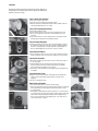
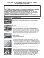
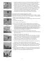
®
Owner’s Operation
& Installation Guide
FLUSHMATE
A Division of Sloan Valve Company
PF1612PA
A Division of Sloan Valve Company
PF1612PA
and
Owner’s Operation and
for
Installation Guide for
503 and 504
Series
PF1612PA
Series
Guía de instalación
y operación del
propietario para las
series PF1612PA
503 y 504
Guide
d’installationetet
Guide d’installation
de fonctionnement
fonctionnementdes
des
séries
503
et
504
séries PF1612PA
Important: Do not return to store where
purchased. Please read the entire manual before
attempting to make any adjustments
or repairs.
WARNING:
• When replacing components on the FLUSHMATE®
Flushometer-Tank System, make certain that the water
supply valve is turned off and the toilet has been
flushed to relieve pressure in the FLUSHMATE® tank.
• USE OF PETROLEUM-BASED LUBRICANTS OR
CORROSIVE CLEANING PRODUCTS CONTAINING
CHLORINE, SUCH AS HOUSEHOLD BLEACH, DROP-IN
BLOCKS OR TABLETS, OR DISINFECTANTS, THAT ARE
APPLIED INSIDE THE CHINA HOLDING TANK WILL
VOID YOUR FLUSHMATE® WARRANTY. The exterior of
the tank and the entire bowl can be cleaned following
the manufacturer’s recommendations or in the same
fashion as any other toilet.
• FLUSHMATE® Flushometer-Tank Systems are
designed to be used with a cold water supply only
and use of a tempered or hot water supply will void
your warranty.
Importante: No lo devuelva a la tienda donde lo
adquirió. Lea todo el manual antes de intentar
realizar cualquier ajuste o reparación.
ADVERTENCIA:
• Al reemplazar componentes del sistema de
flujómetro-tanque FLUSHMATE®, asegúrese de que la
válvula de suministro de aire esté cerrada y el
excusado se haya descargado para liberar la presión
del tanque FLUSHMATE®.
• EL USO DE LUBRICANTES CON BASE DE PETRÓLEO
O PRODUCTOS DE LIMPIEZA CORROSIVOS QUE
CONTENGAN CLORO, TALES COMO EL
BLANQUEADOR CASERO, BLOQUES O TABLETAS
PARA EL AGUA O DESINFECTANTES QUE SE
APLIQUEN DENTRO DEL TANQUE DE DEPÓSITO DE
PORCELANA, ANULARÁN LA GARANTÍA DE SU
FLUSHMATE®. La parte exterior del tanque y toda la
taza se pueden limpiar siguiendo las
recomendaciones del fabricante o del mismo modo
que cualquier otro excusado.
• Los sistemas flujómetro-tanque FLUSHMATE® están
diseñados para usarse con un suministro de agua
fría, y el uso de un suministro de agua templada o
caliente anulará su garantía.
Important : Ne pas retourner le produit au
magasin où vous l’avez acheté. Veuillez lire le
manuel en entier avant de tenter de faire des
réglages ou des réparations.
AVERTISSEMENT :
• Lors du remplacement de composants du système
de réservoir à robinet de chasse FLUSHMATE®,
assurez-vous d’abord de fermer le robinet
d’alimentation et de déclencher ensuite la
chasse afin d'atténuer la pression dans le
réservoir FLUSHMATE®.
• L’UTILISATION, À L’INTÉRIEUR DU RÉSERVOIR DE
RÉTENTION EN PORCELAINE, DE LUBRIFIANTS À
BASE DE PÉTROLE OU DE PRODUITS NETTOYANTS
CORROSIFS QUI CONTIENNENT DU CHLORE,
COMME LES JAVELLISANTS DOMESTIQUES, LES
PASTILLES ET BLOCS NETTOYANTS OU LES
DÉSINFECTANTS, ANNULERA VOTRE GARANTIE
FLUSHMATE®. Vous pouvez nettoyer l’extérieur du
réservoir et la cuvette entière selon les
recommandations du fabricant ou de la même
façon que vous nettoyez toute autre toilette.
• Les systèmes de réservoir à robinet de chasse
FLUSHMATE® sont conçus pour être utilisés
avec une alimentation en eau froide seulement.
L’utilisation d’eau tiède ou chaude annulera
votre garantie.
A Division of Sloan Valve Company
30075 Research Drive
New Hudson, MI 48165
800-533-3460
248-446-5300
www.flushmate.com
Operation
All pressure-assist
pressure-assisttoilets
toiletsget
gettheir
theirenergy
energyfrom
fromthethewater
water
supply
line.
supply
line.
It isIt
is
important
to have
sufficient
pressure
at supply.
the supply.
minimum
important
to have
sufficient
pressure
at the
The The
minimum
line line
pressure
is 25
psi gpf
for 1.0
gpf.is 20 psi and 25 psi for 1.0 gpf.
pressure for
a 1.6
system
Fig. 1
Step
1.Check
CheckFlush
Flush
Cartridge
Step 1.
Cartridge
A. Turn off water
water supply and flflush
toilet.
ush toilet.
B. Pour water onto top of cartridge
cartridge (Fig.
(Fig. 1)
1)and
andturn
turnon
onwater.
water.
C. Watch
ow of
C.
Watch for
for air
air bubbles.
bubbles. Consistent
Consistent flflow
of bubbles
bubbles indicates
indicates cartridge
cartridge needs
needstotobe
be
replaced. No
No bubbles
replaced.
bubbles visible,
visible, move
move on
on to
to Step
Step 4.
4.
Fig. 6
Step
FlushCartridge
Cartridge
Replacement
Step 2.2.Flush
Replacement
Fig. 2
A. Turn off water
water and flflush
the toilet.
toilet.
ush the
B. Use the handle end of pliers
pliers (Fig.
(Fig.2)
2)totounscrew
unscrewthe
thecartridge
cartridgefrom
fromthe
thevessel.
vessel.
C. Drop
C.
Drop in
in new
new cartridge
cartridge and
and screw
screw in
in until
until one
one female
female thread
thread (Fig.
(Fig.3)3)ofofvessel
vessel
is showing.
showing.
is
D. Turn on water. Continue to screw in cartridge slowly, 1/8 to 1/4 turn increments
D. Turn on water. Continue to screw in cartridge slowly, 1/8 to 1/4 turn increments
until water stops running into the bowl and tank pressurizes.
until water stops running into the bowl and tank pressurizes.
Fig. 7
Step 3.3.Actuator
Adjustment
Step
Actuator
Adjustment
A. Start by loosening the setscrew in the center
center of
of the
the actuator.
actuator.Adjust
Adjustthe
theheight
heightofof
the actuator
actuator by screwing
screwing it up or down. There should be a gap
the
gap (Fig.
(Fig.4)4)(about
(aboutthe
the
thickness
between the rod and actuator when gently lifting the rod.
thickness of
of a penny) between
When accomplished
accomplished tighten
tighten the setscrew
setscrew in the center of the actuator.
Step 4. Check Air Inducer
Step 4. Check Air Inducer
Fig. 3
A. Place several drops of water over hole on top of air inducer and flush toilet (Fig. 5).
A. Place
drops of
of air
flush
(Fig. 5).
If dropseveral
is vacuumed
in,water
moveover
ontohole
stepon
6.top
If not,
airinducer
inducerand
needs
to toilet
be cleaned.
If drop is vacuumed in, move onto step 6. If not, air inducer needs to be cleaned.
Step 5. Clean Air Inducer
Fig. 8
A.
Turn5.
offClean
water and
toilet. Unscrew the cap of the air inducer (the smaller of
Step
Airflush
Inducer
the two
caps) (Fig.
A. Turn
off water
and fl6).
ush toilet. Unscrew the cap of the air inducer (the smaller of
the two
caps) (Fig.
B. Pull
the duckbill
out6).from the cap and clean it by gently squeezing it (Fig. 7)
B. between
Pull the duckbill
out from
theacap
clean itInspect
by gently
(Fig. 7)
your fingers
under
flowand
of water.
the squeezing
lips of the itduckbill.
fingers the
under
a flowneeds
of water.
the lips of the duckbill.
Ifbetween
they areyour
deformed,
duckbill
to beInspect
replaced.
If they are deformed,
duckbill
needs
be replaced.
C. Reassemble,
insert thetheduct
bill into
the to
housing
(Fig. 8) body and reinstall the cap
C. Reassemble,
to hand tight.insert the duct bill into the housing (Fig. 8) body and reinstall the cap
to hand tight.
Step 6. Clean Inlet Screen
Fig. 4
A.
Clean6.the
inlet screen
by turning off the water supply, disconnecting the water
Step
Clean
Inlet Screen
supplythe
lineinlet
fromscreen
the supply
shankoffand
the screen
with a paper
A. Clean
by turning
theremoving
water supply,
disconnecting
the water
clip
(Fig.line
9).from the supply shank and removing the screen with a paper
supply
B. Clean
screen
clip (Fig.
9). (Fig. 10) and replace.
B. Clean screen (Fig. 10) and replace.
Fig. 9
Other Points to Remember
Fig. 5
1. Pressure-assist toilets get their energy from the water supply.
Other Points to Remember
2.
pressure-assist
toilets
their
energy
from
water
supply line. It is important
1. All
Pressure-assist
toilets
getget
their
energy
from
thethe
water
supply.
sufficient pressure
at their
the supply.
minimum
linesupply
pressure
1.6 gpf
2. to
Allhave
pressure-assist
toilets get
energyThe
from
the water
line. for
It isaimportant
system is 20 psi and 25 psi for 1.0 gpf.
to have sufficient pressure at the supply. The minimum line pressure is 25 psi
3. Aforblocked
bowl
or drain will affect the fixture’s performance. To check for this, pour
a 1.0 gpf
system.
to 3 gallons
bowl.
the bowl
accumulatesTowater
it, this,
this would
3. A2 blocked
bowloforwater
draininto
will the
affect
the Iffixture’s
performance.
checkinfor
pour
indicate
that something
is blocking
bowl/drain.
If you needwater
additional
help,would
bowl accumulates
in it, this
2 to 3 gallons
of water into
the bowl.theIf the
please
the manufacturer
of the
the bowl/drain.
flushing system,
do aadditional
word search
indicatecontact
that something
is blocking
If youorneed
help,on
“pressure-assist toilets” on the web.
please contact the manufacturer of the flushing system, or do a word search on
“pressure-assist toilets” on the web.
-2-
Fig. 10
Operación
Todos los
los excusados
excusadosasistidos
asistidospor
porpresión
presiónobtienen
obtienensusuenergía
energía
tubería de
dede
la la
tubería
suministro
de de
agua.
EsEs
importante
ciente en
de suministro
agua.
importantetener
tenerpresión
presiónsufi
suficiente
enelelsuministro.
La
presión mínima
de mínima
la tubería
agua para
un sistema
25 psi de
para un
suministro.
La presión
de de
la tubería
de agua
para undesistema
dispositivo
de20
1.0psi
gpf.
1.6 gpf es de
y de 25 psi para un dispositivo de 1.0 gpf.
Fig. 1
Paso
Compruebe
el cartucho
de descarga
Paso 1.1.Compruebe
el cartucho
de descarga
A. Corte el suministro de agua
agua yy descargue
descargue elel excusado.
excusado.
B. Vierta agua encima del cartucho
cartucho (Fig.
(Fig. 1)
1) yyabra
abraelelagua.
agua.
C. Vea
ujo constante
C.
Vea sisi hay
hay burbujas
burbujas de
de aire.
aire.Un
Unflflujo
constantede
deburbujas
burbujasindica
indicaque
queelelcartucho
cartucho
debe sustituirse.
sustituirse. Si
Si no
debe
no hay
hay burbujas
burbujas visibles,
visibles, vaya
vaya al
al Paso
Paso 4.
4.
Fig. 6
Paso
Repuesto
cartucho
de descarga
Paso 2.2.Repuesto
deldel
cartucho
de descarga
Fig. 2
A. Cierre el agua y descargue
descargue el
el excusado.
excusado.
B. Use el extremo del mango de las
las pinzas
pinzas (Fig.
(Fig. 2)
2) para
paradesatornillar
desatornillarelelcartucho
cartucho
de la vasija.
de
C. Deje
C.
Deje caer
caer un
un nuevo
nuevo cartucho
cartucho yy atorníllelo
atorníllelo hasta
hasta que
que se
se esté
estéviendo
viendouna
unavuelta
vueltade
de
rosca hembra
hembra (Fig.
(Fig. 3)
rosca
3) de
de la
la vasija.
vasija.
D. Abra el agua. Siga atornillando el cartucho lentamente, en incrementos de 1/8 a
D. Abra el agua. Siga atornillando el cartucho lentamente, en incrementos de 1/8 a
1/4 de vuelta hasta que el agua deje de correr al lavabo y el tanque se presurice.
1/4 de vuelta hasta que el agua deje de correr al lavabo y el tanque se presurice.
Fig. 7
Paso 3.3.Ajuste
deldel
accionador
Paso
Ajuste
accionador
ojando el tornillo de fifijación
jación del centro del
A. Empiece afl
aflojando
del accionador.
accionador. Ajuste
Ajuste lala altura
altura
del
haber un
un huelgo
huelgo (Fig.
(Fig.4)4)
del accionador
accionador atornillando
atornillando para que suba o baje. Debe haber
(más
el vástago
vástago yy elel accionador
accionador
(más o menos el grosor de una moneda pequeña) entre el
cuando
apriete el
el tornillo
tornillo de
de
cuando se
se levanta
levanta suavemente
suavemente el
el vástago.
vástago. Cuando
Cuando termine,
termine, apriete
fijación
fijación del
del centro
centro del
del accionador.
accionador.
Paso 4. Compruebe el inductor de aire
Fig. 3
Paso
4. Compruebe
inductor
de aire
A.
Coloque
varias gotas deel
agua
sobre el orificio
que está en la parte superior del
A. Coloque
de agua el
sobre
el orificio
la parte
superiorpor
del
inductor varias
de aire,gotas
y descargue
excusado
(Fig.que
5). está
Si la en
caída
se absorbe
inductor vaya
de aire,
y descargue
excusado
(Fig.limpiar
5). Si laelcaída
se absorbe
presión,
al Paso
6. Si no,elserá
necesario
inductor
de aire. por
presión, vaya al Paso 6. Si no, será necesario limpiar el inductor de aire.
Fig. 8
Paso 5. Limpie el inductor de aire
Fig. 4
A.
Corte5.elLimpie
agua y descargue
el excusado.
Desatornille la tapa del inductor de aire (la
Paso
el inductor
de aire
más pequeña
las dos tapas)
(Fig. 6).Desatornille la tapa del inductor de aire (la
A. Corte
el agua ydedescargue
el excusado.
B. Saque
el pico de pato
deltapas)
tapón (Fig.
y límpielo
más pequeña
las dos
6). oprimiéndolo suavemente (Fig. 7) entre
dedos
bajode
unpato
chorro
agua.
Inspeccione
los labiossuavemente
del pico de (Fig.
pato.7)Sientre
están
B. los
Saque
el pico
del de
tapón
y límpielo
oprimiéndolo
deformados,
debe
reemplazar
el pico
de pato. los labios del pico de pato. Si están
los dedos bajo
un chorro
de agua.
Inspeccione
deformados,
debe
reemplazar
C. Vuelva
a armar,
inserte
el pico el
depico
patodeenpato.
el cuerpo de la carcasa (Fig. 8) y vuelva
C. Vuelva
a armar,
el pico
de con
patolaenmano.
el cuerpo de la carcasa (Fig. 8) y vuelva
a instalar
la tapainserte
apretando
sólo
a instalar la tapa apretando sólo con la mano.
Paso 6. Limpie la pantalla de admisión
Fig. 9
A. Limpie la pantalla de admisión cerrando el suministro de agua, desconectando el
Paso
6. Limpie la pantalla de admisión
tubo de suministro de agua del vástago de suministro y retirando la pantalla con un
A. Limpie la pantalla de admisión cerrando el suministro de agua, desconectando el
clip para papeles (Fig. 9).
tubo de suministro de agua del vástago de suministro y retirando la pantalla con un
B. Limpie
la papeles
pantalla (Fig.
(Fig.9).
10) y reemplácela.
clip para
B. Limpie la pantalla (Fig. 10) y reemplácela.
Otros puntos que debe recordar
Fig. 5
1. Los excusados asistidos por presión obtienen su energía del suministro de agua.
Otros puntos que debe recordar
2. Todos los excusados asistidos por presión obtienen su energía de la tubería de
1. Los excusados asistidos por presión obtienen su energía del suministro de agua.
suministro de agua. Es importante tener presión suficiente en el suministro. La
2. Todos
excusados
poragua
presión
su energía
de laestubería
presiónlosmínima
de laasistidos
tubería de
paraobtienen
un sistema
de 1.6 gpf
de 20 de
psi y de
suministro
Es importante
tener presión suficiente en el suministro. La
25
psi parade
unagua.
dispositivo
de 1.0 gpf.
presión mínima de la tubería de agua para un sistema de 25 psi para un dispositivo
3. Una taza o drenaje bloqueados afectará el desempeño del dispositivo.
de 1.0 gpf.
Para comprobar esto, vierta 2 ó 3 galones de agua en la taza. Si la taza acumula
3. Una taza o drenaje bloqueados afectará el desempeño del dispositivo.
agua en su interior, esto indicaría que algo está bloqueando la taza o el drenaje.
Para
comprobar
esto, vierta
2 ó 3 galones
agua en ladel
taza.
Si la taza
acumula o
Si
necesita
más ayuda,
comuníquese
con eldefabricante
sistema
de descarga,
indicaría
que“pressure-assist
algo está bloqueando
o el drenaje.
agua una
en subúsqueda
interior, esto
haga
de las
palabras
toilets”laentaza
la Web.
Si necesita más ayuda, comuníquese con el fabricante del sistema de descarga, o
haga una búsqueda de las palabras “pressure-assist toilets” en la Web.
-3-
Fig. 10
Fonctionnement
Toutes les toilettes à pression
pression tirent
tirent leur
leur énergie
énergie du
du tuyau
tuyaud’alimentation.
d’alimentation.
Il est donc important d’avoir
samment de
d’avoir suffi
suffisamment
de pression
pression d’alimentation.
d’alimentation.La
La
pression du tuyau d’alimentation pour
moins
psi pour 1
pour un
un système
système àà d’au
1,6 gpc
doit25être
gpc.
d’au moins 20 psi, et d’au moins 25 psi pour 1 gpc.
Fig. 1
Étape
Vérification
la cartouche
de chasse
Étape 1.1.Vérifi
cation de de
la cartouche
de chasse
A. Fermez lele robinet
robinetd’alimentation
d’alimentationeneneau,
eau,
puis
déclenchez
la chasse.
puis
déclenchez
la chasse.
cartouche
(fig.(fig.
1), 1),
puispuis
ouvrez
le robinet
B. Versez
Versez de
del’eau
l’eausur
surleledessus
dessusdedela la
cartouche
ouvrez
le robinet
d’alimentation en
d’alimentation
eneau.
eau.
C. Vérifi
ez sisides
UnUn
écoulement
de de
bulles
constant
C.
Vérifiez
desbulles
bullesd’air
d’airseseforment.
forment.
écoulement
bulles
constant
indique que
Si Si
aucune
bulle
n’apparaît,
indique
que lalacartouche
cartouchedoit
doitêtre
êtreremplacée.
remplacée.
aucune
bulle
n’apparaît,
passez àà l’étape
passez
l’étape4.4.
Fig. 6
Étape
Remplacement
decartouche
la cartouche
de chasse
Étape 2.2.Remplacement
de la
de chasse
Fig. 2
A.
Fermez lele robinet
robinetd’alimentation
d’alimentationeneneau,
eau,
puis
déclenchez
la chasse.
A. Fermez
puis
déclenchez
la chasse.
(fig.
2) pour
dévisser
la cartouche
B. Utilisez
Utilisez l’extrémité
l’extrémitédes
desmanches
manchesd’une
d'unepince
pince
(fig.
2) pour
dévisser
la cartouche
et la retirer
retirer du
durécipient.
récipient.
C. Insérez
jusqu’à
ce ce
qu’un
filetfilet
femelle
C.
Insérez lalanouvelle
nouvellecartouche,
cartouche,puis
puisvissez-la
vissez-la
jusqu’à
qu’un
femelle
(fig. 3) du
(fig.
du récipient
récipientapparaisse.
apparaisse.
D. Ouvrez
Continuez
à visser
lentement
la la
D.
Ouvrez lele robinet
robinetd’alimentation
d’alimentationeneneau.
eau.
Continuez
à visser
lentement
cartouche en
dede
tour
à laà fois,
jusqu’à
ce que
cartouche
en faisant
faisantun
unhuitième
huitièmeououununquart
quart
tour
la fois,
jusqu'à
ce que
l’eau arrête
et et
queque
la pression
soitsoit
rétablie
dansdans
l'eau
arrête de
des’écouler
s'écoulerdans
danslalacuvette
cuvette
la pression
rétablie
le réservoir.
le
réservoir.
Fig. 7
Étape
Réglage
l’actionneur
Étape 3.3.Réglage
de de
l’actionneur
Fig. 3
A.
Desserrez d’abord
d’abordlalavis
visdedepression
pressionauau
milieu
l’actionneur.
Réglez
A. Desserrez
milieu
dede
l’actionneur.
Réglez
la la
hauteur
de l’actionneur
l'actionneuren
enlelefaisant
faisantpivoter
pivoter
vers
le haut
le bas.
Il doit
hauteur de
vers
le haut
ou ou
versvers
le bas.
Il doit
y y
avoir
un espace
espace (fi(fig.
(environdedel’épaisseur
l’épaisseur
d’une
pièce
d’un
cent)
entre
avoir un
g. 4)4)(environ
d’une
pièce
d’un
cent)
entre
le le
levier et l’actionneur quand on lève doucement le levier. Une fois le réglage
levier et l’actionneur quand on lève doucement le levier. Une fois le réglage
terminé, resserrez la vis de pression au milieu de l’actionneur.
terminé, resserrez la vis de pression au milieu de l’actionneur.
Fig. 8
Étape 4. Vérification de la soupape d’entrée d’air
Étape
Vérification
la soupape
d’air
A.
Versez4.plusieurs
gouttesde
d’eau
dans le troud’entrée
sur le dessus
de la soupape
A. Versez
plusieurs
gouttes
d’eau dans
le trou (fig.
sur le5).dessus
la soupape
d’entrée
d’air, puis
déclenchez
la chasse
Si les de
gouttes
sont aspirées,
passez
l’étape
Sinon, vousla devez
la les
soupape
d’air.
d’entréeàd’air,
puis6.déclenchez
chassenettoyer
(fig. 5). Si
gouttesd’entrée
sont aspirées,
passez à l’étape 6. Sinon, vous devez nettoyer la soupape d’entrée d’air.
Étape 5. Nettoyage de la soupape d’entrée d’air
Fig. 4
A. Fermez le robinet d’alimentation en eau, puis déclenchez la chasse.
Étape
5. Nettoyage de la soupape d’entrée d’air
Dévissez le capuchon de la soupape d’entrée d’air (le plus petit des deux
A. Fermez
le robinet
d’alimentation en eau, puis déclenchez la chasse.
capuchons)
(fig. 6).
Dévissez le capuchon de la soupape d’entrée d’air (le plus petit des deux
B. Retirez
le bec
capuchons)
(fig.de6).canard du capuchon, puis nettoyez-le en le pressant
délicatement entre vos doigts (fig. 7) sous l’eau courante. Examinez les
B. Retirez le bec de canard du capuchon, puis nettoyez-le en le pressant
lèvres du bec de canard. Si elles sont déformées, vous devez remplacer le
délicatement entre vos doigts (fig. 7) sous l’eau courante. Examinez les
bec de canard.
lèvres du bec de canard. Si elles sont déformées, vous devez remplacer le
C. Montez
la soupape à nouveau en insérant le bec de canard dans le corps du
bec de canard.
boîtier (fig.
8), puisàremettez
vissez-le
fermement
à la main.
C. Montez
la soupape
nouveau le
encapuchon
insérant leetbec
de canard
dans le corps
du
Fig. 9
boîtier (fig. 8), puis remettez le capuchon et vissez-le fermement à la main.
Étape 6. Nettoyage de la grille d’entrée
Fig. 5
A. Pour nettoyer la grille d’entrée, fermez le robinet d’alimentation en eau,
Étape
6. Nettoyage
de la grille en
d’entrée
débranchez
le tuyau d’alimentation
eau de la tige d’alimentation, puis retirez
A. Pour
nettoyer
la grille
la grille
à l’aide
d’un d’entrée,
trombonefermez
(fig. 9).le robinet d’alimentation en eau,
débranchez
le tuyau
en eau deen
la place.
tige d’alimentation, puis retirez
B. Nettoyez
la grille
(fig.d’alimentation
10), puis remettez-la
la grille à l’aide d’un trombone (fig. 9).
B. Nettoyezpoints
la grille (fiàg. ne
10), pas
puis remettez-la
Autres
oublier en place.
1. Toutes les toilettes à pression tirent leur énergie du tuyau d’alimentation.
Autres
à ne
pas oublier
2.
Toutes points
les toilettes
à pression
tirent leur énergie du tuyau d’alimentation. Il est
1. Toutes
les toilettes
à pression
tirent leurde
énergie
du tuyau
d’alimentation.
donc important
d’avoir
suffisamment
pression
d’alimentation.
La pression du
2. Toutes
les toilettes à pression
leur énergie
du doit
tuyau
d’alimentation.
Il est
tuyau d’alimentation
pour untirent
système
à 1,6 gpc
être
d’au moins 20
psi, et
d’au
25 psi
poursuffi
1 gpc.
doncmoins
important
d’avoir
samment de pression d’alimentation. La pression du
tuyaucuvette
d’alimentation
undrain
système
êtreinfluera
d’au moins
psi, et d’au moins
3. Une
bloquéepour
ou un
bloqué
sur 20
la performance
de 25 psi
pour 1 gpc.sanitaire. Pour vérifier s’il y a une obstruction, versez 2 ou 3 gallons
l’appareil
3. Une
bloquée
ou Si
unl’eau
drains’accumule
bloqué influera
surlalacuvette,
performance
de
d’eaucuvette
dans la
cuvette.
dans
cela signifie
que la
l’appareilousanitaire.
vérifier Si
s’ilvous
y a une
obstruction,
2 ousupplémentaire,
3 gallons
cuvette
le drain Pour
est bloqué.
désirez
obtenirversez
de l’aide
veuillez
contacter
le fabricant
du systèmedans
de chasse
d'eau
faitese que
une la
d’eau dans
la cuvette.
Si l’eau s’accumule
la cuvette,
celaousignifi
recherche
Internet
à l’aideSides
mots
« toilettes
».
cuvette ou sur
le drain
est bloqué.
vous
désirez
obteniràdepression
l’aide supplémentaire,
veuillez contacter le fabricant du système de chasse d’eau ou faites une
recherche sur Internet à l’aide des mots « toilettes à pression »
-4-
Fig. 10
Installation
Instalación
Installation
Please follow the toilet manufacturer’s installations
instruction for installing the fixture. Note that the toilet
requires a minimum water supply line pressure of
25 psi for a 1 gpf fixture. Before attaching, you should
always flush the water supply lines.
Siga las instrucciones de instalación del fabricante del
excusado para instalarlo. Observe que el excusado
requiere un suministro de presión de la línea de agua
para un dispositivo de 25 psi para un dispositivo de 1
gpf. Antes de instalarlo, siempre debe purgar las líneas
de suministro de agua.
Veuillez installer l’appareil sanitaire en suivant les
instructions d’installation du fabricant de la toilette.
Prenez note que la pression du tuyau d’alimentation
en eau de la toilette doit être d’au moins pour
un appareil de et d’au moins pour un appareil de 1
gpc. Vous devez toujours évacuer l’eau des tuyaux
d’alimentation en eau avant de les raccorder.
After completing the installation, you are required to
adjust the Cartridge Actuator (F). To adjust, make sure
the water is turned on and the vessel is completely
charged. The Actuator needs to be set at the proper
clearance, 1/8” from either the Flush Rod or push
button. To make this adjustment, hold the Actuator
while loosening the Phillips setscrew in the center of
the Actuator, and rotate the Actuator up
(counterclockwise) or down (clockwise) until the proper
clearance is obtained. See Figure 1 for clearance
required for flush-handle fixture. Tighten setscrew after
adjusting the Actuator.
Additional notes:
• You may be required to initially flush the toilet a few
times to properly charge the system.
• Should your fixture develop a leak between the tank
and bowl, please refer to the fixture manufacturer’s
installation instructions.
Después de finalizar la instalación, debe de ajustar el
Accionador del Cartucho (F). Para ajustarlo, asegúrese
de que el agua esté activada y la vasija esté totalmente
cargada. El accionador tiene que ajustarse al huelgo
correspondiente, a 1/8” de la varilla de descarga o del
botón. Para hacer este ajuste, sostenga el accionador
mientras afloja el tornillo de fijación de cruz del centro
del accionador y gire el accionador hacia arriba (en
sentido contrario al de las manecillas del reloj) o hacia
abajo (en el sentido de las manecillas del reloj) hasta
obtener el huelgo correcto. Véase la Figura 1 para
conocer el huelgo necesario para el dispositivo de
manija de descarga. Apriete el tornillo de fijación
después de ajustar el accionador.
Notas adicionales:
• Es posible que sea necesario que primero descargue
el excusado varias veces para cargar
adecuadamente el sistema.
• Si su dispositivo desarrolla una fuga entre el tanque
y la taza, consulte las instrucciones de instalación
del fabricante del dispositivo.
Une fois l’installation terminée, vous devrez régler
l’actionneur de la cartouche (F). Pour le régler,
assurez-vous d’avoir ouvert l’alimentation en eau et
vérifiez que le récipient est complètement rempli.
Pour que l’actionneur soit correctement réglé,
l’espacement entre celui-ci et le levier de
déclenchement ou le bouton-poussoir doit être de
1/8 po. Pour effectuer ce réglage, tenez l’actionneur
tout en desserrant la vis de pression Phillips au
centre de l’actionneur, puis faites pivoter l’actionneur
vers le haut (sens antihoraire) ou vers le bas (sens
horaire) pour obtenir l’espacement adéquat. La figure
1 montre l’espacement nécessaire pour les appareils
à manette de chasse. Serrez la vis de pression une
fois le réglage de l’actionneur terminé.
Autres remarques:
• Initialement, il est possible que vous deviez
déclencher la chasse de la toilette à plusieurs
reprises afin de remplir correctement le système.
• En cas de fuite entre le réservoir et la cuvette,
veuillez consulter les instructions d’installation du
fabricant de l’appareil sanitaire.
(F)
(H)
❸
(I)
❹
(B)
(A)
(C)
❷
❶
(D)
(E)
(G)
FLUSHMATE® 504
FLUSHMATE® 504
FLUSHMATE® 504
Function: Less than 1.0 gpf/3.8 Lpf
Installation Requirements: min. 25 psi static water
pressure*
List of Components for 503 and 504 Series:
1. Lower Supply Group w/Hose BL100504-3
(A) Supply Shank w/inlet screen
(B) Pressure Regulator w/Back Check
(C) Relief Valve
2. Upper Supply Group BU100505
(D) Air Inducer Cap w/duckbill
(E) Vacuum Breaker
3. Flush Valve Cartridge Assembly
(F) Actuator w/setscrew
4. FLUSHMATE® Tank
(G) Discharge Extension w/Drain
(H) Name Plate w/Serial Number
(I) Flush Rod
Función: Menos de 1.0 gpf/3.8 Lpf
Requisitos de instalación: mín. presión de agua estática
de 25 psi*
Lista de componentes para las series 503 y 504:
1. Grupo inferior de suministro con manguera
BL100504-3
(A) Vástago de suministro con pantalla de admisión
(B) Regulador de presión con supresión trasera
(C) Válvula de seguridad
2. Grupo de suministro superior BU100505
(D) Tapa inductora de aire con pico de pato
(E) Divisor de vacío
3. Conjunto del cartucho de la válvula de
descarga
(F) Accionador con tornillo de fijación
4. Tanque FLUSHMATE®
(G) Extensión de descarga con drenaje
(H) Placa de nombre con número de serie
(I) Varilla de descarga
Fonction : moins de 1,0 gpc/3,8 lpc
Exigences d’installation : 25 psi de pression d’eau
statique min.*
Liste des composants des séries 503 et 504 :
1. Groupe d’alimentation inférieur avec flexible
BL100504-3
(A) Tige d’alimentation avec grille d’entrée
(B) Régulateur de pression avec dispositif
antirefoulement
(C) Soupape de décharge
2. Groupe d’alimentation supérieur BU100505
(D) Soupape d’entrée d’air avec bec de canard
(E) Casse-vide
3. Cartouche du robinet de chasse
(F) Actionneur avec vis de pression
4. Réservoir FLUSHMATE®
(G) Rallonge d’évacuation avec drain
(H) Plaque d’identification avec numéro de série
(I) Levier de déclenchement
*max. 125 psi
*máx. 125 psi
*125 psi max.
-5-
Winterizing
Preparación para el invierno
Préparation pour l’hiver
1. Turn off the water supply valve and flush the toilet to
relieve the pressure.
2. Place a bucket under the lower Supply Shank (A) and
disconnect the water supply line, allowing the water
to drain into the bucket.
3. Push down on the Actuator and pull it up
momentarily to allow air into the vessel.
4. Follow the fixture manufacturer’s instructions for
winterizing the bowl.
5. Do not put antifreeze or any other chemical agents in
the china holding tank or in the FLUSHMATE® Tank.
1. Cierre la válvula de suministro de agua y descargue
el excusado para liberar la presión.
2. Coloque una cubeta bajo el vástago de suministro (A)
y desconecte el tubo de suministro de agua, para
que ésta se drene en la cubeta.
3. Empuje el accionador hacia abajo y tire de él
momentáneamente para permitir que entre aire en
la vasija.
4. Siga las instrucciones del fabricante del aparato para
preparar la taza para el invierno.
5. No ponga anticongelante ni ningún otro agente
químico en el tanque de depósito de porcelana o en
el tanque de FLUSHMATE®.
1. Fermez le robinet d’alimentation en eau, puis
déclenchez la chasse pour atténuer la pression.
2. Placez un seau sous la partie inférieure de la tige
d’alimentation (A), puis débranchez le tuyau
d’alimentation en eau et laissez l’eau s'écouler
dans le seau.
3. Appuyez sur l’actionneur, puis tirez-le vers le haut
et attendez quelques instants pour laisser l'air
pénétrer dans le récipient.
4. Suivez les instructions du fabricant de l'appareil
sanitaire quant à la préparation pour l’hiver de
la cuvette.
5. Ne versez pas d’antigel ni d’autres agents
chimiques dans le réservoir de rétention en
porcelaine ni dans le réservoir FLUSHMATE®.
Points to Remember
• When replacing components on the FLUSHMATE®
Flushometer-Tank System, make certain that the
water supply valve is turned off and the toilet
has been flushed to relieve pressure in the
FLUSHMATE® tank.
• USE OF PETROLEUM-BASED LUBRICANTS OR
CORROSIVE CLEANING PRODUCTS CONTAINING
CHLORINE, SUCH AS HOUSEHOLD BLEACH, DROP-IN
BLOCKS OR TABLETS, OR DISINFECTANTS THAT ARE
APPLIED INSIDE THE CHINA HOLDING TANK WILL
VOID YOUR FLUSHMATE® WARRANTY.
• FLUSHMATE® Flushometer-Tank Systems are
designed to be used with cold water.
• The Flush Valve Cartridge can be removed by
inserting the handles of a pair of pliers into the top
of the Flush Valve Cartridge and turning
counterclockwise.
• A small amount of water may be present in the
bottom of the china holding tank. The potential for
odor can be eliminated by adding a cup of white
vinegar to the china holding tank. The white vinegar
will act as a natural disinfectant.
• Your water pressure is adequate if your water supply
line will yield one or more gallons of water within
thirty (30) seconds.
• Replacement parts are readily available by
contacting Consumer Services at 800-533-3460
or by visiting the “Where to Buy” section of our
website, www.flushmate.com, or purchase online
at www.eflushmate.com.
If you would like additional information or require
technical assistance, please contact FLUSHMATE®
Consumer Services at 800-533-3460, or visit our
website, www.flushmate.com. For faster service, please
be prepared to provide the serial number and date of
installation of your FLUSHMATE® system.
© 2009 Wolseley
Puntos que debe recordar
• Al reemplazar componentes del sistema de
flujómetro-tanque FLUSHMATE®, asegúrese de que
la válvula de suministro de aire esté cerrada y el
excusado se haya descargado para liberar la presión
del tanque FLUSHMATE®
• EL USO DE LUBRICANTES CON BASE DE PETRÓLEO
O PRODUCTOS DE LIMPIEZA CORROSIVOS QUE
CONTENGAN CLORO, TALES COMO EL
BLANQUEADOR CASERO, BLOQUES O TABLETAS
PARA EL AGUA O DESINFECTANTES QUE SE
APLIQUEN DENTRO DEL TANQUE DE DEPÓSITO
DE PORCELANA, ANULARÁN LA GARANTÍA DE
SU FLUSHMATE®.
• Los sistemas de flujómetro-tanque FLUSHMATE®
están diseñados para usarse con agua fría.
• El cartucho de la válvula de descarga se puede quitar
insertando los mangos de unas pinzas en la parte
superior del cartucho de la válvula de descarga y
girando en sentido contrario al de las manecillas
del reloj.
• Puede estar presente una pequeña cantidad de agua
en el fondo del tanque de depósito de porcelana. El
potencial de malos olores puede eliminarse
añadiendo una taza de vinagre blanco al tanque de
almacenamiento de porcelana. El vinagre blanco
actuará como un desinfectante natural.
• Su presión de agua es adecuada si su línea de
suministro rinde uno o más galones de agua en un
lapso de treinta (30) segundos.
• Hay piezas de repuesto fácilmente disponibles
comunicándose con Servicios al Cliente al 800-5333460 o visitando la sección “Dónde comprar” de
nuestro sitio Web www.flushmate.com, o compre en
línea en www.eflushmate.com.
Si desea información adicional o requiere de asistencia
técnica, comuníquese con Servicios al Cliente de
FLUSHMATE® al 800-533-3460, o visite nuestro sitio
Web, www.flushmate.com. Para obtener un servicio más
rápido, debe estar preparado para dar el número de
serie y fecha de instalación de su sistema FLUSHMATE®.
Distributed Exclusively by Ferguson and Wolseley Canada
Points à ne pas oublier
• Lors du remplacement de composants du
système de réservoir à robinet de chasse
FLUSHMATE®, assurez-vous d’abord de fermer le
robinet d’alimentation et de déclencher ensuite
la chasse afin d'atténuer la pression dans le
réservoir FLUSHMATE®.
• L’UTILISATION, À L’INTÉRIEUR DU RÉSERVOIR DE
RÉTENTION EN PORCELAINE, DE LUBRIFIANTS À
BASE DE PÉTROLE OU DE PRODUITS NETTOYANTS
CORROSIFS QUI CONTIENNENT DU CHLORE, COMME
LES JAVELLISANTS DOMESTIQUES, LES PASTILLES
ET BLOCS NETTOYANTS OU LES DÉSINFECTANTS,
ANNULERA VOTRE GARANTIE FLUSHMATE®.
• Les systèmes de réservoir à robinet de chasse
FLUSHMATE® sont conçus pour être utilisés avec de
l’eau froide.
• Pour retirer la cartouche du robinet de chasse,
insérez les manches d’une paire de pinces dans le
haut de la cartouche du robinet de chasse, puis
tournez dans le sens antihoraire.
• Il est possible qu'une petite quantité d'eau reste
dans le fond du réservoir de rétention en porcelaine.
Vous pouvez éliminer les risques d’odeur en versant
une tasse de vinaigre blanc dans le réservoir de
rétention en porcelaine. Le vinaigre blanc agira
comme un désinfectant naturel.
• Votre pression d’eau est suffisante si le tuyau
d’alimentation en eau produit un gallon d’eau ou
plus en trente (30) secondes.
• Vous pouvez obtenir des pièces de rechange en
contactant le service à la clientèle au 800-5333460, en visitant la section « Where to Buy » (où
acheter) de notre site Web, www.flushmate.com, ou
en les achetant en ligne au www.eflushmate.com.
Si vous désirez de plus amples renseignements ou
avez besoin d’assistance technique, veuillez
communiquer avec le service à la clientèle de
FLUSHMATE® au 800-533-3460 ou visitez notre site
Web, www.flushmate.com. Pour obtenir un service plus
rapide, veuillez avoir en main le numéro de série et la
date d’installation de votre système FLUSHMATE®.
0061 08/10
®
Tank Service Manual
FLUSHMATE
Flushometer - Tank System
504
PF1612PA
FLUSHMATE® 503 AND 504 SERIES
q
static water pressure*
p
PF1612 Series
FLUSHMATE® 504
Function: Less than 1.0 gpf/3.8 Lpf
Installation Requirements: min. 25 psi
static water pressure*
*max. 125 psi
(F)
(H)
1. Lower Supply Group w/Hose
BL100504-3
(A) Supply Shank
(B) Pressure Regulator w/Back Check
(C) Relief Valve
❸
2. Upper Supply Group BU100505
(D) Air Inducer
(E) Vacuum Breaker
❹
(B)
List of Components for
503 andSeries
504 Series:
PF1612
(C)
❷
❶
(I)
(E)
(A)
(G)
(D)
3. Flush Valve Cartridge Assembly
C-100500
(F) Actuator w/setscrew
4. FLUSHMATE® Tank
(G) Discharge Extension w/Drain
(H) Name Plate w/Serial Number
(I) Flush Rod
INSTALLATION
Please follow the toilet manufacturer’s installations instruction for installing the fixture. Note that the toilet
requires a minimum water supply line pressure of 20 psi for a 1.6 gpf and 25 psi for a 1 gpf fixture. Before
attaching, you should always flush the water supply lines.
After completing the installation, you are required to adjust the Cartridge Actuator (F). To adjust, make sure the
water is turned on and the vessel is completely charged. The Actuator needs to be set at the proper clearance,
1/8” from either the Flush Rod or push button. To make this adjustment, hold the Actuator while loosening the
Phillips setscrew in the center of the Actuator, and rotate the Actuator up (counterclockwise) or down (clockwise)
until the proper clearance is obtained. See Figure 1 for clearance required for flush-handle fixture. Tighten
setscrew after adjusting the Actuator.
Additional notes:
• Should your toilet continuously run-on after installing, refer to section #1 under Troubleshooting.
• You may be required to initially flush the toilet a few times to properly charge the system.
• Should your fixture develop a leak between the tank and bowl, please refer to the fixture manufacturer’s
installation instructions.
-2-
PLEASE READ THE ENTIRE MANUAL BEFORE ATTEMPTING TO MAKE
ANY ADJUSTMENTS OR REPAIRS.
WARNING:
• When replacing components on the FLUSHMATE® Flushometer-Tank System, make certain that the
water supply valve is turned off and the toilet has been flushed to relieve pressure in the
FLUSHMATE® tank.
• USE OF PETROLEUM-BASED LUBRICANTS OR CORROSIVE CLEANING PRODUCTS CONTAINING
CHLORINE, SUCH AS HOUSEHOLD BLEACH, DROP-IN BLOCKS OR TABLETS, OR
DISINFECTANTS, THAT ARE APPLIED INSIDE THE CHINA HOLDING TANK WILL VOID YOUR
FLUSHMATE® WARRANTY. The exterior of the tank and the entire bowl can be cleaned following
the manufacturer’s recommendations or in the same fashion as any other toilet.
• FLUSHMATE® Flushometer-Tank Systems are designed to be used with a cold water supply only
and use of a tempered or hot water supply will void your warranty.
TROUBLESHOOTING
A) Condition: Water runs and will not shut off
Figure 1
A run-on condition may be caused by insufficient water pressure, an improperly
adjusted Flush Valve Cartridge, or a clogged inlet screen. Refer to “Installation
Requirements” for recommended minimum pressure. (See “Points to Remember” for
a simple method to determine whether your water pressure is adequate). Check water
pressure, marginal pressure can cause any of these conditions. If sufficient water
pressure has been verified and the toilet continues to run-on, the following steps may
be required:
1. Make sure the water supply valve is fully open.
Figure 2
2. Check the Actuator adjustment. The Flush Rod (I) or push button should not
interfere with the Actuator. The proper clearance should be approximately 1/8”
when the push button or flush-handle is stationary. On push button type fixtures,
loosen the setscrew on the Actuator (see F on the component list) and rotate the
Actuator up (counterclockwise) or down (clockwise) until the proper clearance is
obtained. For flush-handle fixtures, observe the clearance. (See Figure 1) If
necessary, adjust the Actuator to allow for proper clearance. When proper
clearance is obtained, tighten the setscrew.
3. Check Inlet Screen
a. Turn off the water supply valve.
b. Flush the toilet to relieve the pressure.
Figure 3
c. Disconnect the water supply line from the Supply Shank (A). (See Figure 6)
d. Examine the inlet screen and remove anything that may be blocking the flow of
water into the FLUSHMATE® tank. The inlet screen can be removed by inserting
a small pointed object (such as a large paperclip or the blade of a penknife) into
the lower Supply Shank and working the inlet screen loose. (See Figures 7a, 7b,
7c) Reinstall the inlet screen by pushing it upward into the Supply Shank with
your fingertip. (See Figure 7d)
Figure 4
e. Reattach water supply line and fully open water supply valve. Test setup by
flushing toilet.
4. Remove, examine, and reinstall the Flush Valve Cartridge (3).
a. Turn off the water supply valve and flush the toilet to relieve the pressure.
Figure 5
b. On flush-handle fixtures, disengage the Flush Rod from the handle linkage and
flip it away from the Flush Valve Cartridge. It is not necessary to loosen the
retainer clips. (See Figure 3) Remove the Flush Valve Cartridge using the
handles of a pair of pliers. (See Figure 2). Turn the Flush Valve Cartridge
counterclockwise until you can lift it out of the FLUSHMATE® tank.
-3-
c. Examine the exposed O-rings on the Flush Valve Cartridge for obstruction or
damage. If the O-rings are damaged, the Flush Valve Cartridge should be
replaced. Clean any debris from the O-ring before re-installing. (See Figure 4)
Figure 6
d. Insert the Flush Valve Cartridge into the FLUSHMATE® tank and thread it
clockwise into place until one (1) black thread (on the FLUSHMATE® tank) is
showing above the Flush Valve Cartridge. (See Figure 5) Fully open the water
supply valve and continue to thread the Flush Valve Cartridge clockwise, 1/4
turn at a time, pausing briefly between each 1/4 turn, until the water stops
running into the toilet bowl and the FLUSHMATE® tank pressurizes.
e. Test setup by flushing toilet. Reinstall Flush Rod and handle linkage.
B) Condition: Weak, incomplete, sluggish, or no flush
Inadequate water pressure, an improperly adjusted Flush Valve Cartridge, a clogged
inlet screen, or insufficient air draw may cause a weak, sluggish, or no flush condition.
Figure 7a
1. Make sure that the water supply valve is fully open.
2. Check for proper actuation adjustment, see Condition A-2, “Water runs and will not
shut off.”
3. Turn off the water supply valve.
4. Flush the toilet to relieve the pressure.
5. Disconnect the water supply line from the Supply Shank (A). (See Figure 6)
Figure 7b
a. Examine the inlet screen and remove anything that may be blocking the flow of
water into the FLUSHMATE® tank. The inlet screen can be removed by inserting
a pointed object (such as a large paperclip or the blade of a penknife) into the
lower Supply Shank and working the inlet screen loose. (See Figures 7a, 7b, 7c)
The inlet screen easily snaps back into position by pushing it upward into the
Supply Shank with your fingertip. (See Figure 7d)
6. Examine the Air Inducer (D) for obstruction or damage. (See Figure 8)
Figure 7c
a. Make sure the water supply valve is turned off and the toilet has been flushed to
relieve the pressure.
b. Remove the Air Inducer Cap. (See Figure 9)
c. Remove the Duckbill Valve from the Air Inducer Cap. (See Figure 10) The flat
“lips” of Duckbill Valve should open fully when the square sides are squeezed
together. (See Figure 11) Rinse any obstruction or mineral deposits from the
Duckbill Valve. If the Duckbill Valve is damaged, it must be replaced.
d. Insert the Duckbill Valve into the Air Inducer housing. (See Figure 12)
Figure 7d
e. Put the Air Inducer Cap back on, and tighten finger-tight only. (See Figure 13)
f. Reconnect the water supply line and fully open water supply valve.
7. Check Air Inducer for sufficient air draw. Place a small amount of water (two to
three drops) over the hole on top of the Air Inducer Cap (See Figure 14) and flush
the toilet. If the Air Inducer is working properly, the water will be drawn in. (See
Figure 15)
Figure 8
8. Check the Flush Valve Cartridge for leaks. Pour a small amount of water into the
Cartridge housing area. (See Figure 16) If bubbles are coming from the center or
the edge of the Flush Valve Cartridge, it should be replaced.
Figure 9
-4-
Condition: Vacuum Breaker Leaking
If the Vacuum Breaker (E) is leaking, it is likely that the water pressure is insufficient
or that there is insufficient flow due to a plugged inlet screen in the lower Supply
Shank. The recommended static pressure for the 503 Series is between 20 psi and
125 psi and for the 504 Series between 25 and 125 psi.
Note:
Figure 10
If the trouble-shooting steps listed in this manual do not resolve your problem, contact
FLUSHMATE® Consumer Services at 800-533-3460 or email [email protected].
Please be prepared to provide the serial number and date of installation of your
FLUSHMATE® system.
WINTERIZING
1. Turn off the water supply valve and flush the toilet to relieve the pressure.
Figure 11
2. Place a bucket under the lower Supply Shank (A) and disconnect the water supply
line, allowing the water to drain into the bucket.
3. Push down on the Actuator and pull it up momentarily to allow air into the vessel.
4. Follow the fixture manufacturer’s instructions for winterizing the bowl.
5. Do not put antifreeze or any other chemical agents in the china holding tank or in
the FLUSHMATE® Tank.
Figure 12
POINTS TO REMEMBER
• When replacing components on the FLUSHMATE® Flushometer-Tank System,
make certain that the water supply valve is turned off and the toilet has been
flushed to relieve pressure in the FLUSHMATE® tank.
Figure 13
• USE OF PETROLEUM-BASED LUBRICANTS OR CORROSIVE CLEANING
PRODUCTS CONTAINING CHLORINE, SUCH AS HOUSEHOLD BLEACH,
DROP-IN BLOCKS OR TABLETS, OR DISINFECTANTS THAT ARE APPLIED
INSIDE THE CHINA HOLDING TANK WILL VOID YOUR FLUSHMATE®
WARRANTY.
• FLUSHMATE® Flushometer-Tank Systems are designed to be used with cold water.
• The Flush Valve Cartridge can be removed by inserting the handles of a pair of
pliers into the top of the Flush Valve Cartridge and turning counterclockwise.
• A small amount of water may be present in the bottom of the china holding tank.
The potential for odor can be eliminated by adding a cup of white vinegar to the
china holding tank. The white vinegar will act as natural disinfectant.
Figure 14
• Your water pressure is adequate if your water supply line will yield one or more
gallons of water within thirty (30) seconds.
• Replacement parts are readily available by contacting Consumer Services at
800-533-3460 or by visiting the “Where to Buy” section of our website,
www.flushmate.com, or purchase online at www.eflushmate.com.
Figure 15
If you would like additional information or require technical assistance, please contact
FLUSHMATE® Consumer Services at 800-533-3460, or visit our website,
www.flushmate.com. For faster service, please be prepared to provide the serial
number and date of installation of your FLUSHMATE® system.
Figure 16
-5-
ATTENTION OWNER
THESE ARE THE TERMS OF YOUR WARRANTY
Effective August 15, 2004, Sloan FLUSHMATE® (the “Company”) warrants the FLUSHMATE® (flushometer tank)
operating system (the “unit”) to be free of defects in material and workmanship for a period of ten (10) years from
the date of installation on original components and includes a lifetime limited warranty on the FLUSHMATE® tank.
The Company promises to replace any part of this product that proves, upon our inspection and within ten (10)
years from date of installation, to be defective in material or workmanship. All labor and transportation costs or
charges incidental to warranty service are to be borne by the purchaser-user.
This warranty is subject to the following:
Specific Conditions to Warranty
1. A warranty registration card has been fully completed and mailed by the purchaser (the “user”) to the
Company within thirty (30) days of the date of installation. Product may also be registered online at
www.flushmate.com or by calling 800-533-3460.
2. The unit has been subject to proper installation, operation and maintenance as outlined in the installation
instructions that were supplied with the unit. Note carefully that this warranty is voided if the unit is installed
and operated subject to water supply line pressures greater than 125 psi (static) or less than 20 psi (static) for
the Series 503 or less than 25 psi (static) for the Series 504.
3. Service and repairs may only be performed by authorized representatives of the Company or by others upon
specific approval by the Company. Unauthorized repairs or alterations shall specifically void the warranty.
4. USE OF PETROLEUM-BASED LUBRICANTS OR CORROSIVE CLEANING PRODUCTS CONTAINING
CHLORINE, SUCH AS HOUSEHOLD BLEACH, DROP-IN BLOCKS OR TABLETS, OR DISINFECTANTS
THAT ARE APPLIED INSIDE THE CHINA HOLDING TANK WILL VOID YOUR FLUSHMATE® WARRANTY.
5. Proof of purchase is required.
6. FLUSHMATE® systems manufactured prior to August 15, 2004 have a shorter warranty period based on the
serial number. Call FLUSHMATE® to verify.
Exclusions
IN NO EVENT SHALL THE COMPANY BE LIABLE FOR INCIDENTAL OR CONSEQUENTIAL DAMAGES,
FOR DAMAGES RESULTING FROM IMPROPER INSTALLATION, OR FOR DAMAGES CAUSED BY
NEGLECT, ABUSE OR ALTERATION. THE USE OF GENERIC, “KNOCK-OFF” REPLACEMENT PARTS
WILL VOID OWNERS WARRANTY. ALL IMPLIED WARRANTIES, INCLUDING ANY IMPLIED WARRANTY
OF MERCHANTABILITY OR FITNESS FOR ANY PARTICULAR PURPOSE ARE LIMITED TO A PERIOD OF
TEN (10) YEARS FROM DATE OF INSTALLATION.
Some states do not allow limitations on the duration of an implied warranty and some states do not allow
exclusions or limitations regarding incidental or consequential damages so the above limitations may not apply to
you. This warranty gives you specific legal rights and you may have other rights, which vary from state to state.
No person is authorized to change, add to, or create any warranty or obligation other than that set forth herein.
To obtain warranty service, contact Consumer Services toll free (USA & CANADA) 800-533-3460 or write to us at:
© 2009 Wolseley
Distributed Exclusively by Ferguson and Wolseley Canada
0061 08/10