1
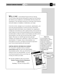
INFORMATION
AND
TROUBLESHOOTING
GUIDE
FOR
MONARCH
‘M’ Series
D.C. HYDRAULIC POWER UNITS
The No. 1 Problem with a unit not working at all is that the threaded ground (GND) has not been
connected to an adequate ground with a cable at least as large as the supply cable size.
Painted or powder coated parts are insulators. Grounds must be to bare metal.
For the most up-to-date version of this guide
Please visit our website @
www.monarchhyd.com
General Information
THIS GUIDE IS MADE AVAILABLE
TO YOU BY
MONARCH HYDRAULICS, INC.
P.O. Box 1764, Grand Rapids, MI 49501-1764, U.S.A.
1363 Michigan St NE, Grand Rapids, MI 49503, U.S.A.
Telephone: (616) 458-1306
Telefax: (616) 458-1616
e-mail: [email protected]
http://www.monarchhyd.com
PLEASE: Before Calling MONARCH be certain that:
1. You have read the guide carefully and are
certain that all of the possible causes pertaining
to your problem have been reviewed.
2. You have the following information available:
a. Model Number _____________________
b. Serial Number _____________________
IMPORTANT
DO NOT VOID YOUR WARRANTY
This guide carries many useful tips for troubleshooting your hydraulic power unit. It should be noted, however, that
any disassembly of a power unit that is still under warranty will void that warranty. If you need any assistance,
contact the factory.
!
i
WARNING
•
Always wear eye protection and protective clothing
when working on and around hydraulic systems.
•
Remove jewelry and objects that might conduct
electricity while working on power units.
•
Hydraulic fluid does pose a fire harard, can cause
burning or skin irritation if not properly handled.
•
Fluid under pressure can pierce the skin and enter
the bloodstream causing death or serious injury.
•
Devices being operated by the hydraulic system
should be immobilized so they cannot move and
cause injury while being inspected or repaired.
Disconnect from electrical source.
•
Prior to performing any maintenance make sure the
equipment is turned off and that any stored energy,
for example pressure, is released. Also, extended
equipment or cylinders should be lowered and
mechanically locked as required.
•
Monarch Hydraulics is not responsible for misuse or
misapplication of product. If you have any questions
about application, please concact local dealer.
•
Fluids should be contained and disposed of properly.
TABLE OF CONTENTS
TOPIC
PAGE
General Information .........................................
Table of Contents .............................................
Test Equipment ................................................
Pressure Gauge ........................................
D.C. Test Light ..........................................
Continuity Light .........................................
Volt Meter ..................................................
OHM Meter ...............................................
Assorted Hoses, High Pressure Fittings ....
High Pressure Shutoff Valve .....................
Hydraulic Fluid .................................................
The Purpose of Oil ....................................
Selecting Fluids for Applications Outside of
ATF’s Temperature Range ........................
Pump Priming ..................................................
New Installations .......................................
On Systems That Fail to Prime or Lose
Their Prime, Check for the Following ........
Reservoirs .......................................................
Use Recommended Fluid ..........................
Correct Filling and Operating Procedure ...
Problems Associated with The Reservoir ..
Tips and Comments ..................................
Filters ..............................................................
Suction Filters ...........................................
Additional Filter Systems ...........................
Electrical Problems ..........................................
Low Voltage ...............................................
D.C. Motors (Wound Field) .......................
D.C. Motors (Permanent Magnet) .............
Electrical Switches ....................................
Shorts, “Grounding Faults” and “Open”
Circuits ......................................................
Solenoid Coils ...........................................
Electrical Polarity .......................................
Relief Valves ....................................................
The Purpose of a Relief is to: ....................
The Two Styles of Relief Valves Used by
Monarch are: .............................................
Diagnosing and Repairing Relief Valves ....
Check Valves ...................................................
Purpose of a Check Valve .........................
Three Types of Check Valves are Used ....
Troubleshooting and Repairing Check
Valve Failures ............................................
i
ii
1
1
1
1
1
1
1
1
1
1-2
TOPIC
PAGE
Directional Control and Specialty Valves ..........
2-Way/2-Position Normally Closed
Valves .......................................................
3-Way/2-Position and 4-Way/2-Position
Valves .......................................................
Specialty Valves ........................................
Tips on Repairs ...............................................
Warning ...........................................................
Notes ...............................................................
D.C. Hydraulic Models .....................................
Part Sheets Available from Monarch ................
13-15
13-14
14-15
15-17
18
18
19
20-22
23
2
2
2
2-3
3
3
3
3-4
4
4
4
4-5
5
5-8
6
6
7-8
8
8
8
8
8
9-10
10-11
11
11
11-12
12
Monarch Hydraulics, Inc.
ii
Maintenance and Troubleshooting Guide for
Monarch D.C. Hydraulic Power Units
!
WARNING
•
Always wear eye protection and protective clothing
when working on and around hydraulic systems.
•
Remove jewelry and objects that might conduct
electricity while working on power units.
•
Hydraulic fluid does pose a fire harard, can cause
burning or skin irritation if not properly handled.
•
Fluid under pressure can pierce the skin and enter
the bloodstream causing death or serious injury.
•
Devices being operated by the hydraulic system
should be immobilized so they cannot move and
cause injury while being inspected or repaired.
Disconnect from electrical source.
•
Prior to performing any maintenance make sure the
equipment is turned off and that any stored energy,
for example pressure, is released. Also, extended
equipment or cylinders should be lowered and
mechanically locked as required.
•
Monarch Hydraulics is not responsible for misuse or
misapplication of product. If you have any questions
about application, please concact local dealer.
•
Fluids should be contained and disposed of properly.
NOTE: Do not use Teflon tape on hydraulic fittings
as it can easily jam valves and plug the filters in the
system.
TEST EQUIPMENT
The following is a list of the test equipment required to
troubleshoot D.C. powered hydraulic systems.
1. PRESSURE GAUGE
A small 0-5000 Pressure gauge, preferable glycerin filled,
is a very valuable and relatively inexpensive tool for
checking pressure in the various sections of the circuit.
2. D.C. TEST LIGHT
A test light is simply a light bulb which has one end
connected by a wire to an alligator clip and the other
end connected to a metal probe. It is used to check the
electrical circuit when the battery is connected to the
system. The alligator clip is grounded and the light
glows when the probe comes in contact with a “HOT”
electrical component. They are easily obtained from
automotive jobbers or discount stores.
3. CONTINUITY LIGHT
A continuity light is like a test light but contains its own
battery power source. It is used for testing electrical
circuits when the components are not connected to a
battery. They are easily obtained from discount stores
or electrical jobbers at modest cost.
4. VOLT METER
A D.C. volt meter, as used in the automotive repair
business, is a good investment for troubleshooting
problems that are related to low voltage. They are used
in two ways: first, one probe is grounded while the
other is used to probe the “HOT” leads, the meter
shows the voltage available at the point where the
second probe is connected; second, they can be used
to measure a voltage drop in a wire, one probe is
connected to one end and the remaining to the other
end, the reading is the voltage drop.
5. OHM METER
An ohm meter is used to measure resistance and is a
very useful tool when working on wire circuits and
solenoid coils. On some coils the wire resistance is up
to a level where a D.C. test light might show an open
circuit and it really is not so. An infinite meter reading
on any test shows that the circuit is open. A coil test,
however, will always show some value of resistance but
it must not be infinite. All tests conducted with an ohm
meter must be done with the battery disconnected from
the system.
6. ASSORTED HOSES, HIGH PRESSURE FITTINGS
These can be used to connect and/or isolate certain
parts of a hydraulic circuit to a pressure gauge or a
shutoff valve for diagnosing hydraulic problems. 1/4"
NPT and 3/8" NPT are the most commonly used sizes.
7. HIGH PRESSURE SHUTOFF VALVE
The shutoff valve can be used to choke off oil flow so
that a “false” load can be put on the pump and other
components. With the valve installed it can be slowly
shut off while the equipment listed above records the
data for making a proper diagnosis.
HYDRAULIC FLUID
1. THE PURPOSE OF OIL
The main purpose of hydraulic fluid is to transfer power
from the pump to the actuators but it must also perform
many other tasks which are critical to a well designed
system. First, the oil must have good lubricity or be
“slippery” so that the friction will be as low as possible to
keep metal to metal wearing at a minimum. Second, the
viscosity or “thickness” must be in the proper range at
Monarch Hydraulics, Inc.
1
the operating temperature so that unwanted leakage will
be at a minimum, but will still allow the oil to lubricate
the close fitting parts in the system. (Oil that is too thin
will leak past seals, valve spools, and the gears; Oil that
is too thick will not flow properly and cause the pump to
cavitate or starve.) Third, the oil must be compatible
with the seals used in the system. Fourth, there should
also be additives in the oil to slow down the effects of
rust, oxidation (oxygen in the air combining with the oil
to form sludge) foaming, and water settling to the
bottom of the reservoir. Fifth, the oil must be able to
pour or flow at the lowest expected temperature so that
the oil can reach or get into the pump. Sixth, the oil
should contain EP (extreme pressure) additives to
prevent breaking down the fluid.
For all the reasons just listed, automatic transmission
fluid (ATF) was found, in most cases, to be the best
fluid readily available in most climate conditions.
2. SELECTING FLUIDS FOR APPLICATIONS
OUTSIDE OF ATF’S TEMPERATURE RANGE
When looking for fluids that can be used in the place of
automatic transmission fluid, or for applications where
the operating temperature is outside of the range of
automatic transmission fluid, the following specifications
should be discussed with your local oil distributor:
A. Fluid must be compatible with Buna-N sealing
compounds.
B. The pour point must be below the lowest anticipated
temperature that will be encountered.
C. It should contain Rust and Oxidation as well as
other detergent type inhibitors.
D. The Viscosity (SUS) should lie between 80 as a
minimum and 375 as a maximum in the operating
range, with ideal viscosity near 200 SUS.
E. The viscosity index should be as high as possible.
As an example, automatic transmission fluid (ATF)
has the following specifications as listed by most oil
manufacturers:
A. Viscosity (SUS)
100°F.
210°F.
B. Pour Point
C. Viscosity Index
185 to 205
45 to 55
-45°F. to -35°F.
145 to 165
NOTE: In an emergency for cold weather applications
SAE 10W oil mixed by volume with no more than 30%
#1 fuel oil or kerosene can be used. (It must be removed when the weather warms).
2
!
WARNING
•
Always wear eye protection and protective clothing
when working on and around hydraulic systems.
•
Remove jewelry and objects that might conduct
electricity while working on power units.
•
Hydraulic fluid does pose a fire harard, can cause
burning or skin irritation if not properly handled.
•
Fluid under pressure can pierce the skin and enter
the bloodstream causing death or serious injury.
•
Devices being operated by the hydraulic system
should be immobilized so they cannot move and
cause injury while being inspected or repaired.
Disconnect from electrical source.
•
Prior to performing any maintenance make sure the
equipment is turned off and that any stored energy,
for example pressure, is released. Also, extended
equipment or cylinders should be lowered and
mechanically locked as required.
•
Monarch Hydraulics is not responsible for misuse or
misapplication of product. If you have any questions
about application, please concact local dealer.
•
Fluids should be contained and disposed of properly.
PUMP PRIMING
1. NEW INSTALLATIONS
New system installations, as well as those that are
disassembled for repair, require proper priming to avoid
possible pump failure. A pump is said to be “primed”
when the internal cavity is full of oil and the air has been
expelled. Prime a pump as follows:
A. “Crack” or remove the high pressure line at or
near the cylinder.
B. “Jog” the unit until oil flow is clear (Air is absent).
C. Retighten or replace hose.
2. ON SYSTEMS THAT FAIL TO PRIME OR LOSE
THEIR PRIME, CHECK FOR THE FOLLOWING:
A. Correct unit mounting position. Failure to
mount the pump in the proper manner could
mean that the pump cannot prime (pickup oil)
because the suction tube is not submerged in
the oil at all times.
B. Partially clogged suction filter. (See Filter
Section.)
RESERVOIRS
C. A loose or improperly installed suction hose or
pickup tube.
1. USE RECOMMENDED FLUID
Fill reservoir with the approved fluid and refer to the
Hydraulic Fluid Section.
D. A bad front pump seal. (On systems with the
seal cavity connected to suction.)
E. A solid fill plug in reservoir with no vent. (See
Reservoir Section.)
F.
Oil that is too thick - reference Hydraulic Fluid
Section.
G. Occasionally, a pump will not prime itself because a check valve spring in the high pressure
port is too “Stiff” or the spring retainer is turned
down too far. If this condition is expected, loosen
the spring retainer (it is found in the high pressure outlet port), energize the pump to prime it,
and then turn the retainer back to the correct
depth. (See section on check valves.)
!
A. Operate unit several times starting with short
cylinder strokes and increasing length with each
successive stroke.
B. Recheck oil level often and add as necessary to
keep pump from picking up air.
C. After system is completely “bled” check oil level
in reservoir as described in owner’s manual and
install the filler/breather plug provided.
NOTE: Do not use a solid plug or a fill cap without
a filler/breather element or damage will be caused
to pump and/or reservoir.
3. PROBLEMS ASSOCIATED WITH THE
RESERVOIR
WARNING
•
Always wear eye protection and protective clothing
when working on and around hydraulic systems.
•
Remove jewelry and objects that might conduct
electricity while working on power units.
•
Hydraulic fluid does pose a fire harard, can cause
burning or skin irritation if not properly handled.
•
Fluid under pressure can pierce the skin and enter
the bloodstream causing death or serious injury.
•
Devices being operated by the hydraulic system
should be immobilized so they cannot move and
cause injury while being inspected or repaired.
Disconnect from electrical source.
•
Prior to performing any maintenance make sure the
equipment is turned off and that any stored energy,
for example pressure, is released. Also, extended
equipment or cylinders should be lowered and
mechanically locked as required.
•
Monarch Hydraulics is not responsible for misuse or
misapplication of product. If you have any questions
about application, please concact local dealer.
•
2. CORRECT FILLING AND OPERATING
PROCEDURE
Fluids should be contained and disposed of properly.
A. Clear oil flowing out of the fill hole might
indicate that the cylinder(s) rod was not in it’s
retracted position when the reservoir was filled.
B. Foamy oil flowing out of the fill hole points to the
following:
1. Air is present in the system; that is, cylinders and fluid lines. The response usually
is “spongy” and the cylinder moves with
“jerking” motion.
2. There is no drop tube or “down spout” on
the return line so that the oil is not returning
to the bottom of the reservoir.
3. Check for a loose suction tube.
4. The return oil velocity is excessive; to
correct; add a flow control valve to slow
velocity, increase size of “down spout,” add
a diffuser, or use a larger reservoir to
increase depth of oil above the end of the
return tube.
5. Damage to pump seal. (On systems with
the seal cavity connected to suction.)
C. Water in the oil.
Water can enter the reservoir through the fill
hole if the unit is left outdoors or washed with
high pressure washers. Protect the unit,
whenever possible, and change oil regularly to
Monarch Hydraulics, Inc.
3
minimize problems. In cold weather the water
will freeze and the pump will not work until the
ice melts.
4. TIPS AND COMMENTS
A. In most cases the power unit is made to be
mounted either vertically or horizontally and
improper mounting will not allow the reservoir to
be filled to capacity. (See Pump Priming
Section)
B. On units with a remote reservoir try to mount it
above the pump whenever possible to “flood”
the inlet.
C. One of the functions of the reservoir is to keep
the oil in the proper temperature range. If the
reservoir cannot dissipate enough heat increase the size in order to bring the oil temperature down to the proper level. (See Hydraulic Fluid Section).
D. Whenever reinstalling plastic reservoirs make
sure that the hose clamp is torqued to 57 inch
pounds.
!
4
WARNING
•
Always wear eye protection and protective clothing
when working on and around hydraulic systems.
•
Remove jewelry and objects that might conduct
electricity while working on power units.
•
Hydraulic fluid does pose a fire harard, can cause
burning or skin irritation if not properly handled.
•
Fluid under pressure can pierce the skin and enter
the bloodstream causing death or serious injury.
•
Devices being operated by the hydraulic system
should be immobilized so they cannot move and
cause injury while being inspected or repaired.
Disconnect from electrical source.
•
Prior to performing any maintenance make sure the
equipment is turned off and that any stored energy,
for example pressure, is released. Also, extended
equipment or cylinders should be lowered and
mechanically locked as required.
•
Monarch Hydraulics is not responsible for misuse or
misapplication of product. If you have any questions
about application, please concact local dealer.
•
Fluids should be contained and disposed of properly.
FILTERS
1. SUCTION FILTERS
Most Monarch hydraulic controls have suction filters
which must be cleaned periodically or whenever flow is
slow or sluggish. Some filters can be washed in
cleaning solvent and blown dry with compressed air;
those which cannot be cleaned properly should be
replaced. External high pressure filters may be added to
the system for added protection and ease of cleaning.
2. ADDITIONAL SYSTEM FILTERS
A. MODELS M-303,M-503,M-603,M-723,M-3593
These specific models have filters in addition to
the pump suction filter for protecting the valve.
One is located inside the two piece hex fitting
just ahead of the DR (2-way, 2-position) cartridge lowering valve inside the reservoir. It can
be taken apart for cleaning or replacing the filter
element.
B. Models in M-640 Series
These models also are equipped with additional
filters for protecting the solenoid valves. First;
each port, C1, and C2, on the flat surface have
a cone shaped filter in the valve body. They can
be reached as follows:
1. If the ports, C1 and C2, on the flat surface
are not being used, remove the flush 1/4"
pipe plugs.
2. If the ports, C1 and C2 on the flat surface
are being used; remove the hoses.
3. Reach down into these ports with a 1/4"
allen key and remove the filter retainer
screws.
4. Remove the filters and clean or replace as
necessary.
5. Reassemble in reverse order.
NOTE: Each cartridge has a “body” filter to
provide additional protection from dirt. To clean
or replace these filters the valve body must be
removed from the reservoir and the cartridge
removed from the body. Clean with solvent and
compressed air or replace as required.
C. Models in M-670, M-680, and M-690 Series
Like the M-640 series these modes also have
port and cartridge filters. The port filters are
located just below the surface in each outlet
(C1, C2, C3). To clean or replace proceed as
follows:
1.
Remove the hoses from the valve body.
2.
Remove the filter retainer screws with a
1/4” allen key.
3.
Remove and clean or replace filters as
required.
4.
Reassemble in reverse order.
The cartridge “body” filters are removed and
repaired in the same manner as described in
the M-640 Models above.
D. Most cartridge solenoid valves also have “body”
filters located on the cartridge of the valve.
Some can be replaced, others can only be
cleaned.
NOTE: Do not use Teflon tape on hydraulic
fittings as it can easily jam valves and plug
the filters in the system.
!
WARNING
•
Always wear eye protection and protective clothing
when working on and around hydraulic systems.
•
Remove jewelry and objects that might conduct
electricity while working on power units.
•
Hydraulic fluid does pose a fire harard, can cause
burning or skin irritation if not properly handled.
•
Fluid under pressure can pierce the skin and enter
the bloodstream causing death or serious injury.
•
Devices being operated by the hydraulic system
should be immobilized so they cannot move and
cause injury while being inspected or repaired.
Disconnect from electrical source.
•
Prior to performing any maintenance make sure the
equipment is turned off and that any stored energy,
for example pressure, is released. Also, extended
equipment or cylinders should be lowered and
mechanically locked as required.
•
Monarch Hydraulics is not responsible for misuse or
misapplication of product. If you have any questions
about application, please concact local dealer.
•
Fluids should be contained and disposed of properly.
ELECTRICAL PROBLEMS
1. LOW VOLTAGE
Operating direct current (D.C.) power units efficiently
requires proper voltage. Any attempt to operate below
the minimum required voltage could cause system
failure. Refer to Battery Cable Guide. (Following page)
A. Signals which point to low voltages are:
1. The minimum voltage between the motor
stud and ground is 9.0 volts at maximum
load conditions.
2. The minimum voltage between the valve
solenoid power wire (“hot wire”) and ground
is 9-1/2 volts at maximum load conditions.
C. Causes for low voltage are:
1. Battery capacity too small.
2. Cable ends not electrically secure to
battery cable.
3. Battery cable size too small for load and
length of run. See Battery Cable Guide
below. Larger copper battery cable, #1, #0,
or #00, may be required for cable lengths
over 25 feet to keep performance from
deteriorating.
4. Ground cable size not equivalent or larger
than the battery “hotside” cable.
5. Bad joints where cable ends are bolted to
battery, motor solenoid, start switch,
ground and etc.
6. Burnt contacts on motor solenoid or start
switch.
!
PLEASE REMOVE ALL RINGS,
WATCHES AND JEWELRY PRIOR TO
DOING ANY ELECTRICAL
D. Check for low voltage as follows: (A volt meter
will be required).
1. On vehicles equipped with an alternator the
voltage should be approximately 13.5 volts
with no electrical accessories operating
and the engine running - Check it.
2. Operate pump unit under maximum
conditions; this would be either under full
load or when pump is running over relief
(cylinder dead headed). Use the volt meter
to probe each connection, cable end, and
cable from the battery all the way back to
the motor stud and note the voltage losses.
Make the necessary repairs. Increase the
voltage above the minimum required.
NOTE: Check the ground side as well. Paint, rust,
and dirt are insulators - remove them.
Monarch Hydraulics, Inc.
5
#00 Gauge
.3
(7.6 mm)
#0 Gauge
#2 Gauge
#4 Gauge
(Ft.) 70'
.28
(7.1 mm)
60'
.25
(6.4 mm)
.2
(5.1 mm)
50'
Cable Length
#1 Gauge
.35
(8.9 mm)
40'
30'
20'
Actual area of battery cable copper strand bundle.
(Insulation NOT included.)
10'
Battery Cable Guide
100
C. Place a few drops of oil on felt liner in head
assembly.
D. Check brush set for wear and replace if necessary.
E. Blow dirt and dust out of motor housing and
check for shorts, burnt wires, or open circuits in
the field coil assembly.
F.
Check armature and commutator for shorts or
open circuits.
G. Check ball bearing on motor shaft, a growling
motor can be caused by bad bearings.
H. Check for excessive “end play” of armature and
add thrust washers as required. (On motors
designed with a ball bearing on commutator
end make sure the wavy washer is behind the
bearing to thrust it toward the pump.)
NOTE: A motor that does not turn in freezing
weather could be caused by water that has frozen
inside the housing.
I.
6
All D.C. motors turn counterclockwise when
viewed from the drive end - check it when
150
#1 #0 #00
200
250
300
(Amps)
replacing a motor with a new one.
J.
If motor fails to turn the pump, check the pump
by turning the drive shaft by hand - it may be
“setup” and the pump needs replacing. Shaft
rotates clockwise.
A. Remove head assembly from motor.
B. Check sleeve bearing in head assembly for
wear.
#2
Current
2. D.C. MOTORS (Wound Field)
Motors should be serviced periodically to insure proper
performance.
Service as follows:
#4
3. D.C. MOTORS (Permanent Magnet)
Permanent magnet motors are similar to wound field
motors except the field coils are replaced with permanent magnets. If the brush holder is mounted to the
head assembly, it must be aligned with timing marks to
the motor shell. If you cannot find the marks, make your
own before you loosen the bolts. Repair similar to
wound field motor above with exception of the field
coils.
Note: Permanent magnet motors must be handled
with care. Timing marks must be properly aligned
for maximum performance and efficiency. PM
motors have powerful magnets which will attract
ferous materials. Magnets must be kept clean
before inserting the armature . Keep fingers away
from the area between the armature and the motor
case when re-installing the armature in order to
avoid injury.
!
THE MAGNETS WILL PULL THE
ARMATURE INTO THE MOTOR
UPON REINSERTION.
A wiring diagram guide for D.C. power units is also
available. Request form #2347-99.
4. ELECTRICAL SWITCHES
A. Push Button, Toggle and Rocker Types.
Defective switches are a common cause of
electrical malfunction. What seems to be a
serious system defect can often be caused
simply by a faulty switch, especially where the
switch controls two functions, that is: start the
motor, and shift a valve. In those cases one
half of the switch might be defective while the
other half operates correctly and the fault
appears to be with some other component.
Troubleshooting can be done by any one of
three methods:
1. Use a “continuity light” to test switch. (See
Test Equipment).
2. Use a circuit “test light” to test switch. (See
Test Equipment).
3. Remove the wires from the switch and
“touch” them together in the proper order to
operate system.
Note: All switch control stations subjected to the
weather should be mounted so that the cord exits
the bottom to prevent water from entering the box.
B. “Contact finger” switches (Manual Valves).
All models that use a contact finger(s) attached
to the handle or shaft of a manual valve to start
the D.C. motor do so by grounding the small
post of a solenoid start switch. When repairing
systems with contact fingers check for the
following:
1. 3 Post Solenoid Switch ( Fig 1.) (Insulated
Can)
a. The three post solenoid switch is wired
and constructed as follows:
(1.) The large post marked “Bat” must be
attached to the cable leading from
the battery.
(2.) The small post connects to the
control circuit. (Contact finger,
push button, toggle switch, etc.)
(3.) The remaining large post
attaches to the cable leading from
the motor.
Note: Do not attach motor cable to post marked
“Bat” as solenoid will not operate properly.
(4.) Internally, the coil is constructed with
one end connected to the post
marked ‘Bat” and the other end to the
small center-post. With the battery
cable connected to the post marked
“Bat”, the solenoid switch is energized
by grounding the small post; which in
turn closes the main contacts and
starts the motor.
b. Testing for a faulty solenoid switch:
When testing use an OHM meter, continuity light, or test light, and check all
functions as described above. (See Test
Equipment Section).
2. 3 Post Solenoid Switch ( Fig 2.) (Ground to
Can)
1. Improperly aligned or broken contact finger.
2. Nub nut assembly that is not insulated from
ground.
FIG. 2
3. Wires that are bare or shorted to ground.
C. Motor Start Solenoid Switches.
Although there are exceptions most solenoid
switches found on Monarch systems are one of
the following three types:
FIG. 1
Battery
Terminal
+
Insulated Can
Grounded Can
a.The three post solenoid switch is wired
and constructed as follows:
(1.) One large post must be attached to
the cable leading from the battery.
(2.) The small post connects to the
control circuit. (Push button, rocker
switch or toggle, etc.)
(3.) The shared “hot” lead from the
control circuit must also be attached
to the large post from the battery.
Monarch Hydraulics, Inc.
7
(4.) The remaining large post attaches to
the cable leading from the motor.
3. 4 Post Solenoid Switch ( Fig 3.) (Isolated
Ground)
FIG. 3
Isolated Ground
a. The four post solenoid switch is wired
and constructed as follows:
(1.) One large switch post is connected
to the battery cable (either one).
(2.) The remaining large post is connected to the motor cable.
(3.) The 2 small posts are connected to
the coil, one post to each end.
(4.) With access to both ends of the coil,
the specific wiring arrangements
can be varied, but to energize the
coil one lead has to be positive and
the other end negative.
b. Testing for a faulty solenoid switch:
When testing use an OHM meter, continuity light, or test light, and check all
functions as described above. (See
Test Equipment Section).
5. SHORTS, “GROUNDING FAULTS” AND “OPEN”
CIRCUITS
In control wiring, shorts can only occur when “hot” lines
(lines connected directly to the battery) come in contact
with ground. A short will either cause a fuse to blow, if
there is one, or burn the wire off at its weakest point.
Likely spots for shorts are switches, electrical strain
relief, electrical junction boxes, and control cord(s) that
have been pinched or cut.
6. SOLENOID COILS
Coils are used in solenoid operated valves and solenoid start switches. Failures can be caused by vibration, water, improper voltage, or corrosion. The best
way to test a coil is with an OHM meter. The meter
should read some value of OHMS and an infinite
reading means that the coil has an open circuit. The
reading between any lead on the coil and the “can”
should be infinite unless there is only one lead wire and
the coil is grounded to the can.
8
7. ELECTRICAL POLARITY
Motors and valves supplied by Monarch can be used on
either positive or negative ground systems with the
exception of the model M-310 or any system using the
round (cylindrical shaped) manual valve with a covered
switch on the back plate. In these units there is a
capacitor connected on the switch which must be
“polarized.” They are normally wired for negative ground
systems and if used on a positive ground system the
capacitor must be turned end for end as the + sign must
face the most positive side of the circuit. Failure to align
properly will cause the lead wire to “blow” off the
capacitor, which in turn could make a “ground fault” and
cause the motor to run with no control.
NOTE: Do not use teflon tape on hydraulic fittings
as it can easily jam valves and plug the filters in the
system.
!
WARNING
•
Always wear eye protection and protective clothing
when working on and around hydraulic systems.
•
Remove jewelry and objects that might conduct
electricity while working on power units.
•
Hydraulic fluid does pose a fire harard, can cause
burning or skin irritation if not properly handled.
•
Fluid under pressure can pierce the skin and enter
the bloodstream causing death or serious injury.
•
Devices being operated by the hydraulic system
should be immobilized so they cannot move and
cause injury while being inspected or repaired.
Disconnect from electrical source.
•
Prior to performing any maintenance make sure the
equipment is turned off and that any stored energy,
for example pressure, is released. Also, extended
equipment or cylinders should be lowered and
mechanically locked as required.
•
Monarch Hydraulics is not responsible for misuse or
misapplication of product. If you have any questions
about application, please concact local dealer.
•
Fluids should be contained and disposed of properly.
RELIEF VALVES
1. THE PURPOSE OF A RELIEF VALVE IS TO:
A. Keep the maximum system pressure at a safe
level.
FLOW
5
4
3
2
1
1. LOOSEN JAM NUT. (1)
2. TURN SCREW CLOCKWISE TO INCREASE
PRESSURE. (3)
3. TURN SCREW COUNTER-CLOCKWISE TO
DECREASE PRESSURE. (3)
NOTE:
OUTLET PORT FLOW MUST BE BLOCKED TO
MAKE RELIEF VALVE OPERATE WHILE
ADJUSTING.
RELIEF (STD.)
FIG. 4
4. TIGHTEN JAM NUT. (1)
FLOW
SPRING
4
3
2
1
1. REMOVE FLUSH PLUG. (1)
2. TURN SCREW CLOCKWISE TO INCREASE
PRESSURE. (2)
3. TURN SCREW COUNTER-CLOCKWISE TO
DECREASE PRESSURE. (2)
NOTE:
OUTLET PORT FLOW MUST BE BLOCKED TO
MAKE RELIEF VALVE OPERATE WHILE
ADJUSTING.
OLD STYLE RELIEF
4. REINSTALL FLUSH PLUG. (1)
FIG. 5
B. Keep the amp draw and battery drain at a
minimum when the cylinder “dead heads”
(reaches full stroke).
2. THE TWO STYLES OF RELIEF VALVES USED
BY MONARCH ARE:
A. Loose Component Style
1. Internal Cavity with Loose Components.
(See Fig. 4 & 5).
An “internal” cavity is drilled into the pump base
into which the following parts are inserted to
make up the relief valve assembly.
a. Ball or cone, heavy spring, and in some
cases a jam nut and seal washer.
B. Cartridge Style. (See Fig.6)
A complete cartridge is assembled into an
intregal cavity.
Monarch Hydraulics, Inc.
9
Note: On applications where the cylinder is being
replaced or the mechanical mechanism is being
modified, make sure the pressure capability of the
pump is not being exceeded.
FLOW
1
2
CARTRIDGE RELIEF VALVE
FIG. 6
3. DIAGNOSING AND REPAIRING RELIEF VALVES
NOTE: When testing or making adjustments on the
relief valve the system must be “dead headed”
(cylinder at full stroke or in a position where cylinder movement is zero).
A. Relief Valve Pressure Too High
1. Symptoms:
a. Amp draw and battery drain excessive
when system is “dead headed”.
b. Motor RPM is slow in comparison to
full load system operation.
2. Repair Procedure:
a. Turn relief valve adjusting screw counterclockwise using a gauge, tee’d into
the high pressure line, to record the
proper pressure setting. (See Fig. 4 &
5). In style shown in Fig 4 loosen jam
nut. In style shown in Fig 5 remove flush
plug.
NOTE: When adjusting the relief valve be sure to
use a pressure gauge and consult with the manufacturer for the proper pressure setting. Failure to
accurately set the relief valve can cause failure
resulting in damage to the equipment or cause
bodily harm.
B. Relief Valve Pressure Too Low
1. Symptoms:
a. Motor RPM is faster than normal.
b. Cylinder will not extend.
c. Excessive turbulence in the reservoir.
10
2. Repair Procedure.
a. There are 2 possible causes for lack of
pressure.
(1) The adjusting screw has backed
up.
(2) Foreign matter or “dirt” is trapped
between the seat and the ball or
cone.
b. Repair as follows:
(1) Using a gauge, tee’d into the
pressure line, loosen the jam nut
and turn the adjusting screw
clockwise a turn or two and watch
the gauge; if it goes up, continue to
turn the screw until the required
setting is reached. Retighten the
jam nut. In the “Old Style” relief, if
the screw does not remain in the
correct position use one with a
patch. (In an emergency the screw
threads can be deformed slightly
with a small prick punch and
hammer).
(2) If the pressure does not increase
when the adjusting screw is
tightened; turn the adjusting screw
counterclockwise all the way out;
energize the pump to “flush” the dirt
past the seat.
Inspect the cone or ball for nicks
and replace it if necessary; reseat
the ball or cone using a small drift
punch and hammer with a light tap;
reinstall the spring and adjusting
screw and reset the pressure.
(3) If you are replacing a cartridge
relief valve it cannot be readily
disassembled. Push a blunt object
into the nose area to push the
poppet after you have the screw
backed off as far out as possible.
Blow compressed air thru side port
to try and get dirt to “exit” the way it
“entered”. Pick it out if possible. If
you cannot dislodge the contamination you will need to replace the
cartridge.
(4) If the above mentioned procedure
fails to increase the relief valve
setting, check for a worn pump or
leaking cylinder.
FLOW
Note: Do not use teflon tape on hydraulic fittings
as it can easily jam valves and plug the filters in the
system.
!
•
Always wear eye protection and protective clothing
when working on and around hydraulic systems.
•
Remove jewelry and objects that might conduct
electricity while working on power units.
•
Hydraulic fluid does pose a fire harard, can cause
burning or skin irritation if not properly handled.
•
Fluid under pressure can pierce the skin and enter
the bloodstream causing death or serious injury.
•
Devices being operated by the hydraulic system
should be immobilized so they cannot move and
cause injury while being inspected or repaired.
Disconnect from electrical source.
•
Prior to performing any maintenance make sure the
equipment is turned off and that any stored energy,
for example pressure, is released. Also, extended
equipment or cylinders should be lowered and
mechanically locked as required.
•
Monarch Hydraulics is not responsible for misuse or
misapplication of product. If you have any questions
about application, please concact local dealer.
•
BALL CHECK
WARNING
FIG. 7
B. Poppet Type
A Poppet Type check valve is made up of the
following: (See Fig. 8, 9, 10 &11)
• Ball
• Ball Follower
• Light Spring
• Spring Retainer
FLOW
Fluids should be contained and disposed of properly.
POPPET CHECK
FIG. 8
CHECK VALVES
1. PURPOSE OF A CHECK VALVE
To allow free flow in one direction but block reverse
flow.
2. THREE TYPES OF CHECK VALVES ARE USED
A. Ball Type
A Ball Type Check Valve is made up of the
following: (See Fig.7)
• Ball
• Light Spring
• Spring Retainer
FLOW
M-250 SERIES POPPET CHECK
FIG. 9
Monarch Hydraulics, Inc.
11
3. TROUBLESHOOTING AND REPAIRING CHECK
VALVE FAILURES
SCREW FLUSH TO 1/32" DEEP
FROM BOTTOM OF S-FACE
A. Load Drift Failure
1. Symptom
In most cases a check valve will fail such
that the load will drift down when the unit is
in the “hold” position.
2. Repair Procedures (Loose Parts Design)
a. Remove the spring retainer.
FLOW
M-3598 POPPET CHECK
NOTE: Measure the depth of the retainer so it can
be reassembled to the same depth after repair.
FIG. 10
RETURN
FLOW
FLOW
M-313 MAIN POPPET CHECK AND LOWERING VALVE
FIG. 11
C. Cartridge Type
A Cartridge Type Check Valve is made up of a
ball or poppet in a completely contained cartridge. (See Fig 12).
FLOW
CARTRIDGE CHECK VALVE
FIG. 12
12
b. Remove spring.
c. Remove ball or follower and ball.
d. Start pump to “flush” dirt from the seat
area. (Caution: divert oil into a container. Do not look into the port).
e. Inspect the ball for damage and
replace if necessary.
f. Reinstall ball or ball and follower.
g. “Seat” the ball using a small drift punch
and hammer with a light tap.
h. Reinstall the spring.
i. Replace the spring retainer to the
correct depth.
3. Repair Procedure (Cartridge)
a. Remove cartridge and clean or replace
(See Specialty Valve Section A)
B. Blocked Flow Failure
1. Symptom
Once in a while a ball type check valve will
restrict flow to the point where the spring
will collapse and the flow will be greatly
reduced (even blocked) causing flow over
relief.
2. Repair Procedure (Loose Parts Design)
a. Remove the check valve components
and replace the spring.
b. If the problem persists replace the ball
type with a poppet type as they cannot
completely block flow.
c. Adjust screw to proper depth.
3. Repair Procedure (Cartridge)
a. Replace cartridge (See Specialty Valve
Section A)
!
WARNING
•
Always wear eye protection and protective clothing
when working on and around hydraulic systems.
•
Remove jewelry and objects that might conduct
electricity while working on power units.
•
Hydraulic fluid does pose a fire harard, can cause
burning or skin irritation if not properly handled.
•
Fluid under pressure can pierce the skin and enter
the bloodstream causing death or serious injury.
•
Devices being operated by the hydraulic system
should be immobilized so they cannot move and
cause injury while being inspected or repaired.
Disconnect from electrical source.
•
Prior to performing any maintenance make sure the
equipment is turned off and that any stored energy,
for example pressure, is released. Also, extended
equipment or cylinders should be lowered and
mechanically locked as required.
•
Monarch Hydraulics is not responsible for misuse or
misapplication of product. If you have any questions
about application, please concact local dealer.
•
Fluids should be contained and disposed of properly.
DIRECTIONAL CONTROL AND SPECIALTY
VALVES
1. 2-WAY/2-POSITION NORMALLY CLOSED
VALVES
These valves allow for free flow in one direction (from
the bottom port to the side ports) at all times and
checked flow in the opposite direction until the solenoid
coil is energized. (See Fig. 13 )Troubleshoot and repair
as follows:
A. If the valve does not shift, check for and repair
the following:
1. The valve “hot” wire. (See section on Open
Circuits).
2. The valve ground wire. (See section on
Open Circuits).
3. The switch controlling the valve. (See
section on Electrical Switches).
4. Low Voltage. (See section on Low Voltage).
5. The solenoid coil. (See section on Solenoid Coils).
6. Dirt in the valve cartridge. This can be
2 WAY 2 POSITION VALVE & COIL
FIG. 13
done by energizing the valve without
starting the motor and listening for the
valve to shift (a definite “Click” is heard
when the valve in energized. If the valve
does not shift, remove the cartridge from
the valve body. Blow compressed air
through the cartridge in both directions
while holding the plunger off its seat (use a
blunt object inserted through bottom of
cartridge). It will help to have the “body”
filter removed.
7. A bent valve stem. Replace valve.
NOTE: The cartridge itself cannot be disassembled
in the field as the proper tolerances cannot be
duplicated. If the dirt cannot be removed the
cartridge will have to be replaced.
Monarch Hydraulics, Inc.
13
B. If the valve does not return to the neutral or
unshifted position, check for dirt in the valve
cartridge or a bent stem.
2. 3-WAY/2-POSITION AND 4-WAY/2-POSITION
VALVES
Troubleshoot and Repair As Follows: (See Fig. 14
and Fig. 15 )
4 WAY 2 POSITION VALVE & COIL
FIG. 15
3 WAY 2 POSITION VALVE & COIL (SHOWN
WITH MANUAL OVER-RIDE OPTION)
FIG. 14
A. If the valve does not shift, check for and repair
the following:
1. The valve “hot” wire. (See section on Open
Circuits).
14
2. The valve ground wire. (See section on
Open Circuits.
3. The switch controlling the valves. (See
section on Electrical Switches).
4. Low Voltage. (See section on Low Voltage).
5. The Solenoid Coil. (See section on
Solenoid Coils).
6. Dirt in the valve cartridge. This can be
done by energizing the valve without
starting the motor and listening for the
“valve shift”. If it cannot be heard, remove
the cartridge from the valve body and blow
compressed air through all parts to dislodge
dirt. Clean all parts in solvent, blow dry,
and lubricate.
B. If the valve does not return to the neutral or
unshifted position, check for dirt in the valve
cartridge and repair in the same manner as
above.
3. SPECIALTY VALVES:
A. Cartridge Style Check Valves.
These valves screw into a cartridge cavity and
allow for free flow from the end to the side and
block reverse flow. (See Fig. 12)
Troubleshoot and Repair as Follows:
If the valve does not hold, remove the
cartridgefrom the housing. Blow compressed
air through the cartridge from the side to the
bottom while holding the ball or poppet off the
seat (use a blunt object inserted through the
bottom of the cartridge to hold the poppet off
the seat.
NOTE: The valve itself cannot be disassembled in
the field; replace it if cleaning does not the problem.
B. Pressure Compensated Orifice.
The valves are “normally” installed in the return
portion of a hydraulic circuit. They maintain a
“more constant” flow even if the pressure is
changing. They are made by “matching” an
orifice to a special spring so they can meter
flow.
If flow is blocked it could be because a particle
of dirt has covered the orifice hole in the piston.
It could also be caused by a piston that has
“over travelled” the return ports in the side of
the housing and has become “jammed” in
contamination at the bottom of the cavity. The
inner housing and piston can be removed as an
assembly. Inspect orifice hole for dirt and blow
compressed air through side holes to dislodge
contamination. Push on inner piston with a
blunt object and observe the piston moving past
side holes in the housing. If it is smooth, it is
working properly. If it is sticky, remove push clip
and disassemble. Clean with solvent and
compressed air, oil the parts, and reassemble.
Do not use emery paper or steel wool to polish
parts or touch orifice with a pick or drill bit
(compressed air only). Replace as an assembly if it does not work properly.
C. Adjustable Flow Control.
This valve has a needle to adjust oil flow in the
direction of the arrow. It has an internal check
valve so reverse flow (opposite the arrow) is
unaffected by the needle.
Troubleshoot and Repair as Follows: (See Fig.
17).
CONTROLLED FLOW
DIREC TION
Troubleshoot and Repair as Follows: (See Fig.
16)
COMPENSATED FLOW
COMPENSATED FLOW
CONTROLLED FLOW
ADJUSTABLE FLOW CONTROL VALVE
PRESSURE COMP FLOW DIRECTION
PRESSURE COMPENSATED ORIFICE
FIG. 16
FIG. 17
Open needle by loosening the jam nut on the
stem and turn the stem out. Inspect for dirt in
ports and remove if possible. Blow com-
Monarch Hydraulics, Inc.
15
Troubleshoot and Repair as Follows:
pressed air through valve first against the arrow
and then with the arrow. Turn needle to full
closed position (do not jam on seat or permanent damage could result). If compressed air is
blown against the direction of the arrow it will
pass through the valve freely; if compressed air
is blown in the direction of the arrow it will be
blocked or almost blocked. If this is not true,
replace the valve; make sure the arrow points in
the proper direction.
“Dead Head” the port in question. Tee a gauge
into the port, start pump and note pressure. If it
is too high the adjusting screw will need to be
turned counterclockwise (use 1/4" allen key). If
it is too low, turn the adjusting screw clockwise
a turn and note the pressure gauge reading.If it
does not move turn screw counterclockwise,
start pump, and flush dirt past the ball. Then,
turn the screw to the proper pressure setting.
Note that the screw threads can be deformed
slightly with a small prick punch and hammer to
hold the pressure setting. Also see: Relief
Valve section for more general information.
D. Adjustable Needle Valve.
This valve has a needle to adjust oil flow . It
affects flow in either direction.
Troubleshoot and Repair as Follows:
Open needle by loosening the jam nut on the
stem and turn the stem out. Inspect for dirt in
ports and remove if possible. Blow compressed air through valve. Turn needle to full
closed position (do not jam on seat or permanent damage could result). Blow compressed
air into one port and check to see if it is blocked
from exiting the other. Replace if dirt cannot be
removed.
F.
Cartridge Type Port Relief (See section above
and Fig. 6 on Cartridge Relief Valves for repair).
G. Double Pilot Operated Checks.
E. Inline “External” Relief Valve (Port Relief).
This valve is made up of a housing (usually
hex), ball, spring, and an adjustable screw. Its
usual function is to control a port at a lower
pressure than the “main” relief in the pump
base. (See Fig. 18)
BALL
SPRING
SCREW
HOUSING
DOUBLE PILOT OPERATED CARTRIDGE CHECK
FIG. 19
FLOW
EXTERNAL RELIEF VALVE
FIG. 18
16
Two styles of Double Pilot Operated checks are
used. One is a cartridge type (See Fig. 19).
The other is made up of two check valves and a
pilot piston complete with springs (See Fig. 20).
Both styles can be cleaned by blowing compressed air through them. But the cartridges
cannot be disassembled. Replace the valves if
air does not dislodge the contamination.
SPRINGS
4
3
1
4
2
PISTON
3
CROSS CHECK WITH MANUAL OVERRIDE
SCREW ACTUATOR STYLE SHOWN ALSO
AVAILABLE WITH PLUNGER
FIG. 21
1
2
DOUBLE PILOT OPERATED CHECK
FIG. 20
H. Double Cross Over Relief Valves
There are two styles used. One style is made
up of a loose ball, spring, screw seal and a jam
nut. Clean as described in Relief Valve section
“2 A” . The other is a cartridge relief. See Relief
Valve section “2 B” for cleaning instructions.
I.
Lowering Valves
Manual lowering valves are used in power up/
gravity down circuits, as either a primary
lowering device using a plunger, or as a backup device using a screw. They are made using
a ball and spring with an actuator to dis-lodge
the ball. They can be repaired like internal
check valves. See Check Valve Section on ball
valves. (See Fig. 11 and Fig. 21 & 22).
M-311 LOWERING VALVE
FIG. 22
Monarch Hydraulics, Inc.
17
TIPS ON REPAIRS
1. Do not screw cartridge valves into cavity too
fast; use a back and forth motion and have Orings well lubricated.
2. Clean all parts thoroughly before assembly and
lubricate with clean oil.
3. Do not use Teflon tape on hydraulic connections as it can easily jam the valves and plug
the filters in the system.
4. Use care when working on electrical components to prevent shorts, “ground faults”, and
“open” circuits.
5. Remove all rings, watches and jewelry that
might come into contact with electrical connections prior to working on the electrical system.
!
18
WARNING
•
Always wear eye protection and protective clothing
when working on and around hydraulic systems.
•
Remove jewelry and objects that might conduct
electricity while working on power units.
•
Hydraulic fluid does pose a fire harard, can cause
burning or skin irritation if not properly handled.
•
Fluid under pressure can pierce the skin and enter
the bloodstream causing death or serious injury.
•
Devices being operated by the hydraulic system
should be immobilized so they cannot move and
cause injury while being inspected or repaired.
Disconnect from electrical source.
•
Prior to performing any maintenance make sure the
equipment is turned off and that any stored energy,
for example pressure, is released. Also, extended
equipment or cylinders should be lowered and
mechanically locked as required.
•
Monarch Hydraulics is not responsible for misuse or
misapplication of product. If you have any questions
about application, please concact local dealer.
•
Fluids should be contained and disposed of properly.
NOTES :
Monarch Hydraulics, Inc.
19
D.C. Hydraulic Models
Typical Location of Basic Parts:
1. Relief Valve
2. Port Outlets
2-A 3/8" Pipe - High Pressure
2-B 1/4" Pipe - High Pressure
3. Suction Filter
4. Motor Start Solenoid Battery Post
5. Fill - Vent Plug
6. Check Valves
7. Port Filter Locations
9. Specialty Valves
8. Valves
9-A Pressure Compensated Orifice
8-A Lowering Valve
9-B Adjustable Flow Control
8-B Port Relief
8-C Lowering Valve
8-D Lowering Valve
8-E Cartridge Check
8-F Lowering Valve
2A
8-G Selector Valve
8-H 2-Way/2-Position Valve
6
8-J 4-Way/2-Position Valve
8-K 3-Way/2-Position Valve
4
8C
M-303
2B
1
5
OUTLET PORT
3/8 NPT REF
3
M
SHOWN WITH OPTIONAL
MOTOR START SOLENOID
SWITCH AND STRAP
OUTLET PORT
3/8 NPT REF
2A
6
M
M-304
5
1
3
20
4
M-258
PORT
1
8C
TO
BATTERY
6
M
8A
4
2A
6
OUTLET PORT
5
M
SHOWN WITH
OPTIONAL MOUNTING
BRACKET
1
M-3519
3
8J
4
8H
M-3551
6
2
C2
C1
9A
5
1
C2 PORT RV
PRESS. COMP.
ORIFICE
8B
SHOWN WITH OPTIONAL
MOUNTING BRACKET
MAIN RV
+
M
3
Monarch Hydraulics, Inc.
21
Typical Location of Basic Parts:
1. Relief Valve
2. Port Outlets
2-A 3/8" Pipe - High Pressure
2-B 1/4" Pipe - High Pressure
3. Suction Filter
4. Motor Start Solenoid Battery Post
5. Fill - Vent Plug
6. Check Valves
7. Port Filter Locations
9. Specialty Valves
8. Valves
9-A Pressure Compensated Orifice
8-A Lowering Valve
9-B Adjustable Flow Control
8-B Port Relief
8-C Lowering Valve
8-D Lowering Valve
8-E Cartridge Check
8-F Lowering Valve
8-G Selector Valve
8-H 2-Way/2-Position Valve
8-J 4-Way/2-Position Valve
8-K 3-Way/2-Position Valve
4
M-683
C2
C1
C3
5
C
A
B
8H
M
8J
8B
8H
8K
M-3593
5
C3
C2
4
1
M
22
C1
The following parts sheets are available from Monarch for the following DC Power Unit models:
Form Number
Model Number
2234
2235
2155
2156
2157
2263
2195
2159
2242
2160
2161
2223
2253
2225
2254
2162
2163
2164
2220
2174
2175
2176
2177
2178
2179
2181
2182
2183
2212
2184
2231
2364
2232
2365
M-258
M-259
M-301
M-303
M-304
M-310
M-311
M-313
M-314
M-319
M-326
M-342
M-342-08
M-352
M-352-08
M-500, 3-Way
M-500, 4-Way
M-500, 4-Way/3-Way
M-628 & 629
M-641
M-642
M-644
M-645
M-647
M-668
M-682
M-683 through M-688
M-693
M-719
M-721
M-3519
M-3519-HF
M-3551
M-3551-HF
2236
Hand Pump
2347
Wiring Guide for Monarch DC Power Units
Monarch Hydraulics, Inc.
23
U.S.A.:
MONARCH HYDRAULICS, INC.
P.O. Box 1764, Grand Rapids, MI 495011764, U.S.A.
1363 Michigan St NE, Grand Rapids, MI
49503, U.S.A.
Telephone: (616) 458-1306
Telefax: (616) 458-1616
http://www.monarchhyd.com
Form No. 2369-03
CANADA:
FLUID-PACK CORPORATION
A Part of the Monarch Hydraulics Group
460 Newbold St., London, Ontario, Canada
N6E 1K3
Telephone: (519) 686-5900
Telefax: (519) 686-8976
Litho in U.S.A.