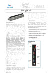
1
SERVICE MANUAL
PK-301/PK320/PK301 PLUS
Date
Revise Version
Description
2010.04.15
V1.0
Initial Issue
2010.08.04
V2.0
Add “System reset“ & change burn-in test in Chapter 4
Add an action to show ”System Upgrade” & FW
version checking in Chapter 5
2011.08.23
V3.0
Add PK320
2012.10.19
V4.0
Add PK301 PLUS
Copyright Oct 2012. All Rights Reserved
Prepared: Cherry
Check:Amy
Approved: Alick
Preface
This manual is applied to PK-301/PK320/PK301 PLUS projection system. The manual
gives you a brief description of basic technical information to help in service and maintain
the product.Your customers will appreciate the quick response time when you immediately
identify problems that occur with our products. We expect your customers will appreciate
the service that you offer them.
This manual is for technicians and people who have an electronic background. Please
send the product back to the distributor for repairing and do not attempt to do anything that
is complex or is not mentioned in the troubleshooting.
Note: The information found in this manual is subject to change without prior notice. Any
subsequent changes made to the data herein will be incorporated in future edition.
PK-301/PK320/PK301 PLUS Service Manual
Copyright Oct 2012
All Rights Reserved
Manual Version 4.0
PK-301/PK320/PK301 PLUS
Confidential
I
PK-301/PK320/PK301 PLUS Comparison List
Parts
Top Cover
Module
PK-301
Main Board
80.8CU01G002
PK301 PLUS
75.8CU05G001
PK320
75.8MH01G001
80.8RF01G001
80.8MH01G001
Keypad
80.8CU03G001
80.8MH03G001
Key Button
51.8CU16G101
51.8MH01G001
Focus Ring
51.8CU14G001
51.8CU14G011
Engine
70.8CU02GR01
70.8MH06GR01
PK-301/PK320/PK301 PLUS
Confidential
II
Table of Content
Chapter 1
Introduction
Highlight
1-1
Compatible Mode
1-2
Chapter 2 Disassembly Process
Equipment Needed & Product Overview
2-1
Disassemble Battery Cover Module
2-2
Disassemble Bottom Cover Module
2-2
Disassemble Main Board Moduleand Rear Cover Module
2-3
Disassemble Fan Module and Engine Module
2-5
Disassemble Keypad Module
2-6
Disassemble the Bottom Cover
2-7
Chapter 3 Troubleshooting
Equipment Needed
3-1
Main Procedure
3-2
Power Troubleshooting
3-3
Image Performance Troubleshooting
3-4
Audio Troubleshooting
3-7
Chapter 4 Function Test & Alignment Procedure
Test Equipment Needed
4-1
Service Mode
4-1
System Reset
4-1
Test Condition
4-2
Test Inspection Procedure
4-3
Power and Led indicator
4-3
PK-301/PK320/PK301 PLUS
Confidential
III
PC Mode
4-4
Video Performance
4-6
SD Card Test
4-7
Optical Performance Measure
4-7
Others
4-9
Chapter 5 Firmware Upgrade Equipment Needed
Chapter 6
5-1
Firmware Upgrade Procedure
5-2
EDID Upgrade
Appendix A EDID introduction
6-1
Equipment needed
6-2
Setup procedure
6-3
EDID Key-In Procedure(VGA & HDMI Interface)
6-3
Exploded Image
I
Appendix B Serial Number System Definition XII
PCBA Code Definition
XIII PK-301/PK320/PK301 PLUS
Confidential
IV
Chapter 1
Introduction
1-1 Highlight
No
Item
1
Power Supply
2
3
Resolution
Platform
Description
•� ��������������
Auto-ranging: �������
AC100V ��
~ �����
240V ��
± �����
10%, �������
50-60Hz
DC 20V/2A, 40W (for PK301/PK320)
• Auto-ranging:
�������������� �������
AC100V ��
~ �����
240V ��
± �����
10%, �������
50-60Hz
DC 12V/2A, 20W(for PK301 PLUS)
•� ����
854 ��x ���
480
• PD30A platform
4
Throw ratio
•� ����������������������
1.8 (Distance / Width)
5
Throw Distance
•� �����
0.2m ��
~ ������������������������
5.0m (Mechanical Travel)
0.4m ~ 2.4m (Full optical Performance)
6
Projection Image Size
•� �
5"~120"
7
LED Life
•� �������
10,000 ������
Hours �������
Bright �����
Mode ��
@ �����
11W, ��������������������������
B50/L50*Note Survival
Rate
8
LED Power
9
Altitude
10
Audio
11
Battery
12
13
Focus length
DMD
14
Power consumption
• 11W +/-10 % in Bright Mode
• 1W+/-20 % in ECO Mode(for PK301)
• 1.8W+/-20 %in ECO Mode(for PK320/ PK301 PLUS)
•� �����������
Operating: ��
0 ��
~ ����������
2,500 ft, ����
for ���������
5°C~35°C
2,500 ft ~ 5,000 ft, for 5°C~30°C
5,000 ft ~ 10,000 ft, for 5°C~25°C
•� �����������������
Built-in ��������
Speaker 0.5W
����� x�� 1(for
������������������������
PK301/ PK301 PLUS)
• Built-in Speaker 1W x 1 (for PK320)
• Charge time @25C : <3hour
•� ��������������������
Discharge time @25C :�� 33
������������������
minutes in ����
STD ������������
Mode (for
PK301)
• Discharge time @25C : 25 minutes in STD Mode (for
PK320)
• Discharge time @25C : 30 minutes in STD Mode (for
PK301 PLUS)
•� ��������
22.77mm ��
@ ���
20”
•� ���������
“TI” DMD ��, �������������
0.3” WVGA DMD
• VGA display mode: <16W (Typical) in Bright Mode
(for PK301/PK320) <10W in STD Mode
<5W in ECO mode
• VGA display mode :<21W (Typical) in Bright Mode
(for PK301 PLUS) <10W in STD mode
<7W in ECO mode
PK-301/PK320/PK301 PLUS
Confidential
1-
1-2 Compatible Mode
Computer compatibility
Compatibility
VGA
Video
HDMI
Resolution
V-Sync[Hz]
640 x 480
60Hz
800 x 600
60Hz
1024 x 768
60Hz
1280 x 720
60Hz
1280 x 800
60Hz
1024x600
60Hz
480i / 480P
60Hz
576i / 576P
50Hz
720P
50Hz/60Hz
1080i
50Hz/60Hz
480i / 480P
60Hz
576i / 576P
50Hz
720P
50Hz/60Hz
1080i
50Hz/60Hz
PK-301/PK320/PK301 PLUS
Confidential
1-
Chapter 2
Disassembly Process
2-1 Equipment Needed & Product Overview
1. Screw Bit (+): No.00
2. Hex Sleeves 5mm
3. PK301/PK320/PK301 PLUS unit
* Before you start: This process is protective level II. Operators should wear electrostatic chains.
* Note : - If you need to replace the main board, you have to record the lamp usage hour.
- The disasssemble procedure for PK301/PK320/PK301 PLUS are the same ,we take
PK-301 as an example here.
PK-301/PK320/PK301 PLUS
Confidential
2-
2-2 Disassemble Battery
Cover Module
1. Disassemble the Battery Cover Module (as red arrow directs).
2. Remove the Battery.
2-3 Disassemble Top Cover
Module
1. Unscrew 5 screws from the Bottom Cover (as red circle).
PK-301/PK320/PK301 PLUS
Confidential
2-
2. Unplug the keypad cable.
3. Disassemble Top Cover Module
Note: - There are 3 tenons (as blue circle) on the top cover,when disassembling it, you must be carefull so as not to damage the top cover.
2-4 Disassemble Keypad
Module
1. Tear off the 3M tape and unplug the key
pad cable.
2. Unscrew 4 screws(as red circle)
3. Take out the key pad board and the
key button.
PK-301/PK320/PK301 PLUS
Confidential
2-
2-5 Disassemble Main Board
Module and Rear Cover
Module
1. Unscrew 5 screws(as red circle).
2. Unplug 3 cables(as yellow circle).
3. Disassemble the Rear Cover(as yellow
arrow)
4. Unscrew 2 screws,separate the Rear
Cover and Main Board.
A
B
2-6 Disassemble Fan
Module and Engine
Module
1. Unscrew 3 screws as yellow circle.Then
take out the fan module.
PK-301/PK320/PK301 PLUS
Confidential
2-
2. Unscrew 5 screws as red circle.
3. Unscrew 3 screws on the focus(as yellow
square).
4. Pull out the focus ring.
Note: When assembling the focus ring,you
should screw the 3 screws first,then push in
the focus ring.
5. Unscrew 8 screws(as red circle) and
disassemble 3 heatsinks.
PK-301/PK320/PK301 PLUS
Confidential
2-
6.Unscrew 2 screws and disassemble the
FPC cable.(As red circle)
7.Unscrew 2 screws, disassemble the
engine holder and DMD chip.(As yellow
circle)
2-7 Disassemble the Bottom
cover
1.Unscrew 2 screws (as red circle).
2. Take out the power cord.
3. Disassemble complete.
PK-301/PK320/PK301 PLUS
Confidential
2-
Chapter 3
Troubleshooting
3-1 Equipment Needed
1.Projector
2.DVD player
3.Power adaptor with AC Plug
4.VGA Cable,USB Male Cable,AV Cable
5.Voltage test meter
PK-301/PK320/PK301 PLUS
Confidential
3-
3-2 Main Procedure
Start
Connect the power
adapter, then turn on
the projector and
input the signal
Does the
projector ignite?
NO
A.Power
troubleshooting
NO
B.Image
performance
troubleshooting
NO
C.Audio
troubleshooting
YSE
Is image OK?
YES
Is audio OK?
YES
Not fault found
END
PK-301/PK320/PK301 PLUS Confidential
3-2
3-3 Power Troubleshooting
Power
troubleshooting
Whether the battery
connects to the
projector properly?
The power source is
battery.
NO
Connect the battery
properly.
NO
Change main board.
YES
Take off the battery and
check whether the
connectors are sag or
broken.
YES
Does projector
ignite?
Clean the
connectors of the
battery and install it
after 5s.
NO
Does projector
ignite?
YES
NO
Does fan
rotate?
YES
YES
Whether the
capacity of the
battery is
enough
NO
Does the engine
module securely
connect with the main
board?
The power source is
adapter.
NO
Connect them
properly.
NO
Change main board.
Change battery.
Change fan.
YES
YES
NO
Change engine
module.
Does projector
ignite?
YES
Does projector
ignite?
YES
Does projector
ignite?
YES
NO
Whether the USB cable
and power adapter
securely connect with
the projector?
NO
Properly connect
power adapter and
USB cable.
YES
No fault found
Does projector
ignite?
NO
Whether the projectorಬs
accessory kit part is
USB cable?
YES
NO
NO
Use the accessory
kit parts
Does the power
source provide
AC voltage?
NO
YES
Does projector
ignite?
NO
Supply AC
voltage.(110V240V)
YES
YES
END
PK-301/PK320/PK301 PLUS Confidential
3-
3-4 Image Performance Troubleshooting
Image performance
troubleshooting
YES
Change main board.
NO
Does the optoma
logo show on the
screen?
NO
Have bright dots
on the screen or
white screen?
Change engine
module.
YES
Does the image
show on the
screen?
Change engine
module.
YES
Does the image
show on the
screen?
NO
YES
NO
Ensure signal cable
and signal source
work well.
YES
Does the image
show on the
screen?
NO
Change main board.
Use the soft cloth to
clean the lens.
YES
NO
Is focus OK?
NO
Make sure the
projection distance
is in spec.
Is focus OK?
NO
Is the projection
lens clean?
NO
Change main board.
YES
Change engine
module.
YES
YES
YES
Is color OK?
NO
Ensure signal cable
and signal source
work well.
Is color OK?
Is color OK?
NO
Change engine
module.
YES
NO
NO
Have line bar?
YES
Make sure the main board
and engine module are
assembled properly
Have line bar?
YES
Change engine
module.
Have line bar?
YES
NO
Change main board.
YES
Is uniformity
OK?
NO
Make sure the
projection lens and
screen clean.
Is uniformity
OK?
NO
Change engine
module.
YES
No fault found.
END
PK-301/PK320/PK301 PLUS Confidential
3-4
3-5 Audio Troubleshooting
Audio
troubleshooting
Plug in signal cable
and play audio
signal
Have audio
sound output
from the internal
speaker?
NO
Does the signal
and source work
well?
NO
Ensure the signal
and source work
well
YES
YES
If the sound is
abnormal?
Change main board.
YES
Change main board.
NO
Not fault found.
END
PK-301/PK320/PK301 PLUS
Confidential
3-5
Chapter 4
Function Test&Alignment Procedure
4-1 Test Equipment Needed
- DVD player with Multi-system (NTSC/PAL)
- Equipped "Component", "S-Video" , "Composite"
- Minolta CL-100
- Quantum Data 802B or CHROMA2327 (Color Video Signal & Pattern Generator)
- Remote control
- PK301 24P to VGA-M (P/N: 42.0020AG001)
- Mini JACK-M to 3*RCA-F R/W/Y cable (P/N: 42.00237G001)
4-2 Service Mode
1. Turn on the projector
2. Do the following actions sequentially to get into service mode
- Press "Left Left -> Right Right -> Down Down -> Up Up" (For PK-301/PK301 PLUS)
- Press"Menu","Up","Left","Down","Right","Up","Left","Down","Right" (For PK320)
- Service mode will be shown
- After confirming the configuration, choose "menu" to exit.
4-3 System Reset
After final QC step,we have to erase all saved change. The following actions will allow you
to erase all end-users’ settings and restore the default setting:
- Get into service mode.
- Press “right“ and then choose “system reset“ at the bottom of the menu
PK-301/PK320/PK301 PLUS
Confidential
4-1
4-4 Test Condition
4-4-1 Normal Test Condition
- Circumstance brightness: Dark room less than 2.0 lux
- Screen size: 20 inches
Screen Defects
< Figure:Figure: Zone A(as green line) Definition>
Defect specification table
Order
Symptom
Pattern
Criteria
White pattern
A≤4
1
Dark pixel (dots)
2
Unstable pixel (dots)
Any pattern
A=0
3
Adjacent pixel (dots)
Any pattern
A=0
4
Bright pixel (dots)
Gray 10 pattern
A=0
5
Bright dot on frame
Gray 10 pattern
≤1
PK-301/PK320/PK301 PLUS
Confidential
4-2
4-4-2 Burn-In Test
- Temperature: 15°C~35°C
- Circumstance brightness: Normal environment
- Screen size: No concern
- Display mode: ECO mode
After repairing PK301/PK320/PK301 PLUS, it should be Burn-in (refer to the below table).
Symptom
Normal repair
NFF
Auto shutdown
Burn-in Time
2 hours
4 hours
6 hours
- Get into Burn-In Mode
* Cycle setting is based on the defect symptoms. ie: If it is NFF, the burn-in time is 4 hours. You
have to set the lamp on for 50 min. and lamp off for 10 min for 4 cycles.
Note: Please make sure that the hot exhaust airflows from projectors can flow towards the aisle.
Get into Service Mode (as above step 4-2)
Choose Burn In > enter
Lamp On (Min)
Press right key to adjust the time (50)
Lamp Off (Min)
Press right key to adjust the time (10)
Set Burning cycle
Press right key to adjust the cycle
After setting up the time, choose ''Enter into Burn In Mode'' and press "Menu" button.
4-5 Test Inspection Procedure
- After changing parts, check the information below
Update
Change parts
Main Board Module
Firmware
Version Update
V
V
Factory Reset
V
V
EDID
V
Duty Selection
V
PK-301/PK320/PK301 PLUS
Confidential
4-3
4-6 PC Mode
1. Bright Pixel
Note: Link Chroma VGA port to the ‘‘Universal I/O’’ port of the projector by universal to VGA cable.
Procedure
Inspection item
Criteria - Test equipment: video generator.
- Test signal: analog 800x600@60Hz
- Test Pattern: gray 10
- Bright pixel check
- Bright pixel is unacceptable.
- No more than 1 bright pixel in the POM.
- Adjacent with each other is unacceptable.
Gray 10
2. Dark Pixel
Procedure
- Test equipment: video generator.
- Test signal: analog 800x600@60Hz
- Test Pattern: full white
Inspection item
-D
ark pixels check.
Criteria
- The number of the dead pixels should be less or
equal to 4 pixels.
Full white
- Adjacent dark with each other is unacceptable.
PK-301/PK320/PK301 PLUS
Confidential
4-4
3. Color performance
Procedure - Test equipment: Chroma 2327
- Test signal: analog 800x600@60Hz
- Test Pattern: 64 gray RGBW,master pattern
- Use test signal to do the test.
Color cannot discolor to purple and blue.
Inspection item
- Check if each color level is well-functioned.
- Color saturations
Criteria
- Screen appears normal. It should not have any
abnormal condition, such as lines appear on the
screen and so on.
- Color appears normal.
- RGBW should all appear normal on the screen
and sort from R-G-B-W.
64 gray RGBW
Master pattern
-C
olor levels should be sufficient and normal.
4. Power Function Test
Inspection item
- Projector charging or discharging test
-C
heck whether the LED indicator shows normally.
Criteria
- Install the battery into the projector, plug the
adapter, confirming the red LED is lighting, check whether the charging function is normal.
- Check whether the green LED is lighting when
charging complete.
-U
nplug the power adapter, turn on the projector
to check if the discharging is normal.
PK-301/PK320/PK301 PLUS
Confidential
4-5
4-7 Video Performance
AUDIO Signal Cable
Note: Plug JACK-M to 3*RCA-F R/W/Y cable into the AV-IN port of projector, the CVBS signal and Audio signal will be inputted.Then turn the sound of DVD player down.The signal test is as follows.
AV-IN Port
CBVS Signal Cable
1. ECO/Bright Mode Function Test
Turn on the projector, get into service mode then press ‘‘Left’’/‘‘Right’’
button on remote control to check if Bright mode/ECO mode
exchange normally.
2. CVBS
Procedure
- Test equipment: DVD player
- Test signal: CVBS
Inspection item
- Video performance test
Inspection Distance
- 0.8 M ~1.0 M
Criteria
- Check any abnormal color, line distortion or any
noise on the screen.
Motion video
3. Audio Test
Procedure
- Test equipment: DVD player
- Test signal: CVBS
Inspection item
- Audio performance test
Inspection Distance - 0.8 M ~1.0 M
Criteria
- Check the sound from speaker
- Press ‘‘Up’’ button of the projector to
modulate the volume to 18, then press “down“ button to modulate the volume to 16, check whether the volume is normal.
PK-301/PK320/PK301 PLUS
Confidential
4-6
4-8 SD Card Test
1. Turn on the projector and unplug signal cable, select “Video“, play the video file in it:
-C
heck any abnormal color, line distortion or any noise on the screen.
- Check the sound from speaker.
2. Turn on the projector, connect “micro USB” port of the projector to
PC USB port by Micro USB to USB cable:
- Check whether PC can detect the SD card information.There
should be two removable disk.
- Check whether the USB charging function is normal.Confirming
the red LED is lighting when charging.
4-9 Optical Performance Measure
Inspection Condition
- Environment luminance: 2 Lux
- Product must be warmed up for 2 minutes
- Distances from the screen: 0.8 M~1 M
- Screen Size: 20 inches diagonal
1. Test equipment
Procedure - Please get into bright mode, focus should be clear.
- Get into service mode and choose “pattern” then
press ‘‘Left’’ or ‘‘Right’’ to select full white and full
black pattern, then start signal test.
PK-301/PK320/PK301 PLUS
Confidential
4-7
2. Brightness
Procedure - Full white pattern
- Use CL100 to measure brightness values of P1~P9.
- Follow the brightness formula to calculate
brightness values.
☼ Brightness Formula
Avg. (P1+P2+P3+...+P9) x 0.12
Criteria
• 35.2 ANSI Lumens
Full white pattern
3. Full On/Full Off Contrast
Procedure
- Full white pattern & full black pattern
- Use CL100 to measure brightness values of full
white pattern P5 & full black pattern B5 ( see
image: full white)
- Follow Contrast formula to calculate contrast
values.
Full black pattern
☼ Contrast Formula
P5/B5
Note: P
5=center of white image
B5 = the center of black image.
Criteria
•������
�������
800:1
4. Uniformity
Procedure
- Full white pattern
- Use CL100 to measure brightness values of P1~P9
(see image: full white).
- Follow the Uniformity formula to calculate
average values.
☼ Uniformity Formula
Criteria
ANSI Uniformity = Avg.(P1,P3,P7,P9)/P5×100%
• 50 %
PK-301/PK320/PK301 PLUS
Confidential
4-8
4-10 Others
1. Function Inspection
Keypad button
- All keypad buttons should be operated smoothly.
General- All OSD functions must be checked for functionality.
When OSD menu is displayed, there shall be no visible
peaking, ringing, streaking, or smearing artifacts on the
screen.
Factory Default
Display Size
- The factory settings (with appropriate centering, size,
geometry distortion, etc.) shall be displayed upon “Recall” is selected from OSD
- All preset modes shall expand to full screen size using
OSD Horizontal and Vertical Size controls
Display Data Channel (DDC) - The purpose of the DDC test is to verify the DDC1/
DDC2 operation of the projector and to verify Plug &
Play function.
2.Check points for exterior and print pattern
Check item
Check point
Text & Pattern
missing letters & pattern or blurry prints are unacceptable.
Exterior
dirt, scrape, water ripples and uneven color are unacceptable.
Buttons
stuck buttons are unacceptable.
Focus Ring
Focus ring is functioning smoothly.
Logo
missing logo, missing prints and blurry prints are unacceptable
Screw
All screws sure be fixed and in right type.
Plastic parts
All plastic parts can not be broken and damaged.
Connector
All interface connector should be complete and workable
PK-301/PK320/PK301 PLUS
Confidential
4-9
Chapter 5
Firmware Upgrade
5-1 Equipment Needed
Software : (For PK301/PK301 PLUS)
- MSTUPUP.BIN
- AMAMUPUP.BIN
Hardware :
- Projector (PK-301/PK301 PLUS)
- SD Card(80.8BU08G001)
- USB Male cable(42.0028DG001)
- Power adapter (47.8CU01G003 and 47.8CU03G001)
- PC
- Monitor
Note: The FW upgrade procedure for PK301/PK301 PLUS are the same,we take PK301
as an example here.
PK-301/PK320/PK301 PLUS
Confidential
5-
5-2 Firmware Upgrade Procedure�
����������
1. Insert the Micro SD card into the projector
and connect the it to PC by USB Male
cable.
2. There are two removable Disk in "My
Computer" .Copy firmware "MSTUPUP.BIN
","AMAMUPUP.BIN" to the second
removable Disk.
Note: "MSTUPUP.BIN" and "AMAMUPUP.
BIN" must be upgraded at the same
time.
3. Process
(1) Insert Power adapter into PK-301.
(1)
(2) In the left side of the projector,there is a
power botton(as red square).Press it to
turn on the projector.
(2)
PK-301/PK320/PK301 PLUS
Confidential
5-
(3) Select "Micro SD".
(3)
(4) Choose "Setting" icon.
(4)
(5) Press "Up","Down","Up","Down","Enter"
in this pattern.
(5)
(6) The projector will come back to right
pattern.Choose "Setting" icon.
PK-301/PK320/PK301 PLUS
(6)
Confidential
5-
(7) Choose "System setup"
(7)
(8) The "system Upgrade" will show,and
choose it.
(8)
(9)
(9) Choose "Yes".
4. Wait a few minutes until the projector
downloads finish,then the system will
reboot.
PK-301/PK320/PK301 PLUS
Confidential
5-
5. When firmware upgrade �������������
procedure����
is
finished,press "up","enter" and choose
"Version" item. The new window will
show the latest Multimedia Firmware
Version for us to check if it is correct.
6. Get into service mode.Press "right","right"
,then check the System Firmware Version.
PK-301/PK320/PK301 PLUS
Confidential
5-
5-3 Equipment Needed
Software : (For PK320)
- SSD1936 firmware
- MST7286 firmware
Hardware :
- Projector (PK320)
- SD Card
- USB Male cable(42.0028DG001)
- Power adapter
- PC
- Monitor
PK-301/PK320/PK301 PLUS
Confidential
5-
5-3-1 SSD1938 Firmware
Upgrade Procedure
1.Copy SSD1936 firmware to the file named
“Upgrade"
2.Copy the file to SD card by PC.
3.Insert SD card to projector.
4.Turn on the projector ,then select “Setup”
5.Select “System”
PK-301/PK320/PK301 PLUS
Confidential
5-
5.Select “Firmware Update”
6.Choose “O” button to process the firmware
upgrade.
7.Firmware upgrade procedure image will
appear as the right picture shown.
Note:1.Do not touch any buttons or turn off
the projector while upgrading is in
progress.Otherwise, this may damage
the projector.
2.Do not remove the microSD card until
the upgrade is complete.
PK-301/PK320/PK301 PLUS
Confidential
5-
8.When the screen below appears, update is
complete. Press and hold the Power button
for 6 seconds to turn off the projector.
5-3-2 Check FW version
1. Restart the unit and select “Setup”
2. Select “System”
3. Select “Information”
4. The firmware version will be shows as red
square .
PK-301/PK320/PK301 PLUS
Confidential
5-
5-3-3 MST7286 Firmware
Upgrade Procedure
1.Copy MST7286 firmware to the file named
“Upgrade" .
2. The MST7286 firmware upgrade procedure
is same as SSD1936 firmware,please
refer to the chapter 5-3-1 and chapter
5-3-2 to upgrade.
PK-301/PK320/PK301 PLUS
Confidential
5-10
Chapter 6
EDID Upgrade
6-1 EDID Introduction
Extended Display Identification Data is a VESA standard data format that contains basic
information about a display device and its capabilities, including vendor information,
maximum image size, color characteristics, factory pre-set timings, frequency range limits,
and character strings for the monitor name and serial number.
The information is stored in the display and is used to communicate with the system
through a Display Data Channel (DDC), which sites between the display device and the
PC graphics adapter. The system uses this information for configuration purposes, so the
monitor and system can work together.
Note: The FW upgrade procedure for PK301/PK320/PK301 PLUS are the same,we take
PK301 as an example here.
PK-301/PK320/PK301 PLUS
Confidential
6-
6-2 Equipment Needed
Software
- EDID Program (Generic V0.67)
- EDID File (*.ini)
Hardware
- Projector
- Generic Fixture :80.00001.001 for EDID Key-in (Fixture: JP3 must be closed)
- Power adapter for projector (P/N: 47.8BU11G001&47.8BU12G001)
- DVI-HDMI adapter(M-F)(P/N: 42.82B13G001)
- Mini HDMI to HDMI cable (P/N: 42.00253G001)
- Monitor
- PC
- Universal to VGA Cable (P/N: 42.0020AG001)
- RS-232 Cable (pin to pin, F-M) (P/N: 42.83618G001)
- Power adapter 2 for fixture(P/N: 47.57702G001)
PK-301/PK320/PK301 PLUS
Confidential
6-
6-3 Setup Procedure
P1
RS232 Cable
P2
VGA to IO CABLE
Connect all ports
- Power adapter 2 to fixture JP1.
- Fixture P1 to PC COM1 Port by RS232
JP1
adapter
cable.
P3
- Fixture P2 to Projector ''Universal I/O'' port
DVI-HDMI adapter and HDMI cable
by VGA to IO cable.
- Fixture P3 to Projector "Mini HDMI" port by
DVI-HDMI adapter and HDMI cable
- Connect the power adapter 1 to projector “DC in 5V” port.
P2
P3
DC in 5V
6-4 EDID Key-In Procedure
(VGA & HDMI Interface)
1. Click on "EDID" to execute �������������
EDID���������
program.
��������
2. Choose model
(1)In the port selection bar, please choose
the port which you are using.
(2)
(1)
(2) Click on "Model''.
PK-301/PK320/PK301 PLUS
PK-301/PK320
Confidential
6-
(3)
(3) Choose the source file
''PK-301_EDID_All_XX.ini''.
(4)
(4) Click ''Open''.
(1)
3. Programming
(1) Key in the serial number into the
barcode blank space.
(3)
(2) In "Write Source Select", make a check in “Analog”.
(2)
(3) Click "Program".
4. When the message “Please change
the cable to VGA” is shown on the
screen, click “OK” button.
5.When the message “Please change
the cable to Mini HDMI” is shown on the
screen, click “OK” button.
PK-301/PK320/PK301 PLUS
Confidential
6-
6. W
hen the EDID program is completed,
a message "OK" will appear on the screen.
7. Select ''Trans'' & "Analog" in the read
item, and then click ''Read'' button, EDID
information will show the result.
8. Select ''Trans'' & "Digital" in the read
item, and then click ''Read'' button, EDID
information will show the result.
PK-301/PK320/PK301 PLUS
PK-301/PK320
Confidential
6-
Appendix A
Exploded Image
D.C.
PK-301/PK320/PK301 PLUS
Confidential
Item
Description
Part Supply
1
MAIN BOARD TAPE FPC J350B2 PK301
2
FOCUS RING ABS PK301
3
RUBBERFOOT SILICON PK301
4
M/B U85/U86 THERMAL PAD PK301
V
5
M/B L16/L17 THERMAL PAD PK301
V
6
M/B 7213D THERMAL PAD PK301
V
7
ASSY TOP COVER MODULE PK301
8
ASSY BOTTOM COVER MODULE PK301
9
ASSY IO COVER MODULE PK301
10
BUY ASSY BATTERY COVER PK301
11
SCREW FLAT MACHINE M1.4*4.0 P=0.3
12
SCREW FLAT MACHINE M1.4*5.0 P=0.3
V
PK-301/PK320/PK301 PLUS
Confidential
II
Assy Top Cover Module
Item
Description
Part Supply
1
EMI GASKET W2 X H1 X L65
2
EMI GASKET W2 X H1 X L100
3
EMI GASKET W2 X H1 X L140
4
TOP COVER MN-3600H PK301
V
5
KEY BUTTON P+R PK301
V
6
KEYPAD BOARD TAPE J350B2 PK301
7
HEAT SINK SPONGE PK301
V
8
TOP COVER SPONGE PK301
V
9
TOP COVER CU PLATE BACK PK301
10
KEY PAD BOARD PK301
11
SCREW CAP HEAD MECH M1.4*3.0
V
PK-301/PK320/PK301 PLUS
Confidential
III
Assy Bottom Cover Module
Item
Description
Part Supply
1
W.A. 8P 28# 120mm MAIN BOARD TO BATTERY PK301
2
BLUE MCPCB TAPE J350B2 PK301
3
MICRO SD CARD ANTI-DUST COVER SILICON PK301
4
BLOWER FAN SPONGE TOP F12 PK301
5
BATTERY CNNT SPONGE CR-4305 PK301
6
BATTERY CNNT BARCKET SUS301 PK301
7
ASSY ENGINE MODULE PK301
8
ASSY BLOWER FAN MODULE PK301
9
BUY ASSY BOTTOM COVER MODULE PK301
10
COPPER BOSS L=8.95mm
11
SCREW FLAT MACHINE M1.4*2.0 P=0.3
12
SCREW FLAT MACHINE M1.4*3.0 P=0.3
PK-301/PK320/PK301 PLUS
V
V
Confidential
IV
Assy Main Board Module
Item
Description
Part Supply
1
MAIN BOARD TAPE THERMAL J350B2 PK301
2
MAIN BOARD TAPE J350B2 PK301
3
SD CARD CNNT RUBBER SILICON PK301
4
BUY ASSY IO COVER MODULE PK301
V
5
MAIN BOARD PK301
V
6
SCREW FLAT MACHINE M1.4*3.0 P=0.3
PK-301/PK320/PK301 PLUS
Confidential
Assy Blower Module
Item
Description
Part Supply
1
BLOWER FAN PK302
2
BLOWER FAN DAMPER PK301
3
BLOWER FAN SPONGE FRONT F12 PK301
4
SCREW PAN MECH M2*5 BLACK
V
PK-301/PK320/PK301 PLUS
Confidential
VI
Assy Battery Cover Module
Item
Description
Part Supply
ASSY BATTERY COVER MODULE PK301(SERVICE)
V
1
BATTERY COVER MN-3600HA PK301
V
2
RUBBER FOOT SILICON PK301
V
PK-301/PK320/PK301 PLUS
Confidential
VII
Appendix B
I. Serial Number System Definition
Serial Number Format for Projector
Q
8CU
1
2
0
08 3 4
AAAA A
5
C 0001
6
7
1
:
Q = Optoma
2
:
8CU = Project code
3
:
0 = Last number of the manufacture year (ex:2010 = 0)
4
:
08 = week of the manufacture year ( ex:the eighth week of the year = 08)
5
:
AAAAA= Not Defined
6
:
C = Manufacture factory (CPC)
7
:
0001= Serial Code
EX: Q8CU008AAAAC0001
This label represents the serial number for PK-301. It is produced for USA at CPC on eight
week of 2010.
PK-301/PK320/PK301 PLUS
Confidential
VIII
II. PCBA Code Definition
PCBA Code for Projector
A B
XXXXXXXXXX
1
2
3
1
:
ID
2
:
Vendor Code
3
:
P/N
4
:
Revision
5
:
Date Code
6
:
S/N
C
4
XXX 5
EEEE
6
PK-301/PK320/PK301 PLUS
Confidential
IX