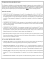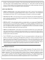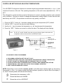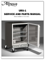
1
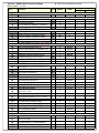
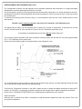
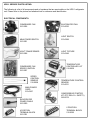
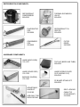
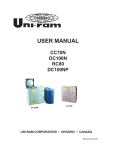
URS-1
SERVICE AND PARTS MANUAL
SERIAL NUMBERS: UP TO 06-10616.
File name: URS-1 Service Manual up to 06-10616
Last revised: Sep. 26th 2007
TROUBLESHOOTING AND SERVICE GUIDE:
The following is intended as a quick service guide designed to diagnose most common problems. It is
intended to be used only as a guideline. Should the unit require actual replacement of components those
must be done by a trained and licensed refrigeration professional. While the unit is within the factory
warranty period, all repairs require prior factory authorization before the work is actually performed.
UNIT NOT COOLING:
•
POWER TO THE UNIT: Is there power to the unit?. Is the voltage within ± 10% of 115 VAC? Low
power conditions affect the amperage draw of the compressor, requiring more amperes on start up. If
the amperage draw is too high, the compressor safety relay could trip leading to component premature failure. if the compressor is tripping on it’s safety relay on startups, the unit will not refrigerate as
required.
•
COMPRESSOR NOT RUNNING: Is the compressor not running when the controller calls for cooling
to begin?. (see point above). Verify that power to the compressor is correct and the starter and safety
relays are working properly.
•
CONDENSR FAN NOT RUNNING: Is the compressor running but not the condenser fan? The condenser fan is on the same circuit as the compressor. They both operate at the same time. Verify that
the condenser fan receives power and the fan blades rotate freely. Verify if there is debris in the
blades that prevents it from starting (ie: leaves, paper, grass clippings, etc…)
•
BACK ON THE UNIT: Is the back cover on the unit?. The back is part of the airflow system to route
the air over the condenser. If the back is removed for cleaning or during installation, it must be placed
back on the unit so it operates correctly.
NOT HOLDING TEMPERATURE CORRECTLY:
•
CONTROL SET POINT: Is the unit operating with the correct set point? Please verify according to
the list provided in the controller programming on the following chapter of this booklet.
•
OPERATING DIFFERENTIAL: The unit operates in a 10 to 15 degree differential on average depending on the quantity of items in the unit. The unit will cycle ON and OFF several times so the
product temperature is an average of the cycle. (see section “Understanding the refrigeration cycle”)
•
DEFROST MODE: Is the unit currently in defrost mode?. The unit defrosts until the coil temperature
reaches 50°F. This is not the temperature of the product, this is just the air temperature during defrost.
•
EVAPORATOR COIL INTAKE: Is the evaporator coil intake blocked by product? For the coil to cool
properly, it must have good air circulation. If the customer has product blocking the air intake such as
soda cans, bottles, loosely wrapped products in plastic bags, etc… these items can block the airflow
to the coil. Without airflow, the cooling performance diminishes quire rapidly preventing cooling and
building ice is the coil further blocking airflow and cooling capacity.
NOISY FAN OPERATION:
•
AMBIENT TEMPERATURE: Is the ambient temperature about 100°F or above? The condenser fan
operates with a temperature controlled speed control in order to minimize noise. If the temperature
surrounding the unit is about 100°F, the unit will operate at full speed to cool the unit as needed.
•
REQUIRED RUN TIME: Is the unit running for too long? As temperature rises and the refrigerator requires cooling the compressor will get hotter requiring further cooling. thus increasing the fan speed
due to excess heat from the unit.
•
RESIDUAL HEAT: Is the unit placed outside in a concrete slab or on a sunny area? Residual heat
that you will have on a hot concrete slab or walkway will in increase condenser fan speed and air is
forced through the condenser coil under the unit. The air going through the intake is next to a hot surface, thus warmed up before entering the unit. Consequently the unit has to work harder to maintain
the proper refrigerating capacity and needs speed up the fan.
•
DEBRIS IN THE BAN BLADE: Is there debris in the condenser fan blade? Not only can debris physically stop the fan blade from rotating (as discussed previously), but is can also block airflow thus preventing the unit for cooling. As the air get hotter in the unit from lack of airflow, the condenser fan will
increase speed to allow more airflow.
•
FULLY STOCKED: Is the unit fully stocked? If the unit is not properly stocked or half empty the unit
will have to work harder. Air does not hold temperature, products do. If there is not product in the refrigerator the unit will turn ON and OFF several times per hour. If the unit is fully stocked, the run-time
will be extended but also the off-time allowing the compressor to cool down properly between cycles.
This will help the unit run more efficiently as several runs per hour will increase compressor temperatures thus requiring the condenser fan to speed up and provide more airflow to cool the unit.
PERFORMANCE ENVELOPE:
The URS-1 has a performance envelop up to 110°F ambient temperature. This means that the unit is
capable of maintaining an internal cabinet temperature between 22°F and 40°F when exposed to 110°F
ambient temperature. The unit will operate without shutting off when the ambient temperature exceeds
100°F in order to maintain the internal cabinet temperature stated above. These peak temperatures occur at least for a few hours a day on hot weather locations and should be considered normal, understanding that the unit will shut down when ambient temperatures return to normal conditions.
CONTROLLER SETTINGS AND ADJUSTING TEMPERATURES :
Your ALFRESCO refrigerator features an exclusive digital programmable thermostat (see figure 1) that
controls all functions of the unit. The operating temperature of the unit is user-adjustable from 15°F to
40°F.
The refrigeration control has been preset at the factory for normal, everyday operation under standard
room conditions. Should you require to change the temperature setting, higher or lower than the standard factory set of 25°F, this procedure can be done very quickly, as follows:
1.
2.
3.
4.
Press the “SET ” button for 1 second to display the set point temperature (25°F) default.
Hold the “SET ” key until the set point starts flashing.
Use the c
key to increase the temperature or d key decrease the temperature.
Press the “SET ” button once more to confirm the value. The display will stop flashing.
Note:
The c “UP” and d “DOWN” keys also serves as indicator lights to show when the
compressor is ON or when the unit is on DEFROST mode.
UP KEY
(Compressor ON
Status Light) see note
See
Note
SET POINT KEY
(Alarm indicator)
see note
DOWN KEY
(Defrost Status Light)
Figure 1
Figure 2
ADJUSTMENTS ITEMS TO REMEMBER:
►
►
►
►
►
►
FOR NORMAL OPERATION SET THE UNIT TO 25°F.
PLEASE NOTE THAT THIS IS NOT THE INTERNAL REFRIGERATOR CABINET TEMPERATURE.
DO NOT CHANGE THE TEMPERATURE SETTING MORE THAN 3°F AT A TIME.
ALLOW 24 HOURS FOR THE REFRIGERATOR TO REACH A NEW TEMPERATURE SETTING.
THE MOTOR WILL START AND STOP OFTEN. THIS IS NORMAL OPERATION.
KEEP YOUR REFRIGERATOR LEVELED.
NOTE: Depending on the controller revision model, it will either have indicator lights on the buttons
themselves (see figure 2) or (newer models) will have indicator symbols on the left side of the display. If
so, these 3 status symbols will indicate the following:
Shows when the compressor is ON
Shows that there is an ALARM
Shows the unit is on DEFROST
OPERATIONAL PARAMETERS
There are two sets of parameters that can be access on this controller. Some require a password,
other do not.
1. Press the “SET ” button for 1 second to display the set point temperature (25°F) default.
2. Hold the “SET ” key for at least 5 seconds once more (the set point starts flashing and after
5
seconds the letters PS will appear on the screen). PS = PASSWORD
3. Release the “SET ” key.
4. At this point, press the “SET ” once more and use the c
or d
keys to reach the number 22
on the screen (this is your password).
5. Press the “SET ” key once more to return the display to “PS”.
6. Use the c
or d
keys to cycle through the different programming parameters.
7. ALWAYS Press the “SET ” button for at lest 5 seconds to exit the programming mode.
Review:
MENU ITEM:
(example:
PS)
PROGRAM:
PRESS
“SET ” KEY
CHANGE ITEM:
c d KEYS
TO CHANGE
CONFIRM:
PRESS
“SET ” KEY
MENU ITEM:
(example:
PS)
Please verify all programmed operational variables according to the list on the following page.
The URS-1 unit should now operate with peak efficiency.
REFRIGERATION:
REFRIGERANT 134A (9OZ)
SUCTION PRESSURE @ TEMP.
18 PSI @ 20°F
ACCEPTABLE RANGE: 12 - 21 PS I (COIL TEMP. 10°F - 24°F)
LIQUID PRESSURE @ TEMP.
125 PSI @ 100°F
170 PSI @ 120°F
ACCEPTABLE RANGE: 125 - 147 PSI (AMBIENT TEMP. 80°F - 90°F)
ACCEPTABLE RANGE: 170 - 197 PSI (AMBIENT TEMP. 100° - 110°F)
Sporlan™ OMNI-Stat® Controller Settings
◄ Values to be changed from default
Model: 952892 - 120 VAC
Code:
Parameter:
Value
Default
UOM
Password
PS
PROBE PARAMETERS
/c
Ambient probe calibration
22
22
#
10
0
°F
15
0
4
~
0
~
1
0
~
PASSWORD
/2
/4
/5
Measurement Stability
19
2
°F
r1
r2
r3
r4
Minimum Allowed Temperature setting
15
-50
°F
Maximum Allowed Temperature setting
40
0
60
°F
0
~
3
3
~
0
0
Minutes
c1
c2
c3
c4
cc
c6
Minimum time between 2 compressor runs
0
0
Minutes
Compressor shut down minimum time
5
0
0
Minutes
0
Minutes
100
4
0
~
4
Hours
2
2
Hours
d0
dI
dt
dP
d4
d5
d6
dd
d8
Defrost type (0=heater / 1=Hot Gas / 2=timed heater /
2
3
~
Defrost interval
6
8
Hours
Defrost Ends Temperature
50
4
°F
Max. Defrost Duration
20
0
30
Minutes
Defrost after power on (0= NO / 1= YES)
0
~
Defrost delay after power on
0
0
Minutes
Block Display during Defrost (0= NO / 1= YES)
1
1
~
Dripping time after defrost
2
2
Minutes
Alarm delay after defrost
Defrost priority over minimum compressor
time (0= NO / 1= YES)
1
1
Hours
0
0
~
Defrost probe - display temperature
~
~
~
0
0
~
0
0
°F
Probe to display (0=ambient / 1=product)
Unit of Measure (0=°C / 1= °F)
REGULATION PARAMETERS
Regulating Differential
rd
Enable Def. alarm when max def. time reached
Automatic variation of set point - NOT USED
COMPRESSOR PARAMETERS
Delay compressor after power on
c0
Compressor Operation minimum time
Compressor Safety (0=OFF / 100=ON)
Continuous Cycle Duration
Alarm Delay after continuous cycle
DEFROST PARAMETERS
d9
d/
dc
Time base for dI and dP (0= hrs / 1= minutes)
ALARM PARAMETERS
Alarm and Fans Differential Temp
A0
AL
AH
Ad
A7
Low temperature alarm (0= OFF)
0
0
°F
Hight temperature alarm (0=OFF)
0
0
°F
Alarm Temperature delay
0
0
Minutes
0
0
Minutes
1
1
~
1=Alarm w/ relay OFF)
1
1
~
0= Disable Buttons / 1=Enable Buttons
1
1
~
Identification for Programming
External Programming
0
~
0
~
~
~
Alarm imput detection delay
OTHER PARAMETERS
Serial Address (communications)
H0
Alarm Relay Operation (0=Alarm w/relay ON -
H1
H2
H5
T
Access
W/O PS
With PS
UNDERSTANDING THE REFRIGERATION CYCLE:
The Refrigeration Controller unit that manages all the refrigerator operations and performance is a rugged and highly
sophisticated commercial grade Sporlan Electronic Controller.
Like all refrigerators, as the unit cools and maintains the desired product temperature, it’s internal temperature will fluctuate between ON and OFF periods depending upon ambient temperature, how many times the door is open and for how
long it’s held open.
To minimize ON (running) times and save energy, it is recommended to open the door for the smallest amount of time
and frequency.
The URS-1 unit is factory preset with a set point of 25°F and with a 19°F differential cycle.
This means that the URS-1 unit will refrigerate until it reaches 25°F internal air temperature. At that point, the unit will
turn OFF and will remain off until it reaches 44°F (Due to the 19°F differential temperature cycle).
It is important to understand that your product will not actually reach 44°F.
The “average” product temperature will settle somewhere midway between the ON and OFF set points (approximately
32°F ~ 35°F) depending on the product type.
Please refer to the following graph for a representation of the refrigeration cycle:
The 19°F differential is used to provide you with the best possible energy savings. A smaller differential would cause the
unit to start and stop several times per hour wasting energy.
The Electronic Temperature Controller in the URS-1 allows the user to change and adjust the default set point (25°F)
between 15°F and 40°F, consequently the product temperature will average lower or higher temperatures as desired.
Please refer to “CONTROLLER SETTINGS” on the following page for adjustments to the set point.
Always remember:
When the door is opened on the URS-1, the display will read the cabinet temperature at that very moment. That is not
your product temperature.
URS-1 SERVICE PARTS LISTING:
The following is a list of all components and or hardware that are serviceable on the URS-1 refrigerator
unit. Please refer to the picture and attached text for reference and identification.
ELECTRICAL COMPONENTS:
CONDENSER FAN
210-0026
MAIN POWER SWITCH
210-0021
LIGHT TRANSFORMER
210-0266
CONDENSER FAN
SPEED CONTROL
210-0027
SPEED
CONTROL
SENSOR
210-0028
EVAPORATOR FAN
210-0025
LIGHT SWITCH
210-0298
LIGHT FIXTURE
210-0249
TEMPERATURE
CONTROLLER KIT
210-0030
TEMPERATURE CONTROL
SENSOR
210-0031
MAIN POWER
CORD
210-0287
COMPRESSOR STARTER
KIT (PTC RELAY + SAFETY)
260-0079
EVAPORATOR
POWER CABLE
210-0020
4 POSITION
TERMINAL BLOCK
210-0301
6 POSITION
TERMINAL BLOCK
210-0302
REFRIGERATION COMPONENTS:
REFRIGERANT
COMPRESSOR
260-0026
EVAPORATOR
COIL
250-0006
CONDENSER
COIL
250-0020
THERMAL EXPANSION
VALVE
220-0002
REFRIGERANT TXV
ORIFICE
220-0009
FILTER
DRIER
220-0029
HARDWARE COMPONENTS:
HINGE (BODY SIDE)
130-1337
HINGE (DOOR SIDE)
130-1338
TOP CAP (BEER LINE TUBE)
290-0082
HINGE SCREW COVER
CLIP (ARROW CLIP)
200-0043
BUSHING (SHOWN)
130-1340
PC BOARD STAND-OFF
290-0009
ADJUSTABLE
HINGE KIT
510-0180
USE ONLY FOR
DOOR REPAIR
SELF LOCKING
CABLE TIE
(PUSH MOUNT)
210-0258
(Hardware components—Cont.)
REPLACEMENT GLASS
FOR LIGHT FIXTURE
210-0286
COMPRESSOR J-BOX
SUPPORT CLIP
260-0044
FRONT LEG
290-0098
REAR WHEEL
290-0091
CONDENSER FAN
FINGER GUARD
210-0267
FOR SERVICE, CALL: 1 866 203 5607
When calling, please provide the following information: model number, serial number and
date of installation, along with a brief description of the problem. The model number and
serial number can be found on a plate located near the top of the inside left wall.