1
13A-1
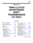
GROUP 13A
MULTIPORT FUEL
INJECTION (MFI)
CONTENTS
GENERAL INFORMATION . . . . . . . .
13A-2
GENERAL SPECIFICATION(S). . . . .
13A-5
SERVICE SPECIFICATION(S) . . . . .
13A-6
SEALANT AND ADHESIVE. . . . . . . .
13A-6
SPECIAL TOOL . . . . . . . . . . . . . . . . .
13A-7
MULTIPORT FUEL INJECTION (MFI)
DIAGNOSIS . . . . . . . . . . . . . . . . . . . .
13A-9
TROUBLESHOOTING STRATEGY . . . . . .
13A-9
DIAGNOSTIC FUNCTION . . . . . . . . . . . . .
13A-9
FAIL-SAFE FUNCTION REFERENCE
TABLE. . . . . . . . . . . . . . . . . . . . . . . . . . . . .
13A-40
DIAGNOSTIC TROUBLE CODE CHART . .
13A-44
SYMPTOM CHART. . . . . . . . . . . . . . . . . . .
13A-48
DIAGNOSTIC TROUBLE CODE
PROCEDURES. . . . . . . . . . . . . . . . . . . . . .
13A-51
SYMPTOM PROCEDURES . . . . . . . . . . . . 13A-737
DATA LIST REFERENCE TABLE . . . . . . . 13A-852
GENERAL SCAN TOOL (GST) MODE 01
REFERENCE TABLE . . . . . . . . . . . . . . . . . 13A-866
ACTUATOR TEST REFERENCE TABLE. . 13A-871
CHECK AT THE ENGINE CONTROL MODULE
(ECM) . . . . . . . . . . . . . . . . . . . . . . . . . . . . . 13A-872
INSPECTION PROCEDURE USING AN
OSCILLOSCOPE . . . . . . . . . . . . . . . . . . . . 13A-881
ON-VEHICLE SERVICE. . . . . . . . . . . 13A-891
COMPONENT LOCATION . . . . . . . . . . . . . 13A-891
THROTTLE BODY (THROTTLE VALVE AREA)
CLEANING . . . . . . . . . . . . . . . . . . . . . . . . . 13A-897
FUEL PRESSURE TEST . . . . . . . . . . . . . . 13A-897
FUEL PUMP CONNECTOR DISCONNECTION
(HOW TO REDUCE PRESSURIZED FUEL
PRESSURE) . . . . . . . . . . . . . . . . . . . . . . . . 13A-901
FUEL PUMP OPERATION CHECK . . . . . . 13A-901
MULTIPORT FUEL INJECTION (MFI) RELAY
CONTINUITY CHECK . . . . . . . . . . . . . . . . . 13A-903
FUEL PUMP RELAY CONTINUITY
CHECK . . . . . . . . . . . . . . . . . . . . . . . . . . . . 13A-903
INJECTOR RELAY CONTINUITY CHECK . 13A-905
THROTTLE ACTUATOR CONTROL MOTOR
RELAY CONTINUITY CHECK . . . . . . . . . . 13A-905
FUEL PUMP CIRCUIT RESISTOR CHECK 13A-906
INTAKE AIR TEMPERATURE SENSOR
CHECK . . . . . . . . . . . . . . . . . . . . . . . . . . . . 13A-906
ENGINE COOLANT TEMPERATURE
SENSOR CHECK . . . . . . . . . . . . . . . . . . . . 13A-907
HEATED OXYGEN SENSOR CHECK . . . . 13A-908
INJECTOR CHECK . . . . . . . . . . . . . . . . . . . 13A-910
THROTTLE ACTUATOR CONTROL MOTOR
CHECK . . . . . . . . . . . . . . . . . . . . . . . . . . . . 13A-911
ENGINE OIL CONTROL VALVE CHECK . . 13A-912
EVAPORATIVE EMISSION VENTILATION
SOLENOID CHECK . . . . . . . . . . . . . . . . . . 13A-913
EVAPORATIVE EMISSION PURGE
SOLENOID CHECK . . . . . . . . . . . . . . . . . . 13A-913
INJECTOR . . . . . . . . . . . . . . . . . . . . . 13A-914
REMOVAL AND INSTALLATION . . . . . . . . 13A-914
THROTTLE BODY ASSEMBLY . . . . . 13A-918
REMOVAL AND INSTALLATION . . . . . . . . 13A-918
ENGINE CONTROL RESISTOR. . . . . 13A-919
REMOVAL AND INSTALLATION . . . . . . . . 13A-919
ENGINE CONTROL MODULE
(ECM) . . . . . . . . . . . . . . . . . . . . . . . . . 13A-920
REMOVAL AND INSTALLATION . . . . . . . . 13A-920
13A-2
MULTIPORT FUEL INJECTION (MFI)
GENERAL INFORMATION
GENERAL INFORMATION
.
The Multiport Fuel Injection System consists of sensors which detect the engine conditions, the ENGINE
CONTROL MODULE (ECM) which controls the system based on signals from these sensors, and actuators which operate under the control of the ECM.
The ECM carries out activities such as fuel injection
control, idle air control, and ignition timing control.
In addition, the ECM is equipped with several diagnostic test modes which simplify troubleshooting
when a problem develops.
.
FUEL INJECTION CONTROL
The injector drive times and injection timing are controlled so that the optimum air/fuel mixture is supplied to the engine to correspond to the
continually-changing engine operation conditions.
A single injector is mounted at the intake port of each
cylinder. Fuel is sent under pressure from the fuel
tank to the fuel injectors by the fuel pump, with the
pressure being regulated by the fuel pressure regulator. The regulated fuel is distributed to each of the
injectors.
Fuel injection is normally carried out once for each
cylinder for every two rotations of the crankshaft.
The firing order is 1-3-4-2. Each cylinder has a dedicated fuel injector. This is called multiport.
The ECM provides a richer air/fuel mixture by carrying out "open-loop" control when the engine is cold
or operating under high load conditions in order to
maintain engine performance.In addition, when the
engine is under normal operating temperature after
warming-up, the ECM controls the air/fuel mixture by
using the heated oxygen sensor signal to carry out
"closed-loop" control. The closed-loop control
achieves the theoretical air/fuel mixture ratio where
the catalytic converter can obtain the maximum
cleaning performance.
IDLE AIR CONTROL
The idle speed is kept at the optimum speed by controlling the amount of air that passes through the
throttle valve in accordance with changes in idling
conditions and engine load during idling.
The ECM drives the throttle actuator control motor to
keep the engine running at the pre-set idle target
speed in accordance with the engine coolant temperature and A/C and other electrical load. In addition,
when the air conditioning switch is turned off and on
while the engine is idling, the throttle actuator control
motor adjusts the throttle valve pass-through air
amount according to the engine load conditions to
avoid fluctuations in the engine speed.
.
IGNITION TIMING CONTROL
The ignition power transistor located in the ignition
primary circuit turns ON and OFF to control the primary current flow to the ignition coil. This controls the
ignition timing to provide the optimum ignition timing
with respect to the engine operating conditions. The
ignition timing is determined by the ECM from engine
speed, intake air volume, engine coolant temperature, and atmospheric pressure.
.
DIAGNOSTIC TEST MODE
• When a fault is detected in one of the sensors or
actuators related to emission control, the Malfunction Indicator Lamp (SERVICE ENGINE
SOON or Check Engine Lamp) illuminates to
warn the driver.
• When a fault is detected in one of the sensors or
actuators, a diagnostic trouble code corresponding to the fault is stored in the ECM.
• The RAM data inside the ECM that is related to
the sensors and actuators can be read with the
scan tool. In addition, the actuators can be controlled by scan tool MB991958 (M.U.T.-III sub
assembly) under certain circumstances.
.
THROTTLE VALVE OPENING CONTROL
This system electrically controls the opening of the
throttle valve. The ECM detects the amount of travel
of the accelerator pedal via the accelerator pedal
position sensor, and controls the actuation of the
throttle actuator control motor, which is mounted on
the throttle body, in order to attain the target throttle
valve opening that has been predetermined in accordance with driving conditions.
TSB Revision
M1131000103669
.
.
MULTIPORT FUEL INJECTION (MFI)
GENERAL INFORMATION
OTHER CONTROL FUNCTIONS
Fuel Pump Control
• Turns the fuel pump relay ON so that current is
supplied to the fuel pump while the engine is
cranking or running.
• In accordance with the driving conditions,
switches the actuation condition of the fuel pump.
A/C Compressor Clutch Relay Control
• Turns the compressor clutch of the A/C ON and
OFF.
Engine Oil Control Valve Control
• The ECM carries out the duty control of the
engine oil control valve according to the operation condition. This varies the phase angle of the
camshaft to optimize the valve timing.
TSB Revision
13A-3
Intake Charge Pressure Control
• Control the intake charge pressure by controlling
the duty of the turbocharger wastegate solenoid.
Generator Output Current Control
• Prevent generator output current from increasing
suddenly and idle speed from dropping at times
such as when the headlights are turned on.
Evaporative Emission Purge Control
• (Refer to GROUP 17, Emission Control −Evaporative Emission Control System −General Information P.17-74.)
13A-4
MULTIPORT FUEL INJECTION (MFI)
GENERAL INFORMATION
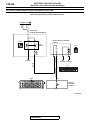
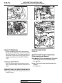
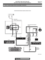
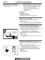
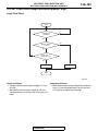
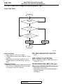
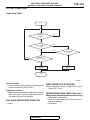
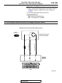
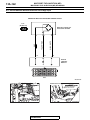
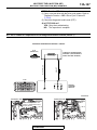
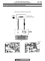
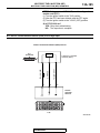
MULTIPORT FUEL INJECTION (MFI) SYSTEM DIAGRAM
Decide
Sense
1 Mass airflow sensor
2 Intake air temperature sensor 1
3 Throttle position sensor (main)
4 Throttle position sensor (sub)
5 Manifold absolute pressure sensor
6 Intake air temperature sensor 2
7 Engine coolant temperature sensor
8 Intake camshaft position sensor
9 Exhaust camshaft position sensor
10 Crankshaft position sensor
11 Knock sensor
12 Heated oxygen sensor (front)
13 Heated oxygen sensor (rear)
14 Fuel tank differential pressure sensor
15 Fuel tank temperature sensor
Accelerator pedal position sensor (main)
Accelerator pedal position sensor (sub)
Engine oil pressure switch
Power steering pressure switch
Generator FR terminal
Generator L terminal
Clutch pedal position switch <M/T>
Ignition switch-IG
Ignition switch-ST
Power supply
CAN communication (input signal)
Act
ECM
(with barometric
pressure sensor)
1
2
3
4
5
6
Intake engine oil control valve
Exhaust engine oil control valve
Throttle actuator control motor
Injector
Evaporative emission purge solenoid
Evaporative emission ventilation
solenoid
7 Turbocharger wastegate solenoid 1
8 Turbocharger wastegate solenoid 2
Ignition coil, ignition power transistor
Multiport fuel injection (MFI) relay
Fuel pump relay 1
Fuel pump relay 2
Starter relay
Throttle actuator control motor relay
Generator G terminal
Heated oxygen sensor heater
A/C compressor relay
CAN communication (output signal)
3 Throttle position sensor (main)
4 Throttle position sensor (sub)
3 Throttle actuator control motor
5 Evaporative emission
purge solenoid
Bypass valve
5 Manifold
absolute
pressure
sensor
Check valve
1 Mass airflow sensor
2 Intake air
temperature
sensor 1
Fuel
pressure
regulator
To fuel
tank
1 Intake engine
oil control valve
6 Intake air
temperrature
sensor 2
8
Intake camshaft
position sensor
2
Exhaust engine
oil control valve
14 Fuel tank
differential
puressure
sensor
4 Injector
Evaporative
emission
canister
7 Engine coolant
temperature sensor
Air
inlet
Fuel tank
Fuel pump
Fuel
level
11 Knock sensor 6 Evaporative
sensor
emission
ventilation
solenoid
15 Fuel tank
temperature
10 Crankshaft position sensor
sensor
9 Exhaust camshaft position sensor
Turbocharger
wastegate actuator
7 Turbocharger
wastegate solenoid 1
8 Turbocharger
wastegate solenoid 2
12 Heated oxygen sensor (front)
13 Heated oxygen sensor (rear)
AK703839 AB
NOTE: For the vacuum routing, refer to GROUP 17, Emission Control −Vacuum Hoses −Vacuum Hose Routing P.17-70.
TSB Revision
MULTIPORT FUEL INJECTION (MFI)
GENERAL SPECIFICATIONS
GENERAL SPECIFICATIONS
ITEMS
Throttle body
Engine control
module (ECM)
Sensors
Actuators
Fuel pressure
regulator
Throttle bore mm (in.)
Throttle position sensor
Throttle actuator control motor
Identification model No.
Mass airflow sensor
Barometric pressure sensor
Intake air temperature sensor 1
Intake air temperature sensor 2
Engine coolant temperature sensor
Heated oxygen sensor
Accelerator pedal position sensor
Camshaft position sensor
Crankshaft position sensor
Knock sensor
Power steering pressure switch
Manifold absolute pressure sensor
Clutch pedal position switch <M/T>
Multiport fuel injection (MFI) relay
Fuel pump relay
Throttle actuator control motor relay
Injector type and number
Injector identification mark
Engine oil control valve
Evaporative emission purge solenoid
Turbocharger wastegate solenoid
Regulator pressure kPa (psi)
TSB Revision
SPECIFICATIONS
60 (2.36)
Hall element type
DC motor type, having brushes
E6T72671 <M/T>
E6T72672 <TC-SST>
Heat sensitizing type
Semi
conductor type
Thermistor type
Thermistor type
Thermistor type
Zirconia type
Hall element type
Magneto resistance element type
Magneto resistance element type
Piezoelectric type
Contact switch type
Semiconductor type
Contact switch type
Contact switch type
Contact switch type
Contact switch type
Electromagnetic type, 4
JME600G
Duty cycle type solenoid valve
Duty cycle type solenoid valve
Duty cycle type solenoid valve
329 (48)
13A-5
M1131000201240
13A-6
MULTIPORT FUEL INJECTION (MFI)
SERVICE SPECIFICATIONS
SERVICE SPECIFICATIONS
ITEMS
Fuel pressure kPa (psi)
M1131000302154
STANDARD VALUE
310 −345 (45 −50) at curb idle
Intake air temperature sensor 1 resistance
kΩ
Vacuum hose
disconnected
Vacuum hose connected Approximately 260 (38) at curb
idle
13 −17
−20° C (−4° F)
0° C (32° F)
20° C (68° F)
40° C (104° F)
60° C (140° F)
80° C (176° F)
Intake air temperature sensor 2 resistance
kΩ
−20° C (−4° F)
0° C (32° F)
20° C (68° F)
40° C (104° F)
60° C (140° F)
80° C (176° F)
Engine coolant temperature sensor
resistance kΩ
−20° C (−4° F)
0° C (32° F)
20° C (68° F)
40° C (104° F)
60° C (140° F)
80° C (176° F)
Heated oxygen sensor output voltage V
Heated oxygen sensor heater resistance Ω
Front
Rear
Injector coil resistance Ω
Throttle actuator control motor coil resistance Ω
Fuel pump circuit resistor resistance Ω
Intake engine oil control valve coil resistance Ω
Exhaust engine oil control valve coil resistance Ω
5.4 −6.6
2.3 −3.0
1.0 −1.5
0.56 −0.76
0.31 −0.43
13 −18
5.1 −6.9
2.0 −3.0
0.9 −1.5
0.40 −0.78
0.23 −0.42
14 −17
5.1 −6.5
2.1 −2.7
0.9 −1.3
0.48 −0.68
0.26 −0.36
0.6 −1.0
4.5 −8.0
4.5 −8.0
10.5 −13.5 [at 20° C (68° F)]
0.3 −80 [at 20° C (68° F)]
0.45 −0.65 [at 20° C (68° F)]
6.9 −7.9 [at 20° C (68° F)]
6.9 −7.9 [at 20° C (68° F)]
SEALANT AND ADHESIVE
M1131000501490
ITEM
SPECIFIED SEALANT
Engine coolant temperature sensor threaded portion LOCTITE 262, Three bond 1324N or equivalent
TSB Revision
MULTIPORT FUEL INJECTION (MFI)
SPECIAL TOOL
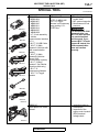
SPECIAL TOOL
Tool
A
MB991824
B
MB991827
C
MB991910
D
DO NOT USE
MB991911
E
DO NOT USE
MB991914
13A-7
M1131000602520
Tool number and name
MB991958
A: MB991824
B: MB991827
C: MB991910
D: MB991911
E: MB991914
F: MB991825
G: MB991826
M.U.T.-III sub assembly
A: Vehicle
Communication Interface
(V.C.I.)
B: M.U.T.-III USB Cable
C: M.U.T.-III Main
Harness A (Vehicles with
CAN communication
system)
D: M.U.T.-III Main
Harness B (Vehicles
without CAN
communication system)
E: M.U.T.-III Main
Harness C (for Daimler
Chrysler models only)
F: M.U.T.-III
Measurement Adapter
G: M.U.T.-III Trigger
Harness
Supersession
Application
MB991824-KIT
• Reading diagnostic
trouble code
NOTE: G: MB991826
•
MFl system inspection
M.U.T.-III Trigger
Harness is not necessary • Measurement of fuel
pressure
when pushing V.C.I.
ENTER key.
CAUTION
For vehicles with CAN
communication, use
M.U.T.-III main harness
A to send simulated
vehicle speed. If you
connect M.U.T.-III main
harness B instead, the
CAN communication
does not function
correctly.
MB992110
Power plant ECU check
harness
−
F
MB991825
G
MB991826
MB991958
MB992110
TSB Revision
• Inspection using an
oscilloscope
• Inspection of the
engine control module
(ECM) terminal
voltage check
13A-8
MULTIPORT FUEL INJECTION (MFI)
SPECIAL TOOL
Tool
Tool number and name
MB991709
Test harness
Supersession
MB991709-01
Application
Inspection using an
oscilloscope
MB991658
Test harness
Tool not available
MB992049
MB992049-01
• Inspection using an
oscilloscope
• Inspection of throttle
position sensor
• Inspection of heated
oxygen sensor
• Inspection of engine
oil control valve
Measurement of fuel
pressure
MB992001
Hose adaptor
Measurement of fuel
pressure
MB991981
Fuel pressure gauge set
Tool not available
Measurement of fuel
pressure
MB992076
Injector test set
Measurement of fuel
pressure
MB992042
Engine coolant
temperature sensor
wrench
−
Removal and installation
of the engine coolant
temperature sensor
MB992106
O-ring installer
−
Installation of O-ring on
injector injection nozzle
side
MB991658
MB992049
MB992001
MB991981
MB992076
MB992042
TSB Revision
13A-9
MULTIPORT FUEL INJECTION (MFI)
MULTIPORT FUEL INJECTION (MFI) DIAGNOSIS
MULTIPORT FUEL INJECTION (MFI) DIAGNOSIS
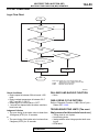
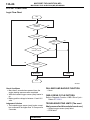
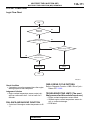
TROUBLESHOOTING STRATEGY
M1131150002188
NOTE: If a DTC is erased, its "freeze frame" data will
also be erased and system readiness test status will
be reset. Store the "freeze frame" data before erasing the DTC.
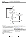
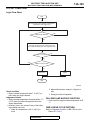
Use these steps to plan your diagnostic strategy. If
you follow them carefully, you will be sure to have
exhausted most of the possible ways to find an MFI
fault.
1. Gather as much information as possible about the
complaint from the customer.
2. Verify that the condition described by the
customer exists.
3. Check the vehicle for any MFI Diagnostic Trouble
Code (DTC).
4. If you cannot verify the condition and there are no
DTCs, the malfunction is intermittent. For
information on how to cope with intermittent
malfunctions, refer to GROUP 00, How to Use
Troubleshooting/Inspection Service Points −How
to Cope with Intermittent Malfunctions P.00-15.
5. If you can verify the condition but there are no
DTCs, or the system cannot communicate with
the scan tool, refer to the trouble symptom
classification table.
DIAGNOSTIC FUNCTION
6. If there is a DTC, store the number of the code,
then erase the code from the memory using the
scan tool.
7. Reconfirm the malfunction symptom and carry out
a test drive with the drive cycle pattern.
8. If DTC is set again, carry out an inspection with
appropriate diagnostic trouble code procedures.
9. If DTC is not set again, the malfunction is
intermittent. For information on how to cope with
intermittent malfunctions, refer to GROUP 00,
How to Use Troubleshooting/Inspection Service
Points −How to Cope with Intermittent
Malfunctions P.00-15.
10.After repairs are completed, conduct a road test
duplicating the complaint set conditions to confirm
the malfunction has been corrected.
NOTE: If the engine control module (ECM) is
replaced, Immobilizer Encrypted Code Registration
should be carried out, refer to GROUP 42B, ID Code
Registration Necessity Judgment Table <Vehicles
with KOS> P.42B-12 or GROUP 42C, ID Codes
Registration Judgment Table <Vehicles with WCM>
P.42C-9.
M1131155502586
.
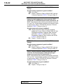
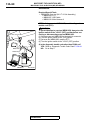
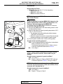
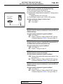
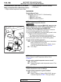
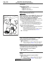
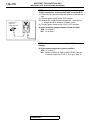
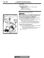
MALFUNCTION INDICATOR LAMP (SERVICE
ENGINE SOON OR CHECK ENGINE LAMP)
Malfunction
indicator lamp
(SERVICE
ENGINE
SOON or check
engine lamp)
AK704069AC
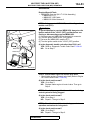
Among the on-board diagnostic items, Malfunction Indicator
Lamp (SERVICE ENGINE SOON or Check Engine Lamp) illuminates to notify the driver of an emission control malfunction.
However, when an irregular signal returns to normal and the
engine control module judges that it has returned to normal, the
Malfunction Indicator Lamp (SERVICE ENGINE SOON or
Check Engine Lamp) will switch off.
Immediately after the ignition switch is turned on, the Malfunction Indicator Lamp (SERVICE ENGINE SOON or Check
Engine Lamp) is lit for 20 seconds to indicate that the Malfunction Indicator Lamp (SERVICE ENGINE SOON or Check
Engine Lamp) operates normally.
NOTE: When the Transmission Control Module (TCM) detects
malfunctions related to the TC-SST, the Malfunction indicator
Lamp (SERVICE ENGINE SOON or Check Engine Lamp) is
also illuminated.
.
TSB Revision
13A-10
MULTIPORT FUEL INJECTION (MFI)
MULTIPORT FUEL INJECTION (MFI) DIAGNOSIS
Items Indicated by the Malfunction Indicator Lamp
(SERVICE ENGINE SOON or Check Engine Lamp)
DTC
P0011
P0014
P0016
P0017
P0031
P0032
P0037
P0038
P0069
P0096*
P0097*
P0098*
P0101*
P0102*
P0103*
P0106
P0107
P0108
P0111*
P0112*
P0113*
P0116*
P0117*
P0118*
P0122*
P0123*
P0125*
P0128
P0131
P0132
P0133
P0134*
P0137
P0138
P0139
P0140
P0171
P0172
P0181
P0182
P0183
ITEM
Intake variable valve timing system target error
Exhaust variable valve timing system target error
Crankshaft/camshaft (intake) position sensor phase problem
Crankshaft/camshaft (exhaust) position sensor phase problem
Heated oxygen sensor (front) heater circuit low
Heated oxygen sensor (front) heater circuit high
Heated oxygen sensor (rear) heater circuit low
Heated oxygen sensor (rear) heater circuit high
Abnormal correlation between manifold absolute pressure sensor and barometric pressure
sensor
Intake air temperature circuit range/performance problem (sensor 2)
Intake air temperature circuit low input (sensor 2)
Intake air temperature circuit high input (sensor 2)
Mass airflow circuit range/performance problem
Mass airflow circuit low input
Mass airflow circuit high input
Manifold absolute pressure circuit range/performance problem
Manifold absolute pressure circuit low input
Manifold absolute pressure circuit high input
Intake air temperature circuit range/performance problem (sensor 1)
Intake air temperature circuit low input (sensor 1)
Intake air temperature circuit high input (sensor 1)
Engine coolant temperature circuit range/performance problem
Engine coolant temperature circuit low input
Engine coolant temperature circuit high input
Throttle position sensor (main) circuit low input
Throttle position sensor (main) circuit high input
Insufficient coolant temperature for closed loop fuel control
Coolant thermostat (coolant temperature below thermostat regulating temperature)
Heated oxygen sensor (front) circuit low voltage
Heated oxygen sensor (front) circuit high voltage
Heated oxygen sensor (front) circuit slow response
Heated oxygen sensor (front) circuit no activity detected
Heated oxygen sensor (rear) circuit low voltage
Heated oxygen sensor (rear) circuit high voltage
Heated oxygen sensor (rear) circuit slow response
Heated oxygen sensor (rear) circuit no activity detected
System too lean
System too rich
Fuel tank temperature sensor circuit range/performance
Fuel tank temperature sensor circuit low input
Fuel tank temperature sensor circuit high input
TSB Revision
MULTIPORT FUEL INJECTION (MFI)
MULTIPORT FUEL INJECTION (MFI) DIAGNOSIS
DTC
P0201
P0202
P0203
P0204
P0222*
P0223*
P0234
P0243
P0247
P0300
P0301
P0302
P0303
P0304
P0327
P0328
P0335*
P0340*
P0365*
P0420
P0441
P0442
P0443
P0446
P0450
P0451
P0452
P0453
P0455
P0456
P0461
P0462
P0463
P0500*
P0506
P0507
P0551
P0554
P0603*
P0606*
P0630*
P0638*
P0642*
P0657*
ITEM
Injector circuit −cylinder 1
Injector circuit −cylinder 2
Injector circuit −cylinder 3
Injector circuit −cylinder 4
Throttle position sensor (sub) circuit low input
Throttle position sensor (sub) circuit high input
Turbocharger wastegate system malfunction
Turbocharger wastegate solenoid 1 circuit
Turbocharger wastegate solenoid 2 circuit
Random/multiple cylinder misfire detected
Cylinder 1 misfire detected
Cylinder 2 misfire detected
Cylinder 3 misfire detected
Cylinder 4 misfire detected
Knock sensor circuit low
Knock sensor circuit high
Crankshaft position sensor circuit
Intake camshaft position sensor circuit
Exhaust camshaft position sensor circuit
Warm up catalyst efficiency below threshold
Evaporative emission control system incorrect purge flow
Evaporative emission control system leak detected (small leak)
Evaporative emission purge solenoid circuit
Evaporative emission ventilation solenoid circuit
Fuel tank differential pressure sensor malfunction
Fuel tank differential pressure circuit range/performance problem
Fuel tank differential pressure circuit low input
Fuel tank differential pressure circuit high input
Evaporative emission control system leak detected (gross leak)
Evaporative emission control system leak detected (very small leak)
Fuel level sensor (main) circuit range/performance
Fuel level sensor circuit low input
Fuel level sensor circuit high input
Vehicle speed signal malfunction
Idle control system RPM lower than expected
Idle control system RPM higher than expected
Power steering pressure switch circuit range/performance
Power steering pressure switch circuit intermittent
EEPROM malfunction
Engine control module main processor malfunction
Vehicle Identification Number (VIN) malfunction
Throttle actuator control motor circuit range/performance
Throttle position sensor power supply
Throttle actuator control motor relay circuit malfunction
TSB Revision
13A-11
13A-12
DTC
P1021
P1025
P1233*
P1234*
P1235*
P1236*
P1237*
P1238*
P1239*
P1241*
P1320
P1506
P1507
P1590*
P1603*
P1676*
P2066
P2100*
P2101*
P2122*
P2123*
P2127*
P2128*
P2135*
P2138*
P2195
P2228*
P2229*
P2252
P2253
U0101*
U0121*
U0141*
U1180*
MULTIPORT FUEL INJECTION (MFI)
MULTIPORT FUEL INJECTION (MFI) DIAGNOSIS
ITEM
Intake engine oil control valve circuit
Exhaust engine oil control valve circuit
Throttle position sensor (main) plausibility
Throttle position sensor (sub) plausibility
Mass airflow sensor plausibility
A/D converter
Accelerator pedal position sensor plausibility
Mass airflow sensor plausibility (torque monitor)
Engine RPM plausibility
Torque monitor
Ignition timing retard insufficient
Idle control system RPM lower than expected at low temperature
Idle control system RPM higher than expected at low temperature
TCM to ECM communication error in torque reduction request <TC-SST>
Battery backup circuit malfunction
Variant coding
Fuel level sensor (sub) circuit range/performance
Throttle actuator control motor circuit (open)
Throttle actuator control motor magneto malfunction
Accelerator pedal position sensor (main) circuit low input
Accelerator pedal position sensor (main) circuit high input
Accelerator pedal position sensor (sub) circuit low input
Accelerator pedal position sensor (sub) circuit high input
Throttle position sensor (main and sub) range/performance problem
Accelerator pedal position sensor (main and sub) range/performance problem
Heated oxygen sensor (front) inactive
Barometric pressure circuit low input
Barometric pressure circuit high input
Heated oxygen sensor offset circuit low voltage
Heated oxygen sensor offset circuit high voltage
TC-SST-ECU time-out <TC-SST>
ASC-ECU time-out
ETACS-ECU time-out
Combination meter time-out
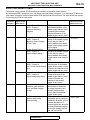
NOTE: If the Malfunction Indicator Lamp (SERVICE ENGINE SOON or Check Engine Lamp) illuminates
because of a malfunction of the engine control module (ECM), communication between the scan tool
MB991958 (M.U.T.-III sub assembly) and the ECM is impossible. In this case, the diagnostic trouble code
cannot be read.
NOTE: After the ECM has detected a malfunction, the Malfunction Indicator Lamp (SERVICE ENGINE
SOON or Check Engine Lamp) illuminates when the engine is next turned on and the same malfunction is
re-detected. However, for items marked with a "*" in the DTC NO. column, the Malfunction Indicator Lamp
(SERVICE ENGINE SOON or Check Engine Lamp) illuminates only on the first detection of the malfunction.
NOTE: After the Malfunction Indicator Lamp (SERVICE ENGINE SOON or Check Engine Lamp) illuminates,
it will be switched off under the following conditions.
TSB Revision
MULTIPORT FUEL INJECTION (MFI)
MULTIPORT FUEL INJECTION (MFI) DIAGNOSIS
13A-13
• When the ECM monitored the powertrain malfunction three times* and met set condition requirements, it
detected no malfunction. *: In this case, "one time" indicates from engine start to next engine start.
• For misfiring or a fuel trim malfunction, when driving conditions (engine speed, engine coolant temperature, etc.) are similar to those when the malfunction was first recorded.
• The illuminated MIL for the vehicle identification number related faults is extinguished when the vehicle
identification number is detected.
NOTE: Sensor 1 of the heated oxygen sensor indicates the sensor mounted at a position closest to the
engine, and sensor 2 of the heated oxygen sensor indicates the sensor mounted at the position second closest to the engine.
TSB Revision
13A-14
MULTIPORT FUEL INJECTION (MFI)
MULTIPORT FUEL INJECTION (MFI) DIAGNOSIS
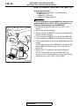
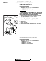
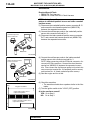
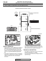
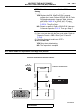
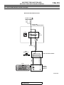
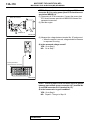
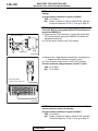
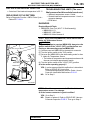
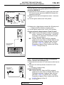
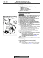
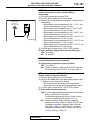
HOW TO CONNECT THE SCAN TOOL (M.U.T.-III)
Required Special Tools:
• MB991958: Scan Tool (M.U.T.-III Sub Assembly)
• MB991824: V.C.I.
• MB991827: USB Cable
• MB991910: Main Harness A
CAUTION
To prevent damage to scan tool MB991958, always turn the
ignition switch to the "LOCK" (OFF) position before connecting or disconnecting scan tool MB991958.
1. Ensure that the ignition switch is at the "LOCK" (OFF)
position.
2. Start up the personal computer.
3. Connect special tool MB991827 to special tool MB991824
and the personal computer.
4. Connect special tool MB991910 to special tool MB991824.
5. Connect special tool MB991910 to the data link connector.
6. Turn the power switch of special tool MB991824 to the "ON"
position.
NOTE: When the special tool MB991824 is energized, special tool MB991824 indicator light will be illuminated in a
green color.
7. Start the M.U.T.-III system on the personal computer.
NOTE: Disconnecting the scan tool MB991958 is the
reverse of the connecting sequence, making sure that the
ignition switch is at the "LOCK" (OFF) position.
Data link connector
MB991910
MB991824
MB991827
AC608435 AB
TSB Revision
MULTIPORT FUEL INJECTION (MFI)
MULTIPORT FUEL INJECTION (MFI) DIAGNOSIS
13A-15
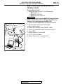
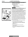
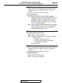
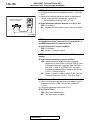
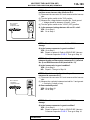
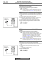
HOW TO READ AND ERASE DIAGNOSTIC
TROUBLE CODES.
Required Special Tools:
• MB991958: Scan Tool (M.U.T.-III Sub Assembly)
• MB991824: V.C.I.
• MB991827: USB Cable
• MB991910: Main Harness A
CAUTION
To prevent damage to scan tool MB991958, always turn the
ignition switch to the "LOCK" (OFF) position before connecting or disconnecting scan tool MB991958.
1. Connect scan tool MB991958 to the data link connector.
2. Turn the ignition switch to the "ON" position.
3. Select "System select."
4. Choose "from 2006 MY" under "MODEL YEAR".
5. Check that "Vehicle Information" contents are correct.
6. Choose "MFI".
7. Select "Diagnostic Trouble Code"
8. If a DTC is set, it is shown.
9. Choose "Erase DTCs" to erase the DTC.
Data link connector
MB991910
MB991824
MB991827
AC608435 AB
TSB Revision
13A-16
MULTIPORT FUEL INJECTION (MFI)
MULTIPORT FUEL INJECTION (MFI) DIAGNOSIS
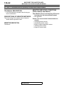
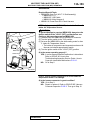
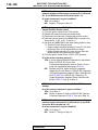
HOW TO READ DATA LIST
Required Special Tools:
• MB991958: Scan Tool (M.U.T.-III Sub Assembly)
• MB991824: V.C.I.
• MB991827: USB Cable
• MB991910: Main Harness A
CAUTION
To prevent damage to scan tool MB991958, always turn the
ignition switch to the "LOCK" (OFF) position before connecting or disconnecting scan tool MB991958.
1. Connect scan tool MB991958 to the data link connector.
2. Turn the ignition switch to the "ON" position.
3. Select "System select."
4. Choose "from 2006 MY" under "MODEL YEAR".
5. Check that "Vehicle Information" contents are correct.
6. Choose "MFI".
7. Select "Data List."
8. Choose an appropriate item and select the "OK" button.
Data link connector
MB991910
MB991824
MB991827
AC608435 AB
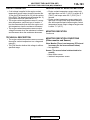
HOW TO PERFORM ACTUATOR TEST
Required Special Tools:
• MB991958: Scan Tool (M.U.T.-III Sub Assembly)
• MB991824: V.C.I.
• MB991827: USB Cable
• MB991910: Main Harness A
TSB Revision
MULTIPORT FUEL INJECTION (MFI)
MULTIPORT FUEL INJECTION (MFI) DIAGNOSIS
13A-17
CAUTION
To prevent damage to scan tool MB991958, always turn the
ignition switch to the "LOCK" (OFF) position before connecting or disconnecting scan tool MB991958.
1. Connect scan tool MB991958 to the data link connector.
2. Turn the ignition switch to the "ON" position.
3. Select "System select."
4. Choose "from 2006 MY" under "MODEL YEAR".
5. Check that "Vehicle Information" contents are correct.
6. Choose "MFI".
7. Select "Actuator Test."
8. Choose an appropriate item and select the "OK" button.
Data link connector
MB991910
MB991824
MB991827
AC608435 AB
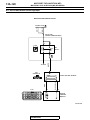
HOW TO DIAGNOSE THE CAN BUS LINES
Required Special Tools:
• MB991958: Scan Tool (M.U.T.-III Sub Assembly)
• MB991824: V.C.I.
• MB991827: USB Cable
• MB991910: Main Harness A
TSB Revision
13A-18
MULTIPORT FUEL INJECTION (MFI)
MULTIPORT FUEL INJECTION (MFI) DIAGNOSIS
Data link connector
MB991910
MB991824
MB991827
AC608435 AB
CAUTION
To prevent damage to scan tool MB991958, always turn the
ignition switch to the "LOCK" (OFF) position before connecting or disconnecting scan tool MB991958.
1. Connect scan tool MB991958 to the data link connector.
2. Turn the ignition switch to the "ON" position.
3. Select "CAN bus diagnosis" from the start-up screen.
4. When the vehicle information is displayed, confirm that it
matches the vehicle whose CAN bus lines will be
diagnosed.
• If they matches, go to step 8.
• If not, go to step 5.
5. Select the "view vehicle information" button.
6. Enter the vehicle information and select the "OK" button.
7. When the vehicle information is displayed, confirm again
that it matches the vehicle whose CAN bus lines will be
diagnosed.
• If they matches, go to step 8.
• If not, go to step 5.
8. Select the "OK" button.
9. When the optional equipment screen is displayed, choose
the one which the vehicle is fitted with, and then select the
"OK" button.
PROVISIONAL DTCs [OBD-II Test Mode - Results
(Mode 7)]
The general scan tool will display the Provisional DTCs
reported by ECM if the ECM detects some malfunction for "Misfire", "Fuel System" and "Comprehensive" monitoring during a
SINGLE Driving Cycle. The intended use of this data is to
assist the technician after a vehicle repair, and after clearing
diagnostic information, by reporting test result after a SINGLE
Driving Cycle. Note that the test results reported by this mode
do not necessarily indicate a faulty component/system. If test
results indicate a failure after ADDITIONAL (consecutive) driving, then the Malfunction Indicator Lamp (SERVICE ENGINE
SOON or Check Engine Lamp) will be illuminated and a DTC
will set.
TSB Revision
MULTIPORT FUEL INJECTION (MFI)
MULTIPORT FUEL INJECTION (MFI) DIAGNOSIS
13A-19
MODE 6 REFERENCE TABLE
The engine control module (ECM) monitors the condition of emission control system.
By selecting MODE 6 using scan tool, Test Result and Limit Value (minimum) *1 or (maximum) *2 about the
main items of emission control system which ECM monitors can be confirmed. The value at the last monitoring is output by ECM as a test result.
ON-BOARD
DIAGNOSTIC
MONITOR ID
STANDARDIZED / MONITORING ITEM
MANUFACTURER
DEFIND TEST ID
01
81
02
08
82
05
88
21
83
39
85
Oxygen Sensor Monitor
Bank 1 −Sensor 1
Rich/Lean Switching
frequency
SIMPLE TECHNICAL DESCRIPTION
ECM monitors the
deteriorated condition of the
heated oxygen sensor (front)
by checking the rich/lean
switching frequency of the
heated oxygen sensor (front).
Oxygen Sensor Monitor
ECM checks the output
Bank 1 −Sensor 2
voltage of the heated oxygen
sensor (rear) in order to
Maximum Sensor Voltage
monitor whether the heated
for Test Cycle
oxygen sensor (rear) outputs
the rich signal.
Oxygen Sensor Monitor
ECM checks the output
Bank 1 −Sensor 2
voltage of the heated oxygen
sensor (rear) in order to
Output Voltage change
monitor whether the heated
oxygen sensor (rear) output is
stuck.
Oxygen Sensor Monitor
ECM checks the rich to lean
Bank 1 −Sensor 2
switching time of the heated
Rich To Lean Sensor Switch oxygen sensor (rear) in order
Time
to monitor the response of the
heated oxygen sensor (rear).
Oxygen Sensor Monitor
ECM checks the output
Bank 1 −Sensor 2
voltage drop slope of the
Output Voltage drop slope heated oxygen sensor (rear)
in order to monitor the
response of the heated
oxygen sensor (rear).
Catalyst Monitor Bank 1
ECM monitors the
Frequency ratio between
deterioration of catalyst by
Front- and Rear-Oxygen
the output frequency ratio
Sensors
between heated oxygen
sensor (front) and heated
oxygen sensor (rear).
EVAP Monitor (Cap off)
ECM monitors the leak of fuel
evaporation gas by checking
Pressure drop during
whether the pressure can be
de-pressurizing
reduced (the amount of
pressure reduction) using the
fuel tank differential pressure
sensor after sealing the fuel
tank and the fuel line.
TSB Revision
CONVERSION
COEFFICIENT IN USING
GENERAL SCAN TOOL
× 1 count
× 0.122 mV
× 0.122 mV
× 1 msec
× 1 msec
× 0.0039
× 0.0117 kPa
13A-20
MULTIPORT FUEL INJECTION (MFI)
MULTIPORT FUEL INJECTION (MFI) DIAGNOSIS
ON-BOARD
DIAGNOSTIC
MONITOR ID
STANDARDIZED / MONITORING ITEM
MANUFACTURER
DEFIND TEST ID
3B
85
3C
85
A1
0B
0C
A2
0B
0C
SIMPLE TECHNICAL DESCRIPTION
EVAP Monitor (0.040")
After ECM vacuumizes the
Pressure rise during airtight fuel tank and the fuel line and
condition
then the specified time is
passed, ECM monitors the
leak of fuel evaporation gas
through the fuel tank
differential pressure sensor to
check the reduction of
vacuum in the fuel tank.
EVAP Monitor (0.020")
After ECM vacuumizes the
Pressure rise during airtight fuel tank and the fuel line and
then the specified time is
condition
passed, ECM monitors the
leak of fuel evaporation gas
through the fuel tank
differential pressure sensor to
check the reduction of
vacuum in the fuel tank.
Mis-Fire General Data
ECM monitors angular
EWMA Misfire Counts For acceleration of crankshaft
Last 10 Driving Cycles
and detect misfire. EWMA
(Exponential Weighted
Moving Average) misfire
counts for last 10 driving
cycles.
Mis-Fire General Data
ECM monitors angular
acceleration of crankshaft
Misfire Counts For
Last/Current Driving Cycle and detect misfire. Misfire
counts for last/current driving
cycle.
Mis-Fire Cylinder 1 Data
ECM monitors angular
EWMA Misfire Counts For acceleration of crankshaft
and detect misfire. EWMA
Last 10 Driving Cycles
(Exponential Weighted
Moving Average) misfire
counts for last 10 driving
cycles.
Mis-Fire Cylinder 1 Data
ECM monitors angular
Misfire Counts For
acceleration of crankshaft
Last/Current Driving Cycle and detect misfire. Misfire
counts for last/current driving
cycle.
TSB Revision
CONVERSION
COEFFICIENT IN USING
GENERAL SCAN TOOL
× 0.0117 kPa
× 0.0117 kPa
× 1 count
× 1 count
× 1 count
× 1 count
MULTIPORT FUEL INJECTION (MFI)
MULTIPORT FUEL INJECTION (MFI) DIAGNOSIS
13A-21
ON-BOARD
DIAGNOSTIC
MONITOR ID
STANDARDIZED / MONITORING ITEM
MANUFACTURER
DEFIND TEST ID
SIMPLE TECHNICAL DESCRIPTION
CONVERSION
COEFFICIENT IN USING
GENERAL SCAN TOOL
A3
0B
Mis-Fire Cylinder 2 Data
EWMA Misfire Counts For
Last 10 Driving Cycles
× 1 count
0C
Mis-Fire Cylinder 2 Data
Misfire Counts For
Last/Current Driving Cycle
0B
Mis-Fire Cylinder 3 Data
EWMA Misfire Counts For
Last 10 Driving Cycles.
0C
Mis-Fire Cylinder 3 Data
Misfire Counts For
Last/Current Driving Cycle
0B
Mis-Fire Cylinder 4 Data
EWMA Misfire Counts For
Last 10 Driving Cycles
0C
Mis-Fire Cylinder 4 Data
Misfire Counts For
Last/Current Driving Cycle
ECM monitors angular
acceleration of crankshaft
and detect misfire. EWMA
(Exponential Weighted
Moving Average) misfire
counts for last 10 driving
cycles.
ECM monitors angular
acceleration of crankshaft
and detect misfire. Misfire
counts for last/current driving
cycle.
ECM monitors angular
acceleration of crankshaft
and detect misfire. EWMA
(Exponential Weighted
Moving Average) misfire
counts for last 10 driving
cycles.
ECM monitors angular
acceleration of crankshaft
and detect misfire. Misfire
counts for last/current driving
cycle.
ECM monitors angular
acceleration of crankshaft
and detect misfire. EWMA
(Exponential Weighted
Moving Average) misfire
counts for last 10 driving
cycles.
ECM monitors angular
acceleration of crankshaft
and detect misfire. Misfire
counts for last/current driving
cycle.
A4
A5
× 1 count
× 1 count
× 1 count
× 1 count
× 1 count
NOTE: *1: Minimum value: The test fails if test value is less than this value.
NOTE: *2: Maximum value: The test fails if test value is greater than this value.
NOTE: When not finishing the monitor of the driving cycle for the request of On-Board Monitoring Test
Request, the ECM outputs the stored latest monitor test result.
NOTE: When the monitored test results are erased by the battery disconnection and so on, the ECM outputs
the values in hexadecimal of "0000" or "FFFF", otherwise it outputs abnormal values and so on. In case of
this, the ECU outputs are handled as invalid-values. When the first monitor (Readiness Status) is completed
after this, the ECM outputs the valid-values.
NOTE: "Test Limit Type & Component ID byte" output from the ECM is given in hexadecimal of "00" or "80".
"00" means the maximum value and "80" means the minimum value.
TSB Revision
13A-22
MULTIPORT FUEL INJECTION (MFI)
MULTIPORT FUEL INJECTION (MFI) DIAGNOSIS
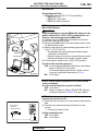
DIAGNOSTIC BY DIAGNOSTIC TEST MODE II
(INCREASED SENSITIVITY)
Required Special Tools:
• MB991958: Scan tool (M.U.T.-III Sub Assembly)
• MB991824: V.C.I.
• MB991827: USB Cable
• MB991910: Main Harness A
Data link connector
MB991910
MB991824
MB991827
AC608435 AB
CAUTION
To prevent damage to scan tool MB991958, always turn the
ignition switch to the "LOCK" (OFF) position before connecting or disconnecting scan tool MB991958.
NOTE: When mode II is selected with MB991958, the Malfunction Indicator Lamp (SERVICE ENGINE SOON or Check
Engine Lamp) will light when the engine control module (ECM)
first detects the trouble (Note that this is only for emission-related trouble). At the same time, the relevant diagnostic
trouble codes will be registered. In respect to the comprehensive component electrical faults (opens/shorts), the time for the
diagnostic trouble code to be registered after the fault occurrence is four seconds →one second. Therefore, the confirmation of the trouble symptom and the confirmation after
completing repairs can be reduced. To return to the normal
mode I after mode II has been selected once, the ignition
switch must be turned "OFF" once or mode I must be reselected with the scan tool MB991958. The diagnostic trouble
code, system readiness test status and freeze frame data, etc.,
will be erased when mode I is returned to, so record these
before returning to mode I.
1. Connect scan tool MB991958 to the data link connector.
2. Turn the ignition switch to the "ON" position.
3. Change the diagnostic test mode of the engine control
module to DIAGNOSTIC TEST MODE II (INCREASED
SENSITIVITY).
4. Road test the vehicle.
5. Read the diagnostic trouble code and repair the
malfunctioning part.
6. Turn the ignition switch to the "LOCK" (OFF) position.
7. Disconnect scan tool MB991958 from the data link
connector.
TSB Revision
13A-23
MULTIPORT FUEL INJECTION (MFI)
MULTIPORT FUEL INJECTION (MFI) DIAGNOSIS
ON-BOARD DIAGNOSTICS
The engine control module (ECM) monitors the
input/output signals (some signals all the time and
others under specified conditions) of the ECM. When
a malfunction continues for a specified time or longer
after the irregular signal is initially monitored, the
ECM judges that a malfunction has occurred. After
the ECM first detects a malfunction, a diagnostic
trouble code is recorded when the engine is restarted
and the same malfunction is re-detected. However,
for items marked with a "*", a diagnostic trouble code
is recorded on the first detection of the malfunction.
There are 134 diagnostic items. The diagnostic
results can be read out with a scan tool. Since memorization of the diagnostic trouble codes is backed up
directly by the battery, the diagnostic results are
memorized even if the ignition key is turned off. The
diagnostic trouble codes will, however, be erased
when the battery terminal or the ECM connector is
disconnected. In addition, the diagnostic trouble
code can also be erased by turning the ignition
switch to ON and sending the diagnostic trouble
code erase signal from scan tool MB991958 to the
ECM.
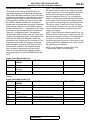
Freeze Frame Data for M.U.T.-III
ITEM NO. M.U.T.-III SCAN TOOL
DISPLAY
1
Odometer
2
Ignition cycle (Warm
up cycle)
4
Accumulated minute
NOTE: If the sensor connector is disconnected with
the ignition switch turned on, the diagnostic trouble
code is memorized. In this case, send the diagnostic
trouble code erase signal to the ECM in order to
erase the diagnostic memory. The 134 diagnostic
items are all indicated sequentially from the smallest
code number. The ECM records the engine operating condition when the diagnostic trouble code is set.
This data is called "Freeze-frame" data. This data
can be read by using the scan tool, and can then be
used in simulation tests for troubleshooting. Data
items are as follows:
NOTE: If the ECM detects multiple malfunctions, the
ECM stores the "Freeze-frame" data for only the first
item that was detected. However, if the ECM detects
a misfire or a fuel system malfunction, the ECM
stores the data by giving priority to the misfire or fuel
system malfunction, regardless of the order in which
the malfunction was detected.
NOTE: As for Diagnostic trouble code P1603,
"Freeze-frame" data is not memorized.
DATA ITEM
UNIT or STATE
Odometer
Ignition cycle (Warm up cycle)
km
Accumulated minute*
min
−
NOTE: *: The total time, in which the failure determination is carried out while the ignition switch is in the ON
position.
Freeze Frame Data for M.U.T.-III
ITEM NO. M.U.T.-III SCAN TOOL
DISPLAY
AA
Airflow sensor
AB
TP sensor (main)
BB
Barometric pressure
sensor
BC
Relative TP sensor
BD
TP sensor (sub)
BE
APP sensor (main)
BF
APP sensor (sub)
DATA ITEM
UNIT or STATE
Mass airflow sensor
Throttle position sensor (main)
Barometric pressure sensor
g/s
%
kPa or in.Hg
Relative throttle position sensor
Throttle position sensor (sub)
Accelerator pedal position sensor (main)
Accelerator pedal position sensor (sub)
%
%
%
%
TSB Revision
13A-24
MULTIPORT FUEL INJECTION (MFI)
MULTIPORT FUEL INJECTION (MFI) DIAGNOSIS
ITEM NO. M.U.T.-III SCAN TOOL DATA ITEM
DISPLAY
C0
Fuel system status
Fuel system status
(bank 1)
C1*
C2
C3
C4
C5*
C6
C7*
CC
CD
CE
CF
D0
D1
D6
D7
D8
D9
DA
DB
DC
UNIT or STATE
• Open loop
• Closed loop
• Open loop-drive
condition
• Open loop-DTC set
• Closed loop-O2 (rear)
failed
N/A
Fuel system status
(bank 2)
Calculated load value
ECT sensor
Fuel system status (bank 2)
Short term fuel trim
(bank 1)
Short term fuel trim
(bank 3)
Long term fuel trim
(bank 1)
Long term fuel trim
(bank 3)
MAP sensor
Crankshaft position
sensor
Vehicle speed
Spark advance
Intake air temperature
sensor
Time since engine
running
EVAP. emission purge
SOL. duty
Fuel level gauge
Power supply voltage
Absolute load value
Target equivalence
ratio
Intake air temperature
sensor
Throttle actuator
Short term fuel trim
° C or ° F
%
Short term fuel trim (bank 3)
****
Long term fuel trim
%
Long term fuel trim (bank 3)
****
Manifold absolute pressure sensor
Crankshaft position sensor
kPa or in.Hg
r/min
Vehicle speed
Spark advance
Intake air temperature sensor
km/h or mph
deg
Time since engine running
sec
Evaporative emission purge solenoid
duty
Fuel level gauge
Power supply voltage
Absolute load value
Target equivalence ratio
%
Intake air temperature sensor
°F
Throttle actuator control motor
%
Calculated load value
Engine coolant temperature sensor
%
° C or ° F
%
V
%
NOTE: *Data items are displayed on M.U.T.-III display, but the in-line 4 engine is not applicable and its data is
displayed as "N/A" or "****".
TSB Revision
MULTIPORT FUEL INJECTION (MFI)
MULTIPORT FUEL INJECTION (MFI) DIAGNOSIS
13A-25
Freeze Frame Data for General Scan Tool
COMMON EXAMPLE of PRAMETER
GENERAL SCAN
IDENTIFICATION
TOOL DISPLAY
(PID)
DESCRIPTION
UNIT or STATE
DTCFRZF
FUELSYS 1
LOAD_PCT
ECT
SHRTFT 1
LONGFT 1
MAP
RPM
VSS
SPARKADV
IAT
MAF
TP
RUNTM
EVAP_PCT
FLI
BARO
VPWR
LOAD_ABS
EQ_RAT
TP_R
AAT
02
03
04
05
06
07
0B
0C
0D
0E
0F
10
11
1F
2E
2F
33
42
43
44
45
46
TP_B
APP_D
APP_E
TAC_PCT
47
49
4A
4C
DTC that caused required freeze frame data storage Pxxxx, Uxxxx
See M.U.T.-III Item No. C0
See M.U.T.-III Item No. C2
See M.U.T.-III Item No. C3
See M.U.T.-III Item No. C4
See M.U.T.-III Item No. C6
See M.U.T.-III Item No. CC
See M.U.T.-III Item No. CD
See M.U.T.-III Item No. CE
See M.U.T.-III Item No. CF
See M.U.T.-III Item No. D0
See M.U.T.-III Item No. AA
See M.U.T.-III Item No. AB
See M.U.T.-III Item No. D1
See M.U.T.-III Item No. D6
See M.U.T.-III Item No. D7
See M.U.T.-III Item No. BB
See M.U.T.-III Item No. D8
See M.U.T.-III Item No. D9
See M.U.T.-III Item No. DA
See M.U.T.-III Item No. BC
Ambient air temperature
° C (° F)
See M.U.T.-III Item No. BD
See M.U.T.-III Item No. BE
See M.U.T.-III Item No. BF
Command Throttle Actuator Control
%
OBD- II DRIVE CYCLE
All kinds of diagnostic trouble codes (DTCs) can be monitored by carrying out a short drive according to the
following 23 drive cycle patterns. In other words, doing such a drive regenerates any kind of trouble which
involves illuminating the Malfunction Indicator Lamp (SERVICE ENGINE SOON or Check Engine Lamp) and
verifies the repair procedure has been eliminated [the trouble the Malfunction Indicator Lamp (SERVICE
ENGINE SOON or Check Engine Lamp) is no longer illuminated].
CAUTION
Two technicians should always be in the vehicle when carrying out a test.
NOTE: Check that the diagnosis trouble code (DTC) is not output before driving the OBD-II drive cycle. Erase
the DTC if it has been output.
NOTE: Drive cycle patterns are not established for Vehicle speed signal monitor (DTC P0500), Power steering pressure switch monitor (P0551), and Fuel level sensor monitor (DTC P0461, P2066). Please reference
the M.U.T. data list to judge whether these monitor items are normal.
TSB Revision
13A-26
MULTIPORT FUEL INJECTION (MFI)
MULTIPORT FUEL INJECTION (MFI) DIAGNOSIS
DRIVE CYCLE PATTERN LIST
MONITOR ITEM
Heated oxygen sensor (front) monitor <Readiness test
item>
Heated oxygen sensor heater monitor <Readiness test
item>
Catalytic converter monitor <Readiness test item>
Evaporative emission system leak monitor (small leak and
gross leak) <Readiness test item>
Evaporative purge system monitor
Fuel tank pressure sensor monitor
Evaporative emission system leak monitor (very small leak)
<Readiness test item>
Airflow sensor monitor
Manifold absolute pressure (MAP) sensor monitor
Intake air temperature sensor monitor
Engine coolant temperature sensor monitor
Thermostat monitor
Heated oxygen sensor (rear) monitor <Readiness test
item>
Air fuel ratio feedback monitor
Heated oxygen sensor (rear) monitor
Fuel tank temperature sensor monitor
Misfire monitor
Fuel tank pressure sensor monitor
Power steering pressure switch monitor
Throttle position sensor plausibility monitor
Mass airflow sensor plausibility monitor
Torque monitor
Wastegate system monitor
Idle speed control system monitor
Idle speed control system monitor
Ignition timing retard control (cold start strategy) monitor
Variable valve timing system (MIVEC) monitor
Fuel trim monitor
Heated oxygen sensor monitor
TSB Revision
DIAGNOSTIC TROUBLE
CODE (DTC)
P0133
PATTERN
P0031, P0032, P0037,
P0038
P0420
P0442, P0455
2
P0441
P0450
P0456
1
3
4
5
P0101
P0106, P0107
P0096, P0111
P0116, P0125
P0128
P0139
6
P0134
P0140
P0181
P0300, P0301, P0302,
P0303, P0304
P0451
P0554
P1233, P1234
P1235, P1238
P1241
P0234
P0506, P0507
P1506, P1507
P1320
P0011, P0014, P0016, P0017
P0171, P0172
P0131, P0137, P2195
11
12
13
14
7
8
9
10
15
16
17
18
19
20
21
22
MULTIPORT FUEL INJECTION (MFI)
MULTIPORT FUEL INJECTION (MFI) DIAGNOSIS
MONITOR ITEM
Intake air temperature sensor monitor
Airflow sensor monitor
Manifold absolute pressure (MAP) sensor monitor
Engine coolant temperature sensor monitor
Heated oxygen sensor monitor
Fuel tank temperature sensor monitor
Injector monitor
Turbocharger wastgate solenoid monitor
Knock sensor monitor
Crankshaft position sensor monitor
Evaporative emission purge solenoid monitor
Evaporative emission ventilation solenoid monitor
Fuel tank pressure sensor monitor
Fuel level sensor monitor
Engine oil control valve monitor
Engine RPM plausibility monitor
Barometric pressure sensor monitor
.
TSB Revision
13A-27
DIAGNOSTIC TROUBLE
PATTERN
CODE (DTC)
P0097, P0098, P0112, P0113 23
P0102, P0103
P0108
P0117, P0118
P0132, P0138, P2252,
P2253
P0182, P0183
P0201, P0202, P0203,
P0204
P0243, P0247
P0327, P0328
P0335
P0443
P0446
P0452, P0453
P0462, P0463
P1021, P1025
P1239
P2228, P2229
13A-28
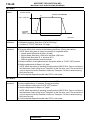
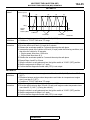
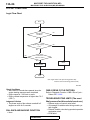
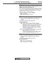
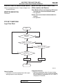
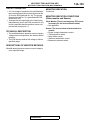
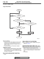
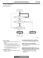
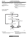
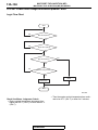
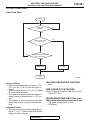
PATTERN 1
Drive cycle
pattern
MULTIPORT FUEL INJECTION (MFI)
MULTIPORT FUEL INJECTION (MFI) DIAGNOSIS
ENGINE SPEED
DURING THE MONITOR
(2)
1,500 - 3,500 r/min
(3)
IGNITION
SWITCH:
"LOCK" (OFF)
(1)
2 MINUTES
TIME
AK402430 AJ
Inspection
conditions
• Engine coolant temperature: More than 82° C (180° F)
• Barometric pressure: More than 76 kPa (22.5 inHg)
• Condition of TC-SST: Shift lever "D" range
Test
procedure
1. Start the engine with all the accessories switched OFF.
2. Drive the vehicle for 4 minutes at the following conditions. (During the monitor)
NOTE: When the system is normal, the monitor is completed earlier.
• Vehicle speed: More than 30 km/h (19 mph)
• Engine speed: More than 1,500 r/min, less than 3,500 r/min
• Engine load: More than 20 %, less than 60 %
• Without rapid accelerator pedal movement
3. Stop the vehicle in a safe place and turn the ignition switch to "LOCK" (OFF) position.
4. Start the engine and do Steps 1 to 3 again.
NOTE: When the vehicle is operating normally and the OBD-II Drive Cycle is carried out,
the Readiness Codes will be set as "Complete" on the first drive cycle. The second drive
cycle is required to set the Readiness Codes as "Complete" if a fault is detected during
the first drive cycle.
5. Confirm that the diagnostic trouble code (DTC) is not output.
.
PATTERN 2
Test
procedure
1. Start the engine with all the accessories switched OFF.
2. Let the engine idle for 10 seconds. (During the monitor)
3. Turn the ignition switch to the "LOCK" (OFF) position.
4. Start the engine and do Steps 1 to 3 again.
NOTE: When the vehicle is operating normally and the OBD-II Drive Cycle is carried out,
the Readiness Codes will be set as "Complete" on the first drive cycle. The second drive
cycle is required to set the Readiness Codes as "Complete" if a fault is detected during
the first drive cycle.
5. Confirm that the diagnostic trouble code (DTC) is not output.
.
TSB Revision
13A-29
MULTIPORT FUEL INJECTION (MFI)
MULTIPORT FUEL INJECTION (MFI) DIAGNOSIS
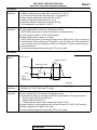
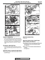
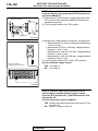
PATTERN 3
Drive cycle
pattern
Engine speed
During the monitor
3,500 r/min
(2)
During the monitor
(4)
(3)
(5)
(1)
Ignition
switch:
"LOCK" (OFF)
5 Minutes
Time
5 Seconds
3 Minutes
AK402432AD
Inspection
conditions
•
•
•
•
Test
procedure
1. Start the engine with all accessories switched OFF.
2. Drive the vehicle for 5 minutes at the following conditions. (During the monitor)
• Engine speed: Less than 3,500 r/min
• Airflow rate: More than 13 g/sec, less than 45 g/sec
• Accelerator pedal: Except full close
• Without rapid accelerator pedal movement
3. Release the accelerator pedal for 5 seconds.
4. Drive the vehicle for 3 minutes at the following conditions. (During the monitor)
• Engine speed: Less than 3,500 r/min
• Airflow rate: More than 13 g/sec, less than 45 g/sec
• Accelerator pedal: Except full close
• Without rapid accelerator pedal movement
NOTE: When the system is normal, the monitor is completed earlier.
5. Stop the vehicle in a safe place and turn the ignition switch to "LOCK" (OFF) position.
6. Start the engine and do Steps 1 to 5 again.
NOTE: When the vehicle is operating normally and the OBD-II Drive Cycle is carried out,
the Readiness Codes will be set as "Complete" on the first drive cycle. The second drive
cycle is required to set the Readiness Codes as "Complete" if a fault is detected during
the first drive cycle.
7. Confirm that the diagnostic trouble code (DTC) is not output.
Engine coolant temperature: More than 30° C (86° F)
Intake air temperature: More than −10° C (14° F)
Barometric pressure: More than 76 kPa (22.5 inHg)
Condition of TC-SST: Shift lever "D" range
.
TSB Revision
13A-30
MULTIPORT FUEL INJECTION (MFI)
MULTIPORT FUEL INJECTION (MFI) DIAGNOSIS
PATTERN 4
Drive cycle
pattern
Engine speed
During the monitor
(2)
1,600 - 4,000 r/min
(3)
Ignition
switch:
"LOCK" (OFF)
(1)
16 Minutes
Time
AK402430 AI
Inspection
conditions
•
•
•
•
•
•
•
•
Test
procedure
1. Start the engine with all the accessories switched OFF.
2. Drive the vehicle for 16 minutes at the following conditions. (During the monitor)
• Engine speed: More than 1,600 r/min, less than 4,000 r/min
• Vehicle speed: More than 30 km/h (18.7 mph)
• Engine load: More than 20 %, less than 50 %
• Without rapid accelerator pedal movement
NOTE: Keep running as long as possible with the power steering pressure switch in
the OFF position.
NOTE: When the system is normal, the monitor is completed earlier.
3. Stop the vehicle in a safe place and turn the ignition switch to "LOCK" (OFF) position.
4. Start the engine and do Steps 1 to 3 again.
NOTE: When the vehicle is operating normally and the OBD-II Drive Cycle is carried out,
the Readiness Codes will be set as "Complete" on the first drive cycle. The second drive
cycle is required to set the Readiness Codes as "Complete" if a fault is detected during
the first drive cycle.
5. Confirm that the diagnostic trouble code (DTC) is not output.
Engine coolant temperature at engine start: Less than 36° C (96° F)
Intake air temperature at engine start: Less than 36° C (96° F)
Fuel amount at engine start: More than 15 %, less than 40 %
Engine coolant temperature: More than 60° C (41° F)
Intake air temperature: More than 5° C (41° F)
Barometric pressure: More than 76 kPa (22.5 inHg)
Fuel temperature: Less than 36° C (96° F)
Condition of TC-SST: Shift lever "D" range
.
TSB Revision
13A-31
MULTIPORT FUEL INJECTION (MFI)
MULTIPORT FUEL INJECTION (MFI) DIAGNOSIS
PATTERN 5
Inspection
conditions
Test
procedure
•
•
•
•
•
•
•
Engine coolant temperature at engine start: Less than 36° C (96° F)
Intake air temperature at engine start: Less than 36° C (96° F)
Fuel amount at engine start: More than 40 %, less than 85 %
Engine coolant temperature: More than 20° C (68° F)
Intake air temperature: More than 5° C (41° F)
Barometric pressure: More than 76 kPa (22.5 inHg)
Fuel temperature: Less than 32° C (90° F)
1. Start the engine with all the accessories switched OFF.
2. Let the engine idle for 16 minutes. (During the monitor)
NOTE: When the system is normal, the monitor is completed earlier.
3. Turn the ignition switch to "LOCK" (OFF) position.
4. Start the engine and do Steps 1 to 3 again.
NOTE: When the vehicle is operating normally and the OBD-II Drive Cycle is carried out,
the Readiness Codes will be set as "Complete" on the first drive cycle. The second drive
cycle is required to set the Readiness Codes as "Complete" if a fault is detected during
the first drive cycle.
5. Confirm that the diagnostic trouble code (DTC) is not output.
.
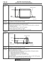
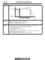
PATTERN 6
Drive cycle
pattern
Engine speed
During the monitor
(3)
During the monitor
(4)
2,000 r/min
(2)
Idling
(1)
Ignition
switch:
"LOCK" (OFF)
Time
30 Seconds
2 Seconds
AK402442 AC
Inspection
conditions
Test
procedure
• Engine coolant temperature at engine start: More than 0° C (32° F)
• Condition of TC-SST: Shift lever "D" range
1. Start the engine with all the accessories switched OFF.
2. Let the engine idle for 30 seconds. (During the monitor)
3. Accelerate the vehicle for 2 seconds at the following conditions. (During the monitor)
• Engine speed: More than 2,000 r/min
• Engine load: More than 20 %
• Throttle position sensor output voltage: More than 3.5 volts
4. Stop the vehicle in a safe place and turn the ignition switch to "LOCK" (OFF) position.
5. Start the engine and do Steps 1 to 4 again.
6. Confirm that the diagnostic trouble code (DTC) is not output.
.
TSB Revision
13A-32
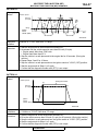
PATTERN 7
Drive cycle
pattern
MULTIPORT FUEL INJECTION (MFI)
MULTIPORT FUEL INJECTION (MFI) DIAGNOSIS
Vehicle speed
(2)
(2)
50 km/h
(31 mph)
(3)
(3)
Idling
(1)
Ignition
switch:
"LOCK" (OFF)
(5)
Time
1 Minute
1 Minute
30 Seconds
30 Seconds
AK402435 AC
Inspection
conditions
Test
procedure
• Engine coolant temperature: More than 76° C (169° F)
• Condition of TC-SST: Shift lever "D" range
1. Start the engine with all the accessories switched OFF.
2. Drive the vehicle at more than 50 km/h (31 mph) for 1 minute.
3. Stop the vehicle in a safe place and let the engine idle for 30 seconds.
4. Repeat Steps 2 and 3 again.
5. Stop the vehicle in a safe place and turn the ignition switch to "LOCK" (OFF) position.
6. Confirm that the diagnostic trouble code (DTC) is not output.
.
PATTERN 8
Drive cycle
pattern
Vehicle speed
During the monitor
(2)
50 km/h
(32 mph)
Ignition
switch:
"LOCK" (OFF)
(3)
(1)
6 Minutes
Time
AK402441AM
Inspection
conditions
•
•
•
•
Test
procedure
1. Start the engine with all the accessories switched OFF.
2. Drive the vehicle for 6 minutes at the following condition. (During the monitor)
• Vehicle speed: More than 50 km/h (32 mph)
• Except fuel cut
3. Stop the vehicle in a safe place and turn the ignition switch to "LOCK" (OFF) position.
4. Confirm that the diagnostic trouble code (DTC) is not output.
Engine coolant temperature at engine start: More than 7° C (47° F)
Intake air temperature: Less than 60° C (140° F)
Engine coolant temperature: More than 40° C (104° F)
Condition of TC-SST: Shift lever "D" range
.
TSB Revision
13A-33
MULTIPORT FUEL INJECTION (MFI)
MULTIPORT FUEL INJECTION (MFI) DIAGNOSIS
PATTERN 9
Drive cycle
pattern
Vehicle speed
During the monitor
(2)
50 km/h
(31 mph)
Ignition
switch:
"LOCK" (OFF)
(3)
(1)
44 minutes
Time
AK402441AN
Inspection
conditions
• Engine coolant temperature at engine start: More than 10° C (50° F), less than 60° C
(168° F)
• Intake air temperature at engine start: More than 10° C (14° F)
• Dropping of intake air temperature since engine start: Less than 5° C (9° F)
• Condition of TC-SST: Shift lever "D" range
Test
procedure
1. Start the engine with all the accessories switched OFF.
2. Drive the vehicle for 20 minutes at the following conditions. (During the monitor)
• Vehicle speed: More than 50 km/h (32 mph)
• Except fuel cut
NOTE: The system is normal if engine coolant temperature will rise more than 82° C
(180° F) within 44 minutes.
3. Stop the vehicle in a safe place and turn the ignition switch to "LOCK" (OFF) position.
4. Start the engine and do Steps 1 to 3 again.
5. Confirm that the diagnostic trouble code (DTC) is not output.
.
TSB Revision
13A-34
PATTERN 10
Drive cycle
pattern
MULTIPORT FUEL INJECTION (MFI)
MULTIPORT FUEL INJECTION (MFI) DIAGNOSIS
Vehicle speed
During the monitor
(2)
50 km/h
(32 mph)
Ignition
switch:
"LOCK" (OFF)
(3)
(1)
(4)
6 Minutes
Time
AK604701AB
Inspection
conditions
Test
procedure
• Engine coolant temperature: More than 76° C (169° F)
• Condition of TC-SST: Shift lever "D" range
1. Start the engine with all the accessories switched OFF.
2. Drive the vehicle at 50 km/h (31 mph) for 6 minutes.
3. Release the accelerator pedal for 10 seconds then stop the vehicle in a safe place.
(During the monitor)
4. Turn the ignition switch to "LOCK" (OFF) position.
5. Start the engine and do Steps 1 to 4 again.
6. Confirm that the diagnostic trouble code (DTC) is not output.
.
PATTERN 11
Drive cycle
pattern
Engine speed
During the monitor
(3)
1,800 r/min
(4)
(2)
Idling
Ignition
switch:
"LOCK" (OFF)
(1)
3 Minutes
30 Seconds
Time
AK402436 AC
Inspection
conditions
Test
procedure
• Engine coolant temperature: More than 82° C (180° F)
• Condition of TC-SST: Shift lever "D" range
1. Start the engine with all the accessories switched OFF.
2. Let the engine idle for 3 minutes.
3. Drive the vehicle for 30 seconds at the following conditions. (During the monitor)
• Engine speed: More than 1,800 r/min
• Engine load: More than 30 %, less than 80 %
• Throttle position sensor output: Less than 3.0 volts
• Except fuel cut
4. Stop the vehicle in a safe place and turn the ignition switch to "LOCK" (OFF) position.
5. Confirm that the diagnostic trouble code (DTC) is not output.
TSB Revision
13A-35
MULTIPORT FUEL INJECTION (MFI)
MULTIPORT FUEL INJECTION (MFI) DIAGNOSIS
PATTERN 12
.
Drive cycle
pattern
Vehicle speed
(2)
50 km/h
(31 mph)
(4)
(3)
(4)
(4)
(5)
(5)
(5)
Idling
Ignition
switch:
"LOCK" (OFF)
(1)
(7)
Time
5 Minutes
5 Seconds
5 Seconds
AK402437AC
Inspection
conditions
Test
procedure
• Engine coolant temperature: More than 76° C (169° F)
• Condition of TC-SST: Shift lever "D" range
1. Start the engine with all the accessories switched OFF.
2. Drive the vehicle at 50 km/h (31 mph) for 5 minutes.
3. Release the accelerator pedal for 5 seconds then stop the safe place.
4. Increase the speed of the vehicle to 50 km/h (31 mph) under the following conditions, and
then drive the vehicle for 30 seconds.
• Engine speed: More than 1,500 r/min
• Engine load: More than 40 %
5. Release the accelerator pedal for 5 seconds then stop the safe place.
6. Repeat Steps 4 and 5 for 2 times.
7. Stop the vehicle in a safe place and turn the ignition switch to "LOCK" (OFF) position.
8. Start the engine and do Steps 1 to 7 again.
9. Confirm that the diagnostic trouble code (DTC) is not output.
.
PATTERN 13
Inspection
conditions
Test
procedure
• Engine coolant temperature at engine start: More than −10° C (14° F), less than 33° C
(91° F)
• Difference between engine coolant temperature and intake air temperature at engine
start: Less than 5° C (9° F)
• Condition of TC-SST: Shift lever "D" range
1. Start the engine with all the accessories switched OFF.
2. Drive the vehicle at more than 30 km/h (19 mph) until engine coolant temperature rises
more than 60° C (140° F). (During the monitor)
3. Stop the vehicle in a safe place and turn the ignition switch to "LOCK" (OFF) position.
4. Start the engine and do Steps 1 to 3 again.
5. Confirm that the diagnostic trouble code (DTC) is not output.
.
TSB Revision
13A-36
MULTIPORT FUEL INJECTION (MFI)
MULTIPORT FUEL INJECTION (MFI) DIAGNOSIS
PATTERN 14
Drive cycle
pattern
Engine speed
During the monitor
(2)
500 - 3,000 r/min
(3)
Ignition
switch:
"LOCK" (OFF)
(1)
3 Minutes
Time
AK402440 AE
Inspection
conditions
•
•
•
•
Engine coolant temperature: More than −10° C (14° F)
Intake air temperature: More than −10° C (14° F)
Barometric pressure: More than 76 kPa (22.5 inHg)
Condition of TC-SST: Shift lever "D" range
Test
procedure
1. Start the engine with all the accessories switched OFF.
2. Drive the vehicle for 3 minutes at the following conditions. (During the monitor)
• Engine speed: More than 500 r/min, less than 3,000 r/min
• Engine load: More than 25 %
• Without rapid accelerator pedal change
• Except fuel cut
3. Stop the vehicle in a safe place and turn the ignition switch to "LOCK" (OFF) position.
4. Start the engine and do Steps 1 to 3 again.
5. Confirm that the diagnostic trouble code (DTC) is not output.
.
TSB Revision
13A-37
MULTIPORT FUEL INJECTION (MFI)
MULTIPORT FUEL INJECTION (MFI) DIAGNOSIS
PATTERN 15
Drive cycle
pattern
Vehicle speed
(2)
50 km/h
(31 mph)
(3)
(2)
2nd
monitor
1st
monitor
Idling
Ignition
switch:
"LOCK" (OFF)
(2)
(2)
(2)
9th
monitor
(3)
(3)
(3)
10th
monitor
(5)
(1)
Time
20 seconds
20 seconds
AK402438 AC
Inspection
condition
Condition of TC-SST: Shift lever "D" range
Test
procedure
1. Start the engine with all the accessories switched OFF.
2. Accelerate until the vehicle speed is more than 50 km/h (31 mph).
• Engine speed: More than 2,500 r/min
• Engine load: More than 55 %
3. Stop the vehicle in a safe place and let the engine idle for 20 seconds. (During the
monitor)
4. Repeat Steps 2 and 3 for 10 times.
5. Stop the vehicle in a safe place and turn the ignition switch to "LOCK" (OFF) position.
6. Start the engine and do Steps 1 to 5 again.
7. Confirm that the diagnostic trouble code (DTC) is not output.
.
PATTERN 16
Drive cycle
pattern
Vehicle speed
During the monitor
(2)
50 km/h
(31 mph)
Ignition
switch:
"LOCK" (OFF)
(3)
(1)
30 seconds
Time
AK402441AP
Inspection
conditions
Test
procedure
• Engine coolant temperature: More than 65° C (149° F)
• Condition of TC-SST: Shift lever "D" range
1. Start the engine with all the accessories switched OFF.
2. Drive the vehicle at more than 50 km/h (31 mph) for 30 seconds. (During the monitor)
3. Stop the vehicle in a safe place and turn the ignition switch to "LOCK" (OFF) position.
4. Start the engine and do Steps 1 to 3 again.
5. Confirm that the diagnostic trouble code (DTC) is not output.
TSB Revision
13A-38
MULTIPORT FUEL INJECTION (MFI)
MULTIPORT FUEL INJECTION (MFI) DIAGNOSIS
.
PATTERN 17
Inspection
conditions
Test
procedure
Condition of TC-SST: Shift lever "D" range
1. Start the engine with all the accessories switched OFF.
2. Drive the vehicle with the accelerator pedal fully depressed for 5 seconds. (During the
monitor)
3. Stop at safe place and turn the ignition switch to "LOCK" (OFF) position.
4. Start the engine and do Steps 1 to 3 again.
5. Confirm that the diagnostic trouble code (DTC) is not output.
.
PATTERN 18
Inspection
conditions
Test
procedure
• Engine coolant temperature: More than 82° C (180° F)
• Intake air temperature: More than −10° C (14° F)
• Barometric pressure: More than 76 kPa (22.5 inHg)
1. Start the engine with all the accessories switched OFF.
2. Accelerate until the vehicle speed is more than 1.5 km/h (1 mph).
3. Stop the vehicle in a safe place and let the engine idle for 1 minute. (During the monitor)
4. Turn the ignition switch to "LOCK" (OFF) position.
5. Start the engine and do Steps 1 to 4 again.
6. Confirm that the diagnostic trouble code (DTC) is not output.
.
PATTERN 19
Inspection
conditions
Test
procedure
• Engine coolant temperature: More than 7° C (45° F), less than 36° C (97° F)
• Intake air temperature: More than −10° C (14° F)
• Barometric pressure: More than 76 kPa (22.5 inHg)
1. Start the engine with all the accessories switched OFF.
2. Let the engine idle for 1 minute. (During the monitor)
3. Turn the ignition switch to "LOCK" (OFF) position.
4. Start the engine and do Steps 1 to 3 again.
5. Confirm that the diagnostic trouble code (DTC) is not output.
.
PATTERN 20
Inspection
conditions
Test
procedure
• Engine coolant temperature: More than 77° C (171° F), less than 87° C (189° F)
• Barometric pressure: More than 76 kPa (22.5 inHg)
1. Start the engine with all the accessories switched OFF.
2. Drive the engine at 1,200 −1,500 r/min for 30 seconds. (During the monitor)
3. Turn the ignition switch to "LOCK" (OFF) position.
4. Start the engine and do Steps 1 to 3 again.
5. Confirm that the diagnostic trouble code (DTC) is not output.
.
TSB Revision
MULTIPORT FUEL INJECTION (MFI)
MULTIPORT FUEL INJECTION (MFI) DIAGNOSIS
PATTERN 21
Inspection
condition
Test
procedure
13A-39
Engine coolant temperature: More than 82° C (180° F)
1. Start the engine with all the accessories switched OFF.
2. Let the engine idle for 15 minutes. (During the monitor)
3. Turn the ignition switch to "LOCK" (OFF) position.
4. Start the engine and do Steps 1 to 3 again.
5. Confirm that the diagnostic trouble code (DTC) is not output.
.
PATTERN 22
Inspection
conditions
Test
procedure
• Intake air temperature: More than −10° C (14° F)
• Engine coolant temperature sensor: More than 7° C (45° F)
1. Start the engine with all the accessories switched OFF.
2. Let the engine idle for 4 minutes. (During the monitor)
3. Turn the ignition switch to "LOCK" (OFF) position.
4. Start the engine and do Steps 1 to 3 again.
5. Confirm that the diagnostic trouble code (DTC) is not output.
.
PATTERN 23
Inspection
conditions
Test
procedure
• Fuel temperature sensor: Less than 36° C (96° F) <Fuel tank pressure sensor monitor>
• Fuel amount at engine start: Less than 85 % <Fuel tank pressure sensor monitor>
1. Start the engine with all the accessories switched OFF.
2. Let the engine idle at the engine speed less than 1,000 r/min for 15 seconds. (During the
monitor)
3. Turn the ignition switch to "LOCK" (OFF) position.
4. Confirm that the diagnostic trouble code (DTC) is not output.
SYSTEM READINESS TEST STATUS
.
PURPOSE
The Readiness function (also referred to as I/M
Readiness or I/M Flags) indicates if a full diagnostic
check has been "Completed" (is "Ready") for each
non-continuous monitor. Enhanced I/M State Emission Programs will use the Readiness status (Codes)
to see if the vehicle is ready for OBD-II testing.
"Incomplete" (Not Ready) codes will be one of the
triggers for I/M failure.
.
OVERVIEW
The ECM monitors the following main diagnosis
items and records whether the evaluation was completed or is incomplete. The Readiness Codes are
established for the I/M programs, thereby confirming
that the vehicles have not been tampered with by
erasing the diagnostic trouble code(s) (DTCs) before
TSB Revision
I/M testing. The Readiness Codes and DTCs can be
reset by disconnecting the battery or by erasing the
codes with a scan tool MB991958 (M.U.T.-III sub
assembly). For this reason, all the Readiness Codes
must be displayed "Complete" before I/M testing.
When the monitors run and complete, the scan tool
MB991958 (M.U.T.-III sub assembly) will display the
Readiness Codes as "Complete" (General Scan
Tools display as "Ready"). When the vehicle is operating normally and the OBD-II Drive Cycle is carried
out, the Readiness Codes will be set as "Complete"
on the first drive cycle. For DTCs requiring two drive
cycles to detect a fault, the second drive cycle is
required to set the Readiness Codes as "Complete"
if a fault is detected during the first drive cycle. If the
fault is still there after the second drive cycle, a DTC
will be set.
• Catalyst: P0420
• Evaporative system: P0442, P0455, P0456
• Heated oxygen sensor: P0133, P0139
• Heated oxygen sensor heater: P0031, P0032,
P0037, P0038
13A-40
MULTIPORT FUEL INJECTION (MFI)
MULTIPORT FUEL INJECTION (MFI) DIAGNOSIS
After all the Readiness Codes are displayed as
"Complete", the technician is assured that any DTCs
related to the monitor will be displayed if the system
has a problem. That is why some State's I/M programs require the Readiness Code as "Complete"
before they check for DTCs.
NOTE: After a repair is made for a DTC, the technician should drive the OBD-II Drive Cycle checking
that the scan tool MB991958 (M.U.T.-III Sub Assembly) displays all the Readiness Codes as "Complete".
FAIL-SAFE FUNCTION REFERENCE TABLE
M1131153000857
The control is carried out, which keeps the safety driving by the preset controllogic when the diagnosis code
is output. The diagnosis code having the fail-safe function is as follows.
DTC
P0096
P0097
P0098
P0111
P0112
P0113
P0116
P0117
P0118
P0122
P0123
P0125
P0222
P0223
P0234
DIAGNOSTIC ITEM
Intake air temperature circuit
range/performance problem (sensor 2)
Intake air temperature circuit low input
(sensor 2)
Intake air temperature circuit high input
(sensor 2)
Intake air temperature circuit
range/performance problem (sensor 1)
Intake air temperature circuit low input
(sensor 1)
Intake air temperature circuit high input
(sensor 1)
Engine coolant temperature circuit
range/performance problem
Engine coolant temperature circuit low input
FAIL-SAFE AND BACKUP FUNCTION
Control as if the intake air temperature in the
intake manifold is 25° C.
Control as if the intake air temperature in the
intake manifold is 25° C.
Control as if the intake air temperature in the
intake manifold is 25° C.
Control as if the intake air temperature is
25° C.
Control as if the intake air temperature is
25° C.
Control as if the intake air temperature is
25° C.
Control as if the engine coolant temperature
is 80° C.
Control as if the engine coolant temperature
is 80° C.
Engine coolant temperature circuit high input Control as if the engine coolant temperature
is 80° C.
Throttle position sensor (main) circuit low
• Throttle opening degree is restricted.
• Throttle opening degree position is in
input
default position if throttle position sensor
(sub) fails.
Throttle position sensor (main) circuit high
• Throttle opening degree is restricted.
input
• Throttle opening degree position is in
default position if throttle position sensor
(sub) fails.
Insufficient coolant temperature for closed
Control as if the engine coolant temperature
loop fuel control
is 80° C.
Throttle position sensor (sub) circuit low input • Throttle opening degree is restricted.
• Throttle opening degree position is in
default position if throttle position sensor
(main) fails.
Throttle position sensor (sub) circuit high
• Throttle opening degree is restricted.
• Throttle opening degree position is in
input
default position if throttle position sensor
(main) fails.
Turbocharger wastegate system malfunction Fuel is cut in abnormal engine overboost
condition.
TSB Revision
MULTIPORT FUEL INJECTION (MFI)
MULTIPORT FUEL INJECTION (MFI) DIAGNOSIS
DTC
P0300
DIAGNOSTIC ITEM
Random/multiple cylinder misfire detected
P0301
Cylinder 1 misfire detected
P0302
Cylinder 2 misfire detected
P0303
Cylinder 3 misfire detected
P0304
Cylinder 4 misfire detected
P0327
Knock sensor circuit low
P0328
Knock sensor circuit high
P0340
Intake camshaft position sensor circuit
P0365
Exhaust camshaft position sensor circuit
P0513
P0606
Immobilizer malfunction
Engine control module main processor
malfunction
Generator FR terminal circuit malfunction
P0622
P0638
P0642
P0657
Throttle actuator control motor circuit
range/performance
Throttle position sensor power supply
P1021
Throttle actuator control motor relay circuit
malfunction
Intake engine oil control valve circuit
P1025
Exhaust engine oil control valve circuit
P1231
Active stability control plausibility
P1232
P1233
Fail safe system
Throttle position sensor (main) plausibility
P1234
Throttle position sensor (sub) plausibility
TSB Revision
13A-41
FAIL-SAFE AND BACKUP FUNCTION
The supply of fuel to the misfiring cylinder
can possibly be cut.
The supply of fuel to the misfiring cylinder
can possibly be cut.
The supply of fuel to the misfiring cylinder
can possibly be cut.
The supply of fuel to the misfiring cylinder
can possibly be cut.
The supply of fuel to the misfiring cylinder
can possibly be cut.
Fix the ignition timing with an allowance
against knock.
Fix the ignition timing with an allowance
against knock.
• Engine runs in learned pattern until engine
stops.
• Does not control variable valve timing
(V.V.T.).
Does not control variable valve timing
(V.V.T.).
Engine start is prohibited.
Throttle opening degree position is in default
position.
Prohibits generator output suppression
control against current consumers.
(Operates as a normal generator.)
Throttle opening degree position is in default
position.
Throttle opening degree position is in default
position.
Throttle opening degree position is in default
position.
V.V.T.phase angle (intake) becomes most
retarded angle.
V.V.T.phase angle (exhaust) becomes most
advanced angle.
Torque requested by active stability control
(ASC) is ignored.
Microcomputer is reset.
• Throttle opening degree is restricted.
• Throttle opening degree position is in
default position if throttle position sensor
(sub) fails.
• Throttle opening degree is restricted.
• Throttle opening degree position is in
default position if throttle position sensor
(main) fails.
13A-42
DTC
P1235
P1236
P1237
P1238
P1239
P1240
P1241
P1242
P1243
P1244
P1245
P1247
P1590
P1603
P2100
P2101
P2122
P2123
P2127
P2128
P2135
MULTIPORT FUEL INJECTION (MFI)
MULTIPORT FUEL INJECTION (MFI) DIAGNOSIS
DIAGNOSTIC ITEM
Mass airflow sensor plausibility
FAIL-SAFE AND BACKUP FUNCTION
Fuel control is carried out using throttle
opening degree and engine speed in
accordance with preset map.
A/D converter
Throttle opening degree position is in default
position.
Accelerator pedal position sensor plausibility Throttle opening degree position is in default
position.
Mass airflow sensor plausibility (torque
Throttle opening degree position is in default
monitor)
position.
Engine RPM plausibility
Throttle opening degree position is in default
position.
Ignition angle
Ignition retard is not carried out.
Torque monitor
Throttle opening degree position is in default
position.
Fail safe control monitor
Throttle opening degree position is in default
position.
Inquiry/response error
Microcomputer is reset.
RAM test for all area
Microcomputer is reset.
Cycle RAM test (engine)
Microcomputer is reset.
TC-SST plausibility <TC-SST>
Torque requested by TC-SST-ECU is
ignored.
TCM to ECM communication error in torque Engine output is restricted.
reduction request <TC-SST>
Battery backup circuit malfunction
All diagnosis codes are stored once failure
judgment is completed.
Throttle actuator control motor circuit (open) Throttle opening degree position is in default
position.
Throttle actuator control motor magneto
Throttle opening degree position is in default
malfunction
position.
Accelerator pedal position sensor (main)
• Throttle opening degree is restricted.
circuit low input
• Throttle opening degree position is in
default position if accelerator pedal
position sensor (sub) fails.
Accelerator pedal position sensor (main)
• Throttle opening degree is restricted.
• Throttle opening degree position is in
circuit high input
default position if accelerator pedal
position sensor (sub) fails.
Accelerator pedal position sensor (sub)
• Throttle opening degree is restricted.
circuit low input
• Throttle opening degree position is in
default position if accelerator pedal
position sensor (main) fails.
Accelerator pedal position sensor (sub)
• Throttle opening degree is restricted.
circuit high input
• Throttle opening degree position is in
default position if accelerator pedal
position sensor (main) fails.
Throttle position sensor (main and sub)
Throttle opening degree position is in default
range/performance problem
position.
TSB Revision
MULTIPORT FUEL INJECTION (MFI)
MULTIPORT FUEL INJECTION (MFI) DIAGNOSIS
DTC
P2138
P2228
P2229
P2253
P2263
U0167
13A-43
DIAGNOSTIC ITEM
FAIL-SAFE AND BACKUP FUNCTION
Accelerator pedal position sensor (main and • Throttle opening degree is restricted.
sub) range/performance problem
• Throttle opening degree position is in
default position if accelerator pedal
position sensor (sub) fails.
Barometric pressure circuit low input
Control as if the barometric pressure is 101
kPa.
Barometric pressure circuit high input
Control as if the barometric pressure is 101
kPa.
Heated oxygen sensor offset circuit high
Does not control air-fuel ratio closed loop.
voltage
Intake charge system malfunction
Fuel is cut in engine overboost condition.
Immobilizer communication error
Engine start is prohibited.
TSB Revision
13A-44
MULTIPORT FUEL INJECTION (MFI)
MULTIPORT FUEL INJECTION (MFI) DIAGNOSIS
DIAGNOSTIC TROUBLE CODE CHART
M1131151003399
CAUTION
During diagnosis, a DTC code associated with other system may be set when the ignition switch is
turned on with connector(s) disconnected. On completion, confirm all systems for DTC(s). If DTC(s)
are set, erase them all.
DTC
DIAGNOSTIC ITEM
REFERENCE
PAGE
P0011
Intake variable valve timing system target error
P0012
P0014
Camshaft position - timing over-retarded
Exhaust variable valve timing system target error
P.13A-51
P.13A-54
P0016
P0017
P0031
Crankshaft/camshaft (intake) position sensor phase problem
Crankshaft/camshaft (exhaust) position sensor phase problem
Heated oxygen sensor (front) heater circuit low
P0032
P0037
P0038
Heated oxygen sensor (front) heater circuit high
Heated oxygen sensor (rear) heater circuit low
Heated oxygen sensor (rear) heater circuit high
P0069
P0096*
Abnormal correlation between manifold absolute pressure sensor and barometric
pressure sensor
Intake air temperature circuit range/performance problem (sensor 2)
P0097*
Intake air temperature circuit low input (sensor 2)
P.13A-98
P0098
P0101*
Intake air temperature circuit high input (sensor 2)
P.13A-101
Mass airflow circuit range/performance problem
P0102*
P0103*
P0106
Mass airflow circuit low input
Mass airflow circuit high input
Manifold absolute pressure circuit range/performance problem
P.13A-107
P.13A-113
P.13A-120
P0107
P0108
P0111*
Manifold absolute pressure circuit low input
Manifold absolute pressure circuit high input
Intake air temperature circuit range/performance problem (sensor 1)
P0112*
P0113*
Intake air temperature circuit low input (sensor 1)
Intake air temperature circuit high input (sensor 1)
P0116*
P0117*
P0118*
Engine coolant temperature circuit range/performance problem
Engine coolant temperature circuit low input
Engine coolant temperature circuit high input
P0122*
P0123*
P0125*
Throttle position sensor (main) circuit low input
Throttle position sensor (main) circuit high input
Insufficient coolant temperature for closed loop fuel control
*
P.13A-55
P.13A-58
P.13A-62
P.13A-66
P.13A-73
P.13A-77
P.13A-84
P.13A-88
P.13A-92
P.13A-125
P.13A-134
P.13A-142
P.13A-147
P.13A-153
P.13A-157
P.13A-163
P.13A-169
P.13A-174
P.13A-181
P.13A-185
P0128
P0131
P.13A-192
Coolant thermostat (coolant temperature below thermostat regulating temperature) P.13A-200
Heated oxygen sensor (front) circuit low voltage
P.13A-203
P0132
P0133
P0134*
Heated oxygen sensor (front) circuit high voltage
Heated oxygen sensor (front) circuit slow response
Heated oxygen sensor (front) circuit no activity detected
P0137
P0138
Heated oxygen sensor (rear) circuit low voltage
Heated oxygen sensor (rear) circuit high voltage
TSB Revision
P.13A-211
P.13A-215
P.13A-220
P.13A-226
P.13A-234
MULTIPORT FUEL INJECTION (MFI)
MULTIPORT FUEL INJECTION (MFI) DIAGNOSIS
13A-45
DTC
DIAGNOSTIC ITEM
REFERENCE
PAGE
P0139
P0140
P0171
Heated oxygen sensor (rear) circuit slow response
Heated oxygen sensor (rear) circuit no activity detected
System too lean
P.13A-238
P.13A-242
P0172
P0181
P0182
System too rich
Fuel tank temperature sensor circuit range/performance
Fuel tank temperature sensor circuit low input
P0183
P0201
Fuel tank temperature sensor circuit high input
Injector circuit-cylinder 1
P0202
P0203
P0204
Injector circuit-cylinder 2
Injector circuit-cylinder 3
Injector circuit-cylinder 4
P0222*
P0223*
P0234
Throttle position sensor (sub) circuit low input
Throttle position sensor (sub) circuit high input
Turbocharger wastegate system malfunction
P0243
P0247
Turbocharger wastegate solenoid 1 circuit
Turbocharger wastegate solenoid 2 circuit
P0300
P0301
P0302
Random/multiple cylinder misfire detected
Cylinder 1 misfire detected
Cylinder 2 misfire detected
P0303
P0304
P0327
Cylinder 3 misfire detected
Cylinder 4 misfire detected
Knock sensor circuit low
P0328
P0335*
Knock sensor circuit high
Crankshaft position sensor circuit
P0340*
P0365*
P0420
Intake camshaft position sensor circuit
Exhaust camshaft position sensor circuit
Warm up catalyst efficiency below threshold
P0441
P0442
P0443
Evaporative emission control system incorrect purge flow
Evaporative emission control system leak detected (small leak)
Evaporative emission purge solenoid circuit
P0446
P0450
Evaporative emission ventilation solenoid circuit
Fuel tank differential pressure sensor malfunction
P0451
P0452
P0453
Fuel tank differential pressure circuit range/performance problem
Fuel tank differential pressure circuit low input
Fuel tank differential pressure circuit high input
P0455
P0456
P0461
Evaporative emission control system leak detected (gross leak)
Evaporative emission control system leak detected (very small leak)
Fuel level sensor (main) circuit range/performance
P0462
P0463
Fuel level sensor circuit low input
Fuel level sensor circuit high input
P0500*
Vehicle speed signal malfunction
TSB Revision
P.13A-246
P.13A-252
P.13A-258
P.13A-265
P.13A-270
P.13A-277
P.13A-287
P.13A-297
P.13A-307
P.13A-317
P.13A-323
P.13A-328
P.13A-330
P.13A-337
P.13A-343
P.13A-348
P.13A-351
P.13A-354
P.13A-357
P.13A-361
P.13A-364
P.13A-367
P.13A-377
P.13A-385
P.13A-394
P.13A-396
P.13A-400
P.13A-412
P.13A-419
P.13A-426
P.13A-435
P.13A-444
P.13A-455
P.13A-512
P.13A-523
P.13A-534
P.13A-537
P.13A-540
P.13A-542
13A-46
MULTIPORT FUEL INJECTION (MFI)
MULTIPORT FUEL INJECTION (MFI) DIAGNOSIS
DTC
DIAGNOSTIC ITEM
REFERENCE
PAGE
P0506
P0507
P0513
Idle control system RPM lower than expected
Idle control system RPM higher than expected
Immobilizer malfunction
P.13A-545
P.13A-548
P0551
P0554
P0603*
Power steering pressure switch circuit range/performance
Power steering pressure switch circuit intermittent
EEPROM malfunction
P0606*
P0622
Engine control module main processor malfunction
Generator FR terminal circuit malfunction
P0630*
P0638*
P0642*
Vehicle Identification Number (VIN) malfunction
Throttle actuator control motor circuit range/performance
Throttle position sensor power supply
P0657*
P0830
P1021
Throttle actuator control motor relay circuit malfunction
Clutch pedal position switch circuit range/performance
Intake engine oil control valve circuit
P1025
P1231
Exhaust engine oil control valve circuit
Active stability control plausibility
P1232
P1233*
P1234*
Fail safe system
Throttle position sensor (main) plausibility
Throttle position sensor (sub) plausibility
P1235*
P1236*
P1237*
Mass airflow sensor plausibility
A/D converter
Accelerator pedal position sensor plausibility
P1238*
P1239*
Mass airflow sensor plausibility (torque monitor)
Engine RPM plausibility
P1240
P1241*
P1242
Ignition angle
Torque monitor
Fail safe control monitor
P1243
P1244
P1245
Inquiry/response error
RAM test for all area
Cycle RAM test (engine)
P1247
P1320
TC-SST plausibility <TC-SST>
Ignition timing retard insufficient
P1506
P1507
P1590*
Idle control system RPM lower than expected at low temperature
Idle control system RPM higher than expected at low temperature
TCM to ECM communication error in torque reduction request <TC-SST>
P1603*
P1676*
P2066
Battery backup circuit malfunction
Variant coding
Fuel level sensor (sub) circuit range/performance
P2100*
P2101*
Throttle actuator control motor circuit (open)
Throttle actuator control motor magneto malfunction
P2122*
Accelerator pedal position sensor (main) circuit low input
TSB Revision
P.13A-551
P.13A-553
P.13A-560
P.13A-564
P.13A-566
P.13A-568
P.13A-573
P.13A-575
P.13A-579
P.13A-581
P.13A-589
P.13A-594
P.13A-601
P.13A-607
P.13A-609
P.13A-610
P.13A-614
P.13A-617
P.13A-620
P.13A-621
P.13A-624
P.13A-628
P.13A-630
P.13A-631
P.13A-635
P.13A-637
P.13A-638
P.13A-639
P.13A-640
P.13A-641
P.13A-644
P.13A-647
P.13A-650
P.13A-653
P.13A-657
P.13A-659
P.13A-663
P.13A-668
P.13A-672
MULTIPORT FUEL INJECTION (MFI)
MULTIPORT FUEL INJECTION (MFI) DIAGNOSIS
13A-47
DTC
DIAGNOSTIC ITEM
REFERENCE
PAGE
P2123*
P2127*
P2128*
Accelerator pedal position sensor (main) circuit high input
Accelerator pedal position sensor (sub) circuit low input
Accelerator pedal position sensor (sub) circuit high input
P.13A-677
P.13A-682
P2135*
P2138*
P2195
Throttle position sensor (main and sub) range/performance problem
Accelerator pedal position sensor (main and sub) range/performance problem
Heated Oxygen Sensor (front) Inactive
P2228*
P2229*
Barometric pressure circuit low input
Barometric pressure circuit high input
P2252
P2253
P2263
Heated oxygen sensor offset circuit low voltage
Heated oxygen sensor offset circuit high voltage
Intake charge system malfunction
U0001
U0101*
U0121*
Bus off
TC-SST-ECU time-out <TC-SST>
ASC-ECU time-out
U0141*
U0167
ETACS-ECU time-out
Immobilizer communication error
U1180*
Combination meter time-out
P.13A-687
P.13A-691
P.13A-697
P.13A-704
P.13A-707
P.13A-709
P.13A-711
P.13A-713
P.13A-715
P.13A-718
P.13A-719
P.13A-723
P.13A-727
P.13A-731
P.13A-733
NOTE: Do not replace the engine control module (ECM) until a through terminal check reveals there are no
short/open circuits.
NOTE: Check that the ECM ground circuit is normal before checking for the cause of the problem.
NOTE: After the ECM detects a malfunction, a diagnostic trouble code is recorded the next time the engine is
started and the same malfunction is re-detected. However, for items marked with a "*", the diagnostic trouble
code is recorded on the first detection of the malfunction.
NOTE: Sensor 1 of the heated oxygen sensor indicates the sensor mounted at a position closest to the
engine, and sensor 2 of the heated oxygen sensor indicates the sensor mounted at the position second closest to the engine.
TSB Revision
13A-48
MULTIPORT FUEL INJECTION (MFI)
MULTIPORT FUEL INJECTION (MFI) DIAGNOSIS
SYMPTOM CHART
M1131151502711
CAUTION
During diagnosis, a DTC associated with other systems may be set when the ignition switch is turned
on with connector(s) disconnected. On completion, confirm all systems for DTC(s). If DTC(s) are set,
erase them all.
CAUTION
Disconnecting the battery cables or removing the combination meter will erase the learned value of
the fuel gauge. To recover the learned value, input a vehicle speed (by actually driving the vehicle or
inputting a simulated vehicle speed), and stop the vehicle. This will complete the learning process.
NOTE: Check that the ECM ground circuit is normal before checking for the cause of the problem.
NOTE: When the racing (3,000 to 5,000 r/min or more) continues on the vehicle stopped with no load during
the specified time or more, the increase in the engine speed might be limited. This comes from the engine
protection and control functions and is not a malfunction.
.
TROUBLE SYMPTOMS
INSPECTION
PROCEDURE
REFERENCE PAGE
Communication
with scan tool is
impossible
Communication with ECM only is not possible
1
P.13A-737
Malfunction
Indicator Lamp
(SERVICE
ENGINE SOON or
Check Engine
Lamp) and related
parts
The Malfunction Indicator Lamp (SERVICE
2
ENGINE SOON or Check Engine Lamp) does not
illuminate right after the ignition switch is turned to
the "ON" position
P.13A-741
The Malfunction Indicator Lamp (SERVICE
ENGINE SOON or Check Engine Lamp) remains
illuminated and never goes out
3
P.13A-742
Starting
Cranks, won't start
4
P.13A-744
Starts up and dies
5
P.13A-751
Hard starting
6
P.13A-755
Unstable idle (rough idle, hunting)
7
P.13A-760
Idle speed is high (improper idle speed)
8
P.13A-764
Idle speed is low (improper idle speed)
9
P.13A-765
When the engine is cold, it stalls at idle (die out)
10
P.13A-766
When the engine is hot, it stalls at idle (die out)
11
P.13A-769
The engine stalls when accelerating (pass out)
12
P.13A-772
The engine stalls when decelerating
13
P.13A-774
Hesitation, sag, Stumble, Poor acceleration or
Surge
14
P.13A-776
Acceleration shock
15
P.13A-779
Knocking
16
P.13A-781
17
P.13A-782
Idling stability
(improper idling)
Idling stability
(engine stalls)
Driving
Too high CO and HC concentration when idling
TSB Revision
MULTIPORT FUEL INJECTION (MFI)
MULTIPORT FUEL INJECTION (MFI) DIAGNOSIS
13A-49
TROUBLE SYMPTOMS
INSPECTION
PROCEDURE
REFERENCE PAGE
IM240 test failure
Transient, mass emission tailpipe test failure
18
P.13A-785
Purge flow test of the evaporative emission
canister failure
19
P.13A-789
Pressure test of the evaporative system failure
20
P.13A-789
Generator output voltage is low (approximately 12.3 volts)
21
P.13A-791
Power supply system and ignition switch-IG system
22
P.13A-794
Fuel pump system
23
P.13A-805
Ignition switch-ST system and starter relay system <M/T>
24
P.13A-818
Ignition switch-ST system and starter relay system <TC-SST>
25
P.13A-830
Ignition circuit system
26
P.13A-842
A/C system
27
P.13A-847
Engine oil pressure switch system
28
P.13A-849
.
PROBLEM SYMPTOMS TABLE (FOR YOUR INFORMATION)
ITEMS
At starting
Won't start
Starts up and
dies
Hard starting
Idling stability Hunting
Rough idle
SYMPTOM
The starter cranks the engine, but there is no combustion within the
cylinders, and the engine won't start.
The engine starts, but then engine soon stalls.
Engine starts after cranking a while.
Engine speed doesn't remain constant; changes at idle.
Usually, a judgement can be based upon the movement of the
tachometer pointer, and the vibration transmitted to the steering wheel,
shift lever, body, etc.
The engine doesn't idle at the correct speed.
Incorrect idle
speed
Engine stall (die The engine stalls when the foot is taken from the accelerator pedal,
out)
regardless of whether the vehicle is moving or not.
Engine stall (pass The engine stalls when the accelerator pedal is depressed.
out)
TSB Revision
13A-50
ITEMS
At driving
MULTIPORT FUEL INJECTION (MFI)
MULTIPORT FUEL INJECTION (MFI) DIAGNOSIS
Hesitation Sag
SYMPTOM
"Hesitation" is the delay in
response of the vehicle speed
(engine speed). This occurs
when the accelerator is
depressed in order to accelerate
from the speed at which the
vehicle is now traveling, or a
temporary drop in vehicle speed
(engine speed) during such
acceleration.
Serious hesitation is called
"sag".
Vehicle
speed
Hesitation
Normal
Initial
accelerator
pedal
depression
Sag
Time
AKX01361 AC
Poor acceleration Poor acceleration is inability to obtain an acceleration corresponding to
the degree of throttle opening, even though acceleration is smooth. Also
the inability to reach maximum speed.
Stumble
Engine speed increase is
Vehicle
delayed when the accelerator
speed
pedal is initially depressed for
acceleration.
Initial Normal
accelerator
pedal
depression
Idling
Stumble
Time
Shock
Surge
Knocking
At stopped
Run on
("Dieseling")
AKX01362 AD
The feeling of a comparatively large impact or vibration when the engine
is accelerated or decelerated.
This is slight acceleration and deceleration feel usually felt during
steady, light throttle cruise. Most notable under light loads.
A sharp sound during driving, which sounds like a hammer striking the
cylinder walls. It makes poor driveability.
The condition in which the engine continues to run after the ignition
switch is turned to the "LOCK" (OFF) position. Also called "dieseling".
TSB Revision
MULTIPORT FUEL INJECTION (MFI)
MULTIPORT FUEL INJECTION (MFI) DIAGNOSIS
13A-51
DIAGNOSTIC TROUBLE CODE PROCEDURES
DTC P0011: Intake Variable Valve Timing System Target Error
.
TECHNICAL DESCRIPTION
• The ECM checks the variable valve timing system for malfunction.
.
DESCRIPTIONS OF MONITOR METHODS
The phase angle of the intake camshaft is higher
than the specified value.
.
MONITOR EXECUTION
Continuous
.
MONITOR EXECUTION CONDITIONS
(Other monitor and Sensor)
Other Monitor (There is no temporary DTC stored
in memory for the item monitored below)
• Not applicable
Sensor (The sensor below is determined to be
normal)
• Camshaft position sensor
• Crankshaft position sensor
• Engine coolant temperature sensor
• Throttle position sensor
• Engine oil control valve
.
TSB Revision
13A-52
MULTIPORT FUEL INJECTION (MFI)
MULTIPORT FUEL INJECTION (MFI) DIAGNOSIS
DTC SET CONDITIONS
Logic Flow Chart
Start
No
Monitoring
conditions
Yes
No
|Cam angle-target|
> 5˚CA
Yes
No
Continuous
failure for 5secs
Yes
Good
Malfunction
End
Cam angle: Intake valve open timing (intake side)
Exhaust valve close timing (exhaust side)
AK704222
Check Conditions
• More than 20 seconds have passed since the
engine starting sequence was completed.
• Engine speed is 1,188 r/min or more.
• Engine coolant temperature is higher than 76° C
(169° F).
Judgment Criterion
• The phase angle of the intake camshaft is 5
degrees or more for 5 seconds.
.
FAIL-SAFE AND BACKUP FUNCTION
• None
TSB Revision
.
OBD-II DRIVE CYCLE PATTERN
Refer to Diagnostic Function −OBD-II Drive Cycle −
Pattern 20 P.13A-9.
.
TROUBLESHOOTING HINTS (The most
likely causes for this code to be set are:)
• Intake engine oil control valve failed.
• Oil passage of variable valve timing control system clogged.
• Intake variable valve timing sprocket operation
mechanism stuck.
• ECM failed.
MULTIPORT FUEL INJECTION (MFI)
MULTIPORT FUEL INJECTION (MFI) DIAGNOSIS
13A-53
DIAGNOSIS
Required Special Tools
• MB991958: Scan tool (M.U.T.-III Sub Assembly)
• MB991824: V.C.I.
• MB991827: USB Cable
• MB991910: Main Harness A
STEP 1. Using scan tool MB991958, read the diagnostic
trouble code (DTC).
CAUTION
To prevent damage to scan tool MB991958, always turn the
ignition switch to the "LOCK" (OFF) position before connecting or disconnecting scan tool MB991958.
(1) Connect scan tool MB991958 to the data link connector.
(2) Turn the ignition switch to the "ON" position.
(3) Set scan tool MB991958, read the DTC.
(4) Turn the ignition switch to the "LOCK" (OFF) position.
Data link connector
Q: Is the diagnostic trouble code other than P0011 set?
YES : Refer to, Diagnostic Trouble Code Chart P.13A-44.
NO : Go to Step 2.
MB991910
MB991824
MB991827
AC608435 AB
STEP 2. Check intake engine oil control valve itself.
• Check intake engine oil control valve itself (Refer to Engine
Oil Control Valve Check P.13A-912).
Q: Is the check result normal?
YES : Go to Step 3.
NO : Replace intake engine oil control valve. Then go to
Step 6.
STEP 3. Check oil passage of intake variable valve timing
control system for being clogged.
Q: Is the check result normal?
YES : Go to Step 4.
NO : Repair it. Then go to Step 6.
STEP 4. Check intake variable valve timing sprocket
operation mechanism for being stuck.
Q: Is the check result normal?
YES : Go to Step 5.
NO : Repair it. Then go to Step 6.
TSB Revision
13A-54
MULTIPORT FUEL INJECTION (MFI)
MULTIPORT FUEL INJECTION (MFI) DIAGNOSIS
STEP 5. Check the trouble symptoms.
(1) Carry out test drive with the drive cycle pattern. Refer to
Diagnostic Function −OBD-II Drive Cycle −Pattern 20
P.13A-9.
(2) Check the diagnostic trouble code (DTC).
Q: Is DTC P0011 set?
YES : Replace the ECM. When the ECM is replaced,
register the ID code. Refer to GROUP 42B, ID Code
Registration Necessity Judgment Table <Vehicles
with KOS> P.42B-12 or GROUP 42C, ID Codes
Registration Judgment Table <Vehicles with WCM>
P.42C-9. Then go to Step 6.
NO : It can be assumed that this malfunction is intermittent.
Refer to GROUP 00, How to Use
Troubleshooting/Inspection Service Points −How to
Cope with Intermittent Malfunctions P.00-15.
STEP 6. Test the OBD-II drive cycle.
(1) Carry out a test drive with the drive cycle pattern. Refer to
Diagnostic Function −OBD-II Drive Cycle −Pattern 20
P.13A-9.
(2) Check the diagnostic trouble code (DTC).
Q: Is DTC P0011 set?
YES : Retry the troubleshooting.
NO : The inspection is complete.
DTC P0012: Camshaft Position −Timing Over-Retarded
.
TECHNICAL DESCRIPTION
• If the vehicle equipped with 4B11-T/C engine
continues the rough driving like competitive running (the running that constantly repeats the
cycle of the full opened position of the accelerator
pedal and the full closed position of the accelerator pedal.), the amount of carbon mixed into the
engine oil tends to increase. This can possibly
cause the timing chain to gradually elongate. To
prevent this, the function or logic monitoring the
amount of elongation of the timing chain is integrated into the ECM. The details are shown in
timing chain maintenance (Refer to GROUP 00,
Precautions Before Service −Timing Chain Maintenance P.00-33).
.
DTC SET CONDITIONS
Check Condition
• Ignition switch is "ON" position.
Judgment Criterion
• The learning value for the current phase angle of
V.V.T. at the intake (retard angle) side and the
exhaust (advanced angle) side is different from
the initial phase angle of V.V.T. by more than the
specified value.
.
FAIL-SAFE AND BACKUP FUNCTION
• None
.
TROUBLESHOOTING HINTS (The most
likely causes for this code to be set are: )
• Timing chain elongated.
TSB Revision
MULTIPORT FUEL INJECTION (MFI)
MULTIPORT FUEL INJECTION (MFI) DIAGNOSIS
13A-55
DIAGNOSIS
STEP 1. Timing Chain Elongation Visual Check
Refer to GROUP 11A, On-vehicle Service −Timing Chain Elongation Visual Check P.11A-17.
Q: Are there any abnormalities?
YES : Initialize the learning value for the elongation of the
timing chain. Refer to GROUP 00, Precautions Before
Service −Timing Chain Maintenance P.00-33.
NO : Replace the timing chain and the oil pump chain.
Then initialize the learning value for the elongation of
the timing chain. Refer to GROUP 00, Precautions
Before Service −Timing Chain Maintenance P.00-33.
DTC P0014: Exhaust Variable Valve Timing System Target Error
.
TECHNICAL DESCRIPTION
• The ECM checks the variable valve timing system for malfunction.
.
DESCRIPTIONS OF MONITOR METHODS
The phase angle of the exhaust camshaft is higher
than the specified value.
.
MONITOR EXECUTION
Continuous
.
MONITOR EXECUTION CONDITIONS
(Other monitor and Sensor)
Other Monitor (There is no temporary DTC stored
in memory for the item monitored below)
• Not applicable
Sensor (The sensor below is determined to be
normal)
• Camshaft position sensor
• Crankshaft position sensor
• Engine coolant temperature sensor
• Throttle position sensor
• Engine oil control valve
.
TSB Revision
13A-56
MULTIPORT FUEL INJECTION (MFI)
MULTIPORT FUEL INJECTION (MFI) DIAGNOSIS
DTC SET CONDITIONS
Logic Flow Chart
Start
No
Monitoring
conditions
Yes
No
|Cam angle-target|
> 5˚CA
Yes
No
Continuous
failure for 5secs
Yes
Good
Malfunction
End
Cam angle: Intake valve open timing (intake side)
Exhaust valve close timing (exhaust side)
AK704222
Check Conditions
• More than 20 seconds have passed since the
engine starting sequence was completed.
• Engine speed is 1,188 r/min or more.
• Engine coolant temperature is higher than 76° C
(169° F).
Judgment Criterion
• The phase angle of the exhaust camshaft is 5
degrees or more for 5 seconds.
.
FAIL-SAFE AND BACKUP FUNCTION
• None
TSB Revision
.
OBD-II DRIVE CYCLE PATTERN
Refer to Diagnostic Function −OBD-II Drive Cycle −
Pattern 20 P.13A-9.
.
TROUBLESHOOTING HINTS (The most
likely causes for this code to be set are:)
• Exhaust engine oil control valve failed.
• Oil passage of variable valve timing control system clogged.
• Exhaust variable valve timing sprocket operation
mechanism stuck.
• ECM failed.
MULTIPORT FUEL INJECTION (MFI)
MULTIPORT FUEL INJECTION (MFI) DIAGNOSIS
13A-57
DIAGNOSIS
Required Special Tools
• MB991958: Scan tool (M.U.T.-III Sub Assembly)
• MB991824: V.C.I.
• MB991827: USB Cable
• MB991910: Main Harness A
STEP 1. Using scan tool MB991958, read the diagnostic
trouble code (DTC).
CAUTION
To prevent damage to scan tool MB991958, always turn the
ignition switch to the "LOCK" (OFF) position before connecting or disconnecting scan tool MB991958.
(1) Connect scan tool MB991958 to the data link connector.
(2) Turn the ignition switch to the "ON" position.
(3) Set scan tool MB991958, read the DTC.
(4) Turn the ignition switch to the "LOCK" (OFF) position.
Data link connector
Q: Is the diagnostic trouble code other than P0014 set?
YES : Refer to, Diagnostic Trouble Code Chart P.13A-44.
NO : Go to Step 2.
MB991910
MB991824
MB991827
AC608435 AB
STEP 2. Check exhaust engine oil control valve itself.
• Check exhaust engine oil control valve itself (Refer to
Engine Oil Control Valve Check P.13A-912).
Q: Is the check result normal?
YES : Go to Step 3.
NO : Replace exhaust engine oil control valve. Then go to
Step 6.
STEP 3. Check oil passage of exhaust variable valve timing
control system for being clogged.
Q: Is the check result normal?
YES : Go to Step 4.
NO : Repair it. Then go to Step 6.
STEP 4. Check exhaust variable valve timing sprocket
operation mechanism for being stuck.
Q: Is the check result normal?
YES : Go to Step 5.
NO : Repair it. Then go to Step 6.
TSB Revision
13A-58
MULTIPORT FUEL INJECTION (MFI)
MULTIPORT FUEL INJECTION (MFI) DIAGNOSIS
STEP 5. Check the trouble symptoms.
(1) Carry out test drive with the drive cycle pattern. Refer to
Diagnostic Function −OBD-II Drive Cycle −Pattern 20
P.13A-9.
(2) Check the diagnostic trouble code (DTC).
Q: Is DTC P0014 set?
YES : Replace the ECM. When the ECM is replaced,
register the ID code. Refer to GROUP 42B, ID Code
Registration Necessity Judgment Table <Vehicles
with KOS> P.42B-12 or GROUP 42C, ID Codes
Registration Judgment Table <Vehicles with WCM>
P.42C-9. Then go to Step 6.
NO : It can be assumed that this malfunction is intermittent.
Refer to GROUP 00, How to Use
Troubleshooting/Inspection Service Points −How to
Cope with Intermittent Malfunctions P.00-15.
STEP 6. Test the OBD-II drive cycle.
(1) Carry out a test drive with the drive cycle pattern. Refer to
Diagnostic Function −OBD-II Drive Cycle −Pattern 20
P.13A-9.
(2) Check the diagnostic trouble code (DTC).
Q: Is DTC P0014 set?
YES : Retry the troubleshooting.
NO : The inspection is complete.
DTC P0016: Crankshaft/camshaft (intake) Position Sensor Phase Problem
.
TECHNICAL DESCRIPTION
• The ECM checks the variable valve timing system for malfunction.
.
DESCRIPTIONS OF MONITOR METHODS
The open timing of the intake valve is faster or slower
than the specified value.
.
MONITOR EXECUTION
Continuous
.
MONITOR EXECUTION CONDITIONS
(Other monitor and Sensor)
Other Monitor (There is no temporary DTC stored
in memory for the item monitored below)
• Not applicable
Sensor (The sensor below is determined to be
normal)
• Camshaft position sensor
• Crankshaft position sensor
• Engine coolant temperature sensor
• Throttle position sensor
• Engine oil control valve
.
TSB Revision
13A-59
MULTIPORT FUEL INJECTION (MFI)
MULTIPORT FUEL INJECTION (MFI) DIAGNOSIS
DTC SET CONDITIONS
Logic Flow Chart
Start
No
Monitoring
conditions
Yes
No
Engine oil control valve
solenoid OFF
Yes
No
Cam angle
< θ MIN
Yes
No
Yes
Continuous
failure for 10secs
Cam angle
> θ MAX
No
Yes
Malfunction
Good
End
Cam angle: Intake valve open timing (intake side)
Exhaust valve close timing (exhaust side)
θ MAX
: Maximum threshold value
θ MIN
: Minimum threshold value
AK604370
Check Conditions
• Engine speed is between 594 r/min and 1,500
r/min.
• Engine coolant temperature is between 20° C
(68° F) and 88° C (190° F).
• Intake engine oil control valve is "OFF".
• 1 second has elapsed after the above mentions
have been met.
Judgment Criterion
• The open timing of the intake valve is faster than
−25 degrees (ATDC) for 10 seconds.
or
• The open timing of the intake valve is slower than
5 degrees (ATDC) for 10 seconds.
.
TSB Revision
FAIL-SAFE AND BACKUP FUNCTION
• None
.
OBD-II DRIVE CYCLE PATTERN
Refer to Diagnostic Function −OBD-II Drive Cycle −
Pattern 20 P.13A-9.
.
TROUBLESHOOTING HINTS (The most
likely causes for this code to be set are:)
• Timing chain in out of place.
• Loose timing chain.
• Intake variable valve timing sprocket tooth coming off.
• ECM failed.
13A-60
MULTIPORT FUEL INJECTION (MFI)
MULTIPORT FUEL INJECTION (MFI) DIAGNOSIS
DIAGNOSIS
Required Special Tools
• MB991709: Test Harness
• MB992110: Power Plant ECU Check Harness
Oscilloscope
Crankshaft position
sensor connector
1 2 3
STEP 1. Using the oscilloscope, measure output wave
pattern at crankshaft position sensor and intake camshaft
position sensor.
(1) Disconnect the crankshaft position sensor connector B-13
and connect the test harness special tool (MB991709)
between the separated connectors.
(2) Connect the oscilloscope probe to the crankshaft position
sensor side connector terminal No. 3.
(3) Disconnect the intake camshaft position sensor connector
B-07, and connect test harness special tool (MB991709)
between the separated connectors.
MB991709
AK704086AB
Oscilloscope
Intake camshaft position
sensor connector
1 2 3
(4) Connect the oscilloscope probe to the intake camshaft
position sensor side connector terminal No. 3.
NOTE: When measuring with the ECM side connector, disconnect all ECM connectors. Connect the check harness
special tool (MB992110) between the separated connectors. Then connect the oscilloscope probe to the check harness connector terminal No. 8 (crankshaft position sensor)
and terminal No. 14 (intake camshaft position sensor).
(5) Start the engine and run at idle.
MB991709
AK604465 AD
(6) Check the waveform.
• The waveform should show a pattern similar to the illustration.
(7) Turn the ignition switch to the "LOCK" (OFF) position.
Normal waveform
(Volt)
2 engine revolutions
Q: Is the waveform normal?
YES : Go to Step 2.
NO : Go to Step 3.
Crankshaft position sensor
output wave pattern
5
0
Intake camshaft position sensor
output ware pattern
5
0
AK704223 AB
TSB Revision
MULTIPORT FUEL INJECTION (MFI)
MULTIPORT FUEL INJECTION (MFI) DIAGNOSIS
13A-61
STEP 2. Check the trouble symptoms.
(1) Carry out a test drive with the drive cycle pattern. Refer to
Diagnostic Function −OBD-II Drive Cycle −Pattern 20
P.13A-9.
(2) Check the diagnostic trouble code (DTC).
Q: Is DTC P0016 set?
YES : Replace the ECM. When the ECM is replaced,
register the ID code. Refer to GROUP 42B, ID Code
Registration Necessity Judgment Table <Vehicles
with KOS> P.42B-12 or GROUP 42C, ID Codes
Registration Judgment Table <Vehicles with WCM>
P.42C-9. Then go to Step 4.
NO : It can be assumed that this malfunction is intermittent.
Refer to GROUP 00, How to Use Troubleshooting/
Inspection Service Points −How to Cope with
Intermittent Malfunctions P.00-15.
STEP 3. Check timing mark on the timing chain.
Q: Is timing chain in out of place?
YES : Repair it. Then go to Step 4.
NO : Check the following items, and repair or replace the
defective items.
a. Check the timing chain loose.
b. Check the intake variable valve timing
sprocket tooth coming off.
Then go to Step 4.
STEP 4. Test the OBD-II drive cycle.
(1) Carry out a test drive with the drive cycle pattern. Refer to
Diagnostic Function −OBD-II Drive Cycle −Pattern 20
P.13A-9.
(2) Check the diagnostic trouble code (DTC).
Q: Is DTC P0016 set?
YES : Retry the troubleshooting.
NO : The inspection is complete.
TSB Revision
13A-62
MULTIPORT FUEL INJECTION (MFI)
MULTIPORT FUEL INJECTION (MFI) DIAGNOSIS
DTC P0017: Crankshaft/camshaft (exhaust) Position Sensor Phase Problem
.
TECHNICAL DESCRIPTION
• The ECM checks the variable valve timing system for malfunction.
.
DESCRIPTIONS OF MONITOR METHODS
The close timing of the exhaust valve is faster or
slower than the specified value.
.
MONITOR EXECUTION
Continuous
.
MONITOR EXECUTION CONDITIONS
(Other monitor and Sensor)
Other Monitor (There is no temporary DTC stored
in memory for the item monitored below)
• Not applicable
Sensor (The sensor below is determined to be
normal)
• Camshaft position sensor
• Crankshaft position sensor
• Engine coolant temperature sensor
• Throttle position sensor
• Engine oil control valve
.
TSB Revision
13A-63
MULTIPORT FUEL INJECTION (MFI)
MULTIPORT FUEL INJECTION (MFI) DIAGNOSIS
DTC SET CONDITIONS
Logic Flow Chart
Start
No
Monitoring
conditions
Yes
No
Engine oil control valve
solenoid OFF
Yes
No
Cam angle
< θ MIN
Yes
No
Yes
Continuous
failure for 10secs
Cam angle
> θ MAX
No
Yes
Malfunction
Good
End
Cam angle: Intake valve open timing (intake side)
Exhaust valve close timing (exhaust side)
θ MAX
: Maximum threshold value
θ MIN
: Minimum threshold value
AK604370
Check Conditions
• Engine speed is between 594 r/min and 1,500
r/min.
• Engine coolant temperature is between 20° C
(68° F) and 88° C (190° F).
• Exhaust engine oil control valve is "OFF".
• 1 second has elapsed after the above mentions
have been met.
Judgment Criterion
• The close timing of the exhaust valve is faster
than −15 degrees (ATDC) for 10 seconds.
or
• The close timing of the exhaust valve is slower
than 15 degrees (ATDC) for 10 seconds.
.
TSB Revision
FAIL-SAFE AND BACKUP FUNCTION
• None
.
OBD-II DRIVE CYCLE PATTERN
Refer to Diagnostic Function −OBD-II Drive Cycle −
Pattern 20 P.13A-9.
.
TROUBLESHOOTING HINTS (The most
likely causes for this code to be set are:)
• Timing chain in out of place.
• Loose timing chain.
• Exhaust variable valve timing sprocket tooth
coming off.
• ECM failed.
13A-64
MULTIPORT FUEL INJECTION (MFI)
MULTIPORT FUEL INJECTION (MFI) DIAGNOSIS
DIAGNOSIS
Required Special Tools
• MB991709: Test Harness
• MB992110: Power Plant ECU Check Harness
Oscilloscope
Crankshaft position
sensor connector
1 2 3
STEP 1. Using the oscilloscope, measure output wave
pattern at crankshaft position sensor and exhaust
camshaft position sensor.
(1) Disconnect the crankshaft position sensor connector B-13
and connect the test harness special tool (MB991709)
between the separated connectors.
(2) Connect the oscilloscope probe to the crankshaft position
sensor side connector terminal No. 3.
(3) Disconnect the exhaust camshaft position sensor connector
B-05, and connect test harness special tool (MB991709)
between the separated connectors.
MB991709
AK704086AB
Oscilloscope
Exhaust camshaft position
sensor connector
1 2 3
(4) Connect the oscilloscope probe to the exhaust camshaft
position sensor side connector terminal No. 3.
NOTE: When measuring with the ECM side connector, disconnect all ECM connectors. Connect the check harness
special tool (MB992110) between the separated connectors. Then connect the oscilloscope probe to the check harness connector terminal No. 8 (crankshaft position sensor)
and terminal No. 7 (exhaust camshaft position sensor).
(5) Start the engine and run at idle.
MB991709
AK604465 AE
(6) Check the waveform.
• The waveform should show a pattern similar to the illustration.
(7) Turn the ignition switch to the "LOCK" (OFF) position.
Normal waveform
(Volt)
2 engine revolutions
Q: Is the waveform normal?
YES : Go to Step 2.
NO : Go to Step 3.
Crankshaft position sensor
output wave pattern
5
0
Exhaust camshaft position sensor
output ware pattern
5
0
AK704224 AB
TSB Revision
MULTIPORT FUEL INJECTION (MFI)
MULTIPORT FUEL INJECTION (MFI) DIAGNOSIS
13A-65
STEP 2. Check the trouble symptoms.
(1) Carry out a test drive with the drive cycle pattern. Refer to
Diagnostic Function −OBD-II Drive Cycle −Pattern 20
P.13A-9.
(2) Check the diagnostic trouble code (DTC).
Q: Is DTC P0017 set?
YES : Replace the ECM. When the ECM is replaced,
register the ID code. Refer to GROUP 42B, ID Code
Registration Necessity Judgment Table <Vehicles
with KOS> P.42B-12 or GROUP 42C, ID Codes
Registration Judgment Table <Vehicles with WCM>
P.42C-9. Then go to Step 4.
NO : It can be assumed that this malfunction is intermittent.
Refer to GROUP 00, How to Use Troubleshooting/
Inspection Service Points −How to Cope with
Intermittent Malfunctions P.00-15.
STEP 3. Check timing mark on the timing chain.
Q: Is timing chain in out of place?
YES : Repair it. Then go to Step 4.
NO : Check the following items, and repair or replace the
defective items.
a. Check the timing chain loose.
b. Check the exhaust variable valve timing
sprocket tooth coming off.
Then go to Step 4.
STEP 4. Test the OBD-II drive cycle.
(1) Carry out a test drive with the drive cycle pattern. Refer to
Diagnostic Function −OBD-II Drive Cycle −Pattern 20
P.13A-9.
(2) Check the diagnostic trouble code (DTC).
Q: Is DTC P0017 set?
YES : Retry the troubleshooting.
NO : The inspection is complete.
TSB Revision
13A-66
MULTIPORT FUEL INJECTION (MFI)
MULTIPORT FUEL INJECTION (MFI) DIAGNOSIS
DTC P0031: Heated Oxygen Sensor (front) Heater Circuit Low
HEATED OXYGEN SENSOR (FRONT) HEATER CIRCUIT
WHITE
WHITE
FUSIBLE LINK 36
RELAY BOX
(ENGINE COMPARTMENT)
3
4
HEATED OXYGEN SENSOR
(FRONT)
A-34X
2
OFF
3
4
MFI
RELAY
C-34
ON
1
1 2
3 4
2
22
20A
2
BLUE
1
TO ECM
WHITE
B-09
1
2
4
TO ECM
3
TO ECM
A-13
8
BLUE-BLACK
1
1 2 3 4
5 6 7 8 9
10 11 12 13 14 15 16 17 18 19 20 21 22
34
3 4 5 6 7 8 9 10 11 12 13 14 15 16
17 18 19 20 21 22 23 24 25 26 27 28 29 30 31 32
33 34 35 36 37 38 39 40 41 42 43 44 45 46 47 48
ENGINE
CONTROL
MODULE
49 50 51 52 53 54 55 56 57 58 59 60 61 62 63 64
AK704225AB
TSB Revision
13A-67
MULTIPORT FUEL INJECTION (MFI)
MULTIPORT FUEL INJECTION (MFI) DIAGNOSIS
Connector: B-09
Connector: A-13
ECM
A-13
B-09 (GR)
AK704227 AB
AK704229AB
Connector: C-34
Connector: A-34X
MFI relay
Heated oxygen
sensor (front)
A-34X
AK704226 AB
C-34 (B)
SRS-ECU
AK704228 AB
DESCRIPTIONS OF MONITOR METHODS
.
CIRCUIT OPERATION
• Power is supplied from the MFI relay (terminal
No. 2) to the heated oxygen sensor (front) heater.
• The ECM (terminal No. 34) controls continuity to
the heated oxygen sensor (front) heater by turning the power transistor in the ECM "ON" and
"OFF".
Heated oxygen sensor heater (front) current or voltage is out of specified range.
.
MONITOR EXECUTION
Continuous
.
.
TECHNICAL DESCRIPTION
• The ECM checks whether the heater current is
within a specified range when the heater is energized.
• The ECM checks whether the heater voltage is
within a specified range when the heater is not
energized.
.
MONITOR EXECUTION CONDITIONS
(Other monitor and Sensor)
Other Monitor (There is no temporary DTC stored
in memory for the item monitored below)
• Not applicable
Sensor (The sensor below is determined to be
normal)
• Not applicable
.
TSB Revision
13A-68
MULTIPORT FUEL INJECTION (MFI)
MULTIPORT FUEL INJECTION (MFI) DIAGNOSIS
DTC SET CONDITIONS
Logic Flow Chart
Start
No
Monitoring
conditions
Yes
No
Heater ON
Yes
Voltage < 2.0V
No
Yes
Current < 0.17A
or
Current > 10.5A
No
Yes
No
Continuous
failure for 2secs
Yes
Good
Malfunction
End
AK604306
• While the heated oxygen sensor (front) heater is
off.
• Battery positive voltage is between 11 and 16.5
volts.
.
Check Conditions
• More than 2 seconds have passed since the
engine starting sequence was completed.
• While the heated oxygen sensor (front) heater is
on.
• Battery positive voltage is between 11 and 16.5
volts.
Judgement Criterion
• The heated oxygen sensor (front) heater current
has continued to be lower than 0.17 ampere for 2
seconds.
Check Conditions
• More than 2 seconds have passed since the
engine starting sequence was completed.
Judgement Criterion
• The heated oxygen sensor (front) heater voltage
has continued to be lower than 2.0 volts for 2 seconds.
.
FAIL-SAFE AND BACKUP FUNCTION
• None
.
OBD-II DRIVE CYCLE PATTERN
Refer to Diagnostic Function −OBD-II Drive Cycle −
Pattern 2 P.13A-9.
.
TSB Revision
MULTIPORT FUEL INJECTION (MFI)
MULTIPORT FUEL INJECTION (MFI) DIAGNOSIS
TROUBLESHOOTING HINTS (The most
likely causes for this code to be set are:)
13A-69
• Heated oxygen sensor (front) heater failed.
• ECM failed.
• Open or shorted heated oxygen sensor (front)
heater circuit, harness damage or connector
damage.
DIAGNOSIS
Required Special Tools:
• MB991658: Test Harness
• MB992110: Power Plant ECU Check Harness
STEP 1. Check harness connector C-34 at the heated
oxygen sensor (front) for damage.
Q: Is the harness connector in good condition?
YES : Go to Step 2.
NO : Repair or replace it. Refer to GROUP 00E, Harness
Connector Inspection P.00E-2. Then go to Step 12.
Heated oxygen
sensor component
side connector
MB991658
STEP 2. Check the heated oxygen sensor (front).
(1) Disconnect heated oxygen sensor (front) connector C-34
and connect test harness special tool, MB991658, to the
connector on the heated oxygen sensor (front) side.
(2) Measure the resistance between heated oxygen sensor
connector terminal No. 1 and terminal No. 2.
Standard value: 4.5 −8.0 Ω [at 20° C (68° F)]
Q: Is the measured resistance between 4.5 and 8.0 Ω [at
20° C (68° F)]?
YES : Go to Step 3.
NO : Replace the heated oxygen sensor (front). Then go to
Step 12.
AK604492AB
STEP 3. Measure the power supply voltage at heated
oxygen sensor (front) harness side connector C-34.
(1) Disconnect the connector C-34 and measure at the harness
side.
(2) Turn the ignition switch to the "ON" position.
(3) Measure the voltage between terminal No. 1 and ground.
• Voltage should be battery positive voltage.
(4) Turn the ignition switch to the "LOCK" (OFF) position.
C-34 harness
connector:
component side
Q: Is battery positive voltage (approximately 12 volts)
present?
YES : Go to Step 5.
NO : Go to Step 4.
2 1
4 3
AK604172 AH
TSB Revision
13A-70
MULTIPORT FUEL INJECTION (MFI)
MULTIPORT FUEL INJECTION (MFI) DIAGNOSIS
STEP 4. Check harness connector A-34X at the MFI relay
for damage.
Q: Is the harness connector in good condition?
YES : Repair harness wire between MFI relay connector
A-34X (terminal No. 2) and heated oxygen sensor
(front) connector C-34 (terminal No. 1) because of
open circuit or short circuit to ground. Then go to Step
12.
NO : Repair or replace it. Refer to GROUP 00E, Harness
Connector Inspection P.00E-2. Then go to Step 12.
STEP 5. Measure the power supply voltage at ECM
connector B-09 by using power plant ECU check harness
special tool MB992110.
(1) Disconnect all ECM connectors. Connect the power plant
ECU check harness special tool MB992110 between the
separated connectors.
(2) Turn the ignition switch to the "ON" position.
Body side harness
ECM
MB992110
AK604040 AB
(3) Measure the voltage between terminal No. 34 and ground.
• Voltage should be battery positive voltage.
(4) Turn the ignition switch to the "LOCK" (OFF) position.
Q: Is battery positive voltage (approximately 12 volts)
present?
YES : Go to Step 8.
NO : Go to Step 6.
Power plant ECU
check harness connector
16 15 14 13 12 11 10 9 8 7 6 5 4 3
2
1
32 31 30 29 28 27 26 25 24 23 22 21 20 19 18 17
48 47 46 45 44 43 42 41 40 39 38 37 36 35 34 33
64 63 62 61 60 59 58 57 56 55 54 53 52 51 50 49
AK604173 AB
TSB Revision
MULTIPORT FUEL INJECTION (MFI)
MULTIPORT FUEL INJECTION (MFI) DIAGNOSIS
13A-71
STEP 6. Check harness connector B-09 at ECM for
damage.
Q: Is the harness connector in good condition?
YES : Go to Step 7.
NO : Repair or replace it. Refer to GROUP 00E, Harness
Connector Inspection P.00E-2. Then go to Step 12.
STEP 7. Check for open circuit and short circuit to ground
between heated oxygen sensor (front) connector C-34
(terminal No. 2) and ECM connector B-09 (terminal No. 34).
NOTE: Check harness after checking intermediate connector
A-13. If intermediate connector is damaged, repair or replace it.
Refer to GROUP 00E, Harness Connector Inspection P.00E-2.
Then go to Step 12.
Q: Is the harness wire in good condition?
YES : Replace the ECM. When the ECM is replaced,
register the ID code. Refer to GROUP 42B, ID Code
Registration Necessity Judgment Table <Vehicles
with KOS> P.42B-12 or GROUP 42C, ID Codes
Registration Judgment Table <Vehicles with WCM>
P.42C-9. Then go to Step 12.
NO : Repair it. Then go to Step 12.
STEP 8. Check harness connector B-09 at ECM for
damage.
Q: Is the harness connector in good condition?
YES : Go to Step 9.
NO : Repair or replace it. Refer to GROUP 00E, Harness
Connector Inspection P.00E-2. Then go to Step 12.
STEP 9. Check for harness damage between MFI relay
connector A-34X (terminal No. 2) and heated oxygen
sensor (front) connector C-34 (terminal No. 1).
Q: Is the harness wire in good condition?
YES : Go to Step 10.
NO : Repair it. Then go to Step 12.
STEP 10. Check for harness damage between heated
oxygen sensor (front) connector C-34 (terminal No. 2) and
ECM connector B-09 (terminal No. 34).
NOTE: Check harness after checking intermediate connector
A-13. If intermediate connector is damaged, repair or replace it.
Refer to GROUP 00E, Harness Connector Inspection P.00E-2.
Then go to Step 12.
Q: Is the harness wire in good condition?
YES : Go to Step 11.
NO : Repair it. Then go to Step 12.
TSB Revision
13A-72
MULTIPORT FUEL INJECTION (MFI)
MULTIPORT FUEL INJECTION (MFI) DIAGNOSIS
STEP 11. Check the trouble symptoms.
(1) Carry out a test drive with the drive cycle pattern. Refer to
Diagnostic Function −OBD-II Drive Cycle −Pattern 2
P.13A-9.
(2) Check the diagnostic trouble code (DTC).
Q: Is DTC P0031 set?
YES : Replace the ECM. When the ECM is replaced,
register the ID code. Refer to GROUP 42B, ID Code
Registration Necessity Judgment Table <Vehicles
with KOS> P.42B-12 or GROUP 42C, ID Codes
Registration Judgment Table <Vehicles with WCM>
P.42C-9. Then go to Step 12.
NO : It can be assumed that this malfunction is intermittent.
Refer to GROUP 00, How to Use
Troubleshooting/Inspection Service Points −How to
Cope with Intermittent Malfunctions P.00-15.
STEP 12. Test the OBD-II drive cycle.
(1) Carry out a test drive with the drive cycle pattern. Refer to
Diagnostic Function −OBD-II Drive Cycle −Pattern 2
P.13A-9.
(2) Check the diagnostic trouble code (DTC).
Q: Is DTC P0031 set?
YES : Retry the troubleshooting.
NO : The inspection is complete.
TSB Revision
13A-73
MULTIPORT FUEL INJECTION (MFI)
MULTIPORT FUEL INJECTION (MFI) DIAGNOSIS
DTC P0032: Heated Oxygen Sensor (front) Heater Circuit High
HEATED OXYGEN SENSOR (FRONT) HEATER CIRCUIT
WHITE
WHITE
FUSIBLE LINK 36
RELAY BOX
(ENGINE COMPARTMENT)
3
4
HEATED OXYGEN SENSOR
(FRONT)
A-34X
2
OFF
3
4
MFI
RELAY
C-34
ON
1
1 2
3 4
2
22
20A
2
BLUE
1
TO ECM
WHITE
B-09
1
2
4
TO ECM
3
TO ECM
A-13
8
BLUE-BLACK
1
1 2 3 4
5 6 7 8 9
10 11 12 13 14 15 16 17 18 19 20 21 22
34
3 4 5 6 7 8 9 10 11 12 13 14 15 16
17 18 19 20 21 22 23 24 25 26 27 28 29 30 31 32
33 34 35 36 37 38 39 40 41 42 43 44 45 46 47 48
ENGINE
CONTROL
MODULE
49 50 51 52 53 54 55 56 57 58 59 60 61 62 63 64
AK704225AB
TSB Revision
13A-74
MULTIPORT FUEL INJECTION (MFI)
MULTIPORT FUEL INJECTION (MFI) DIAGNOSIS
Connector: B-09
Connector: A-13
ECM
A-13
B-09 (GR)
AK704227 AB
AK704229AB
Connector: C-34
Connector: A-34X
MFI relay
Heated oxygen
sensor (front)
A-34X
AK704226 AB
C-34 (B)
SRS-ECU
AK704228 AB
.
.
CIRCUIT OPERATION
MONITOR EXECUTION
• Power is supplied from the MFI relay (terminal
No. 2) to the heated oxygen sensor (front) heater.
• The ECM (terminal No. 34) controls continuity to
the heated oxygen sensor (front) heater by turning the power transistor in the ECM "ON" and
"OFF".
.
TECHNICAL DESCRIPTION
• The ECM checks whether the heater current is
within a specified range when the heater is energized.
.
DESCRIPTIONS OF MONITOR METHODS
Heated oxygen sensor heater (front) current is out of
specified range.
TSB Revision
Continuous
.
MONITOR EXECUTION CONDITIONS
(Other monitor and Sensor)
Other Monitor (There is no temporary DTC stored
in memory for the item monitored below)
• Not applicable
Sensor (The sensor below is determined to be
normal)
• Not applicable
.
13A-75
MULTIPORT FUEL INJECTION (MFI)
MULTIPORT FUEL INJECTION (MFI) DIAGNOSIS
DTC SET CONDITIONS
Logic Flow Chart
Start
No
Monitoring
conditions
Yes
Heater ON
No
Yes
Voltage < 2.0V
No
Yes
Current < 0.17A
or
Current > 10.5A
No
Yes
No
Continuous
failure for 2secs
Yes
Good
Malfunction
End
AK604306
.
.
Check Conditions
• More than 2 seconds have passed since the
engine starting sequence was completed.
• While the heated oxygen sensor (front) heater is
on.
• Battery positive voltage is between 11 and 16.5
volts.
FAIL-SAFE AND BACKUP FUNCTION
• None
.
OBD-II DRIVE CYCLE PATTERN
Refer to Diagnostic Function −OBD-II Drive Cycle −
Pattern 2 P.13A-9.
.
Judgement Criterion
• The heated oxygen sensor (front) heater current
has continued to be higher than 10.5 ampere for
2 seconds.
TSB Revision
TROUBLESHOOTING HINTS (The most
likely causes for this code to be set are:)
• Heated oxygen sensor (front) heater failed.
• ECM failed.
13A-76
MULTIPORT FUEL INJECTION (MFI)
MULTIPORT FUEL INJECTION (MFI) DIAGNOSIS
DIAGNOSIS
Required Special Tool:
• MB991658: Test Harness
Heated oxygen
sensor component
side connector
MB991658
STEP 1. Check the heated oxygen sensor (front).
(1) Disconnect heated oxygen sensor (front) connector C-34
and connect test harness special tool, MB991658, to the
connector on the heated oxygen sensor (front) side.
(2) Measure the resistance between heated oxygen sensor
connector terminal No. 1 and terminal No. 2.
Standard value: 4.5 −8.0 Ω [at 20° C (68° F)]
Q: Is the measured resistance between 4.5 and 8.0 Ω [at
20° C (68° F)]?
YES : Go to Step 2.
NO : Replace the heated oxygen sensor (front). Then go to
Step 3.
AK604492AB
STEP 2. Check the trouble symptoms.
(1) Carry out a test drive with the drive cycle pattern. Refer to
Diagnostic Function −OBD-II Drive Cycle −Pattern 2
P.13A-9.
(2) Check the diagnostic trouble code (DTC).
Q: Is DTC P0032 set?
YES : Replace the ECM. When the ECM is replaced,
register the ID code. Refer to GROUP 42B, ID Code
Registration Necessity Judgment Table <Vehicles
with KOS> P.42B-12 or GROUP 42C, ID Codes
Registration Judgment Table <Vehicles with WCM>
P.42C-9. Then go to Step 3.
NO : It can be assumed that this malfunction is intermittent.
Refer to GROUP 00, How to Use
Troubleshooting/Inspection Service Points −How to
Cope with Intermittent Malfunctions P.00-15.
STEP 3. Test the OBD-II drive cycle.
(1) Carry out a test drive with the drive cycle pattern. Refer to
Diagnostic Function −OBD-II Drive Cycle −Pattern 2
P.13A-9.
(2) Check the diagnostic trouble code (DTC).
Q: Is DTC P0032 set?
YES : Retry the troubleshooting.
NO : The inspection is complete.
TSB Revision
13A-77
MULTIPORT FUEL INJECTION (MFI)
MULTIPORT FUEL INJECTION (MFI) DIAGNOSIS
DTC P0037: Heated Oxygen Sensor (rear) Heater Circuit Low
HEATED OXYGEN SENSOR (REAR) HEATER CIRCUIT
WHITE
WHITE
FUSIBLE LINK 36
RELAY BOX
(ENGINE COMPARTMENT)
3
4
HEATED OXYGEN SENSOR
(REAR)
A-34X
1
2
3
OFF
4
MFI
RELAY
D-35
ON
1
1 2
3 4
2
22
20A
J/C(4)
BROWN
10
2
11
BROWN
1 2 3 4 5
6 7 8 9 10 11
121314 15 16 1718 19 20 2122 2324
C-47
1
REDGREEN
1 2 3 4
5 6 7 8 9
10 11 12 13 14 15 16 17 18 19 20 21 22
B-09
1
2
3 4 5 6 7 8 9 10 11 12 13 14 15 16
17 18 19 20 21 22 23 24 25 26 27 28 29 30 31 32
33 34 35 36 37 38 39 40 41 42 43 44 45 46 47 48
2
3
4
TO ECM
TO ECM
C-45
2
1
3 4 5 6
A-13
4
BROWN
C-43
REDGREEN
TO ECM
WHITE
1
1 2 3 4
5 6 7 8 9
10 11 12 13 14 15 16 17 18 19 20 21 22
35
ENGINE
CONTROL
MODULE
49 50 51 52 53 54 55 56 57 58 59 60 61 62 63 64
AK704230 AB
TSB Revision
13A-78
MULTIPORT FUEL INJECTION (MFI)
MULTIPORT FUEL INJECTION (MFI) DIAGNOSIS
Connectors: C-43, C-45 and C-47
Connector: A-13
C-47
A-13
C-45
C-43 (B)
AK704231 AB
AK704229AB
Connector: D-35
Connector: A-34X
MFI relay
A-34X
Heated oxygen
sensor (rear)
AK704226 AB
Connector: B-09
Rear heater
duct
ECM
D-35 (B)
B-09 (GR)
AK704232 AB
AK704227 AB
DESCRIPTIONS OF MONITOR METHODS
.
CIRCUIT OPERATION
• Power is supplied from the MFI relay (terminal
No. 2) to the heated oxygen sensor (rear) heater.
• The ECM (terminal No. 35) controls continuity to
the heated oxygen sensor (rear) heater by turning the power transistor in the ECM "ON" and
"OFF".
Heated oxygen sensor (rear) heater current or voltage is out of specified range.
.
MONITOR EXECUTION
Continuous
.
.
TECHNICAL DESCRIPTION
• The ECM checks whether the heater current is
within a specified range when the heater is energized.
• The ECM checks whether the heater voltage is
within a specified range when the heater is not
energized.
.
MONITOR EXECUTION CONDITIONS
(Other monitor and Sensor)
Other Monitor (There is no temporary DTC stored
in memory for the item monitored below)
• Not applicable
Sensor (The sensor below is determined to be
normal)
• Not applicable
.
TSB Revision
13A-79
MULTIPORT FUEL INJECTION (MFI)
MULTIPORT FUEL INJECTION (MFI) DIAGNOSIS
DTC SET CONDITIONS
Logic Flow Chart
Start
No
Monitoring
conditions
Yes
Heater ON
No
Yes
Voltage < 2.0V
No
Yes
Current < 0.17A
or
Current > 10.5A
No
Yes
No
Continuous
failure for 2secs
Yes
Good
Malfunction
End
AK604306
.
Check Conditions
• More than 2 seconds have passed since the
engine starting sequence was completed.
• While the heated oxygen sensor (rear) heater is
on.
• Battery positive voltage is between 11 and 16.5
volts.
Judgement Criterion
• The heated oxygen sensor (rear) heater current
has continued to be lower than 0.17 ampere for 2
seconds.
Check Conditions
• More than 2 seconds have passed since the
engine starting sequence was completed.
• While the heated oxygen sensor (rear) heater is
off.
• Battery positive voltage is between 11 and 16.5
volts.
Judgement Criterion
• The heated oxygen sensor (rear) heater voltage
has continued to be lower than 2.0 volts for 2 seconds.
.
FAIL-SAFE AND BACKUP FUNCTION
TSB Revision
• None
13A-80
MULTIPORT FUEL INJECTION (MFI)
MULTIPORT FUEL INJECTION (MFI) DIAGNOSIS
.
OBD-II DRIVE CYCLE PATTERN
Refer to Diagnostic Function −OBD-II Drive Cycle −
Pattern 2 P.13A-9.
.
TROUBLESHOOTING HINTS (The most
likely causes for this code to be set are:)
• Open or shorted heated oxygen sensor (rear)
heater circuit, or harness damage.
• Heated oxygen sensor (rear) heater failed.
• Connector damage.
• ECM failed.
DIAGNOSIS
Required Special Tools:
• MB991658: Test Harness
• MB992110: Power Plant ECU Check Harness
STEP 1. Check harness connector D-35 at the heated
oxygen sensor (rear) for damage.
Q: Is the harness connector in good condition?
YES : Go to Step 2.
NO : Repair or replace it. Refer to GROUP 00E, Harness
Connector Inspection P.00E-2. Then go to Step 12.
Heated oxygen
sensor component
side connector
MB991658
STEP 2. Check the heated oxygen sensor (rear).
(1) Disconnect heated oxygen sensor (rear) connector D-35
and connect test harness special tool, MB991658, to the
connector on the heated oxygen sensor (rear) side.
(2) Measure the resistance between heated oxygen sensor
connector terminal No. 1 and terminal No. 2.
Standard value: 4.5 −8.0 Ω [at 20° C (68° F)]
Q: Is the measured resistance between 4.5 and 8.0 Ω [at
20° C (68° F)]?
YES : Go to Step 3.
NO : Replace the heated oxygen sensor (rear). Then go to
Step 12.
AK604492AB
STEP 3. Measure the power supply voltage at heated
oxygen sensor (rear) harness side connector D-35.
(1) Disconnect the connector D-35 and measure at the harness
side.
(2) Turn the ignition switch to the "ON" position.
(3) Measure the voltage between terminal No. 1 and ground.
• Voltage should be battery positive voltage.
(4) Turn the ignition switch to the "LOCK" (OFF) position.
D-35 harness
connector:
component side
Q: Is battery positive voltage (approximately 12 volts)
present?
YES : Go to Step 5.
NO : Go to Step 4.
2 1
4 3
AK604172 AI
TSB Revision
MULTIPORT FUEL INJECTION (MFI)
MULTIPORT FUEL INJECTION (MFI) DIAGNOSIS
13A-81
STEP 4. Check harness connector A-34X at the MFI relay
for damage.
Q: Is the harness connector in good condition?
YES : Check harness connectors C-43 and C-47 at
intermediate connectors for damage, and repair or
replace as required. Refer to GROUP 00E, Harness
Connector Inspection P.00E-2. If intermediate
connectors are in good condition, repair harness wire
between MFI relay connector A-34X (terminal No. 2)
and heated oxygen sensor (rear) connector D-35
(terminal No. 1) because of open circuit or short
circuit to ground. Then go to Step 12.
NO : Repair or replace it. Refer to GROUP 00E, Harness
Connector Inspection P.00E-2. Then go to Step 12.
STEP 5. Measure the power supply voltage at ECM
connector B-09 by using power plant ECU check harness
special tool MB992110.
(1) Disconnect all ECM connectors. Connect the power plant
ECU check harness special tool MB992110 between the
separated connectors.
(2) Turn the ignition switch to the "ON" position.
Body side harness
ECM
MB992110
AK604040 AB
(3) Measure the voltage between terminal No. 35 and ground.
• Voltage should be battery positive voltage.
(4) Turn the ignition switch to the "LOCK" (OFF) position.
Q: Is battery positive voltage (approximately 12 volts)
present?
YES : Go to Step 8.
NO : Go to Step 6.
Power plant ECU
check harness connector
16 15 14 13 12 11 10 9 8 7 6 5 4 3
2
1
32 31 30 29 28 27 26 25 24 23 22 21 20 19 18 17
48 47 46 45 44 43 42 41 40 39 38 37 36 35 34 33
64 63 62 61 60 59 58 57 56 55 54 53 52 51 50 49
AK604174 AB
TSB Revision
13A-82
MULTIPORT FUEL INJECTION (MFI)
MULTIPORT FUEL INJECTION (MFI) DIAGNOSIS
STEP 6. Check harness connector B-09 at ECM for
damage.
Q: Is the harness connector in good condition?
YES : Go to Step 7.
NO : Repair or replace it. Refer to GROUP 00E, Harness
Connector Inspection P.00E-2. Then go to Step 12.
STEP 7. Check for open circuit and short circuit to ground
between heated oxygen sensor (rear) connector D-35
(terminal No. 2) and ECM connector B-09 (terminal No. 35).
NOTE: Check harness after checking intermediate connectors
A-13 and C-45. If intermediate connectors are damaged, repair
or replace them. Refer to GROUP 00E, Harness Connector
Inspection P.00E-2. Then go to Step 12.
Q: Is the harness wire in good condition?
YES : Replace the ECM. When the ECM is replaced,
register the ID code. Refer to GROUP 42B, ID Code
Registration Necessity Judgment Table <Vehicles
with KOS> P.42B-12 or GROUP 42C, ID Codes
Registration Judgment Table <Vehicles with WCM>
P.42C-9. Then go to Step 12.
NO : Repair it. Then go to Step 12.
STEP 8. Check harness connector B-09 at ECM for
damage.
Q: Is the harness connector in good condition?
YES : Go to Step 9.
NO : Repair or replace it. Refer to GROUP 00E, Harness
Connector Inspection P.00E-2. Then go to Step 12.
STEP 9. Check for harness damage between MFI relay
connector A-34X (terminal No. 2) and heated oxygen
sensor (rear) connector D-35 (terminal No. 1).
NOTE: Check harness after checking intermediate connectors
C-43 and C-47. If intermediate connectors are damaged, repair
or replace them. Refer to GROUP 00E, Harness Connector
Inspection P.00E-2. Then go to Step 12.
Q: Is the harness wire in good condition?
YES : Go to Step 10.
NO : Repair it. Then go to Step 12.
TSB Revision
MULTIPORT FUEL INJECTION (MFI)
MULTIPORT FUEL INJECTION (MFI) DIAGNOSIS
13A-83
STEP 10. Check for harness damage between heated
oxygen sensor (rear) connector D-35 (terminal No. 2) and
ECM connector B-09 (terminal No. 35).
NOTE: Check harness after checking intermediate connectors
A-13 and C-45. If intermediate connectors are damaged, repair
or replace them. Refer to GROUP 00E, Harness Connector
Inspection P.00E-2. Then go to Step 12.
Q: Is the harness wire in good condition?
YES : Go to Step 11.
NO : Repair it. Then go to Step 12.
STEP 11. Check the trouble symptoms.
(1) Carry out a test drive with the drive cycle pattern. Refer to
Diagnostic Function −OBD-II Drive Cycle −Pattern 2
P.13A-9.
(2) Check the diagnostic trouble code (DTC).
Q: Is DTC P0037 set?
YES : Replace the ECM. When the ECM is replaced,
register the ID code. Refer to GROUP 42B, ID Code
Registration Necessity Judgment Table <Vehicles
with KOS> P.42B-12 or GROUP 42C, ID Codes
Registration Judgment Table <Vehicles with WCM>
P.42C-9. Then go to Step 12.
NO : It can be assumed that this malfunction is intermittent.
Refer to GROUP 00, How to Use
Troubleshooting/Inspection Service Points −How to
Cope with Intermittent Malfunctions P.00-15.
STEP 12. Test the OBD-II drive cycle.
(1) Carry out a test drive with the drive cycle pattern. Refer to
Diagnostic Function −OBD-II Drive Cycle −Pattern 2
P.13A-9.
(2) Check the diagnostic trouble code (DTC).
Q: Is DTC P0037 set?
YES : Retry the troubleshooting.
NO : The inspection is complete.
TSB Revision
13A-84
MULTIPORT FUEL INJECTION (MFI)
MULTIPORT FUEL INJECTION (MFI) DIAGNOSIS
DTC P0038: Heated Oxygen Sensor (rear) Heater Circuit High
HEATED OXYGEN SENSOR (REAR) HEATER CIRCUIT
WHITE
WHITE
FUSIBLE LINK 36
RELAY BOX
(ENGINE COMPARTMENT)
3
4
HEATED OXYGEN SENSOR
(REAR)
A-34X
1
2
3
OFF
4
MFI
RELAY
D-35
ON
1
1 2
3 4
2
22
20A
J/C(4)
BROWN
10
2
11
BROWN
1 2 3 4 5
6 7 8 9 10 11
121314 15 16 1718 19 20 2122 2324
C-47
1
REDGREEN
1 2 3 4
5 6 7 8 9
10 11 12 13 14 15 16 17 18 19 20 21 22
B-09
1
2
3 4 5 6 7 8 9 10 11 12 13 14 15 16
17 18 19 20 21 22 23 24 25 26 27 28 29 30 31 32
33 34 35 36 37 38 39 40 41 42 43 44 45 46 47 48
2
3
4
TO ECM
TO ECM
C-45
2
1
3 4 5 6
A-13
4
BROWN
C-43
REDGREEN
TO ECM
WHITE
1
1 2 3 4
5 6 7 8 9
10 11 12 13 14 15 16 17 18 19 20 21 22
35
ENGINE
CONTROL
MODULE
49 50 51 52 53 54 55 56 57 58 59 60 61 62 63 64
AK704230 AB
TSB Revision
13A-85
MULTIPORT FUEL INJECTION (MFI)
MULTIPORT FUEL INJECTION (MFI) DIAGNOSIS
Connectors: C-43, C-45 and C-47
Connector: A-13
C-47
A-13
C-45
C-43 (B)
AK704231 AB
AK704229AB
Connector: D-35
Connector: A-34X
MFI relay
A-34X
Heated oxygen
sensor (rear)
AK704226 AB
Connector: B-09
Rear heater
duct
ECM
D-35 (B)
B-09 (GR)
AK704232 AB
AK704227 AB
.
.
CIRCUIT OPERATION
MONITOR EXECUTION
• Power is supplied from the MFI relay (terminal
No. 2) to the heated oxygen sensor (rear) heater.
• The ECM (terminal No. 35) controls continuity to
the heated oxygen sensor (rear) heater by turning the power transistor in the ECM "ON" and
"OFF".
.
TECHNICAL DESCRIPTION
• The ECM checks whether the heater current is
within a specified range when the heater is energized.
.
DESCRIPTIONS OF MONITOR METHODS
Heated oxygen sensor heater (rear) current is out of
specified range.
TSB Revision
Continuous
.
MONITOR EXECUTION CONDITIONS
(Other monitor and Sensor)
Other Monitor (There is no temporary DTC stored
in memory for the item monitored below)
• Not applicable
Sensor (The sensor below is determined to be
normal)
• Not applicable
.
13A-86
MULTIPORT FUEL INJECTION (MFI)
MULTIPORT FUEL INJECTION (MFI) DIAGNOSIS
DTC SET CONDITIONS
Logic Flow Chart
Start
No
Monitoring
conditions
Yes
Heater ON
No
Yes
Voltage < 2.0V
No
Yes
Current < 0.17A
or
Current > 10.5A
No
Yes
No
Continuous
failure for 2secs
Yes
Good
Malfunction
End
AK604306
.
.
Check Conditions
• More than 2 seconds have passed since the
engine starting sequence was completed.
• While the heated oxygen sensor (rear) heater is
on.
• Battery positive voltage is between 11 and 16.5
volts.
FAIL-SAFE AND BACKUP FUNCTION
• None
.
OBD-II DRIVE CYCLE PATTERN
Refer to Diagnostic Function −OBD-II Drive Cycle −
Pattern 2 P.13A-9.
.
Judgement Criterion
• The heated oxygen sensor (rear) heater current
has continued to be higher than 10.5 ampere for
2 seconds.
TSB Revision
TROUBLESHOOTING HINTS (The most
likely causes for this code to be set are:)
• Heated oxygen sensor (rear) failed.
• ECM failed.
MULTIPORT FUEL INJECTION (MFI)
MULTIPORT FUEL INJECTION (MFI) DIAGNOSIS
13A-87
DIAGNOSIS
Required Special Tool:
• MB991658: Test Harness
Heated oxygen
sensor component
side connector
MB991658
STEP 1. Check the heated oxygen sensor (rear).
(1) Disconnect heated oxygen sensor (rear) connector D-35
and connect test harness special tool, MB991658, to the
connector on the heated oxygen sensor (rear) side.
(2) Measure the resistance between heated oxygen sensor
connector terminal No. 1 and terminal No. 2.
Standard value: 4.5 −8.0 Ω [at 20° C (68° F)]
Q: Is the measured resistance between 4.5 and 8.0 Ω [at
20° C (68° F)]?
YES : Go to Step 2.
NO : Replace the heated oxygen sensor (rear). Then go to
Step 3.
AK604492AB
STEP 2. Check the trouble symptoms.
(1) Carry out a test drive with the drive cycle pattern. Refer to
Diagnostic Function −OBD-II Drive Cycle −Pattern 2
P.13A-9.
(2) Check the diagnostic trouble code (DTC).
Q: Is DTC P0038 set?
YES : Replace the ECM. When the ECM is replaced,
register the ID code. Refer to GROUP 42B, ID Code
Registration Necessity Judgment Table <Vehicles
with KOS> P.42B-12 or GROUP 42C, ID Codes
Registration Judgment Table <Vehicles with WCM>
P.42C-9. Then go to Step 3.
NO : It can be assumed that this malfunction is intermittent.
Refer to GROUP 00, How to Use
Troubleshooting/Inspection Service Points −How to
Cope with Intermittent Malfunctions P.00-15.
STEP 3. Test the OBD-II drive cycle.
(1) Carry out a test drive with the drive cycle pattern. Refer to
Diagnostic Function −OBD-II Drive Cycle −Pattern 2
P.13A-9.
(2) Check the diagnostic trouble code (DTC).
Q: Is DTC P0038 set?
YES : Retry the troubleshooting.
NO : The inspection is complete.
TSB Revision
13A-88
MULTIPORT FUEL INJECTION (MFI)
MULTIPORT FUEL INJECTION (MFI) DIAGNOSIS
DTC P0069: Abnormal Correlation Between Manifold Absolute Pressure Sensor And Barometric
Pressure Sensor
.
TECHNICAL DESCRIPTION
• The ECM detects abnormality in the sensor by
comparing the manifold absolute pressure sensor
output with the barometric pressure sensor output.
.
DESCRIPTIONS OF MONITOR METHODS
The ECM compares the manifold absolute pressure
sensor output with the barometric pressure sensor output while the engine control relay is in
"ON" position after the ignition switch is in
"LOCK" (OFF) position. When the difference
exceeds the specified value between them, the
ECM determines whether the manifold absolute
pressure sensor / the barometric pressure sensor
has malfunction or not.
MONITOR EXECUTION
Continuous
.
MONITOR EXECUTION CONDITIONS
(Other monitor and Sensor)
Other Monitor (There is no temporary DTC stored
in memory for the item monitored below)
• Not applicable
Sensor (The sensor below is determined to be
normal)
• Mass airflow sensor
• Engine coolant temperature sensor
• Intake air temperature sensor
• Barometric pressure sensor
• Throttle position sensor
• Manifold absolute pressure sensor
.
.
TSB Revision
13A-89
MULTIPORT FUEL INJECTION (MFI)
MULTIPORT FUEL INJECTION (MFI) DIAGNOSIS
DTC SET CONDITIONS
Logic Flow Chart
Start
No
Monitoring
conditions
Yes
|Barometric pressuremanifold pressure| > 9kPa
(2.7 in. Hg)
No
Yes
No
Continuous
failure for 2secs
Yes
Good
Malfunction
End
AK704095
Check Conditions
• Ignition switch is in "LOCK" (OFF) position.
• After 2 seconds pass from the time when the
engine is stopped.
• Engine coolant temperature is higher than 0° C
(32° F).
Judgement Criterion
• Difference between manifold absolute pressure
sensor output and barometric pressure sensor
output is more than 9 kPa (2.7 in.Hg) for 2 seconds.
.
TSB Revision
FAIL-SAFE AND BACKUP FUNCTION
• None
.
OBD-II DRIVE CYCLE PATTERN
None.
.
TROUBLESHOOTING HINTS (The most
likely causes for this code to be set are:)
• Manifold absolute pressure sensor failed.
• Barometric pressure sensor failed.
• ECM failed.
13A-90
MULTIPORT FUEL INJECTION (MFI)
MULTIPORT FUEL INJECTION (MFI) DIAGNOSIS
DIAGNOSIS
Required Special Tools
• MB991958: Scan tool (M.U.T.-III Sub Assembly)
• MB991824: V.C.I.
• MB991827: USB Cable
• MB991910: Main Harness A
STEP 1. Using scan tool MB991958, read the diagnostic
trouble code (DTC).
CAUTION
To prevent damage to scan tool MB991958, always turn the
ignition switch to the "LOCK" (OFF) position before connecting or disconnecting scan tool MB991958.
(1) Connect scan tool MB991958 to the data link connector.
(2) Turn the ignition switch to the "ON" position.
(3) Set scan tool MB991958, read the DTC.
(4) Turn the ignition switch to the "LOCK" (OFF) position.
Data link connector
Q: Is the diagnostic trouble code other than P0069 set?
YES : Refer to, Diagnostic Trouble Code Chart P.13A-44.
NO : Go to Step 2.
MB991910
MB991824
MB991827
AC608435 AB
TSB Revision
MULTIPORT FUEL INJECTION (MFI)
MULTIPORT FUEL INJECTION (MFI) DIAGNOSIS
13A-91
STEP 2. Using scan tool MB991958, check data list item 8:
Manifold Absolute Pressure Sensor.
(1) Turn the ignition switch to the "ON" position.
(2) Set scan tool MB991958 to the data reading mode for item
8, Manifold Absolute Pressure Sensor.
• When altitude is 0 m (0 foot), 101 kPa (29.8 in.Hg).
• When altitude is 600 m (1,969 feet), 95 kPa (28.1 in.Hg).
• When altitude is 1,200 m (3,937 feet), 88 kPa (26.0
in.Hg).
• When altitude is 1,800 m (5,906 feet), 81 kPa (23.9
in.Hg).
(3) Start the engine.
• When the engine is idling, 16 −36 kPa (4.7 −10.6 in.Hg).
• When the engine is suddenly revved, manifold absolute
pressure varies.
(4) Turn the ignition switch to the "LOCK" (OFF) position.
Q: Is the sensor operating properly?
YES : Go to Step 3.
NO : Refer to, DTC P0106 −Manifold Absolute Pressure
Circuit Range/Performance Problem P.13A-125, DTC
P0107 −Manifold Absolute Pressure Circuit Low Input
P.13A-134, DTC P0108 −Manifold Absolute Pressure
Circuit High Input P.13A-142.
STEP 3. Using scan tool MB991958, read the diagnostic
trouble code (DTC).
(1) Turn the ignition switch to the "ON" position.
(2) Erase the DTC.
(3) Start the engine.
(4) Turn the ignition switch to "LOCK" (OFF) position and then
wait 2 seconds.
(5) Turn the ignition switch to the "ON" position.
(6) Set scan tool MB991958, read the DTC.
(7) Turn the ignition switch to the "LOCK" (OFF) position.
Q: Is DTC P0069 set?
YES : Replace the ECM. When the ECM is replaced,
register the ID code. Refer to GROUP 42B, ID Code
Registration Necessity Judgment Table <Vehicles
with KOS> P.42B-12 or GROUP 42C, ID Codes
Registration Judgment Table <Vehicles with WCM>
P.42C-9. Then go to Step 4.
NO : It can be assumed that this malfunction is intermittent.
Refer to GROUP 00, How to Use
Troubleshooting/Inspection Service Points −How to
Cope with Intermittent Malfunctions P.00-15.
TSB Revision
13A-92
MULTIPORT FUEL INJECTION (MFI)
MULTIPORT FUEL INJECTION (MFI) DIAGNOSIS
STEP 4. Using scan tool MB991958, read the diagnostic
trouble code (DTC).
(1) Turn the ignition switch to the "ON" position.
(2) Erase the DTC.
(3) Start the engine.
(4) Turn the ignition switch to "LOCK" (OFF) position and then
wait 2 seconds.
(5) Turn the ignition switch to the "ON" position.
(6) Set scan tool MB991958, read the DTC.
(7) Turn the ignition switch to the "LOCK" (OFF) position.
Q: Is DTC P0069 set?
YES : Retry the troubleshooting.
NO : The inspection is complete.
DTC P0096: Intake Air Temperature Circuit Range/Performance Problem (sensor 2)
INTAKE AIR TEMPERATURE SENSOR 2 CIRCUIT
B-16
(MU802409)
INTAKE AIR TEMPERATURE
SENSOR 2
1 2
1
BLACKYELOW
GREENRED
2
BLACKYELOW
97
B-10
17
1 2 3 4
5 6 7 8 9
10 11 12 13 14 15 16 17 18 19 20 21 22
GREENRED
16
A-13
98
71 72 73 74 75 76 77 78 79 80 81 82
83 84 85 86 87 88 89 90 91 92 93 94
95 96 97 98 99 100 101 102 103 104
107
105
106
108 109 110 111 112 113 114 115 116 117
118
ENGINE CONTROL MODULE
5V
AK704399 AB
TSB Revision
13A-93
MULTIPORT FUEL INJECTION (MFI)
MULTIPORT FUEL INJECTION (MFI) DIAGNOSIS
Connector: B-10
Connector: B-16
ECM
B-16 (B)
Intake air temperature
sensor 2
B-10 (GR)
AK704235 AB
AK704400AB
.
.
CIRCUIT OPERATION
DESCRIPTIONS OF MONITOR METHODS
• Approximately 5 volts are applied to the intake air
temperature sensor 2 output terminal (terminal
No. 1) from the ECM (terminal No. 98) via the
resistor in the ECM. The ground terminal (terminal No. 2) is grounded with ECM (terminal No.
97).
• The intake air temperature sensor 2 is a negative
temperature coefficient type of resistor. When the
intake air temperature rises, the resistance
decreases.
• The intake air temperature sensor 2 output voltage increases when the resistance increases and
decreases when the resistance decreases.
.
TECHNICAL DESCRIPTION
• The intake air temperature sensor 2 converts the
intake air temperature to a voltage.
• The ECM checks whether this voltage is within a
specified range.
TSB Revision
Intake air temperature sensor 2 output voltage does
not change when specified go/stop operations
are repeated.
.
MONITOR EXECUTION
Continuous
.
MONITOR EXECUTION CONDITIONS
(Other monitor and Sensor)
Other Monitor (There is no temporary DTC stored
in memory for the item monitored below)
• Not applicable
Sensor (The sensor below is determined to be
normal)
• Engine coolant temperature sensor
.
13A-94
MULTIPORT FUEL INJECTION (MFI)
MULTIPORT FUEL INJECTION (MFI) DIAGNOSIS
DTC SET CONDITIONS
Logic Flow Chart
Start
No
Monitoring
conditions
Yes
Yes
Intake air temp.
changes
No
No
Go/stop operation
for specified times
Yes
Malfunction
Good
End
AK604314
.
Check Conditions
• Engine coolant temperature is higher than 76° C
(169° F).
• Repeat 2 or more times: drive*1, stop*2.
Drive*1: vehicle speed higher than 50 km/h (31
mph) lasting a total of 60 seconds or more.
Stop*2: vehicle speed lower than 1.5 km/h (1.0
mph) lasting 30 seconds or more.
Judgement Criterion
• Changes in the intake air temperature is lower
than 1° C (1.8° F).
.
TSB Revision
FAIL-SAFE AND BACKUP FUNCTION
• Control as if the intake air temperature in the
intake manifold is 25 ° C.
.
OBD-II DRIVE CYCLE PATTERN
Refer to Diagnostic Function −OBD-II Drive Cycle −
Pattern 7 P.13A-9.
.
TROUBLESHOOTING HINTS (The most
likely causes for this code to be set are:)
• Intake air temperature sensor 2 failed.
• Harness damage or connector damage.
• ECM failed.
MULTIPORT FUEL INJECTION (MFI)
MULTIPORT FUEL INJECTION (MFI) DIAGNOSIS
13A-95
DIAGNOSIS
STEP 1. Check the intake air temperature sensor 2.
(1) Disconnect the intake air temperature sensor 2 connector
B-16.
(2) Measure the resistance between intake air temperature
sensor 2 side connector terminal No. 1 and No. 2.
Intake air temperature
sensor 2 connector
1 2
AK704080 AB
(3) Measure resistance while heating the sensor using a hair
drier.
Standard value:
13 −18 kΩ [at −20° C (−4° F)]
5.1 −6.9 kΩ [at 0° C (32° F)]
2.0 −3.0 kΩ [at 20° C (68° F)]
0.9 −1.5 kΩ [at 40° C (104° F)]
0.40 −0.78 kΩ [at 60° C (140° F)]
0.23 −0.42 kΩ [at 80° C (176° F)]
Q: Is the measured resistance at the standard value?
YES : Go to Step 2.
NO : Replace the intake air temperature sensor 2. Then go
to Step 8.
Intake air temperature
sensor 2
AK403661 AE
STEP 2. Check harness connector B-16 at the intake air
temperature sensor 2 for damage.
Q: Is the harness connector in good condition?
YES : Go to Step 3.
NO : Repair or replace it. Refer to GROUP 00E, Harness
Connector Inspection P.00E-2. Then go to Step 8.
TSB Revision
13A-96
MULTIPORT FUEL INJECTION (MFI)
MULTIPORT FUEL INJECTION (MFI) DIAGNOSIS
STEP 3. Check the continuity at intake air temperature
sensor 2 harness side connector B-16.
(1) Disconnect the connector B-16 and measure at the harness
side.
(2) Check for the continuity between terminal No. 2 and
ground.
• Continuity (2 ohms or less)
B-16 harness
connector:
component side
Q: Does continuity exist?
YES : Go to Step 6.
NO : Go to Step 4.
2 1
AK704401 AB
STEP 4. Check harness connector B-10 at ECM for
damage.
Q: Is the harness connector in good condition?
YES : Go to Step 5.
NO : Repair or replace it. Refer to GROUP 00E, Harness
Connector Inspection P.00E-2. Then go to Step 8.
STEP 5. Check for harness damage between intake air
temperature sensor 2 connector B-16 (terminal No. 2) and
ECM connector B-10 (terminal No. 97).
NOTE: Check harness after checking intermediate connector
A-13. If intermediate connector is damaged, repair or replace it.
Repair to GROUP 00E, Harness Connector Inspection
P.00E-2. Then go to Step 8.
Q: Is the harness wire in good condition?
YES : Replace the ECM. When the ECM is replaced,
register the ID code. Refer to GROUP 42B, ID Code
Registration Necessity Judgment Table <Vehicles
with KOS> P.42B-12 or GROUP 42C, ID Codes
Registration Judgment Table <Vehicles with WCM>
P.42C-9. Then go to Step 8.
NO : Repair it. Then go to Step 8.
STEP 6. Check harness connector B-10 at ECM for
damage.
Q: Is the harness connector in good condition?
YES : Go to Step 7.
NO : Repair or replace it. Refer to GROUP 00E, Harness
Connector Inspection P.00E-2. Then go to Step 8.
TSB Revision
MULTIPORT FUEL INJECTION (MFI)
MULTIPORT FUEL INJECTION (MFI) DIAGNOSIS
13A-97
STEP 7. Check for harness damage between intake air
temperature sensor 2 connector B-16 (terminal No. 1) and
ECM connector B-10 (terminal No. 98).
NOTE: Check harness after checking intermediate connector
A-13. If intermediate connector is damaged, repair or replace it.
Repair to GROUP 00E, Harness Connector Inspection
P.00E-2. Then go to Step 8.
Q: Is the harness wire in good condition?
YES : Replace the ECM. When the ECM is replaced,
register the ID code. Refer to GROUP 42B, ID Code
Registration Necessity Judgment Table <Vehicles
with KOS> P.42B-12 or GROUP 42C, ID Codes
Registration Judgment Table <Vehicles with WCM>
P.42C-9. Then go to Step 8.
NO : Repair it. Then go to Step 8.
STEP 8. Test the OBD-II drive cycle.
(1) Carry out a test drive with the drive cycle pattern. Refer to
Diagnostic Function −OBD-II Drive Cycle −Pattern 7
P.13A-9.
(2) Check the diagnostic trouble code (DTC).
Q: Is DTC P0096 set?
YES : Retry the troubleshooting.
NO : The inspection is complete.
TSB Revision
13A-98
MULTIPORT FUEL INJECTION (MFI)
MULTIPORT FUEL INJECTION (MFI) DIAGNOSIS
DTC P0097: Intake Air Temperature Circuit Low Input (sensor 2)
INTAKE AIR TEMPERATURE SENSOR 2 CIRCUIT
B-16
(MU802409)
INTAKE AIR TEMPERATURE
SENSOR 2
1 2
1
BLACKYELOW
GREENRED
2
17
BLACKYELOW
97
B-10
1 2 3 4
5 6 7 8 9
10 11 12 13 14 15 16 17 18 19 20 21 22
GREENRED
16
A-13
98
71 72 73 74 75 76 77 78 79 80 81 82
83 84 85 86 87 88 89 90 91 92 93 94
95 96 97 98 99 100 101 102 103 104
107
105
106
108 109 110 111 112 113 114 115 116 117
118
ENGINE CONTROL MODULE
5V
AK704399 AB
Connector: B-10
Connector: B-16
ECM
B-16 (B)
Intake air temperature
sensor 2
B-10 (GR)
AK704235 AB
AK704400AB
• The intake air temperature sensor 2 output voltage increases when the resistance increases and
decreases when the resistance decreases.
.
CIRCUIT OPERATION
• Approximately 5 volts are applied to the intake air
temperature sensor 2 output terminal (terminal
No. 1) from the ECM (terminal No. 98) via the
resistor in the ECM. The ground terminal (terminal No. 2) is grounded with ECM (terminal No.
97).
• The intake air temperature sensor 2 is a negative
temperature coefficient type of resistor. When the
intake air temperature rises, the resistance
decreases.
TSB Revision
.
TECHNICAL DESCRIPTION
• The intake air temperature sensor 2 converts the
intake air temperature to a voltage.
• The ECM checks whether this voltage is within a
specified range.
.
MULTIPORT FUEL INJECTION (MFI)
MULTIPORT FUEL INJECTION (MFI) DIAGNOSIS
DESCRIPTIONS OF MONITOR METHODS
Intake air temperature sensor 2 output voltage is out
of specified range.
.
MONITOR EXECUTION
Continuous
13A-99
MONITOR EXECUTION CONDITIONS
(Other monitor and Sensor)
Other Monitor (There is no temporary DTC stored
in memory for the item monitored below)
• Not applicable
Sensor (The sensor below is determined to be
normal)
• Not applicable
.
.
DTC SET CONDITIONS
Logic Flow Chart
Start
No
Monitoring
conditions
Yes
No
Output voltage < 0.2V
Yes
Yes
Output voltage > 4.6V
No
No
Continuous
failure for 2secs
Yes
Malfunction
Good
End
AK604315
.
Check Condition
• 2 seconds or more have passed since the engine
starting sequence was completed.
Judgement Criterion
• Intake air temperature sensor 2 output voltage
has continued to be 0.2 volt or lower [corresponding to an intake air temperature of 115° C (239° F)
or higher] for 2 seconds.
.
TSB Revision
13A-100
MULTIPORT FUEL INJECTION (MFI)
MULTIPORT FUEL INJECTION (MFI) DIAGNOSIS
FAIL-SAFE AND BACKUP FUNCTION
• Control as if the intake air temperature in the
intake manifold is 25 ° C.
.
OBD-II DRIVE CYCLE PATTERN
Refer to Diagnostic Function −OBD-II Drive Cycle −
Pattern 23 P.13A-9.
.
TROUBLESHOOTING HINTS (The most
likely causes for this code to be set are:)
• Intake air temperature sensor 2 failed.
• Shorted intake air temperature sensor 2 circuit, or
connector damage.
• ECM failed.
DIAGNOSIS
STEP 1. Check harness connector B-16 at the intake air
temperature sensor 2 for damage.
Q: Is the harness connector in good condition?
YES : Go to Step 2.
NO : Repair or replace it. Refer to GROUP 00E, Harness
Connector Inspection P.00E-2. Then go to Step 5.
STEP 2. Check the intake air temperature sensor 2.
(1) Disconnect the intake air temperature sensor 2 connector
B-16.
(2) Measure the resistance between intake air temperature
sensor 2 side connector terminal No. 1 and No. 2.
• There should be continuity. (0.23 −18 kΩ)
Intake air temperature
sensor 2 connector
Q: Is the measured resistance between 0.23 and 18 kΩ?
YES : Go to Step 3.
NO : Replace the intake air temperature sensor 2. Then go
to Step 5..
1 2
AK704080 AB
STEP 3. Check for short circuit to ground between intake
air temperature sensor 2 connector B-16 (terminal No. 1)
and ECM connector B-10 (terminal No. 98).
NOTE: Check harness after checking intermediate connector
A-13. If intermediate connector is damaged, repair or replace it.
Repair to GROUP 00E, Harness Connector Inspection
P.00E-2. Then go to Step 5.
Q: Is the harness wire in good condition?
YES : Go to Step 4.
NO : Repair it. Then go to Step 5.
TSB Revision
13A-101
MULTIPORT FUEL INJECTION (MFI)
MULTIPORT FUEL INJECTION (MFI) DIAGNOSIS
STEP 4. Check harness connector B-10 at ECM for
damage.
Q: Is the harness connector in good condition?
YES : Replace the ECM. When the ECM is replaced,
register the ID code. Refer to GROUP 42B, ID Code
Registration Necessity Judgment Table <Vehicles
with KOS> P.42B-12 or GROUP 42C, ID Codes
Registration Judgment Table <Vehicles with WCM>
P.42C-9. Then go to Step 5.
NO : Repair or replace it. Refer to GROUP 00E, Harness
Connector Inspection P.00E-2. Then go to Step 5.
STEP 5. Test the OBD-II drive cycle.
(1) Carry out a test drive with the drive cycle pattern. Refer to
Diagnostic Function −OBD-II Drive Cycle −Pattern 23
P.13A-9.
(2) Check the diagnostic trouble code (DTC).
Q: Is DTC P0097 set?
YES : Retry the troubleshooting.
NO : The inspection is complete.
DTC P0098: Intake Air Temperature Circuit High Input (sensor 2)
INTAKE AIR TEMPERATURE SENSOR 2 CIRCUIT
B-16
(MU802409)
INTAKE AIR TEMPERATURE
SENSOR 2
1 2
1
BLACKYELOW
GREENRED
2
BLACKYELOW
97
B-10
17
1 2 3 4
5 6 7 8 9
10 11 12 13 14 15 16 17 18 19 20 21 22
GREENRED
16
A-13
98
71 72 73 74 75 76 77 78 79 80 81 82
83 84 85 86 87 88 89 90 91 92 93 94
95 96 97 98 99 100 101 102 103 104
107
105
106
108 109 110 111 112 113 114 115 116 117
118
ENGINE CONTROL MODULE
5V
AK704399 AB
TSB Revision
13A-102
MULTIPORT FUEL INJECTION (MFI)
MULTIPORT FUEL INJECTION (MFI) DIAGNOSIS
Connector: B-10
Connector: B-16
ECM
B-16 (B)
Intake air temperature
sensor 2
B-10 (GR)
AK704235 AB
AK704400AB
.
.
CIRCUIT OPERATION
DESCRIPTIONS OF MONITOR METHODS
• Approximately 5 volts are applied to the intake air
temperature sensor 2 output terminal (terminal
No. 1) from the ECM (terminal No. 98) via the
resistor in the ECM. The ground terminal (terminal No. 2) is grounded with ECM (terminal No.
97).
• The intake air temperature sensor 2 is a negative
temperature coefficient type of resistor. When the
intake air temperature rises, the resistance
decreases.
• The intake air temperature sensor 2 output voltage increases when the resistance increases and
decreases when the resistance decreases.
.
TECHNICAL DESCRIPTION
• The intake air temperature sensor 2 converts the
intake air temperature to a voltage.
• The ECM checks whether this voltage is within a
specified range.
TSB Revision
Intake air temperature sensor 2 output voltage is out
of specified range.
.
MONITOR EXECUTION
Continuous
.
MONITOR EXECUTION CONDITIONS
(Other monitor and Sensor)
Other Monitor (There is no temporary DTC stored
in memory for the item monitored below)
• Not applicable
Sensor (The sensor below is determined to be
normal)
• Not applicable
.
MULTIPORT FUEL INJECTION (MFI)
MULTIPORT FUEL INJECTION (MFI) DIAGNOSIS
13A-103
DTC SET CONDITIONS
Logic Flow Chart
Start
No
Monitoring
conditions
Yes
No
Output voltage < 0.2V
Yes
Yes
Output voltage > 4.6V
No
No
Continuous
failure for 2secs
Yes
Malfunction
Good
End
AK604315
.
.
Check Condition
• 2 seconds or more have passed since the engine
starting sequence was completed.
Judgement Criterion
• Intake air temperature sensor 2 output voltage
has continued to be 4.6 volts or higher [corresponding to an intake air temperature of −40° C
(−40° F) or lower] for 2 seconds.
.
FAIL-SAFE AND BACKUP FUNCTION
OBD-II DRIVE CYCLE PATTERN
Refer to Diagnostic Function −OBD-II Drive Cycle −
Pattern 23 P.13A-9.
.
TROUBLESHOOTING HINTS (The most
likely causes for this code to be set are: )
• Intake air temperature sensor 2 failed.
• Open intake air temperature sensor 2 circuit, or
connector damage.
• ECM failed.
• Control as if the intake air temperature in the
intake manifold is 25 ° C.
DIAGNOSIS
Required Special Tools
• MB992110: Power Plant ECU Check Harness
TSB Revision
13A-104
MULTIPORT FUEL INJECTION (MFI)
MULTIPORT FUEL INJECTION (MFI) DIAGNOSIS
STEP 1. Check harness connector B-16 at the intake air
temperature sensor 2 for damage.
Q: Is the harness connector in good condition?
YES : Go to Step 2.
NO : Repair or replace it. Refer to GROUP 00E, Harness
Connector Inspection P.00E-2. Then go to Step 9.
STEP 2. Check the intake air temperature sensor 2.
(1) Disconnect the intake air temperature sensor 2 connector
B-16.
(2) Measure the resistance between intake air temperature
sensor 2 side connector terminal No. 1 and No. 2.
• There should be continuity. (0.23 −18 kΩ)
Intake air temperature
sensor 2 connector
Q: Is the measured resistance between 0.23 and 18 kΩ?
YES : Go to Step 3.
NO : Replace the intake air temperature sensor 2. Then go
to Step 9.
1 2
AK704080 AB
STEP 3. Measure the sensor supply voltage at intake air
temperature sensor 2 harness side connector B-16.
(1) Disconnect the connector B-16 and measure at the harness
side.
(2) Turn the ignition switch to the "ON" position.
(3) Measure the voltage between terminal No. 1 and ground.
• Voltage should be between 4.5 and 4.9 volts.
(4) Turn the ignition switch to the "LOCK" (OFF) position.
B-16 harness
connector:
component side
Q: Is the measured voltage between 4.5 and 4.9 volts?
YES : Go to Step 6.
NO : Go to Step 4.
2 1
AK704402 AB
STEP 4. Check harness connector B-10 at ECM for
damage.
Q: Is the harness connector in good condition?
YES : Go to Step 5.
NO : Repair or replace it. Refer to GROUP 00E, Harness
Connector Inspection P.00E-2. Then go to Step 9.
TSB Revision
MULTIPORT FUEL INJECTION (MFI)
MULTIPORT FUEL INJECTION (MFI) DIAGNOSIS
13A-105
STEP 5. Measure the sensor supply voltage at ECM
connector B-10 by using power plant ECU check harness
special tool MB992110.
(1) Disconnect all ECM connectors. Connect the power plant
ECU check harness special tool MB992110 between the
separated connectors.
(2) Disconnect the intake air temperature sensor 2 connector
B-16.
(3) Turn the ignition switch to the "ON" position.
Body side harness
ECM
MB992110
AK604171 AB
(4) Measure the voltage between terminal No. 98 and ground.
• Voltage should be between 4.5 and 4.9 volts.
(5) Turn the ignition switch to the "LOCK" (OFF) position.
Q: Is the measured voltage between 4.5 and 4.9 volts?
YES : Check harness connector A-13 at intermediate
connector for damage, and repair or replace as
required. Refer to GROUP 00E, Harness Connector
Inspection P.00E-2. If intermediate connector is in
good condition, repair harness wire between intake air
temperature sensor 2 connector B-16 (terminal No. 1)
and ECM connector B-10 (terminal No. 98) because
of open circuit. Then go to Step 9.
NO : Replace the ECM. When the ECM is replaced,
register the ID code. Refer to GROUP 42B, ID Code
Registration Necessity Judgment Table <Vehicles
with KOS> P.42B-12 or GROUP 42C, ID Codes
Registration Judgment Table <Vehicles with WCM>
P.42C-9. Then go to Step 9.
Power plant ECU
check harness connector
82 81 80 79 78 77 76 75 74 73 72 71
94 93 92 91 90 89 88 87 86 85 84 83
106
105 104 103 102 101 100 99 98 97
118
117 116 115 114 113 112 111 110 109 108
96 95
107
AK704403 AB
STEP 6. Check the continuity at intake air temperature
sensor 2 harness side connector B-16.
(1) Disconnect the connector B-16 and measure at the harness
side.
(2) Check for the continuity between terminal No. 2 and
ground.
• Continuity (2 ohms or less)
B-16 harness
connector:
component side
2 1
AK704401 AB
Q: Does continuity exist?
YES : Replace the ECM. When the ECM is replaced,
register the ID code. Refer to GROUP 42B, ID Code
Registration Necessity Judgment Table <Vehicles
with KOS> P.42B-12 or GROUP 42C, ID Codes
Registration Judgment Table <Vehicles with WCM>
P.42C-9. Then go to Step 9.
NO : Go to Step 7.
TSB Revision
13A-106
MULTIPORT FUEL INJECTION (MFI)
MULTIPORT FUEL INJECTION (MFI) DIAGNOSIS
STEP 7. Check harness connector B-10 at ECM for
damage.
Q: Is the harness connector in good condition?
YES : Go to Step 8.
NO : Repair or replace it. Refer to GROUP 00E, Harness
Connector Inspection P.00E-2. Then go to Step 9.
STEP 8. Check for open circuit between intake air
temperature sensor 2 connector B-16 (terminal No. 2) and
ECM connector B-10 (terminal No. 97).
NOTE: Check harness after checking intermediate connector
A-13. If intermediate connector is damaged, repair or replace it.
Repair to GROUP 00E, Harness Connector Inspection
P.00E-2. Then go to Step 9.
Q: Is the harness wire in good condition?
YES : Replace the ECM. When the ECM is replaced,
register the ID code. Refer to GROUP 42B, ID Code
Registration Necessity Judgment Table <Vehicles
with KOS> P.42B-12 or GROUP 42C, ID Codes
Registration Judgment Table <Vehicles with WCM>
P.42C-9. Then go to Step 9.
NO : Repair it. Then go to Step 9.
STEP 9. Test the OBD-II drive cycle.
(1) Carry out a test drive with the drive cycle pattern. Refer to
Diagnostic Function −OBD-II Drive Cycle −Pattern 23
P.13A-9.
(2) Check the diagnostic trouble code (DTC).
Q: Is DTC P0098 set?
YES : Retry the troubleshooting.
NO : The inspection is complete.
TSB Revision
MULTIPORT FUEL INJECTION (MFI)
MULTIPORT FUEL INJECTION (MFI) DIAGNOSIS
13A-107
DTC P0101: Mass Airflow Circuit Range/Performance Problem
MASS AIRFLOW SENSOR CIRCUIT
WHITE
WHITE
FUSIBLE LINK 36
RELAY BOX
(ENGINE COMPARTMENT)
3
4
A-34X
1
2
3
OFF
4
ON
1
MFI
RELAY
2
WHITE
22
20A
TO ECM
2
A-07
(MU805110)
BLUE
3
B-10
87
BLACK-BLUE
HEAT
SENSITIZING
RESISTANCE
1 2 3 4
MASS AIRFLOW SENSOR
4
88
71 72 73 74 75 76 77 78 79 80 81 82
83 84 85 86 87 88 89 90 91 92 93 94
95 96 97
107
98 99 100 101 102 103 104 105
106
108 109 110 111 112 113 114 115 116 117
118
ENGINE
CONTROL
MODULE
AK704233 AB
TSB Revision
13A-108
MULTIPORT FUEL INJECTION (MFI)
MULTIPORT FUEL INJECTION (MFI) DIAGNOSIS
Connector: B-10
Connector: A-07
ECM
Mass airflow sensor
B-10 (GR)
A-07 (GR)
AK704235 AB
AK704234 AB
Connector: A-34X
MFI relay
A-34X
AK704226 AB
DESCRIPTIONS OF MONITOR METHODS
.
CIRCUIT OPERATION
• The mass airflow sensor power is supplied from
the MFI relay (terminal No. 2), and the ground is
provided on the ECM (terminal No. 88).
• A voltage that is according to the mass airflow
rate is sent to the ECM (terminal No. 87) from the
mass airflow sensor output terminal (terminal No.
3).
.
TECHNICAL DESCRIPTION
• While the engine is running, the mass airflow
sensor outputs electric current which corresponds to the mass airflow rate.
• The ECM converts the electric current into the
voltage and checks whether the voltage is within
a specified range while the engine is running.
.
Compare load value with mass airflow sensor output
voltage.
.
MONITOR EXECUTION
Continuous
.
MONITOR EXECUTION CONDITIONS
(Other monitor and Sensor)
Other Monitor (There is no temporary DTC stored
in memory for the item monitored below)
• Not applicable
Sensor (The sensor below is determined to be
normal)
• Throttle position sensor
.
TSB Revision
13A-109
MULTIPORT FUEL INJECTION (MFI)
MULTIPORT FUEL INJECTION (MFI) DIAGNOSIS
DTC SET CONDITIONS <Range/Performance problem −high>
Logic Flow Chart
Start
No
Monitoring
conditions
Yes
Output voltage
>= 3.5V
No
Yes
No
Continuous
failure for 2secs
Yes
Malfunction
Good
End
AK604308
Check Conditions
• Throttle position sensor output voltage is 1.0 volt
or lower.
• Mass airflow sensor output voltage is 4.9 volts
(corresponding to an air flow rate of 387 g/sec) or
lower.
TSB Revision
Judgement Criterion
• Mass airflow sensor output voltage has continued
to be 3.5 volts (corresponding to an air flow rate
of 119 g/sec) or higher for 2 seconds.
.
13A-110
MULTIPORT FUEL INJECTION (MFI)
MULTIPORT FUEL INJECTION (MFI) DIAGNOSIS
DTC SET CONDITIONS <Range/Performance problem −low >
Logic Flow Chart
Start
No
Monitoring
conditions
Yes
No
Output voltage
<= 1.8V
Yes
No
Continuous
failure for 2secs
Yes
Malfunction
Good
End
AK604309
Check Conditions
• Engine speed is 1,500 r/min or higher.
• Throttle position sensor output voltage is 1.5 volts
or higher.
• Mass airflow sensor output voltage is 0.2 volt
(corresponding to an air flow rate of 0 g/sec) or
higher.
Judgement Criterion
• Mass airflow sensor output voltage has continued
to be 1.8 volts (corresponding to an air flow rate
of 10 g/sec) or lower for 2 seconds.
.
TSB Revision
FAIL-SAFE AND BACKUP FUNCTION
• None
.
OBD-II DRIVE CYCLE PATTERN
Refer to Diagnostic Function −OBD-II Drive Cycle −
Pattern 6 P.13A-9.
.
TROUBLESHOOTING HINTS (The most
likely causes for this code to be set are:)
• Mass airflow sensor failed.
• Mass airflow sensor circuit harness damage, or
connector damage.
• ECM failed.
MULTIPORT FUEL INJECTION (MFI)
MULTIPORT FUEL INJECTION (MFI) DIAGNOSIS
13A-111
DIAGNOSIS
Required Special Tools:
• MB991958: Scan tool (M.U.T.-III Sub Assembly)
• MB991824: V.C.I.
• MB991827: USB Cable
• MB991910: Main Harness A
STEP 1. Using scan tool MB991958, check data list item 10:
Mass Airflow Sensor.
CAUTION
To prevent damage to scan tool MB991958, always turn the
ignition switch to the "LOCK" (OFF) position before connecting or disconnecting scan tool MB991958.
(1) Connect scan tool MB991958 to the data link connector.
(2) Start the engine and run at idle.
(3) Set scan tool MB991958 to the data reading mode for item
10, Mass Airflow Sensor.
(4) Warm up the engine to normal operating temperature: 80° C
to 95° C (176° F to 203° F).
• The standard value during idling should be between
1,300 and 1,650 millivolts.
• When the engine is revved, the mass airflow rate should
increase according to the increase in engine speed.
(5) Turn the ignition switch to the "LOCK" (OFF) position.
Data link connector
MB991910
MB991824
MB991827
AC608435 AB
Q: Is the sensor operating properly?
YES : It can be assumed that this malfunction is intermittent.
Refer to GROUP 00, How to Use
Troubleshooting/Inspection Service Points −How to
Cope with Intermittent Malfunctions P.00-15.
NO : Go to Step 2.
STEP 2. Check harness connector A-07 at mass airflow
sensor and harness connector A-34X at MFI relay for
damage.
Q: Is the harness connector in good condition?
YES : Go to Step 3.
NO : Repair or replace it. Refer to GROUP 00E, Harness
Connector Inspection P.00E-2. Then go to Step 8.
STEP 3. Check for harness damage between MFI relay
connector A-34X (terminal No. 2) and mass airflow sensor
connector A-07 (terminal No. 2).
Q: Is the harness wire in good condition?
YES : Go to Step 4.
NO : Repair it. Then go to Step 8.
TSB Revision
13A-112
MULTIPORT FUEL INJECTION (MFI)
MULTIPORT FUEL INJECTION (MFI) DIAGNOSIS
STEP 4. Check harness connector B-10 at ECM for
damage.
Q: Is the harness connector in good condition?
YES : Go to Step 5.
NO : Repair or replace it. Refer to GROUP 00E, Harness
Connector Inspection P.00E-2. Then go to Step 8.
STEP 5. Check the continuity at mass airflow sensor
harness side connector A-07.
(1) Disconnect the connector A-07 and measure at the harness
side.
(2) Check for the continuity between terminal No. 4 and
ground.
• Continuity (2 ohms or less)
A-07 harness
connector:
component side
4 3 2 1
AK704236 AB
Q: Does continuity exist?
YES : Go to Step 6.
NO : Repair harness wire between mass airflow sensor
connector A-07 (terminal No. 4) and ECM connector
B-10 (terminal No. 88) because of harness damage.
Then go to Step 8.
STEP 6. Check for harness damage between mass airflow
sensor connector A-07 (terminal No. 3) and ECM connector
B-10 (terminal No. 87).
Q: Is the harness wire in good condition?
YES : Go to Step 7.
NO : Repair it. Then go to Step 8.
STEP 7. Replace the mass airflow sensor.
(1) Replace the mass airflow sensor.
(2) Carry out a test drive with the drive cycle pattern. Refer to
Diagnostic Function −OBD-II Drive Cycle −Pattern 6
P.13A-9.
(3) Check the diagnostic trouble code (DTC).
Q: Is DTC P0101 set?
YES : Replace the ECM. When the ECM is replaced,
register the ID code. Refer to GROUP 42B, ID Code
Registration Necessity Judgment Table <Vehicles
with KOS> P.42B-12 or GROUP 42C, ID Codes
Registration Judgment Table <Vehicles with WCM>
P.42C-9. Then go to Step 8.
NO : The inspection is complete.
STEP 8. Test the OBD-II drive cycle.
(1) Carry out a test drive with the drive cycle pattern. Refer to
Diagnostic Function −OBD-II Drive Cycle −Pattern 6
P.13A-9.
(2) Check the diagnostic trouble code (DTC).
Q: Is DTC P0101 set?
YES : Retry the troubleshooting.
NO : The inspection is complete.
TSB Revision
MULTIPORT FUEL INJECTION (MFI)
MULTIPORT FUEL INJECTION (MFI) DIAGNOSIS
13A-113
DTC P0102: Mass Airflow Circuit Low Input
MASS AIRFLOW SENSOR CIRCUIT
WHITE
WHITE
FUSIBLE LINK 36
RELAY BOX
(ENGINE COMPARTMENT)
3
4
A-34X
1
2
3
OFF
4
ON
1
MFI
RELAY
2
WHITE
22
20A
TO ECM
2
A-07
(MU805110)
BLUE
3
B-10
87
BLACK-BLUE
HEAT
SENSITIZING
RESISTANCE
1 2 3 4
MASS AIRFLOW SENSOR
4
88
71 72 73 74 75 76 77 78 79 80 81 82
83 84 85 86 87 88 89 90 91 92 93 94
95 96 97
107
98 99 100 101 102 103 104 105
106
108 109 110 111 112 113 114 115 116 117
118
ENGINE
CONTROL
MODULE
AK704233 AB
TSB Revision
13A-114
MULTIPORT FUEL INJECTION (MFI)
MULTIPORT FUEL INJECTION (MFI) DIAGNOSIS
Connector: B-10
Connector: A-07
ECM
Mass airflow sensor
B-10 (GR)
A-07 (GR)
AK704235 AB
AK704234 AB
Connector: A-34X
MFI relay
A-34X
AK704226 AB
DESCRIPTIONS OF MONITOR METHODS
.
CIRCUIT OPERATION
• The mass airflow sensor power is supplied from
the MFI relay (terminal No. 2), and the ground is
provided on the ECM (terminal No. 88).
• A voltage that is according to the mass airflow
rate is sent to the ECM (terminal No. 87) from the
mass airflow sensor output terminal (terminal No.
3).
.
TECHNICAL DESCRIPTION
• While the engine is running, the mass airflow
sensor outputs voltage which corresponds to the
mass airflow rate.
• The ECM checks whether the voltage output by
the mass airflow sensor while the engine is running is within a specified range.
.
Mass airflow sensor output voltage is out of specified
range.
.
MONITOR EXECUTION
Continuous
.
MONITOR EXECUTION CONDITIONS
(Other monitor and Sensor)
Other Monitor (There is no temporary DTC stored
in memory for the item monitored below)
• Not applicable
Sensor (The sensor below is determined to be
normal)
• Not applicable
.
TSB Revision
13A-115
MULTIPORT FUEL INJECTION (MFI)
MULTIPORT FUEL INJECTION (MFI) DIAGNOSIS
DTC SET CONDITIONS
Logic Flow Chart
Start
No
Monitoring
conditions
Yes
No
Output voltage
< 0.2V
Yes
Yes
Output voltage
> 4.9V
No
No
Continuous
failure for 2secs
Yes
Malfunction
Good
End
AK604310
Check Condition
• 3 seconds or more have passed since the ignition
switch was turned to "ON" position.
Judgement Criterion
• Mass airflow sensor output voltage has continued
to be lower than 0.2 volt (corresponding to an air
flow rate of 0 g/sec) for 2 seconds.
.
FAIL-SAFE AND BACKUP FUNCTION
• None
TSB Revision
.
OBD-II DRIVE CYCLE PATTERN
Refer to Diagnostic Function −OBD-II Drive Cycle −
Pattern 23 P.13A-9.
.
TROUBLESHOOTING HINTS (The most
likely causes for this code to be set are:)
• Mass airflow sensor failed.
• Open or shorted mass airflow sensor circuit, or
connector damage.
• ECM failed.
13A-116
MULTIPORT FUEL INJECTION (MFI)
MULTIPORT FUEL INJECTION (MFI) DIAGNOSIS
DIAGNOSIS
Required Special Tools:
• MB991958: Scan tool (M.U.T.-III Sub Assembly)
• MB991824: V.C.I.
• MB991827: USB Cable
• MB991910: Main Harness A
• MB992110: Power Plant ECU Check Harness
STEP 1. Using scan tool MB991958, check data list item 10:
Mass Airflow Sensor.
CAUTION
To prevent damage to scan tool MB991958, always turn the
ignition switch to the "LOCK" (OFF) position before connecting or disconnecting scan tool MB991958.
(1) Connect scan tool MB991958 to the data link connector.
(2) Start the engine and run at idle.
(3) Set scan tool MB991958 to the data reading mode for item
10, Mass Airflow Sensor.
(4) Warm up the engine to normal operating temperature: 80° C
to 95° C (176° F to 203° F).
• The standard value during idling should be between
1,300 and 1,650 millivolts.
• When the engine is revved, the mass airflow rate should
increase according to the increase in engine speed.
(5) Turn the ignition switch to the "LOCK" (OFF) position.
Data link connector
MB991910
MB991824
MB991827
AC608435 AB
Q: Is the sensor operating properly?
YES : It can be assumed that this malfunction is intermittent.
Refer to GROUP 00, How to Use
Troubleshooting/Inspection Service Points −How to
Cope with Intermittent Malfunctions P.00-15.
NO : Go to Step 2.
STEP 2. Check harness connector A-07 at mass airflow
sensor for damage.
Q: Is the harness connector in good condition?
YES : Go to Step 3.
NO : Repair or replace it. Refer to GROUP 00E, Harness
Connector Inspection P.00E-2. Then go to Step 10.
STEP 3. Measure the power supply voltage at mass airflow
sensor harness side connector A-07.
(1) Disconnect the connector A-07 and measure at the harness
side.
(2) Turn the ignition switch to the "ON" position.
(3) Measure the voltage between terminal No. 2 and ground.
• Voltage should be battery positive voltage.
(4) Turn the ignition switch to the "LOCK" (OFF) position.
A-07 harness
connector:
component side
4 3 2 1
AK704237AB
Q: Is battery positive voltage (approximately 12 volts)
present?
YES : Go to Step 5.
NO : Go to Step 4.
TSB Revision
MULTIPORT FUEL INJECTION (MFI)
MULTIPORT FUEL INJECTION (MFI) DIAGNOSIS
13A-117
STEP 4. Check harness connector A-34X at MFI relay for
damage.
Q: Is the harness connector in good condition?
YES : Repair harness wire between MFI relay connector
A-34X (terminal No. 2) and mass airflow sensor
connector A-07 (terminal No. 2) because of open
circuit or short circuit to ground. Then go to Step 10.
NO : Repair or replace it. Refer to GROUP 00E, Harness
Connector Inspection P.00E-2. Then go to Step 10.
STEP 5. Check harness connector B-10 at ECM for
damage.
Q: Is the harness connector in good condition?
YES : Go to Step 6.
NO : Repair or replace it. Refer to GROUP 00E, Harness
Connector Inspection P.00E-2. Then go to Step 10.
TSB Revision
13A-118
MULTIPORT FUEL INJECTION (MFI)
MULTIPORT FUEL INJECTION (MFI) DIAGNOSIS
STEP 6. Measure the sensor output voltage at ECM
connector B-10 by using power plant ECU check harness
special tool MB992110.
(1) Disconnect all ECM connectors. Connect the power plant
ECU check harness special tool MB992110 between the
separated connectors.
(2) Start the engine.
Body side harness
ECM
MB992110
AK604171 AB
(3) Measure the voltage between terminal No. 87 and ground.
• When the engine is revved, voltage should be increase
in response to revving.
Q: Is the measured voltage normal?
YES : Go to Step 9.
NO : Go to Step 7.
Power plant ECU
check harness connector
82 81 80 79 78 77 76 75 74 73 72 71
94 93 92 91 90 89 88 87 86 85 84 83
106
105 104 103 102 101 100 99 98 97
118
117 116 115 114 113 112 111 110 109 108
96 95
107
AK604176 AB
STEP 7. Check for open circuit and short circuit to ground
between mass airflow sensor connector A-07 (terminal No.
3) and ECM connector B-10 (terminal No. 87).
Q: Is the harness wire in good condition?
YES : Go to Step 8.
NO : Repair it. Then go to Step 10.
TSB Revision
MULTIPORT FUEL INJECTION (MFI)
MULTIPORT FUEL INJECTION (MFI) DIAGNOSIS
13A-119
STEP 8. Replace the mass airflow sensor.
(1) Replace the mass airflow sensor.
(2) Carry out a test drive with the drive cycle pattern. Refer to
Diagnostic Function −OBD-II Drive Cycle −Pattern 23
P.13A-9.
(3) Check the diagnostic trouble code (DTC).
Q: Is DTC P0102 set?
YES : Replace the ECM. When the ECM is replaced,
register the ID code. Refer to GROUP 42B, ID Code
Registration Necessity Judgment Table <Vehicles
with KOS> P.42B-12 or GROUP 42C, ID Codes
Registration Judgment Table <Vehicles with WCM>
P.42C-9. Then go to Step 10.
NO : The inspection is complete.
STEP 9. Using scan tool MB991958, check data list item 10:
Mass Airflow Sensor.
(1) Start the engine and run at idle.
(2) Set scan tool MB991958 to the data reading mode for item
10, Mass Airflow Sensor.
(3) Warm up the engine to normal operating temperature: 80° C
to 95° C (176° F to 203° F).
• The standard value during idling should be between
1,300 and 1,650 millivolts.
• When the engine is revved, the mass airflow rate should
increase according to the increase in engine speed.
(4) Turn the ignition switch to the "LOCK" (OFF) position.
Q: Is the sensor operating properly?
YES : It can be assumed that this malfunction is intermittent.
Refer to GROUP 00, How to Use
Troubleshooting/Inspection Service Points −How to
Cope with Intermittent Malfunctions P.00-15.
NO : Replace the ECM. When the ECM is replaced,
register the ID code. Refer to GROUP 42B, ID Code
Registration Necessity Judgment Table <Vehicles
with KOS> P.42B-12 or GROUP 42C, ID Codes
Registration Judgment Table <Vehicles with WCM>
P.42C-9. Then go to Step 10.
STEP 10. Test the OBD-II drive cycle.
(1) Carry out a test drive with the drive cycle pattern. Refer to
Diagnostic Function −OBD-II Drive Cycle −Pattern 23
P.13A-9.
(2) Check the diagnostic trouble code (DTC).
Q: Is DTC P0102 set?
YES : Retry the troubleshooting.
NO : The inspection is complete.
TSB Revision
13A-120
MULTIPORT FUEL INJECTION (MFI)
MULTIPORT FUEL INJECTION (MFI) DIAGNOSIS
DTC P0103: Mass Airflow Circuit High Input
MASS AIRFLOW SENSOR CIRCUIT
WHITE
WHITE
FUSIBLE LINK 36
RELAY BOX
(ENGINE COMPARTMENT)
3
4
A-34X
1
2
3
OFF
4
ON
1
MFI
RELAY
2
WHITE
22
20A
TO ECM
2
A-07
(MU805110)
BLUE
3
B-10
87
BLACK-BLUE
HEAT
SENSITIZING
RESISTANCE
1 2 3 4
MASS AIRFLOW SENSOR
4
88
71 72 73 74 75 76 77 78 79 80 81 82
83 84 85 86 87 88 89 90 91 92 93 94
95 96 97
107
98 99 100 101 102 103 104 105
106
108 109 110 111 112 113 114 115 116 117
118
ENGINE
CONTROL
MODULE
AK704233 AB
TSB Revision
MULTIPORT FUEL INJECTION (MFI)
MULTIPORT FUEL INJECTION (MFI) DIAGNOSIS
Connector: B-10
Connector: A-07
13A-121
ECM
Mass airflow sensor
B-10 (GR)
A-07 (GR)
AK704235 AB
AK704234 AB
Connector: A-34X
MFI relay
A-34X
AK704226 AB
DESCRIPTIONS OF MONITOR METHODS
.
CIRCUIT OPERATION
• The mass airflow sensor power is supplied from
the MFI relay (terminal No. 2), and the ground is
provided on the ECM (terminal No. 88).
• A voltage that is according to the mass airflow
rate is sent to the ECM (terminal No. 87) from the
mass airflow sensor output terminal (terminal No.
3).
.
TECHNICAL DESCRIPTION
• While the engine is running, the mass airflow
sensor outputs voltage which corresponds to the
mass airflow rate.
• The ECM checks whether the voltage output by
the mass airflow sensor while the engine is running is within a specified range.
.
Mass airflow sensor output voltage is out of specified
range.
.
MONITOR EXECUTION
Continuous
.
MONITOR EXECUTION CONDITIONS
(Other monitor and Sensor)
Other Monitor (There is no temporary DTC stored
in memory for the item monitored below)
• Not applicable
Sensor (The sensor below is determined to be
normal)
• Not applicable
.
TSB Revision
13A-122
MULTIPORT FUEL INJECTION (MFI)
MULTIPORT FUEL INJECTION (MFI) DIAGNOSIS
DTC SET CONDITIONS
Logic Flow Chart
Start
No
Monitoring
conditions
Yes
No
Output voltage
< 0.2V
Yes
Yes
Output voltage
> 4.9V
No
No
Continuous
failure for 2secs
Yes
Malfunction
Good
End
AK604310
Check Condition
• 3 seconds or more have passed since the ignition
switch was turned to "ON" position.
Judgement Criterion
• Mass airflow sensor output voltage has continued
to be higher than 4.9 volts (corresponding to an
air flow rate of 387 g/sec) for 2 seconds.
.
FAIL-SAFE AND BACKUP FUNCTION
• None
TSB Revision
.
OBD-II DRIVE CYCLE PATTERN
Refer to Diagnostic Function −OBD-II Drive Cycle −
Pattern 23 P.13A-9.
.
TROUBLESHOOTING HINTS (The most
likely causes for this code to be set are:)
• Mass airflow sensor failed.
• Open mass airflow sensor circuit, or connector
damage.
• ECM failed.
MULTIPORT FUEL INJECTION (MFI)
MULTIPORT FUEL INJECTION (MFI) DIAGNOSIS
13A-123
DIAGNOSIS
Required Special Tools:
• MB991958: Scan tool (M.U.T.-III Sub Assembly)
• MB991824: V.C.I.
• MB991827: USB Cable
• MB991910: Main Harness A
STEP 1. Using scan tool MB991958, check data list item 10:
Mass Airflow Sensor.
CAUTION
To prevent damage to scan tool MB991958, always turn the
ignition switch to the "LOCK" (OFF) position before connecting or disconnecting scan tool MB991958.
(1) Connect scan tool MB991958 to the data link connector.
(2) Start the engine and run at idle.
(3) Set scan tool MB991958 to the data reading mode for item
10, Mass Airflow Sensor.
(4) Warm up the engine to normal operating temperature: 80° C
to 95° C (176° F to 203° F).
• The standard value during idling should be between
1,300 and 1,650 millivolts.
• When the engine is revved, the mass airflow rate should
increase according to the increase in engine speed.
(5) Turn the ignition switch to the "LOCK" (OFF) position.
Data link connector
MB991910
MB991824
MB991827
AC608435 AB
Q: Is the sensor operating properly?
YES : It can be assumed that this malfunction is intermittent.
Refer to GROUP 00, How to Use
Troubleshooting/Inspection Service Points −How to
Cope with Intermittent Malfunctions P.00-15.
NO : Go to Step 2.
STEP 2. Check harness connector A-07 at mass airflow
sensor for damage.
Q: Is the harness connector in good condition?
YES : Go to Step 3.
NO : Repair or replace it. Refer to GROUP 00E, Harness
Connector Inspection P.00E-2. Then go to Step 8.
STEP 3. Check the continuity at mass airflow sensor
harness side connector A-07.
(1) Disconnect the connector A-07 and measure at the harness
side.
(2) Check for the continuity between terminal No. 4 and
ground.
• Continuity (2 ohms or less)
A-07 harness
connector:
component side
Q: Does continuity exist?
YES : Go to Step 7.
NO : Go to Step 4.
4 3 2 1
AK704236 AB
TSB Revision
13A-124
MULTIPORT FUEL INJECTION (MFI)
MULTIPORT FUEL INJECTION (MFI) DIAGNOSIS
STEP 4. Check harness connector B-10 at ECM for
damage.
Q: Is the harness connector in good condition?
YES : Go to Step 5.
NO : Repair or replace it. Refer to GROUP 00E, Harness
Connector Inspection P.00E-2. Then go to Step 8.
STEP 5. Check for open circuit between mass airflow
sensor connector A-07 (terminal No. 4) and ECM connector
B-10 (terminal No. 88).
Q: Is the harness wire in good condition?
YES : Go to Step 6.
NO : Repair it. Then go to Step 8.
STEP 6. Using scan tool MB991958, check data list item 10:
Mass Airflow Sensor.
(1) Start the engine and run at idle.
(2) Set scan tool MB991958 to the data reading mode for item
10, Mass Airflow Sensor.
(3) Warm up the engine to normal operating temperature: 80° C
to 95° C (176° F to 203° F).
• The standard value during idling should be between
1,300 and 1,650 millivolts.
• When the engine is revved, the mass airflow rate should
increase according to the increase in engine speed.
(4) Turn the ignition switch to the "LOCK" (OFF) position.
Q: Is the sensor operating properly?
YES : It can be assumed that this malfunction is intermittent.
Refer to GROUP 00, How to Use
Troubleshooting/Inspection Service Points −How to
Cope with Intermittent Malfunctions P.00-15.
NO : Replace the ECM. When the ECM is replaced,
register the ID code. Refer to GROUP 42B, ID Code
Registration Necessity Judgment Table <Vehicles
with KOS> P.42B-12 or GROUP 42C, ID Codes
Registration Judgment Table <Vehicles with WCM>
P.42C-9. Then go to Step 8.
STEP 7. Check harness connector B-10 at ECM for
damage.
Q: Is the harness connector in good condition?
YES : Replace the mass airflow sensor. Then go to Step 8.
NO : Repair or replace it. Refer to GROUP 00E, Harness
Connector Inspection P.00E-2. Then go to Step 8.
TSB Revision
MULTIPORT FUEL INJECTION (MFI)
MULTIPORT FUEL INJECTION (MFI) DIAGNOSIS
13A-125
STEP 8. Test the OBD-II drive cycle.
(1) Carry out a test drive with the drive cycle pattern. Refer to
Diagnostic Function −OBD-II Drive Cycle −Pattern 23
P.13A-9.
(2) Check the diagnostic trouble code (DTC).
Q: Is DTC P0103 set?
YES : Retry the troubleshooting.
NO : The inspection is complete.
DTC P0106: Manifold Absolute Pressure Circuit Range/Performance Problem
MANIFOLD ABSOLUTE PRESSURE SENSOR CIRCUIT
B-18
(MU802723)
MANIFOLD ABSOLUTE
PRESSURE SENSOR
1 2 3
1
44
2
BLACK-WHITE
BLUE
YELLOW-BLUE
3
45
46
ENGINE
CONTROL
MODULE
1
2
3 4 5 6 7 8 9 10 11 12 13 14 15 16
17 18 19 20 21 22 23 24 25 26 27 28 29 30 31 32
33 34 35 36 37 38 39 40 41 42 43 44 45 46 47 48
49 50 51 52 53 54 55 56 57 58 59 60 61 62 63 64
B-09
AK604115 AC
TSB Revision
13A-126
MULTIPORT FUEL INJECTION (MFI)
MULTIPORT FUEL INJECTION (MFI) DIAGNOSIS
Connector: B-09
Connector: B-18
ECM
Manifold absolute
pressure sensor
B-09 (GR)
B-18 (B)
AK704227 AB
AK704238AB
DESCRIPTIONS OF MONITOR METHODS
.
CIRCUIT OPERATION
• A 5-volt voltage is supplied to the manifold absolute pressure sensor power terminal (terminal No.
3) from the ECM (terminal No. 44). The ground
terminal (terminal No. 2) is grounded with ECM
(terminal No. 46).
• A voltage that is proportional to the intake manifold pressure is sent to the ECM (terminal No. 45)
from the manifold absolute pressure sensor output terminal (terminal No. 1).
.
TECHNICAL DESCRIPTION
• The manifold absolute pressure sensor outputs a
voltage which corresponds to the intake manifold
pressure.
• The ECM checks whether this voltage is within a
specified range.
.
Compare load value with manifold absolute pressure
sensor output voltage.
.
MONITOR EXECUTION
Continuous
.
MONITOR EXECUTION CONDITIONS
(Other monitor and Sensor)
Other Monitor (There is no temporary DTC stored
in memory for the item monitored below)
• Not applicable
Sensor (The sensor below is determined to be
normal)
• Engine coolant temperature sensor
• Throttle position sensor
• Mass airflow sensor
• Intake air temperature sensor
• Barometric pressure sensor
.
TSB Revision
13A-127
MULTIPORT FUEL INJECTION (MFI)
MULTIPORT FUEL INJECTION (MFI) DIAGNOSIS
DTC SET CONDITIONS <Range/Performance problem −high input>
Logic Flow Chart
Start
No
Monitoring
conditions
Yes
Pressure > 89kPa (26.3in.Hg)
No
Yes
No
Continuous
failure for 2secs
Yes
Malfunction
Good
End
AK604311
Check Conditions
• 8 minutes or more have passed since the engine
starting sequence was completed, when the
engine coolant temperature at engine start is 0° C
(32° F) or lower.
• Engine speed is 1,500 r/min or lower.
• Throttle position sensor output voltage is 0.8 volt
or lower.
TSB Revision
Judgement Criterion
• Manifold absolute pressure sensor output voltage
has continued to be 1.3 volts [corresponding to a
manifold absolute pressure of 89 kPa (26.3
in.Hg)] or higher for 2 seconds.
.
13A-128
MULTIPORT FUEL INJECTION (MFI)
MULTIPORT FUEL INJECTION (MFI) DIAGNOSIS
DTC SET CONDITIONS <Range/Performance problem −low input>
Logic Flow Chart
Start
No
Monitoring
conditions
Yes
Pressure < 45kPa (13.3in.Hg)
No
Yes
No
Continuous
failure for 2secs
Yes
Malfunction
Good
End
AK604312
Check Conditions
• 8 minutes or more have passed since the engine
starting sequence was completed, when the
engine coolant temperature at engine start is 0° C
(32° F) or lower.
• Engine speed is 1,500 r/min or higher.
• Throttle position sensor output voltage is 3.5 volts
or higher.
Judgement Criterion
• Manifold absolute pressure sensor output voltage
has continued to be 0.7 volt [corresponding to a
manifold absolute pressure of 46 kPa (13.6
in.Hg)] or lower for 2 seconds.
.
TSB Revision
FAIL-SAFE AND BACKUP FUNCTION
• None
.
OBD-II DRIVE CYCLE PATTERN
Refer to Diagnostic Function −OBD-II Drive Cycle −
Pattern 6 P.13A-9.
.
TROUBLESHOOTING HINTS (The most
likely causes for this code to be set are:)
•
•
•
•
Manifold absolute pressure sensor failed.
Harness damage.
Connector damage.
ECM failed.
MULTIPORT FUEL INJECTION (MFI)
MULTIPORT FUEL INJECTION (MFI) DIAGNOSIS
13A-129
DIAGNOSIS
Required Special Tools:
• MB991958: Scan Tool (M.U.T.-III Sub Assembly)
• MB991824: V.C.I.
• MB991827: USB Cable
• MB991910: Main Harness A
• MB992110: Power Plant ECU Check Harness
STEP 1. Using scan tool MB991958, check data list item 8:
Manifold Absolute Pressure Sensor.
CAUTION
To prevent damage to scan tool MB991958, always turn the
ignition switch to the "LOCK" (OFF) position before connecting or disconnecting scan tool MB991958.
(1) Connect scan tool MB991958 to the data link connector.
(2) Turn the ignition switch to the "ON" position.
(3) Set scan tool MB991958 to the data reading mode for item
8, Manifold Absolute Pressure Sensor.
• When altitude is 0 m (0 foot), 101 kPa (29.8 in.Hg).
• When altitude is 600 m (1,969 feet), 95 kPa (28.1 in.Hg).
• When altitude is 1,200 m (3,937 feet), 88 kPa (26.0
in.Hg).
• When altitude is 1,800 m (5,906 feet), 81 kPa (23.9
in.Hg).
(4) Start the engine.
• When the engine is idling, 31 −45 kPa (9.1 −13.3 in.Hg).
• When the engine is suddenly revved, manifold absolute
pressure varies.
(5) Turn the ignition switch to the "LOCK" (OFF) position.
Data link connector
MB991910
MB991824
MB991827
AC608435 AB
Q: Is the sensor operating properly?
YES : It can be assumed that this malfunction is intermittent.
Refer to GROUP 00, How to Use
Troubleshooting/Inspection Service Points −How to
Cope with Intermittent Malfunctions P.00-15.
NO : Go to Step 2.
TSB Revision
13A-130
MULTIPORT FUEL INJECTION (MFI)
MULTIPORT FUEL INJECTION (MFI) DIAGNOSIS
B-18 harness
connector:
harness side
1 2 3
AK203034 AM
STEP 2. Measure the sensor output voltage at manifold
absolute pressure sensor connector B-18 by backprobing.
(1) Do not disconnect the connector B-18.
(2) Turn the ignition switch to the "ON" position.
(3) Measure the voltage between terminal No. 1 and ground by
backprobing.
• When altitude is 0 m (0 foot), voltage should be between
1.2 and 1.8 volts.
• When altitude is 600 m (1,969 feet), voltage should be
between 1.1 and 1.7 volts.
• When altitude is 1,200 m (3,937 feet), voltage should be
between 1.0 and 1.6 volts.
• When altitude is 1,800 m (5,906 feet), voltage should be
between 0.9 and 1.5 volts.
(4) Turn the ignition switch to the "LOCK" (OFF) position.
Q: Is the measured voltage normal?
YES : Go to Step 10.
NO : Go to Step 3.
STEP 3. Measure the sensor supply voltage at manifold
absolute pressure sensor connector B-18 by backprobing.
(1) Do not disconnect the connector B-18.
(2) Turn the ignition switch to the "ON" position.
(3) Measure the voltage between terminal No. 3 and ground by
backprobing.
• Voltage should be between 4.9 and 5.1 volts.
(4) Turn the ignition switch to the "LOCK" (OFF) position.
B-18 harness
connector:
harness side
Q: Is the measured voltage between 4.9 and 5.1 volts?
YES : Go to Step 6.
NO : Go to Step 4.
1 2 3
AK203036 AM
STEP 4. Check harness connector B-18 at the manifold
absolute pressure sensor and harness connector B-09 at
ECM for damage.
Q: Is the harness connector in good condition?
YES : Go to step 5.
NO : Repair or replace it. Refer to GROUP 00E, Harness
Connector Inspection P.00E-2. Then go to Step 13.
STEP 5. Check for harness damage between manifold
absolute pressure sensor connector B-18 (terminal No. 3)
and ECM connector B-09 (terminal No. 44).
Q: Is the harness wire in good condition?
YES : Go to Step 12.
NO : Repair it. Then go to Step 13.
TSB Revision
MULTIPORT FUEL INJECTION (MFI)
MULTIPORT FUEL INJECTION (MFI) DIAGNOSIS
13A-131
STEP 6. Measure the ground voltage at manifold absolute
pressure sensor connector B-18 by backprobing.
(1) Do not disconnect the connector B-18.
(2) Turn the ignition switch to the "ON" position.
(3) Measure the voltage between terminal No. 2 and ground by
backprobing.
• Voltage should be 0.5 volt or less.
(4) Turn the ignition switch to the "LOCK" (OFF) position.
B-18 harness
connector:
harness side
Q: Is the measured voltage 0.5 volt or less?
YES : Go to Step 9.
NO : Go to Step 7.
1 2 3
AK203038 AM
STEP 7. Check harness connector B-18 at the manifold
absolute pressure sensor and harness connector B-09 at
ECM for damage.
Q: Is the harness connector in good condition?
YES : Go to Step 8.
NO : Repair or replace it. Refer to GROUP 00E, Harness
Connector Inspection P.00E-2. Then go to Step 13.
STEP 8. Check for harness damage between manifold
absolute pressure sensor connector B-18 (terminal No. 2)
and ECM connector B-09 (terminal No. 46).
Q: Is the harness wire in good condition?
YES : Go to Step 12.
NO : Repair it. Then go to Step 13.
STEP 9. Check harness connector B-18 at manifold
absolute pressure sensor for damage.
Q: Is the harness connector in good condition?
YES : Replace the manifold absolute pressure sensor. Then
go to Step 13.
NO : Repair or replace it. Refer to GROUP 00E, Harness
Connector Inspection P.00E-2. Then go to Step 13.
STEP 10. Check harness connector B-18 at the manifold
absolute pressure sensor and harness connector B-09 at
ECM for damage.
Q: Is the harness connector in good condition?
YES : Go to Step 11.
NO : Repair or replace it. Refer to GROUP 00E, Harness
Connector Inspection P.00E-2. Then go to Step 13.
TSB Revision
13A-132
MULTIPORT FUEL INJECTION (MFI)
MULTIPORT FUEL INJECTION (MFI) DIAGNOSIS
STEP 11. Measure the sensor output voltage at ECM
connector B-09 by using power plant ECU check harness
special tool MB992110.
(1) Disconnect all ECM connectors. Connect the power plant
ECU check harness special tool MB992110 between the
separated connectors.
(2) Turn the ignition switch to the "ON" position.
Body side harness
ECM
MB992110
AK604040 AB
(3) Measure the voltage between terminal No. 45 and ground.
• When altitude is 0 m (0 foot), voltage should be between
1.2 and 1.8 volts.
• When altitude is 600 m (1,969 feet), voltage should be
between 1.1 and 1.7 volts.
• When altitude is 1,200 m (3,937 feet), voltage should be
between 1.0 and 1.6 volts.
• When altitude is 1,800 m (5,906 feet), voltage should be
between 0.9 and 1.5 volts.
(4) Turn the ignition switch to the "LOCK" (OFF) position.
Power plant ECU
check harness connector
16 15 14 13 12 11 10 9 8 7 6 5 4 3
2
1
32 31 30 29 28 27 26 25 24 23 22 21 20 19 18 17
48 47 46 45 44 43 42 41 40 39 38 37 36 35 34 33
Q: Is the measured voltage normal?
YES : Go to Step 12.
NO : Repair harness wire between manifold absolute
pressure sensor connector B-18 (terminal No. 1) and
ECM connector B-09 (terminal No. 45) because of
harness damage. Then go to Step 13.
64 63 62 61 60 59 58 57 56 55 54 53 52 51 50 49
AK604177 AB
TSB Revision
MULTIPORT FUEL INJECTION (MFI)
MULTIPORT FUEL INJECTION (MFI) DIAGNOSIS
13A-133
STEP 12. Using scan tool MB991958, check data list item 8:
Manifold Absolute Pressure Sensor.
(1) Turn the ignition switch to the "ON" position.
(2) Set scan tool MB991958 to the data reading mode for item
8, Manifold Absolute Pressure Sensor.
• When altitude is 0 m (0 foot), 101 kPa (29.8 in.Hg).
• When altitude is 600 m (1,969 feet), 95 kPa (28.1 in.Hg).
• When altitude is 1,200 m (3,937 feet), 88 kPa (26.0
in.Hg).
• When altitude is 1,800 m (5,906 feet), 81 kPa (23.9
in.Hg).
(3) Start the engine.
• When the engine is idling, 31 −45 kPa (9.1 −13.3 in.Hg).
• When the engine is suddenly revved, manifold absolute
pressure varies.
(4) Turn the ignition switch to the "LOCK" (OFF) position.
Q: Is the sensor operating properly?
YES : It can be assumed that this malfunction is intermittent.
Refer to GROUP 00, How to Use
Troubleshooting/Inspection Service Points −How to
Cope with Intermittent Malfunctions P.00-15.
NO : Replace the ECM. When the ECM is replaced,
register the ID code. Refer to GROUP 42B, ID Code
Registration Necessity Judgment Table <Vehicles
with KOS> P.42B-12 or GROUP 42C, ID Codes
Registration Judgment Table <Vehicles with WCM>
P.42C-9. Then go to Step 13.
STEP 13. Test the OBD-II drive cycle.
(1) Carry out a test drive with the drive cycle pattern. Refer to
Diagnostic Function −OBD-II Drive Cycle −Pattern 6
P.13A-9.
(2) Check the diagnostic trouble code (DTC).
Q: Is DTC P0106 set?
YES : Retry the troubleshooting.
NO : The inspection is complete.
TSB Revision
13A-134
MULTIPORT FUEL INJECTION (MFI)
MULTIPORT FUEL INJECTION (MFI) DIAGNOSIS
DTC P0107: Manifold Absolute Pressure Circuit Low Input
MANIFOLD ABSOLUTE PRESSURE SENSOR CIRCUIT
B-18
(MU802723)
MANIFOLD ABSOLUTE
PRESSURE SENSOR
1 2 3
1
44
2
BLACK-WHITE
BLUE
YELLOW-BLUE
3
45
46
ENGINE
CONTROL
MODULE
1
2
3 4 5 6 7 8 9 10 11 12 13 14 15 16
17 18 19 20 21 22 23 24 25 26 27 28 29 30 31 32
33 34 35 36 37 38 39 40 41 42 43 44 45 46 47 48
49 50 51 52 53 54 55 56 57 58 59 60 61 62 63 64
B-09
AK604115 AC
Connector: B-09
ECM
Connector: B-18
Manifold absolute
pressure sensor
B-09 (GR)
B-18 (B)
AK704227 AB
.
TSB Revision
AK704238AB
MULTIPORT FUEL INJECTION (MFI)
MULTIPORT FUEL INJECTION (MFI) DIAGNOSIS
CIRCUIT OPERATION
13A-135
.
• A 5-volt voltage is supplied to the manifold absolute pressure sensor power terminal (terminal No.
3) from the ECM (terminal No. 44). The ground
terminal (terminal No. 2) is grounded with ECM
(terminal No. 46).
• A voltage that is proportional to the intake manifold pressure is sent to the ECM (terminal No. 45)
from the manifold absolute pressure sensor output terminal (terminal No. 1).
.
TECHNICAL DESCRIPTION
• The manifold absolute pressure sensor outputs a
voltage which corresponds to the intake manifold
pressure.
• The ECM checks whether this voltage is within a
specified range.
MONITOR EXECUTION
Continuous
.
MONITOR EXECUTION CONDITIONS
(Other monitor and Sensor)
Other Monitor (There is no temporary DTC stored
in memory for the item monitored below)
• Not applicable
Sensor (The sensor below is determined to be
normal)
• Engine coolant temperature sensor
• Throttle position sensor
• Mass airflow sensor
• Intake air temperature sensor
• Barometric pressure sensor
.
.
DESCRIPTIONS OF MONITOR METHODS
Manifold absolute pressure sensor output voltage is
out of specified range.
TSB Revision
13A-136
MULTIPORT FUEL INJECTION (MFI)
MULTIPORT FUEL INJECTION (MFI) DIAGNOSIS
DTC SET CONDITIONS
Logic Flow Chart
Start
No
Monitoring
conditions
Yes
No
Pressure
< 5kPa (1.5in.Hg)
Yes
Yes
Pressure
> 117kPa (34.6in.Hg)
No
No
Continuous
failure for 2secs
Yes
Malfunction
Good
End
AK604313
Check Conditions
• 8 minutes or more have passed since the engine
starting sequence was completed, when the
engine coolant temperature at engine start is 0° C
(32° F) or lower.
• Volumetric efficiency is 20 percent or higher.
Judgement Criterion
• Manifold absolute pressure sensor output voltage
has continued to be 0.2 volt [corresponding to a
manifold absolute pressure of 13 kPa (3.8 in.Hg)]
or lower for 2 seconds.
.
FAIL-SAFE AND BACKUP FUNCTION
• None
TSB Revision
.
OBD-II DRIVE CYCLE PATTERN
Refer to Diagnostic Function −OBD-II Drive Cycle −
Pattern 6 P.13A-9.
.
TROUBLESHOOTING HINTS (The most
likely causes for this code to be set are:)
• Manifold absolute pressure sensor failed.
• Open or shorted manifold absolute pressure sensor circuit, harness damage or connector damage.
• ECM failed.
MULTIPORT FUEL INJECTION (MFI)
MULTIPORT FUEL INJECTION (MFI) DIAGNOSIS
13A-137
DIAGNOSIS
Required Special Tools:
• MB991958: Scan Tool (M.U.T.-III Sub Assembly)
• MB991824: V.C.I.
• MB991827: USB Cable
• MB991910: Main Harness A
• MB992110: Power Plant ECU Check Harness
STEP 1. Using scan tool MB991958, check data list item 8:
Manifold Absolute Pressure Sensor.
CAUTION
To prevent damage to scan tool MB991958, always turn the
ignition switch to the "LOCK" (OFF) position before connecting or disconnecting scan tool MB991958.
(1) Connect scan tool MB991958 to the data link connector.
(2) Turn the ignition switch to the "ON" position.
(3) Set scan tool MB991958 to the data reading mode for item
8, Manifold Absolute Pressure Sensor.
• When altitude is 0 m (0 foot), 101 kPa (29.8 in.Hg).
• When altitude is 600 m (1,969 feet), 95 kPa (28.1 in.Hg).
• When altitude is 1,200 m (3,937 feet), 88 kPa (26.0
in.Hg).
• When altitude is 1,800 m (5,906 feet), 81 kPa (23.9
in.Hg).
(4) Start the engine.
• When the engine is idling, 31 −45 kPa (9.1 −13.3 in.Hg).
• When the engine is suddenly revved, manifold absolute
pressure varies.
(5) Turn the ignition switch to the "LOCK" (OFF) position.
Data link connector
MB991910
MB991824
MB991827
AC608435 AB
Q: Is the sensor operating properly?
YES : It can be assumed that this malfunction is intermittent.
Refer to GROUP 00, How to Use
Troubleshooting/Inspection Service Points −How to
Cope with Intermittent Malfunctions P.00-15.
NO : Go to Step 2.
STEP 2. Measure the sensor supply voltage at manifold
absolute pressure sensor connector B-18 by backprobing.
(1) Do not disconnect the connector B-18.
(2) Turn the ignition switch to the "ON" position.
(3) Measure the voltage between terminal No. 3 and ground by
backprobing.
• Voltage should be between 4.9 and 5.1 volts.
(4) Turn the ignition switch to the "LOCK" (OFF) position.
B-18 harness
connector:
harness side
Q: Is the measured voltage between 4.9 and 5.1 volts?
YES : Go to Step 8.
NO : Go to Step 3.
1 2 3
AK203036 AM
TSB Revision
13A-138
MULTIPORT FUEL INJECTION (MFI)
MULTIPORT FUEL INJECTION (MFI) DIAGNOSIS
STEP 3. Check harness connector B-09 at ECM for
damage.
Q: Is the harness connector in good condition?
YES : Go to Step 4.
NO : Repair or replace it. Refer to GROUP 00E, Harness
Connector Inspection P.00E-2. Then go to Step 12.
STEP 4. Measure the sensor supply voltage at ECM
connector B-09 by using power plant ECU check harness
special tool MB992110.
(1) Disconnect all ECM connectors. Connect the power plant
ECU check harness special tool MB992110 between the
separated connectors.
(2) Turn the ignition switch to the "ON" position.
Body side harness
ECM
MB992110
AK604040 AB
(3) Measure the voltage between terminal No. 44 and ground.
• Voltage should be between 4.9 and 5.1 volts.
(4) Turn the ignition switch to the "LOCK" (OFF) position.
Q: Is the measured voltage between 4.9 and 5.1 volts?
YES : Go to Step 7.
NO : Go to Step 5.
Power plant ECU
check harness connector
16 15 14 13 12 11 10 9 8 7 6 5 4 3
2
1
32 31 30 29 28 27 26 25 24 23 22 21 20 19 18 17
48 47 46 45 44 43 42 41 40 39 38 37 36 35 34 33
64 63 62 61 60 59 58 57 56 55 54 53 52 51 50 49
AK604178 AB
STEP 5. Check harness connector B-18 at the manifold
absolute pressure sensor for damage.
Q: Is the harness connector in good condition?
YES : Go to Step 6.
NO : Repair or replace it. Refer to GROUP 00E, Harness
Connector Inspection P.00E-2. Then go to Step 12.
TSB Revision
MULTIPORT FUEL INJECTION (MFI)
MULTIPORT FUEL INJECTION (MFI) DIAGNOSIS
13A-139
STEP 6. Check for short circuit to ground between
manifold absolute pressure sensor connector B-18
(terminal No. 3) and ECM connector B-09 (terminal No. 44).
Q: Is the harness wire in good condition?
YES : Go to Step 11.
NO : Repair it. Then go to Step 12.
STEP 7. Check harness connector B-18 at the manifold
absolute pressure sensor for damage.
Q: Is the harness connector in good condition?
YES : Repair harness wire between manifold absolute
pressure sensor connector B-18 (terminal No. 3) and
ECM connector B-09 (terminal No. 44) because of
open circuit. Then go to Step 12.
NO : Repair or replace it. Refer to GROUP 00E, Harness
Connector Inspection P.00E-2. Then go to Step 12.
STEP 8. Check harness connector B-18 at the manifold
absolute pressure sensor and harness connector B-09 at
ECM for damage.
Q: Is the harness connector in good condition?
YES : Go to Step 9.
NO : Repair or replace it. Refer to GROUP 00E, Harness
Connector Inspection P.00E-2. Then go to Step 12.
TSB Revision
13A-140
MULTIPORT FUEL INJECTION (MFI)
MULTIPORT FUEL INJECTION (MFI) DIAGNOSIS
STEP 9. Measure the sensor output voltage at ECM
connector B-09 by using power plant ECU check harness
special tool MB992110.
(1) Disconnect all ECM connectors. Connect the power plant
ECU check harness special tool MB992110 between the
separated connectors.
(2) Turn the ignition switch to the "ON" position.
Body side harness
ECM
MB992110
AK604040 AB
(3) Measure the voltage between terminal No. 45 and ground.
• When altitude is 0 m (0 foot), voltage should be between
1.2 and 1.8 volts.
• When altitude is 600 m (1,969 feet), voltage should be
between 1.1 and 1.7 volts.
• When altitude is 1,200 m (3,937 feet), voltage should be
between 1.0 and 1.6 volts.
• When altitude is 1,800 m (5,906 feet), voltage should be
between 0.9 and 1.5 volts.
(4) Turn the ignition switch to the "LOCK" (OFF) position.
Q: Is the measured voltage normal?
YES : Go to Step 11.
NO : Go to Step 10.
Power plant ECU
check harness connector
16 15 14 13 12 11 10 9 8 7 6 5 4 3
2
1
32 31 30 29 28 27 26 25 24 23 22 21 20 19 18 17
48 47 46 45 44 43 42 41 40 39 38 37 36 35 34 33
64 63 62 61 60 59 58 57 56 55 54 53 52 51 50 49
AK604177 AB
STEP 10. Check for open circuit and short circuit to
ground between manifold absolute pressure sensor
connector B-18 (terminal No. 1) and ECM connector B-09
(terminal No. 45).
Q: Is the harness wire in good condition?
YES : Replace the manifold absolute pressure sensor. Then
go to Step 12.
NO : Repair it. Then go to Step 12.
TSB Revision
MULTIPORT FUEL INJECTION (MFI)
MULTIPORT FUEL INJECTION (MFI) DIAGNOSIS
13A-141
STEP 11. Using scan tool MB991958, check data list item 8:
Manifold Absolute Pressure Sensor.
(1) Turn the ignition switch to the "ON" position.
(2) Set scan tool MB991958 to the data reading mode for item
8, Manifold Absolute Pressure Sensor.
• When altitude is 0 m (0 foot), 101 kPa (29.8 in.Hg).
• When altitude is 600 m (1,969 feet), 95 kPa (28.1 in.Hg).
• When altitude is 1,200 m (3,937 feet), 88 kPa (26.0
in.Hg).
• When altitude is 1,800 m (5,906 feet), 81 kPa (23.9
in.Hg).
(3) Start the engine.
• When the engine is idling, 31 −45 kPa (9.1 −13.3 in.Hg).
• When the engine is suddenly revved, manifold absolute
pressure varies.
(4) Turn the ignition switch to the "LOCK" (OFF) position.
Q: Is the sensor operating properly?
YES : It can be assumed that this malfunction is intermittent.
Refer to GROUP 00, How to Use
Troubleshooting/Inspection Service Points −How to
Cope with Intermittent Malfunctions P.00-15.
NO : Replace the ECM. When the ECM is replaced,
register the ID code. Refer to GROUP 42B, ID Code
Registration Necessity Judgment Table <Vehicles
with KOS> P.42B-12 or GROUP 42C, ID Codes
Registration Judgment Table <Vehicles with WCM>
P.42C-9. Then go to Step 12.
STEP 12. Test the OBD-II drive cycle.
(1) Carry out a test drive with the drive cycle pattern. Refer to
Diagnostic Function −OBD-II Drive Cycle −Pattern 6
P.13A-9.
(2) Check the diagnostic trouble code (DTC).
Q: Is DTC P0107 set?
YES : Retry the troubleshooting.
NO : The inspection is complete.
TSB Revision
13A-142
MULTIPORT FUEL INJECTION (MFI)
MULTIPORT FUEL INJECTION (MFI) DIAGNOSIS
DTC P0108: Manifold Absolute Pressure Circuit High Input
MANIFOLD ABSOLUTE PRESSURE SENSOR CIRCUIT
B-18
(MU802723)
MANIFOLD ABSOLUTE
PRESSURE SENSOR
1 2 3
1
44
2
BLACK-WHITE
BLUE
YELLOW-BLUE
3
45
46
ENGINE
CONTROL
MODULE
1
2
3 4 5 6 7 8 9 10 11 12 13 14 15 16
17 18 19 20 21 22 23 24 25 26 27 28 29 30 31 32
33 34 35 36 37 38 39 40 41 42 43 44 45 46 47 48
49 50 51 52 53 54 55 56 57 58 59 60 61 62 63 64
B-09
AK604115 AC
Connector: B-09
ECM
Connector: B-18
Manifold absolute
pressure sensor
B-09 (GR)
B-18 (B)
AK704227 AB
.
TSB Revision
AK704238AB
MULTIPORT FUEL INJECTION (MFI)
MULTIPORT FUEL INJECTION (MFI) DIAGNOSIS
CIRCUIT OPERATION
13A-143
.
• A 5-volt voltage is supplied to the manifold absolute pressure sensor power terminal (terminal No.
3) from ECM (terminal No. 44). The ground terminal (terminal No. 2) is grounded with ECM (terminal No. 46).
• A voltage that is proportional to the intake manifold pressure is sent to the ECM (terminal No. 45)
from the manifold absolute pressure sensor output terminal (terminal No. 1).
.
TECHNICAL DESCRIPTION
• The manifold absolute pressure sensor outputs a
voltage which corresponds to the intake manifold
pressure.
• The ECM checks whether this voltage is within a
specified range.
MONITOR EXECUTION
Continuous
.
MONITOR EXECUTION CONDITIONS
(Other monitor and Sensor)
Other Monitor (There is no temporary DTC stored
in memory for the item monitored below)
• Not applicable
Sensor (The sensor below is determined to be
normal)
• Engine coolant temperature sensor
• Throttle position sensor
• Mass airflow sensor
• Intake air temperature sensor
• Barometric pressure sensor
.
.
DESCRIPTIONS OF MONITOR METHODS
Manifold absolute pressure sensor output voltage is
out of specified range.
TSB Revision
13A-144
MULTIPORT FUEL INJECTION (MFI)
MULTIPORT FUEL INJECTION (MFI) DIAGNOSIS
DTC SET CONDITIONS
Logic Flow Chart
Start
No
Monitoring
conditions
Yes
No
Pressure
< 5kPa (1.5in.Hg)
Yes
Yes
Pressure
> 117kPa (34.6in.Hg)
No
No
Continuous
failure for 2secs
Yes
Malfunction
Good
End
AK604313
Check Condition
• 8 minutes or more have passed since the engine
starting sequence was completed, when the
engine coolant temperature at engine start is 0° C
(32° F) or lower.
Judgement Criterion
• Manifold absolute pressure sensor output voltage
has continued to be 4.6 volts [corresponding to a
manifold absolute pressure of 314 kPa (93.0
in.Hg)] or higher for 2 seconds.
.
FAIL-SAFE AND BACKUP FUNCTION
• None
TSB Revision
.
OBD-II DRIVE CYCLE PATTERN
Refer to Diagnostic Function −OBD-II Drive Cycle −
Pattern 23 P.13A-9.
.
TROUBLESHOOTING HINTS (The most
likely causes for this code to be set are:)
• Manifold absolute pressure sensor failed.
• Open manifold absolute pressure sensor circuit,
or connector damage.
• ECM failed.
MULTIPORT FUEL INJECTION (MFI)
MULTIPORT FUEL INJECTION (MFI) DIAGNOSIS
13A-145
DIAGNOSIS
Required Special Tools:
• MB991958: Scan Tool (M.U.T.-III Sub Assembly)
• MB991824: V.C.I.
• MB991827: USB Cable
• MB991910: Main Harness A
STEP 1. Using scan tool MB991958, check data list item 8:
Manifold Absolute Pressure Sensor.
CAUTION
To prevent damage to scan tool MB991958, always turn the
ignition switch to the "LOCK" (OFF) position before connecting or disconnecting scan tool MB991958.
(1) Connect scan tool MB991958 to the data link connector.
(2) Turn the ignition switch to the "ON" position.
(3) Set scan tool MB991958 to the data reading mode for item
8, Manifold Absolute Pressure Sensor.
• When altitude is 0 m (0 foot), 101 kPa (29.8 in.Hg).
• When altitude is 600 m (1,969 feet), 95 kPa (28.1 in.Hg).
• When altitude is 1,200 m (3,937 feet), 88 kPa (26.0
in.Hg).
• When altitude is 1,800 m (5,906 feet), 81 kPa (23.9
in.Hg).
(4) Start the engine.
• When the engine is idling, 31 −45 kPa (9.1 −13.3 in.Hg).
• When the engine is suddenly revved, manifold absolute
pressure varies.
(5) Turn the ignition switch to the "LOCK" (OFF) position.
Data link connector
MB991910
MB991824
MB991827
AC608435 AB
Q: Is the sensor operating properly?
YES : It can be assumed that this malfunction is intermittent.
Refer to GROUP 00, How to Use
Troubleshooting/Inspection Service Points −How to
Cope with Intermittent Malfunctions P.00-15.
NO : Go to Step 2.
STEP 2. Measure the ground voltage at manifold absolute
pressure sensor connector B-18 by backprobing.
(1) Do not disconnect the connector B-18.
(2) Turn the ignition switch to the "ON" position.
(3) Measure the voltage between terminal No. 2 and ground by
backprobing.
• Voltage should be 0.5 volt or less.
(4) Turn the ignition switch to the "LOCK" (OFF) position.
B-18 harness
connector:
harness side
Q: Is the measured voltage 0.5 volt or less?
YES : Go to Step 6.
NO : Go to Step 3.
1 2 3
AK203038 AM
TSB Revision
13A-146
MULTIPORT FUEL INJECTION (MFI)
MULTIPORT FUEL INJECTION (MFI) DIAGNOSIS
STEP 3. Check harness connector B-18 at the manifold
absolute pressure sensor and harness connector B-09 at
ECM for damage.
Q: Is the harness connector in good condition?
YES : Go to Step 4.
NO : Repair or replace it. Refer to GROUP 00E, Harness
Connector Inspection P.00E-2. Then go to Step 7.
STEP 4. Check for open circuit between manifold absolute
pressure sensor connector B-18 (terminal No. 2) and ECM
connector B-09 (terminal No. 46).
Q: Is the harness wire in good condition?
YES : Go to Step 5.
NO : Repair it. Then go to Step 7.
STEP 5. Using scan tool MB991958, check data list item 8:
Manifold Absolute Pressure Sensor.
(1) Turn the ignition switch to the "ON" position.
(2) Set scan tool MB991958 to the data reading mode for item
8, Manifold Absolute Pressure Sensor.
• When altitude is 0 m (0 foot), 101 kPa (29.8 in.Hg).
• When altitude is 600 m (1,969 feet), 95 kPa (28.1 in.Hg).
• When altitude is 1,200 m (3,937 feet), 88 kPa (26.0
in.Hg).
• When altitude is 1,800 m (5,906 feet), 81 kPa (23.9
in.Hg).
(3) Start the engine.
• When the engine is idling, 31 −45 kPa (9.1 −13.3 in.Hg).
• When the engine is suddenly revved, manifold absolute
pressure varies.
(4) Turn the ignition switch to the "LOCK" (OFF) position.
Q: Is the sensor operating properly?
YES : It can be assumed that this malfunction is intermittent.
Refer to GROUP 00, How to Use
Troubleshooting/Inspection Service Points −How to
Cope with Intermittent Malfunctions P.00-15.
NO : Replace the ECM. When the ECM is replaced,
register the ID code. Refer to GROUP 42B, ID Code
Registration Necessity Judgment Table <Vehicles
with KOS> P.42B-12 or GROUP 42C, ID Codes
Registration Judgment Table <Vehicles with WCM>
P.42C-9. Then go to Step 7.
STEP 6. Check harness connector B-18 at the manifold
absolute pressure sensor and harness connector B-09 at
ECM for damage.
Q: Is the harness connector in good condition?
YES : Replace the manifold absolute pressure sensor. Then
go to Step 7.
NO : Repair or replace it. Refer to GROUP 00E, Harness
Connector Inspection P.00E-2. Then go to Step 7.
TSB Revision
13A-147
MULTIPORT FUEL INJECTION (MFI)
MULTIPORT FUEL INJECTION (MFI) DIAGNOSIS
STEP 7. Test the OBD-II drive cycle.
(1) Carry out a test drive with the drive cycle pattern. Refer to
Diagnostic Function −OBD-II Drive Cycle −Pattern 23
P.13A-9.
(2) Check the diagnostic trouble code (DTC).
Q: Is DTC P0108 set?
YES : Retry the troubleshooting.
NO : The inspection is complete.
DTC P0111: Intake Air Temperature Circuit Range/Performance Problem (sensor 1)
INTAKE AIR TEMPERATURE SENSOR 1 CIRCUIT
A-07
(MU805110)
INTAKE AIR TEMPERATURE
SENSOR 1 (INTEGRATED IN
MASS AIRFLOW SENSOR)
1 2 3 4
88
B-10
1
VIOLET
BLACK-BLUE
4
89
71 72 73 74 75 76 77 78 79 80 81 82
ENGINE
CONTROL
MODULE
83 84 85 86 87 88 89 90 91 92 93 94
95 96 97 98 99 100 101 102 103 104
107
105
106
108 109 110 111 112 113 114 115 116 117
118
5V
AK704241AB
Connector: B-10
Connector: A-07
ECM
Intake air temperature
sensor 1 (integrated in mass
airflow sensor)
B-10 (GR)
A-07 (GR)
AK704234 AC
.
TSB Revision
AK704235 AB
13A-148
MULTIPORT FUEL INJECTION (MFI)
MULTIPORT FUEL INJECTION (MFI) DIAGNOSIS
CIRCUIT OPERATION
.
• Approximately 5 volts are applied to the intake air
temperature sensor 1 output terminal (terminal
No. 1) from the ECM (terminal No. 89) via the
resistor in the ECM. The ground terminal (terminal No. 4) is grounded with ECM (terminal No.
88).
• The intake air temperature sensor 1 is a negative
temperature coefficient type of resistor. When the
intake air temperature rises, the resistance
decreases.
• The intake air temperature sensor 1 output voltage increases when the resistance increases and
decreases when the resistance decreases.
.
TECHNICAL DESCRIPTION
• The intake air temperature sensor 1 converts the
intake air temperature to a voltage.
• The ECM checks whether this voltage is within a
specified range.
TSB Revision
DESCRIPTIONS OF MONITOR METHODS
Intake air temperature sensor 1 output voltage does
not change when specified go/stop operations
are repeated.
.
MONITOR EXECUTION
Continuous
.
MONITOR EXECUTION CONDITIONS
(Other monitor and Sensor)
Other Monitor (There is no temporary DTC stored
in memory for the item monitored below)
• Not applicable
Sensor (The sensor below is determined to be
normal)
• Engine coolant temperature sensor
.
13A-149
MULTIPORT FUEL INJECTION (MFI)
MULTIPORT FUEL INJECTION (MFI) DIAGNOSIS
DTC SET CONDITIONS
Logic Flow Chart
Start
No
Monitoring
conditions
Yes
Yes
Intake air temp.
changes
No
No
Go/stop operation
for specified times
Yes
Malfunction
Good
End
AK604314
.
.
Check Conditions
• Engine coolant temperature is higher than 76° C
(169° F).
• Repeat 2 or more times: drive*1, stop*2.
Drive*1: vehicle speed higher than 50 km/h (31
mph) lasting a total of 60 seconds or more.
Stop*2: vehicle speed lower than 1.5 km/h (1.0
mph) lasting 30 seconds or more.
Judgement Criterion
• Changes in the intake air temperature is lower
than 1° C (1.8° F).
TSB Revision
FAIL-SAFE AND BACKUP FUNCTION
• Control as if the intake air temperature is 25 ° C.
.
OBD-II DRIVE CYCLE PATTERN
Refer to Diagnostic Function −OBD-II Drive Cycle −
Pattern 7 P.13A-9.
.
TROUBLESHOOTING HINTS (The most
likely causes for this code to be set are:)
• Intake air temperature sensor 1 failed.
• Harness damage or connector damage.
• ECM failed.
13A-150
MULTIPORT FUEL INJECTION (MFI)
MULTIPORT FUEL INJECTION (MFI) DIAGNOSIS
DIAGNOSIS
Required Special Tools:
• MB991958: Scan Tool (M.U.T.-III Sub Assembly)
• MB991824: V.C.I.
• MB991827: USB Cable
• MB991910: Main Harness A
STEP 1. Using scan tool MB991958, check data list item 5:
Intake Air Temperature Sensor.
CAUTION
To prevent damage to scan tool MB991958, always turn the
ignition switch to the "LOCK" (OFF) position before connecting or disconnecting scan tool MB991958.
(1) Connect scan tool MB991958 to the data link connector.
(2) Remove the mass airflow sensor from the air intake hose.
(3) Turn the ignition switch to the "ON" position.
(4) Set scan tool MB991958 to the data reading mode for item
5, Intake Air Temperature Sensor.
Data link connector
MB991910
MB991824
MB991827
AC608435 AB
(5) Heating the sensor using a hair drier.
• The indicated temperature increases.
NOTE: Do not allow it to increase over 80° C (176° F).
(6) Turn the ignition switch to the "LOCK" (OFF) position.
(7) Attach the mass airflow sensor.
Intake air
temperature
sensor 1
Mass airflow
sensor
AK302200 AD
Q: Is the sensor operating properly?
YES : It can be assumed that this malfunction is intermittent.
Refer to GROUP 00, How to Use
Troubleshooting/Inspection Service Points −How to
Cope with Intermittent Malfunctions P.00-15.
NO : Go to Step 2.
TSB Revision
MULTIPORT FUEL INJECTION (MFI)
MULTIPORT FUEL INJECTION (MFI) DIAGNOSIS
13A-151
STEP 2. Check the intake air temperature sensor 1.
(1) Disconnect the intake air temperature sensor 1 connector
A-07.
(2) Measure the resistance between intake air temperature
sensor 1 side connector terminal No. 1 and No. 4.
Intake air temperature
sensor 1 connector
1 2 3 4
AK704242 AB
(3) Measure resistance while heating the sensor using a hair
drier.
Standard value:
13 −17 kΩ [at −20° C (−4° F)]
5.4 −6.6 kΩ [at 0° C (32° F)]
2.3 −3.0 kΩ [at 20° C (68° F)]
1.0 −1.5 kΩ [at 40° C (104° F)]
0.56 −0.76 kΩ [at 60° C (140° F)]
0.31 −0.43 kΩ [at 80° C (176° F)]
Intake air
temperature
sensor 1
AK604487AC
Q: Is the measured resistance at the standard value?
YES : Go to Step 3.
NO : Replace the mass airflow sensor. Then go to Step 9.
STEP 3. Check harness connector A-07 at the intake air
temperature sensor 1 for damage.
Q: Is the harness connector in good condition?
YES : Go to Step 4.
NO : Repair or replace it. Refer to GROUP 00E, Harness
Connector Inspection P.00E-2. Then go to Step 9.
STEP 4. Check the continuity at intake air temperature
sensor 1 harness side connector A-07.
(1) Disconnect the connector A-07 and measure at the harness
side.
(2) Check for the continuity between terminal No. 4 and
ground.
• Continuity (2 ohms or less)
A-07 harness
connector:
component side
Q: Does continuity exist?
YES : Go to Step 7.
NO : Go to Step 5.
4 3 2 1
AK704236 AB
TSB Revision
13A-152
MULTIPORT FUEL INJECTION (MFI)
MULTIPORT FUEL INJECTION (MFI) DIAGNOSIS
STEP 5. Check harness connector B-10 at ECM for
damage.
Q: Is the harness connector in good condition?
YES : Go to Step 6.
NO : Repair or replace it. Refer to GROUP 00E, Harness
Connector Inspection P.00E-2. Then go to Step 9.
STEP 6. Check for harness damage between intake air
temperature sensor 1 connector A-07 (terminal No. 4) and
ECM connector B-10 (terminal No. 88).
Q: Is the harness wire in good condition?
YES : Replace the ECM. When the ECM is replaced,
register the ID code. Refer to GROUP 42B, ID Code
Registration Necessity Judgment Table <Vehicles
with KOS> P.42B-12 or GROUP 42C, ID Codes
Registration Judgment Table <Vehicles with WCM>
P.42C-9. Then go to Step 9.
NO : Repair it. Then go to Step 9.
STEP 7. Check harness connector B-10 at ECM for
damage.
Q: Is the harness connector in good condition?
YES : Go to Step 8.
NO : Repair or replace it. Refer to GROUP 00E, Harness
Connector Inspection P.00E-2. Then go to Step 9.
STEP 8. Check for harness damage between intake air
temperature sensor 1 connector A-07 (terminal No. 1) and
ECM connector B-10 (terminal No. 89).
Q: Is the harness wire in good condition?
YES : Replace the ECM. When the ECM is replaced,
register the ID code. Refer to GROUP 42B, ID Code
Registration Necessity Judgment Table <Vehicles
with KOS> P.42B-12 or GROUP 42C, ID Codes
Registration Judgment Table <Vehicles with WCM>
P.42C-9. Then go to Step 9.
NO : Repair it. Then go to Step 9.
STEP 9. Test the OBD-II drive cycle.
(1) Carry out a test drive with the drive cycle pattern. Refer to
Diagnostic Function −OBD-II Drive Cycle −Pattern 7
P.13A-9.
(2) Check the diagnostic trouble code (DTC).
Q: Is DTC P0111 set?
YES : Retry the troubleshooting.
NO : The inspection is complete.
TSB Revision
13A-153
MULTIPORT FUEL INJECTION (MFI)
MULTIPORT FUEL INJECTION (MFI) DIAGNOSIS
DTC P0112: Intake Air Temperature Circuit Low Input (sensor 1)
INTAKE AIR TEMPERATURE SENSOR 1 CIRCUIT
A-07
(MU805110)
INTAKE AIR TEMPERATURE
SENSOR 1 (INTEGRATED IN
MASS AIRFLOW SENSOR)
1 2 3 4
1
VIOLET
BLACK-BLUE
4
88
B-10
89
71 72 73 74 75 76 77 78 79 80 81 82
ENGINE
CONTROL
MODULE
83 84 85 86 87 88 89 90 91 92 93 94
95 96 97 98 99 100 101 102 103 104
107
105
106
108 109 110 111 112 113 114 115 116 117
118
5V
AK704241AB
Connector: B-10
Connector: A-07
ECM
Intake air temperature
sensor 1 (integrated in mass
airflow sensor)
B-10 (GR)
A-07 (GR)
AK704235 AB
AK704234 AC
• The intake air temperature sensor 1 output voltage increases when the resistance increases and
decreases when the resistance decreases.
.
CIRCUIT OPERATION
• Approximately 5 volts are applied to the intake air
temperature sensor 1 output terminal (terminal
No. 1) from the ECM (terminal No. 89) via the
resistor in the ECM. The ground terminal (terminal No. 4) is grounded with ECM (terminal No.
88).
• The intake air temperature sensor 1 is a negative
temperature coefficient type of resistor. When the
intake air temperature rises, the resistance
decreases.
TSB Revision
.
TECHNICAL DESCRIPTION
• The intake air temperature sensor 1 converts the
intake air temperature to a voltage.
• The ECM checks whether this voltage is within a
specified range.
.
13A-154
MULTIPORT FUEL INJECTION (MFI)
MULTIPORT FUEL INJECTION (MFI) DIAGNOSIS
DESCRIPTIONS OF MONITOR METHODS
Intake air temperature sensor 1 output voltage is out
of specified range.
.
MONITOR EXECUTION
Continuous
MONITOR EXECUTION CONDITIONS
(Other monitor and Sensor)
Other Monitor (There is no temporary DTC stored
in memory for the item monitored below)
• Not applicable
Sensor (The sensor below is determined to be
normal)
• Not applicable
.
.
DTC SET CONDITIONS
Logic Flow Chart
Start
No
Monitoring
conditions
Yes
No
Output voltage < 0.2V
Yes
Yes
Output voltage > 4.6V
No
No
Continuous
failure for 2secs
Yes
Malfunction
Good
End
AK604315
.
Check Condition
• 2 seconds or more have passed since the engine
starting sequence was completed.
Judgement Criterion
• Intake air temperature sensor 1 output voltage
has continued to be 0.2 volt or lower [corresponding to an intake air temperature of 115° C (239° F)
or higher] for 2 seconds.
.
TSB Revision
MULTIPORT FUEL INJECTION (MFI)
MULTIPORT FUEL INJECTION (MFI) DIAGNOSIS
FAIL-SAFE AND BACKUP FUNCTION
• Control as if the intake air temperature is 25 ° C.
.
OBD-II DRIVE CYCLE PATTERN
Refer to Diagnostic Function −OBD-II Drive Cycle −
Pattern 23 P.13A-9.
13A-155
.
TROUBLESHOOTING HINTS (The most
likely causes for this code to be set are:)
• Intake air temperature sensor 1 failed.
• Shorted intake air temperature sensor 1 circuit, or
connector damage.
• ECM failed.
DIAGNOSIS
Required Special Tools:
• MB991958: Scan Tool (M.U.T.-III Sub Assembly)
• MB991824: V.C.I.
• MB991827: USB Cable
• MB991910: Main Harness A
STEP 1. Using scan tool MB991958, check data list item 5:
Intake Air Temperature Sensor.
CAUTION
To prevent damage to scan tool MB991958, always turn the
ignition switch to the "LOCK" (OFF) position before connecting or disconnecting scan tool MB991958.
(1) Connect scan tool MB991958 to the data link connector.
(2) Turn the ignition switch to the "ON" position.
(3) Set scan tool MB991958 to the data reading mode for item
5, Intake Air Temperature Sensor.
• The intake air temperature and temperature shown with
the scan tool should approximately match.
(4) Turn the ignition switch to the "LOCK" (OFF) position.
Data link connector
MB991910
Q: Is the sensor operating properly?
YES : It can be assumed that this malfunction is intermittent.
Refer to GROUP 00, How to Use
Troubleshooting/Inspection Service Points −How to
Cope with Intermittent Malfunctions P.00-15.
NO : Go to Step 2.
MB991824
MB991827
AC608435 AB
STEP 2. Check harness connector A-07 at the intake air
temperature sensor 1 for damage.
Q: Is the harness connector in good condition?
YES : Go to Step 3.
NO : Repair or replace it. Refer to GROUP 00E, Harness
Connector Inspection P.00E-2. Then go to Step 6.
TSB Revision
13A-156
MULTIPORT FUEL INJECTION (MFI)
MULTIPORT FUEL INJECTION (MFI) DIAGNOSIS
STEP 3. Check the intake air temperature sensor 1.
(1) Disconnect the intake air temperature sensor 1 connector
A-07.
(2) Measure the resistance between intake air temperature
sensor 1 side connector terminal No. 1 and No. 4.
• There should be continuity. (0.31 −17 kΩ)
Intake air temperature
sensor 1 connector
Q: Is the measured resistance between 0.31 and 17 kΩ?
YES : Go to Step 4.
NO : Replace the mass airflow sensor. Then go to Step 6.
1 2 3 4
AK704242 AB
STEP 4. Check for short circuit to ground between intake
air temperature sensor 1 connector A-07 (terminal No. 1)
and ECM connector B-10 (terminal No. 89).
Q: Is the harness wire in good condition?
YES : Go to Step 5.
NO : Repair it. Then go to Step 6.
STEP 5. Check harness connector B-10 at ECM for
damage.
Q: Is the harness connector in good condition?
YES : Replace the ECM. When the ECM is replaced,
register the ID code. Refer to GROUP 42B, ID Code
Registration Necessity Judgment Table <Vehicles
with KOS> P.42B-12 or GROUP 42C, ID Codes
Registration Judgment Table <Vehicles with WCM>
P.42C-9. Then go to Step 6.
NO : Repair or replace it. Refer to GROUP 00E, Harness
Connector Inspection P.00E-2. Then go to Step 6.
STEP 6. Test the OBD-II drive cycle.
(1) Carry out a test drive with the drive cycle pattern. Refer to
Diagnostic Function −OBD-II Drive Cycle −Pattern 23
P.13A-9.
(2) Check the diagnostic trouble code (DTC).
Q: Is DTC P0112 set?
YES : Retry the troubleshooting.
NO : The inspection is complete.
TSB Revision
13A-157
MULTIPORT FUEL INJECTION (MFI)
MULTIPORT FUEL INJECTION (MFI) DIAGNOSIS
DTC P0113: Intake Air Temperature Circuit High Input (sensor 1)
INTAKE AIR TEMPERATURE SENSOR 1 CIRCUIT
A-07
(MU805110)
INTAKE AIR TEMPERATURE
SENSOR 1 (INTEGRATED IN
MASS AIRFLOW SENSOR)
1 2 3 4
1
VIOLET
BLACK-BLUE
4
88
B-10
89
71 72 73 74 75 76 77 78 79 80 81 82
ENGINE
CONTROL
MODULE
83 84 85 86 87 88 89 90 91 92 93 94
95 96 97 98 99 100 101 102 103 104
107
105
106
108 109 110 111 112 113 114 115 116 117
118
5V
AK704241AB
Connector: B-10
Connector: A-07
ECM
Intake air temperature
sensor 1 (integrated in mass
airflow sensor)
B-10 (GR)
A-07 (GR)
AK704235 AB
AK704234 AC
.
.
CIRCUIT OPERATION
TECHNICAL DESCRIPTION
• Approximately 5 volts are applied to the intake air
temperature sensor 1 output terminal (terminal
No. 1) from the ECM (terminal No. 89) via the
resistor in the ECM. The ground terminal (terminal No. 4) is grounded with ECM (terminal No.
88).
• The intake air temperature sensor 1 is a negative
temperature coefficient type of resistor. When the
intake air temperature rises, the resistance
decreases.
• The intake air temperature sensor 1 output voltage increases when the resistance increases and
decreases when the resistance decreases.
TSB Revision
• The intake air temperature sensor 1 converts the
intake air temperature to a voltage.
• The ECM checks whether this voltage is within a
specified range.
.
DESCRIPTIONS OF MONITOR METHODS
Intake air temperature sensor 1 output voltage is out
of specified range.
.
MONITOR EXECUTION
Continuous
.
13A-158
MULTIPORT FUEL INJECTION (MFI)
MULTIPORT FUEL INJECTION (MFI) DIAGNOSIS
MONITOR EXECUTION CONDITIONS
(Other monitor and Sensor)
Other Monitor (There is no temporary DTC stored
in memory for the item monitored below)
• Not applicable
Sensor (The sensor below is determined to be
normal)
• Not applicable
.
DTC SET CONDITIONS
Logic Flow Chart
Start
No
Monitoring
conditions
Yes
No
Output voltage < 0.2V
Yes
Yes
Output voltage > 4.6V
No
No
Continuous
failure for 2secs
Yes
Malfunction
Good
End
AK604315
.
.
Check Condition
• 2 seconds or more have passed since the engine
starting sequence was completed.
Judgement Criterion
• Intake air temperature sensor 1 output voltage
has continued to be 4.6 volts or higher [corresponding to an intake air temperature of −40° C
(−40° F) or lower] for 2 seconds.
.
FAIL-SAFE AND BACKUP FUNCTION
• Control as if the intake air temperature is 25 ° C.
TSB Revision
OBD-II DRIVE CYCLE PATTERN
Refer to Diagnostic Function −OBD-II Drive Cycle −
Pattern 23 P.13A-9.
.
TROUBLESHOOTING HINTS (The most
likely causes for this code to be set are: )
• Intake air temperature sensor 1 failed.
• Open intake air temperature sensor 1 circuit, or
connector damage.
• ECM failed.
MULTIPORT FUEL INJECTION (MFI)
MULTIPORT FUEL INJECTION (MFI) DIAGNOSIS
13A-159
DIAGNOSIS
Required Special Tools:
• MB991958: Scan Tool (M.U.T.-III Sub Assembly)
• MB991824: V.C.I.
• MB991827: USB Cable
• MB991910: Main Harness A
• MB992110: Power Plant ECU Check Harness
STEP 1. Using scan tool MB991958, check data list item 5:
Intake Air Temperature Sensor.
CAUTION
To prevent damage to scan tool MB991958, always turn the
ignition switch to the "LOCK" (OFF) position before connecting or disconnecting scan tool MB991958.
(1) Connect scan tool MB991958 to the data link connector.
(2) Turn the ignition switch to the "ON" position.
(3) Set scan tool MB991958 to the data reading mode for item
5, Intake Air Temperature Sensor.
• The intake air temperature and temperature shown with
the scan tool should approximately match.
(4) Turn the ignition switch to the "LOCK" (OFF) position.
Data link connector
MB991910
Q: Is the sensor operating properly?
YES : It can be assumed that this malfunction is intermittent.
Refer to GROUP 00, How to Use
Troubleshooting/Inspection Service Points −How to
Cope with Intermittent Malfunctions P.00-15.
NO : Go to Step 2.
MB991824
MB991827
AC608435 AB
STEP 2. Check harness connector A-07 at the intake air
temperature sensor 1 for damage.
Q: Is the harness connector in good condition?
YES : Go to Step 3.
NO : Repair or replace it. Refer to GROUP 00E, Harness
Connector Inspection P.00E-2. Then go to Step 10.
TSB Revision
13A-160
MULTIPORT FUEL INJECTION (MFI)
MULTIPORT FUEL INJECTION (MFI) DIAGNOSIS
STEP 3. Check the intake air temperature sensor 1.
(1) Disconnect the intake air temperature sensor 1 connector
A-07.
(2) Measure the resistance between intake air temperature
sensor 1 side connector terminal No. 1 and No. 4.
• There should be continuity. (0.31 −17 kΩ)
Intake air temperature
sensor 1 connector
Q: Is the measured resistance between 0.31 and 17 kΩ?
YES : Go to Step 4.
NO : Replace the mass airflow sensor. Then go to Step 10.
1 2 3 4
AK704242 AB
STEP 4. Measure the sensor supply voltage at intake air
temperature sensor 1 harness side connector A-07.
(1) Disconnect the connector A-07 and measure at the harness
side.
(2) Turn the ignition switch to the "ON" position.
(3) Measure the voltage between terminal No. 1 and ground.
• Voltage should be between 4.5 and 4.9 volts.
(4) Turn the ignition switch to the "LOCK" (OFF) position.
A-07 harness
connector:
component side
Q: Is the measured voltage between 4.5 and 4.9 volts?
YES : Go to Step 7.
NO : Go to Step 5.
4 3 2 1
AK704245 AB
STEP 5. Check harness connector B-10 at ECM for
damage.
Q: Is the harness connector in good condition?
YES : Go to Step 6.
NO : Repair or replace it. Refer to GROUP 00E, Harness
Connector Inspection P.00E-2. Then go to Step 10.
TSB Revision
MULTIPORT FUEL INJECTION (MFI)
MULTIPORT FUEL INJECTION (MFI) DIAGNOSIS
13A-161
STEP 6. Measure the sensor supply voltage at ECM
connector B-10 by using power plant ECU check harness
special tool MB992110.
(1) Disconnect all ECM connectors. Connect the power plant
ECU check harness special tool MB992110 between the
separated connectors.
(2) Disconnect the intake air temperature sensor 1 connector
A-07.
(3) Turn the ignition switch to the "ON" position.
Body side harness
ECM
MB992110
AK604171 AB
(4) Measure the voltage between terminal No. 89 and ground.
• Voltage should be between 4.5 and 4.9 volts.
(5) Turn the ignition switch to the "LOCK" (OFF) position.
Q: Is the measured voltage between 4.5 and 4.9 volts?
YES : Repair harness wire between intake air temperature
sensor 1 connector A-07 (terminal No. 1) and ECM
connector B-10 (terminal No. 89) because of open
circuit. Then go to Step 10.
NO : Replace the ECM. When the ECM is replaced,
register the ID code. Refer to GROUP 42B, ID Code
Registration Necessity Judgment Table <Vehicles
with KOS> P.42B-12 or GROUP 42C, ID Codes
Registration Judgment Table <Vehicles with WCM>
P.42C-9. Then go to Step 10.
Power plant ECU
check harness
connector
82 81 80 79 78 77 76 75 74 73 72 71
94 93 92 91 90 89 88 87 86 85 84 83
106
105 104 103 102 101 100 99 98 97
118
117 116 115 114 113 112 111 110 109 108
96 95
107
AK604179 AB
STEP 7. Check the continuity at intake air temperature
sensor 1 harness side connector A-07.
(1) Disconnect the connector A-07 and measure at the harness
side.
(2) Check for the continuity between terminal No. 4 and
ground.
• Continuity (2 ohms or less)
A-07 harness
connector:
component side
4 3 2 1
AK704236 AB
Q: Does continuity exist?
YES : Replace the ECM. When the ECM is replaced,
register the ID code. Refer to GROUP 42B, ID Code
Registration Necessity Judgment Table <Vehicles
with KOS> P.42B-12 or GROUP 42C, ID Codes
Registration Judgment Table <Vehicles with WCM>
P.42C-9. Then go to Step 10.
NO : Go to Step 8.
TSB Revision
13A-162
MULTIPORT FUEL INJECTION (MFI)
MULTIPORT FUEL INJECTION (MFI) DIAGNOSIS
STEP 8. Check harness connector B-10 at ECM for
damage.
Q: Is the harness connector in good condition?
YES : Go to Step 9.
NO : Repair or replace it. Refer to GROUP 00E, Harness
Connector Inspection P.00E-2. Then go to Step 10.
STEP 9. Check for open circuit between intake air
temperature sensor 1 connector A-07 (terminal No. 4) and
ECM connector B-10 (terminal No. 88).
Q: Is the harness wire in good condition?
YES : Replace the ECM. When the ECM is replaced,
register the ID code. Refer to GROUP 42B, ID Code
Registration Necessity Judgment Table <Vehicles
with KOS> P.42B-12 or GROUP 42C, ID Codes
Registration Judgment Table <Vehicles with WCM>
P.42C-9. Then go to Step 10.
NO : Repair it. Then go to Step 10.
STEP 10. Test the OBD-II drive cycle.
(1) Carry out a test drive with the drive cycle pattern. Refer to
Diagnostic Function −OBD-II Drive Cycle −Pattern 23
P.13A-9.
(2) Check the diagnostic trouble code (DTC).
Q: Is DTC P0113 set?
YES : Retry the troubleshooting.
NO : The inspection is complete.
TSB Revision
MULTIPORT FUEL INJECTION (MFI)
MULTIPORT FUEL INJECTION (MFI) DIAGNOSIS
13A-163
DTC P0116: Engine Coolant Temperature Circuit Range/Performance Problem
ENGINE COOLANT TEMPERATURE SENSOR CIRCUIT
B-08
(MU802406)
ENGINE COOLANT
TEMPERATURE SENSOR
1 2
1
WHITE
WHITE-BLACK
2
27
26
ENGINE
CONTROL
MODULE
5V
1
2
3 4 5 6 7 8 9 10 11 12 13 14 15 16
17 18 19 20 21 22 23 24 25 26 27 28 29 30 31 32
33 34 35 36 37 38 39 40 41 42 43 44 45 46 47 48
49 50 51 52 53 54 55 56 57 58 59 60 61 62 63 64
B-09
AK603948 AD
Connector: B-09
Connector: B-08
ECM
B-08 (B)
B-09 (GR)
Engine coolant
temperature sensor
AK704246AB
.
TSB Revision
AK704227 AB
13A-164
MULTIPORT FUEL INJECTION (MFI)
MULTIPORT FUEL INJECTION (MFI) DIAGNOSIS
CIRCUIT OPERATION
DESCRIPTIONS OF MONITOR METHODS
• 5-volt voltage is applied to the engine coolant
temperature sensor output terminal (terminal No.
1) from the ECM (terminal No. 26) via the resistor
in the ECM. The ground terminal (terminal No. 2)
is grounded with ECM (terminal No. 27).
• The engine coolant temperature sensor is a negative temperature coefficient type of resistor. It
has the characteristic that when the engine coolant temperature rises the resistance decreases.
• The engine coolant temperature sensor output
voltage increases when the resistance increases
and decreases when the resistance decreases.
.
TECHNICAL DESCRIPTION
• The engine coolant temperature sensor converts
the engine coolant temperature to a voltage and
outputs it.
• The ECM checks whether this voltage is within a
specified range.
Engine coolant temperature sensor output voltage
does not change for specified period when
engine coolant temperature sensor output voltage at engine start is over 7° C (45° F).
.
MONITOR EXECUTION
Once per driving cycle
.
MONITOR EXECUTION CONDITIONS
(Other monitor and Sensor)
Other Monitor (There is no temporary DTC stored
in memory for the item monitored below)
• Not applicable
Sensor (The sensor below is determined to be
normal)
• Mass airflow sensor
• Intake air temperature sensor
.
.
TSB Revision
13A-165
MULTIPORT FUEL INJECTION (MFI)
MULTIPORT FUEL INJECTION (MFI) DIAGNOSIS
DTC SET CONDITIONS
Logic Flow Chart
Start
Start measuring the minimum and maximum
temperature from engine start
No
Monitoring conditions
Yes
Calculate the difference of the minimum and
the maximum temperature from engine start;dt
No
|dt| < 1˚C (1.8˚F)
Yes
No
300secs have passed?
Yes
Malfunction
Good
End
AK703879
2. Mass airflow sensor outputs is 10 g/sec or
less.
3. During fuel shut-off operation.
.
Check Condition
• Engine coolant temperature was 7° C (45° F) or
more when the engine started.
Judgement Criteria
• Engine coolant temperature fluctuates within 1° C
(1.8° F) after 5 minutes have passed since the
engine was started.
• However, time is not counted if any of the following conditions are met.
1. Intake air temperature is 60° C (140° F) or
more.
.
FAIL-SAFE AND BACKUP FUNCTION
• Control as if the engine coolant temperature is 80
° C.
.
OBD-II DRIVE CYCLE PATTERN
Refer to Diagnostic Function −OBD-II Drive Cycle −
Pattern 8 P.13A-9.
.
TSB Revision
13A-166
MULTIPORT FUEL INJECTION (MFI)
MULTIPORT FUEL INJECTION (MFI) DIAGNOSIS
TROUBLESHOOTING HINTS (The most
likely causes for this code to be set are:)
• Harness damage or connector damage.
• ECM failed.
• Engine coolant temperature sensor failed.
DIAGNOSIS
Required Special Tools:
• MB991958: Scan Tool (M.U.T.-III Sub Assembly)
• MB991824: V.C.I.
• MB991827: USB Cable
• MB991910: Main Harness A
STEP 1. Using scan tool MB991958, check data list item 6:
Engine Coolant Temperature Sensor.
CAUTION
To prevent damage to scan tool MB991958, always turn the
ignition switch to the "LOCK" (OFF) position before connecting or disconnecting scan tool MB991958.
(1) Connect scan tool MB991958 to the data link connector.
(2) Turn the ignition switch to the "ON" position.
(3) Set scan tool MB991958 to the data reading mode for item
6, Engine Coolant Temperature Sensor.
• The engine coolant temperature and temperature
shown with the scan tool should approximately match.
(4) Turn the ignition switch to the "LOCK" (OFF) position.
Data link connector
MB991910
Q: Is the sensor operating properly?
YES : It can be assumed that this malfunction is intermittent.
Refer to GROUP 00, How to Use
Troubleshooting/Inspection Service Points −How to
Cope with Intermittent Malfunctions P.00-15.
NO : Go to Step 2.
MB991824
MB991827
AC608435 AB
STEP 2. Check the engine coolant temperature sensor.
Refer to Engine Coolant Temperature Sensor Check
P.13A-907.
Q: Is the engine coolant temperature sensor normal?
YES : Go to Step 3.
NO : Replace the engine coolant temperature sensor. Then
go to Step 9.
STEP 3. Check harness connector B-08 at the engine
coolant temperature sensor for damage.
Q: Is the harness connector in good condition?
YES : Go to Step 4.
NO : Repair or replace it. Refer to GROUP 00E, Harness
Connector Inspection P.00E-2. Then go to Step 9.
TSB Revision
MULTIPORT FUEL INJECTION (MFI)
MULTIPORT FUEL INJECTION (MFI) DIAGNOSIS
13A-167
STEP 4. Check the continuity at engine coolant
temperature sensor harness side connector B-08.
(1) Disconnect the connector B-08 and measure at the harness
side.
(2) Check for the continuity between terminal No. 2 and
ground.
• Continuity (2 ohms or less)
B-08 harness
connector:
component side
Q: Does continuity exist?
YES : Go to Step 7.
NO : Go to Step 5.
2 1
AK604180 AD
STEP 5. Check harness connector B-09 at ECM for
damage.
Q: Is the harness connector in good condition?
YES : Go to Step 6.
NO : Repair or replace it. Refer to GROUP 00E, Harness
Connector Inspection P.00E-2. Then go to Step 9.
STEP 6. Check for harness damage between engine
coolant temperature sensor connector B-08 (terminal No.
2) and ECM connector B-09 (terminal No. 27).
Q: Is the harness wire in good condition?
YES : Replace the ECM. When the ECM is replaced,
register the ID code. Refer to GROUP 42B, ID Code
Registration Necessity Judgment Table <Vehicles
with KOS> P.42B-12 or GROUP 42C, ID Codes
Registration Judgment Table <Vehicles with WCM>
P.42C-9. Then go to Step 9.
NO : Repair it. Then go to Step 9.
STEP 7. Check harness connector B-09 at ECM for
damage.
Q: Is the harness connector in good condition?
YES : Go to Step 8.
NO : Repair or replace it. Refer to GROUP 00E, Harness
Connector Inspection P.00E-2. Then go to Step 9.
TSB Revision
13A-168
MULTIPORT FUEL INJECTION (MFI)
MULTIPORT FUEL INJECTION (MFI) DIAGNOSIS
STEP 8. Check for harness damage between engine
coolant temperature sensor connector B-08 (terminal No.
1) and ECM connector B-09 (terminal No. 26).
Q: Is the harness wire in good condition?
YES : Replace the ECM. When the ECM is replaced,
register the ID code. Refer to GROUP 42B, ID Code
Registration Necessity Judgment Table <Vehicles
with KOS> P.42B-12 or GROUP 42C, ID Codes
Registration Judgment Table <Vehicles with WCM>
P.42C-9. Then go to Step 9.
NO : Repair it. Then go to Step 9.
STEP 9. Test the OBD-II drive cycle.
(1) Carry out a test drive with the drive cycle pattern. Refer to
Diagnostic Function −OBD-II Drive Cycle −Pattern 8
P.13A-9.
(2) Check the diagnostic trouble code (DTC).
Q: Is DTC P0116 set?
YES : Retry the troubleshooting.
NO : The inspection is complete.
TSB Revision
MULTIPORT FUEL INJECTION (MFI)
MULTIPORT FUEL INJECTION (MFI) DIAGNOSIS
13A-169
DTC P0117: Engine Coolant Temperature Circuit Low Input
ENGINE COOLANT TEMPERATURE SENSOR CIRCUIT
B-08
(MU802406)
ENGINE COOLANT
TEMPERATURE SENSOR
1 2
1
WHITE
WHITE-BLACK
2
27
26
ENGINE
CONTROL
MODULE
5V
1
2
3 4 5 6 7 8 9 10 11 12 13 14 15 16
17 18 19 20 21 22 23 24 25 26 27 28 29 30 31 32
33 34 35 36 37 38 39 40 41 42 43 44 45 46 47 48
49 50 51 52 53 54 55 56 57 58 59 60 61 62 63 64
B-09
AK603948 AD
Connector: B-09
Connector: B-08
ECM
B-08 (B)
B-09 (GR)
Engine coolant
temperature sensor
AK704246AB
.
TSB Revision
AK704227 AB
13A-170
MULTIPORT FUEL INJECTION (MFI)
MULTIPORT FUEL INJECTION (MFI) DIAGNOSIS
CIRCUIT OPERATION
.
• 5-volt voltage is applied to the engine coolant
temperature sensor output terminal (terminal No.
1) from the ECM (terminal No. 26) via the resistor
in the ECM. The ground terminal (terminal No. 2)
is grounded with ECM (terminal No. 27).
• The engine coolant temperature sensor is a negative temperature coefficient type of resistor. It
has the characteristic that when the engine coolant temperature rises the resistance decreases.
• The engine coolant temperature sensor output
voltage increases when the resistance increases
and decreases when the resistance decreases.
.
TECHNICAL DESCRIPTION
• The engine coolant temperature sensor converts
the engine coolant temperature to a voltage and
outputs it.
• The ECM checks whether this voltage is within a
specified range.
TSB Revision
DESCRIPTIONS OF MONITOR METHODS
Engine coolant temperature sensor output voltage is
out of specified range.
.
MONITOR EXECUTION
Continuous
.
MONITOR EXECUTION CONDITIONS
(Other monitor and Sensor)
Other Monitor (There is no temporary DTC stored
in memory for the item monitored below)
• Not applicable
Sensor (The sensor below is determined to be
normal)
• Not applicable
.
13A-171
MULTIPORT FUEL INJECTION (MFI)
MULTIPORT FUEL INJECTION (MFI) DIAGNOSIS
DTC SET CONDITIONS
Logic Flow Chart
Start
No
Monitoring
conditions
Yes
No
Output voltage < 0.1V
Yes
Yes
Output voltage > 4.6V
No
No
Continuous
failure for 2secs
Yes
Malfunction
Good
End
AK604317
.
.
Check Condition
• 2 seconds or more have passed since the engine
starting sequence was completed.
Judgement Criterion
• Engine coolant temperature sensor output voltage has continued to be 0.1 volt or lower for 2
seconds.
.
FAIL-SAFE AND BACKUP FUNCTION
• Control as if the engine coolant temperature is 80
° C.
TSB Revision
OBD-II DRIVE CYCLE PATTERN
Refer to Diagnostic Function −OBD-II Drive Cycle −
Pattern 23 P.13A-9.
.
TROUBLESHOOTING HINTS (The most
likely causes for this code to be set are:)
• Engine coolant temperature sensor failed.
• Shorted engine coolant temperature sensor circuit, or connector damage.
• ECM failed.
13A-172
MULTIPORT FUEL INJECTION (MFI)
MULTIPORT FUEL INJECTION (MFI) DIAGNOSIS
DIAGNOSIS
Required Special Tools:
• MB991958: Scan Tool (M.U.T.-III Sub Assembly)
• MB991824: V.C.I.
• MB991827: USB Cable
• MB991910: Main Harness A
STEP 1. Using scan tool MB991958, check data list item 6:
Engine Coolant Temperature Sensor.
CAUTION
To prevent damage to scan tool MB991958, always turn the
ignition switch to the "LOCK" (OFF) position before connecting or disconnecting scan tool MB991958.
(1) Connect scan tool MB991958 to the data link connector.
(2) Turn the ignition switch to the "ON" position.
(3) Set scan tool MB991958 to the data reading mode for item
6, Engine Coolant Temperature Sensor.
• The engine coolant temperature and temperature
shown with the scan tool should approximately match.
(4) Turn the ignition switch to the "LOCK" (OFF) position.
Data link connector
MB991910
Q: Is the sensor operating properly?
YES : It can be assumed that this malfunction is intermittent.
Refer to GROUP 00, How to Use
Troubleshooting/Inspection Service Points −How to
Cope with Intermittent Malfunctions P.00-15.
NO : Go to Step 2.
MB991824
MB991827
AC608435 AB
STEP 2. Check harness connector B-08 at the engine
coolant temperature sensor for damage.
Q: Is the harness connector in good condition?
YES : Go to Step 3.
NO : Repair or replace it. Refer to GROUP 00E, Harness
Connector Inspection P.00E-2. Then go to Step 6.
STEP 3. Check for short circuit to ground between engine
coolant temperature sensor connector B-08 (terminal No.
1) and ECM connector B-09 (terminal No. 26).
Q: Is the harness wire in good condition?
YES : Go to Step 4.
NO : Repair it. Then go to Step 6.
STEP 4. Check harness connector B-09 at ECM for
damage.
Q: Is the harness connector in good condition?
YES : Go to Step 5.
NO : Repair or replace it. Refer to GROUP 00E, Harness
Connector Inspection P.00E-2. Then go to Step 6.
TSB Revision
MULTIPORT FUEL INJECTION (MFI)
MULTIPORT FUEL INJECTION (MFI) DIAGNOSIS
13A-173
STEP 5. Check the engine coolant temperature sensor.
Refer to Engine Coolant Temperature Sensor Check
P.13A-907.
Q: Is the engine coolant temperature sensor normal?
YES : Replace the ECM. When the ECM is replaced,
register the ID code. Refer to GROUP 42B, ID Code
Registration Necessity Judgment Table <Vehicles
with KOS> P.42B-12 or GROUP 42C, ID Codes
Registration Judgment Table <Vehicles with WCM>
P.42C-9. Then go to Step 6.
NO : Replace the engine coolant temperature sensor. Then
go to Step 6.
STEP 6. Test the OBD-II drive cycle.
(1) Carry out a test drive with the drive cycle pattern. Refer to
Diagnostic Function −OBD-II Drive Cycle −Pattern 23
P.13A-9.
(2) Check the diagnostic trouble code (DTC).
Q: Is DTC P0117 set?
YES : Retry the troubleshooting.
NO : The inspection is complete.
TSB Revision
13A-174
MULTIPORT FUEL INJECTION (MFI)
MULTIPORT FUEL INJECTION (MFI) DIAGNOSIS
DTC P0118: Engine Coolant Temperature Circuit High Input
ENGINE COOLANT TEMPERATURE SENSOR CIRCUIT
B-08
(MU802406)
ENGINE COOLANT
TEMPERATURE SENSOR
1 2
1
WHITE
WHITE-BLACK
2
27
26
ENGINE
CONTROL
MODULE
5V
1
2
3 4 5 6 7 8 9 10 11 12 13 14 15 16
17 18 19 20 21 22 23 24 25 26 27 28 29 30 31 32
33 34 35 36 37 38 39 40 41 42 43 44 45 46 47 48
49 50 51 52 53 54 55 56 57 58 59 60 61 62 63 64
B-09
AK603948 AD
Connector: B-09
Connector: B-08
ECM
B-08 (B)
B-09 (GR)
Engine coolant
temperature sensor
AK704246AB
.
TSB Revision
AK704227 AB
MULTIPORT FUEL INJECTION (MFI)
MULTIPORT FUEL INJECTION (MFI) DIAGNOSIS
CIRCUIT OPERATION
13A-175
.
• 5-volt voltage is applied to the engine coolant
temperature sensor output terminal (terminal No.
1) from the ECM (terminal No. 26) via the resistor
in the ECM. The ground terminal (terminal No. 2)
is grounded with ECM (terminal No. 27).
• The engine coolant temperature sensor is a negative temperature coefficient type of resistor. It
has the characteristic that when the engine coolant temperature rises the resistance decreases.
• The engine coolant temperature sensor output
voltage increases when the resistance increases
and decreases when the resistance decreases.
.
TECHNICAL DESCRIPTION
• The engine coolant temperature sensor converts
the engine coolant temperature to a voltage and
outputs it.
• The ECM checks whether this voltage is within a
specified range.
TSB Revision
DESCRIPTIONS OF MONITOR METHODS
Engine coolant temperature sensor output voltage is
out of specified range.
.
MONITOR EXECUTION
Continuous
.
MONITOR EXECUTION CONDITIONS
(Other monitor and Sensor)
Other Monitor (There is no temporary DTC stored
in memory for the item monitored below)
• Not applicable
Sensor (The sensor below is determined to be
normal)
• Not applicable
.
13A-176
MULTIPORT FUEL INJECTION (MFI)
MULTIPORT FUEL INJECTION (MFI) DIAGNOSIS
DTC SET CONDITIONS
Logic Flow Chart
Start
No
Monitoring
conditions
Yes
No
Output voltage < 0.1V
Yes
Yes
Output voltage > 4.6V
No
No
Continuous
failure for 2secs
Yes
Malfunction
Good
End
AK604317
.
.
Check Condition
• 2 seconds or more have passed since the engine
starting sequence was completed.
Judgement Criterion
• Engine coolant temperature sensor output voltage has continued to be 4.6 volts or higher for 2
seconds.
.
FAIL-SAFE AND BACKUP FUNCTION
• Control as if the engine coolant temperature is 80
° C.
TSB Revision
OBD-II DRIVE CYCLE PATTERN
Refer to Diagnostic Function−OBD-II Drive
Cycle−Pattern 23 P.13A-9.
.
TROUBLESHOOTING HINTS (The most
likely causes for this code to be set are: )
• Engine coolant temperature sensor failed.
• Open engine coolant temperature sensor circuit,
or connector damage.
• ECM failed.
MULTIPORT FUEL INJECTION (MFI)
MULTIPORT FUEL INJECTION (MFI) DIAGNOSIS
13A-177
DIAGNOSIS
Required Special Tools:
• MB991958: Scan Tool (M.U.T.-III Sub Assembly)
• MB991824: V.C.I.
• MB991827: USB Cable
• MB991910: Main Harness A
• MB992110: Power Plant ECU Check Harness
STEP 1. Using scan tool MB991958, check data list item 6:
Engine Coolant Temperature Sensor.
CAUTION
To prevent damage to scan tool MB991958, always turn the
ignition switch to the "LOCK" (OFF) position before connecting or disconnecting scan tool MB991958.
(1) Connect scan tool MB991958 to the data link connector.
(2) Turn the ignition switch to the "ON" position.
(3) Set scan tool MB991958 to the data reading mode for item
6, Engine Coolant Temperature Sensor.
• The engine coolant temperature and temperature
shown with the scan tool should approximately match.
(4) Turn the ignition switch to the "LOCK" (OFF) position.
Data link connector
MB991910
Q: Is the sensor operating properly?
YES : It can be assumed that this malfunction is intermittent.
Refer to GROUP 00, How to Use
Troubleshooting/Inspection Service Points −How to
Cope with Intermittent Malfunctions P.00-15.
NO : Go to Step 2.
MB991824
MB991827
AC608435 AB
STEP 2. Check harness connector B-08 at the engine
coolant temperature sensor for damage.
Q: Is the harness connector in good condition?
YES : Go to Step 3.
NO : Repair or replace it. Refer to GROUP 00E, Harness
Connector Inspection P.00E-2. Then go to Step 10.
TSB Revision
13A-178
MULTIPORT FUEL INJECTION (MFI)
MULTIPORT FUEL INJECTION (MFI) DIAGNOSIS
STEP 3. Measure the sensor supply voltage at engine
coolant temperature sensor harness side connector B-08.
(1) Disconnect the connector B-08 and measure at the harness
side.
(2) Turn the ignition switch to the "ON" position.
(3) Measure the voltage between terminal No. 1 and ground.
• Voltage should be between 4.5 and 4.9 volts.
(4) Turn the ignition switch to the "LOCK" (OFF) position.
B-08 harness
connector:
component side
Q: Is the measured voltage between 4.5 and 4.9 volts?
YES : Go to Step 6.
NO : Go to Step 4.
2 1
AK604181 AD
STEP 4. Check harness connector B-09 at ECM for
damage.
Q: Is the harness connector in good condition?
YES : Go to Step 5.
NO : Repair or replace it. Refer to GROUP 00E, Harness
Connector Inspection P.00E-2. Then go to Step 10.
TSB Revision
MULTIPORT FUEL INJECTION (MFI)
MULTIPORT FUEL INJECTION (MFI) DIAGNOSIS
13A-179
STEP 5. Measure the sensor supply voltage at ECM
connector B-09 by using power plant ECU check harness
special tool MB992110.
(1) Disconnect all ECM connectors. Connect the power plant
ECU check harness special tool MB992110 between the
separated connectors.
(2) Disconnect the engine coolant temperature sensor
connector B-08.
(3) Turn the ignition switch to the "ON" position.
Body side harness
ECM
MB992110
AK604040 AB
(4) Measure the voltage between terminal No. 26 and ground.
• Voltage should be between 4.5 and 4.9 volts.
(5) Turn the ignition switch to the "LOCK" (OFF) position.
Power plant ECU
check harness connector
16 15 14 13 12 11 10 9 8 7 6 5 4 3
2
1
Q: Is the measured voltage between 4.5 and 4.9 volts?
YES : Repair harness wire between engine coolant
temperature sensor connector B-08 (terminal No. 1)
and ECM connector B-09 (terminal No. 26) because
of open circuit. Then go to Step 10.
NO : Replace the ECM. When the ECM is replaced,
register the ID code. Refer to GROUP 42B, ID Code
Registration Necessity Judgment Table <Vehicles
with KOS> P.42B-12 or GROUP 42C, ID Codes
Registration Judgment Table <Vehicles with WCM>
P.42C-9. Then go to Step 10.
32 31 30 29 28 27 26 25 24 23 22 21 20 19 18 17
48 47 46 45 44 43 42 41 40 39 38 37 36 35 34 33
64 63 62 61 60 59 58 57 56 55 54 53 52 51 50 49
AK604182 AB
STEP 6. Check the continuity at engine coolant
temperature sensor harness side connector B-08.
(1) Disconnect the connector B-08 and measure at the harness
side.
(2) Check for the continuity between terminal No. 2 and
ground.
• Continuity (2 ohms or less)
B-08 harness
connector:
component side
Q: Does continuity exist?
YES : Go to Step 9.
NO : Go to Step 7.
2 1
AK604180 AD
TSB Revision
13A-180
MULTIPORT FUEL INJECTION (MFI)
MULTIPORT FUEL INJECTION (MFI) DIAGNOSIS
STEP 7. Check harness connector B-09 at ECM for
damage.
Q: Is the harness connector in good condition?
YES : Go to Step 8.
NO : Repair or replace it. Refer to GROUP 00E, Harness
Connector Inspection P.00E-2. Then go to Step 10.
STEP 8. Check for open circuit between engine coolant
sensor connector B-08 (terminal No. 2) and ECM connector
B-09 (terminal No. 27).
Q: Is the harness wire in good condition?
YES : Replace the ECM. When the ECM is replaced,
register the ID code. Refer to GROUP 42B, ID Code
Registration Necessity Judgment Table <Vehicles
with KOS> P.42B-12 or GROUP 42C, ID Codes
Registration Judgment Table <Vehicles with WCM>
P.42C-9. Then go to Step10.
NO : Repair it. Then go to Step 10.
STEP 9. Check the engine coolant temperature sensor.
Refer to Engine Coolant Temperature Sensor Check
P.13A-907.
Q: Is the engine coolant temperature sensor normal?
YES : Replace the ECM. When the ECM is replaced,
register the ID code. Refer to GROUP 42B, ID Code
Registration Necessity Judgment Table <Vehicles
with KOS> P.42B-12 or GROUP 42C, ID Codes
Registration Judgment Table <Vehicles with WCM>
P.42C-9. Then go to Step 10.
NO : Replace the engine coolant temperature sensor. Then
go to Step 10.
STEP 10. Test the OBD-II drive cycle.
(1) Carry out a test drive with the drive cycle pattern. Refer to
Diagnostic Function −OBD-II Drive Cycle −Pattern 23
P.13A-9.
(2) Check the diagnostic trouble code (DTC).
Q: Is DTC P0118 set?
YES : Retry the troubleshooting.
NO : The inspection is complete.
TSB Revision
13A-181
MULTIPORT FUEL INJECTION (MFI)
MULTIPORT FUEL INJECTION (MFI) DIAGNOSIS
DTC P0122: Throttle Position Sensor (main) Circuit Low Input
THROTTLE POSITION SENSOR (MAIN) CIRCUIT
B-11
(MU805200)
HALL IC
THROTTLE POSITION
SENSOR (MAIN)
1 2 3 4 5 6
12
3
YELLOW-GRAY
4
GRAY-RED
YELLOW-RED
5
10
13
ENGINE
CONTROL
MODULE
5V
1
2
3 4 5 6 7 8 9 10 11 12 13 14 15 16
17 18 19 20 21 22 23 24 25 26 27 28 29 30 31 32
33 34 35 36 37 38 39 40 41 42 43 44 45 46 47 48
49 50 51 52 53 54 55 56 57 58 59 60 61 62 63 64
B-09
AK603950AD
Connector: B-09
ECM
Connector: B-11
B-09 (GR)
Throttle body assembly
(incorporating throttle
position sensor)
B-11 (B)
Radiator cap
AK704227 AB
.
CIRCUIT OPERATION
• A 5-volt power supply is applied on the throttle
position sensor (main) power terminal (terminal
No. 5) from the ECM (terminal No. 12).
TSB Revision
AK704247AB
• A voltage that is according to the throttle opening
angle is sent to the ECM (terminal No. 10) from
the throttle position sensor (main) output terminal
(terminal No. 4).
13A-182
MULTIPORT FUEL INJECTION (MFI)
MULTIPORT FUEL INJECTION (MFI) DIAGNOSIS
• The ground terminal (terminal No. 3) is grounded
with ECM (terminal No. 13).
.
MONITOR EXECUTION
Continuous
.
TECHNICAL DESCRIPTION
.
• The throttle position sensor (main) outputs voltage which corresponds to the throttle valve opening angle.
• The ECM checks whether the voltage is within a
specified range.
.
DESCRIPTIONS OF MONITOR METHODS
Throttle position sensor (main) output voltage is out
of specified range.
MONITOR EXECUTION CONDITIONS
(Other monitor and Sensor)
Other Monitor (There is no temporary DTC stored
in memory for the item monitored below)
• Not applicable
Sensor (The sensor below is determined to be
normal)
• Not applicable
.
DTC SET CONDITIONS
Logic Flow Chart
Start
Output voltage <= 0.2V
No
Yes
Yes
Output voltage >= 4.8V
No
No
Continuous
failure for 0.3sec
Yes
Malfunction
Good
End
AK604318
.
TSB Revision
MULTIPORT FUEL INJECTION (MFI)
MULTIPORT FUEL INJECTION (MFI) DIAGNOSIS
Check Condition
• Ignition switch is "ON" position.
13A-183
.
OBD-II DRIVE CYCLE PATTERN
Judgement Criterion
• Throttle position sensor (main) output voltage
should be 0.2 volt or less for 0.3 second.
.
FAIL-SAFE AND BACKUP FUNCTION
• Throttle opening degree is restricted.
• Throttle opening degree position is in default
position if throttle position sensor (sub) fails.
None.
.
TROUBLESHOOTING HINTS (The most
likely causes for this code to be set are:)
• Throttle position sensor failed.
• Shorted throttle position sensor (main) circuit,
harness damage, or connector damage.
• ECM failed.
DIAGNOSIS
Required Special Tools:
• MB991958: Scan tool (M.U.T.-III Sub Assembly)
• MB991824: V.C.I.
• MB991827: USB Cable
• MB991910: Main Harness A
• MB991658: Test Harness
STEP 1. Using scan tool MB991958, check data list item 13:
Throttle Position Sensor (main).
CAUTION
To prevent damage to scan tool MB991958, always turn the
ignition switch to the "LOCK" (OFF) position before connecting or disconnecting scan tool MB991958.
(1) Connect scan tool MB991958 to the data link connector.
(2) Turn the ignition switch to the "ON" position.
(3) Detach the intake air hose at the throttle body.
(4) Disconnect the connector of the throttle position sensor.
(5) Use test harness special tool (MB991658) to connect only
terminals No. 3, No. 4, No. 5, and No. 6.
(6) Set scan tool MB991958 to the data reading mode for item
13, Throttle Position Sensor (main).
• Output voltage should be between 0.3 and 0.7 volt when
the throttle valve is fully closed with your finger.
• Output voltage should be 4.0 volts or more when the
throttle valve is fully open with your finger.
(7) Turn the ignition switch to the "LOCK" (OFF) position.
Data link connector
MB991910
MB991824
MB991827
AC608435 AB
Q: Is the sensor operating properly?
YES : It can be assumed that this malfunction is intermittent.
Refer to GROUP 00, How to Use
Troubleshooting/Inspection Service Points −How to
Cope with Intermittent Malfunctions P.00-15.
NO : Go to Step 2.
STEP 2. Check harness connector B-11 at throttle position
sensor and harness connector B-09 at ECM for damage.
Q: Is the harness connector in good condition?
YES : Go to Step 3.
NO : Repair or replace it. Refer to GROUP 00E, Harness
Connector Inspection P.00E-2. Then go to Step 7.
TSB Revision
13A-184
MULTIPORT FUEL INJECTION (MFI)
MULTIPORT FUEL INJECTION (MFI) DIAGNOSIS
STEP 3. Check for harness damage between throttle
position sensor connector B-11 (terminal No. 5) and ECM
connector B-09 (terminal No. 12).
Q: Is the harness wire in good condition?
YES : Go to Step 4.
NO : Repair it. Then go to Step 7.
STEP 4. Check for short circuit to ground and harness
damage between throttle position sensor connector B-11
(terminal No. 4) and ECM connector B-09 (terminal No. 10).
Q: Is the harness wire in good condition?
YES : Go to Step 5.
NO : Repair it. Then go to Step 7.
STEP 5. Using scan tool MB991958, check data list item 13:
Throttle Position Sensor (main).
(1) Turn the ignition switch to the "ON" position.
(2) Detach the intake air hose at the throttle body.
(3) Disconnect the connector of the throttle position sensor.
(4) Use test harness special tool (MB991658) to connect only
terminals No. 3, No. 4, No. 5, and No. 6.
(5) Set scan tool MB991958 to the data reading mode for item
13, Throttle Position Sensor (main).
• Output voltage should be between 0.3 and 0.7 volt when
the throttle valve is fully closed with your finger.
• Output voltage should be 4.0 volts or more when the
throttle valve is fully open with your finger.
(6) Turn the ignition switch to the "LOCK" (OFF) position.
Q: Is the sensor operating properly?
YES : It can be assumed that this malfunction is intermittent.
Refer to GROUP 00, How to Use
Troubleshooting/Inspection Service Points −How to
Cope with Intermittent Malfunctions P.00-15.
NO : Go to Step 6.
STEP 6. Replace the throttle body assembly.
(1) Replace the throttle body assembly.
(2) Turn the ignition switch to the "ON" position.
(3) After the DTC has been deleted, read the DTC again.
(4) Turn the ignition switch to the "LOCK" (OFF) position.
Q: Is DTC P0122 set?
YES : Replace the ECM. When the ECM is replaced,
register the ID code. Refer to GROUP 42B, Diagnosis
−ID Code Registration Judgment Table <Vehicles with
KOS> P.42B-12 or GROUP 42C, Diagnosis −ID
Codes Registration Judgment Table <Vehicles with
WCM> P.42C-9. Then go to Step 7.
NO : The inspection is complete.
TSB Revision
MULTIPORT FUEL INJECTION (MFI)
MULTIPORT FUEL INJECTION (MFI) DIAGNOSIS
13A-185
STEP 7. Using scan tool MB991958, read the diagnostic
trouble code (DTC).
(1) Turn the ignition switch to the "ON" position.
(2) After the DTC has been deleted, read the DTC again.
(3) Turn the ignition switch to the "LOCK" (OFF) position.
Q: Is DTC P0122 set?
YES : Retry the troubleshooting.
NO : The inspection is complete.
DTC P0123: Throttle Position Sensor (main) Circuit High Input
THROTTLE POSITION SENSOR (MAIN) CIRCUIT
B-11
(MU805200)
HALL IC
THROTTLE POSITION
SENSOR (MAIN)
1 2 3 4 5 6
12
3
YELLOW-GRAY
4
GRAY-RED
YELLOW-RED
5
10
13
ENGINE
CONTROL
MODULE
5V
1
2
3 4 5 6 7 8 9 10 11 12 13 14 15 16
17 18 19 20 21 22 23 24 25 26 27 28 29 30 31 32
33 34 35 36 37 38 39 40 41 42 43 44 45 46 47 48
49 50 51 52 53 54 55 56 57 58 59 60 61 62 63 64
B-09
AK603950AD
TSB Revision
13A-186
MULTIPORT FUEL INJECTION (MFI)
MULTIPORT FUEL INJECTION (MFI) DIAGNOSIS
Connector: B-09
Connector: B-11
ECM
B-09 (GR)
B-11 (B)
Throttle body assembly
(incorporating throttle
position sensor)
Radiator cap
AK704247AB
AK704227 AB
.
.
CIRCUIT OPERATION
DESCRIPTIONS OF MONITOR METHODS
• A 5-volt power supply is applied on the throttle
position sensor (main) power terminal (terminal
No. 5) from the ECM (terminal No. 12).
• A voltage that is according to the throttle opening
angle is sent to the ECM (terminal No. 10) from
the throttle position sensor (main) output terminal
(terminal No. 4)
• The ground terminal (terminal No. 3) is grounded
with ECM (terminal No. 13).
.
TECHNICAL DESCRIPTION
• The throttle position sensor (main) outputs voltage which corresponds to the throttle valve opening angle.
• The ECM checks whether the voltage is within a
specified range.
Throttle position sensor (main) output voltage is out
of specified range.
.
MONITOR EXECUTION
Continuous
.
MONITOR EXECUTION CONDITIONS
(Other monitor and Sensor)
Other Monitor (There is no temporary DTC stored
in memory for the item monitored below)
• Not applicable
Sensor (The sensor below is determined to be
normal)
• Not applicable
.
TSB Revision
13A-187
MULTIPORT FUEL INJECTION (MFI)
MULTIPORT FUEL INJECTION (MFI) DIAGNOSIS
DTC SET CONDITIONS
Logic Flow Chart
Start
No
Output voltage <= 0.2V
Yes
Yes
Output voltage >= 4.8V
No
No
Continuous
failure for 0.3sec
Yes
Malfunction
Good
End
AK604318
.
.
Check Condition
• Ignition switch is "ON" position.
Judgement Criterion
• Throttle position sensor (main) output voltage
should be 4.8 volts or more for 0.3 second.
.
FAIL-SAFE AND BACKUP FUNCTION
• Throttle opening degree is restricted.
• Throttle opening degree position is in default
position if throttle position sensor (sub) fails.
TSB Revision
OBD-II DRIVE CYCLE PATTERN
None.
.
TROUBLESHOOTING HINTS (The most
likely causes for this code to be set are:)
• Throttle position sensor failed.
• Open or shorted throttle position sensor (main)
circuit, harness damage, or connector damage.
• ECM failed.
13A-188
MULTIPORT FUEL INJECTION (MFI)
MULTIPORT FUEL INJECTION (MFI) DIAGNOSIS
DIAGNOSIS
Required Special Tools:
• MB991958: Scan tool (M.U.T.-III Sub Assembly)
• MB991824: V.C.I.
• MB991827: USB Cable
• MB991910: Main Harness A
• MB991658: Test Harness
STEP 1. Using scan tool MB991958, check data list item 13:
Throttle Position Sensor (main).
CAUTION
To prevent damage to scan tool MB991958, always turn the
ignition switch to the "LOCK" (OFF) position before connecting or disconnecting scan tool MB991958.
(1) Connect scan tool MB991958 to the data link connector.
(2) Turn the ignition switch to the "ON" position.
(3) Detach the intake air hose at the throttle body.
(4) Disconnect the connector of the throttle position sensor.
(5) Use test harness special tool (MB991658) to connect only
terminals No. 3, No. 4, No. 5, and No. 6.
(6) Set scan tool MB991958 to the data reading mode for item
13, Throttle Position Sensor (main).
• Output voltage should be between 0.3 and 0.7 volt when
the throttle valve is fully closed with your finger.
• Output voltage should be 4.0 volts or more when the
throttle valve is fully open with your finger.
(7) Turn the ignition switch to the "LOCK" (OFF) position.
Data link connector
MB991910
MB991824
MB991827
AC608435 AB
Q: Is the sensor operating properly?
YES : It can be assumed that this malfunction is intermittent.
Refer to GROUP 00, How to Use
Troubleshooting/Inspection Service Points −How to
Cope with Intermittent Malfunctions P.00-15.
NO : Go to Step 2.
STEP 2. Check harness connector B-11 at throttle position
sensor for damage.
Q: Is the harness connector in good condition?
YES : Go to Step 3.
NO : Repair or replace it. Refer to GROUP 00E, Harness
Connector Inspection P.00E-2. Then go to Step 14.
TSB Revision
MULTIPORT FUEL INJECTION (MFI)
MULTIPORT FUEL INJECTION (MFI) DIAGNOSIS
13A-189
STEP 3. Measure the sensor supply voltage at throttle
position sensor harness side connector B-11.
(1) Disconnect the connector B-11 and measure at the harness
side.
(2) Turn the ignition switch to the "ON" position.
(3) Measure the voltage between terminal No. 5 and ground.
• Voltage should be between 4.9 and 5.1 volts.
(4) Turn the ignition switch to the "LOCK" (OFF) position.
B-11 harness
connector:
component side
Q: Is the measured voltage between 4.9 and 5.1 volts?
YES : Go to Step 6.
NO : Go to Step 4.
6 5 4 3 2 1
AK203049 AG
STEP 4. Check harness connector B-09 at ECM for
damage.
Q: Is the harness connector in good condition?
YES : Go to Step 5.
NO : Repair or replace it. Refer to GROUP 00E, Harness
Connector Inspection P.00E-2. Then go to Step 14.
STEP 5. Check for open circuit and short circuit to ground
between throttle position sensor connector B-11 (terminal
No. 5) and ECM connector B-09 (terminal No. 12).
Q: Is the harness wire in good condition?
YES : Go to Step 9.
NO : Repair it. Then go to Step 14.
STEP 6. Check the continuity at throttle position sensor
harness side connector B-11.
(1) Disconnect the connector B-11 and measure at the harness
side.
(2) Measure the continuity between terminal No. 3 and ground
• Continuity (2 ohms or less)
B-11 harness
connector:
component side
Q: Does continuity exist?
YES : Go to Step 10.
NO : Go to Step 7.
6 5 4 3 2 1
AK203051 AH
STEP 7. Check harness connector B-09 at ECM for
damage.
Q: Is the harness connector in good condition?
YES : Go to Step 8.
NO : Repair or replace it. Refer to GROUP 00E, Harness
Connector Inspection P.00E-2. Then go to Step 14.
TSB Revision
13A-190
MULTIPORT FUEL INJECTION (MFI)
MULTIPORT FUEL INJECTION (MFI) DIAGNOSIS
STEP 8. Check for open circuit and harness damage
between throttle position sensor connector B-11 (terminal
No. 3) and ECM connector B-09 (terminal No. 13).
Q: Is the harness wire in good condition?
YES : Go to Step 9.
NO : Repair it. Then go to Step 14.
STEP 9. Using scan tool MB991958, check data list item 13:
Throttle Position Sensor (main).
(1) Turn the ignition switch to the "ON" position.
(2) Detach the intake air hose at the throttle body.
(3) Disconnect the connector of the throttle position sensor.
(4) Use test harness special tool (MB991658) to connect only
terminals No. 3, No. 4, No. 5, and No. 6.
(5) Set scan tool MB991958 to the data reading mode for item
13, Throttle Position Sensor (main).
• Output voltage should be between 0.3 and 0.7 volt when
the throttle valve is fully closed with your finger.
• Output voltage should be 4.0 volts or more when the
throttle valve is fully open with your finger.
(6) Turn the ignition switch to the "LOCK" (OFF) position.
Q: Is the sensor operating properly?
YES : It can be assumed that this malfunction is intermittent.
Refer to GROUP 00, How to Use
Troubleshooting/Inspection Service Points −How to
Cope with Intermittent Malfunctions P.00-15.
NO : Replace the ECM. When the ECM is replaced,
register the ID code. Refer to GROUP 42B, Diagnosis
−ID Code Registration Judgment Table <Vehicles with
KOS> P.42B-12 or GROUP 42C, Diagnosis −ID
Codes Registration Judgment Table <Vehicles with
WCM> P.42C-9. Then go to Step 14.
STEP 10. Check harness connector B-09 at ECM for
damage.
Q: Is the harness connector in good condition?
YES : Go to Step 11.
NO : Repair or replace it. Refer to GROUP 00E, Harness
Connector Inspection P.00E-2. Then go to Step 14.
STEP 11. Check for harness damage between throttle
position sensor connector B-11 (terminal No. 5) and ECM
connector B-09 (terminal No. 12).
Q: Is the harness wire in good condition?
YES : Go to Step 12.
NO : Repair it. Then go to Step 14.
TSB Revision
MULTIPORT FUEL INJECTION (MFI)
MULTIPORT FUEL INJECTION (MFI) DIAGNOSIS
13A-191
STEP 12. Check for open circuit, short circuit to ground
and harness damage between throttle position sensor
connector B-11 (terminal No. 4) and ECM connector B-09
(terminal No. 10).
Q: Is the harness wire in good condition?
YES : Go to Step 13.
NO : Repair it. Then go to Step 14.
STEP 13. Replace the throttle body assembly.
(1) Replace the throttle body assembly.
(2) Turn the ignition switch to the "ON" position.
(3) After the DTC has been deleted, read the DTC again.
(4) Turn the ignition switch to the "LOCK" (OFF) position.
Q: Is DTC P0123 set?
YES : Replace the ECM. When the ECM is replaced,
register the ID code. Refer to GROUP 42B, Diagnosis
−ID Code Registration Judgment Table <Vehicles with
KOS> P.42B-12 or GROUP 42C, Diagnosis −ID
Codes Registration Judgment Table <Vehicles with
WCM> P.42C-9. Then go to Step 14.
NO : The inspection is complete.
STEP 14. Using scan tool MB991958, read the diagnostic
trouble code (DTC).
(1) Turn the ignition switch to the "ON" position.
(2) After the DTC has been deleted, read the DTC again.
(3) Turn the ignition switch to the "LOCK" (OFF) position.
Q: Is DTC P0123 set?
YES : Retry the troubleshooting.
NO : The inspection is complete.
TSB Revision
13A-192
MULTIPORT FUEL INJECTION (MFI)
MULTIPORT FUEL INJECTION (MFI) DIAGNOSIS
DTC P0125: Insufficient Coolant Temperature for Closed Loop Fuel Control
ENGINE COOLANT TEMPERATURE SENSOR CIRCUIT
B-08
(MU802406)
ENGINE COOLANT
TEMPERATURE SENSOR
1 2
1
WHITE
WHITE-BLACK
2
27
26
ENGINE
CONTROL
MODULE
5V
1
2
3 4 5 6 7 8 9 10 11 12 13 14 15 16
17 18 19 20 21 22 23 24 25 26 27 28 29 30 31 32
33 34 35 36 37 38 39 40 41 42 43 44 45 46 47 48
49 50 51 52 53 54 55 56 57 58 59 60 61 62 63 64
B-09
AK603948 AD
Connector: B-09
Connector: B-08
ECM
B-08 (B)
B-09 (GR)
Engine coolant
temperature sensor
AK704246AB
.
TSB Revision
AK704227 AB
MULTIPORT FUEL INJECTION (MFI)
MULTIPORT FUEL INJECTION (MFI) DIAGNOSIS
CIRCUIT OPERATION
13A-193
DESCRIPTIONS OF MONITOR METHODS
• 5-volt voltage is applied to the engine coolant
temperature sensor output terminal (terminal No.
1) from the ECM (terminal No. 26) via the resistor
in the ECM. The ground terminal (terminal No. 2)
is grounded with ECM (terminal No. 27).
• The engine coolant temperature sensor is a negative temperature coefficient type of resistor. It
has the characteristic that when the engine coolant temperature rises the resistance decreases.
• The engine coolant temperature sensor output
voltage increases when the resistance increases
and decreases when the resistance decreases.
• Engine coolant temperature sensor output voltage drops from over 40° C (104° F) to under 40° C
(104° F) and keeps under 40° C (104° F) for 5
minutes.
• Engine coolant temperature sensor output voltage does not reach close loop enable temperature within specified period when engine coolant
temperature sensor output voltage at engine start
is under 7° C (45° F).
.
MONITOR EXECUTION
Continuous
.
TECHNICAL DESCRIPTION
• The engine coolant temperature sensor converts
the engine coolant temperature to a voltage and
outputs it.
• The ECM checks whether this voltage is within a
specified range.
.
MONITOR EXECUTION CONDITIONS
(Other monitor and Sensor)
Other Monitor (There is no temporary DTC stored
in memory for the item monitored below)
• Not applicable
Sensor (The sensor below is determined to be
normal)
• Mass airflow sensor
• Intake air temperature sensor
.
.
TSB Revision
13A-194
MULTIPORT FUEL INJECTION (MFI)
MULTIPORT FUEL INJECTION (MFI) DIAGNOSIS
DTC SET CONDITIONS <Range/Performance problem −drift>
Logic Flow Chart
Start
No
Over 40˚C (104˚F)
Yes
No
Under 40˚C (104˚F)
Yes
Yes
Over 40˚C (104˚F)
No
No
300secs have passed?
Yes
Good
Malfunction
End
AK704248
• Then the engine coolant temperature has continued to be 40° C (104° F) or lower for 5 minutes.
.
Check Conditions, Judgement Criteria
• Engine coolant temperature decreases from
higher than 40° C (104° F) to lower than 40° C
(104° F).
TSB Revision
.
13A-195
MULTIPORT FUEL INJECTION (MFI)
MULTIPORT FUEL INJECTION (MFI) DIAGNOSIS
DTC SET CONDITIONS <Range/Performance problem −low input (Time to reach
closed loop temperature)>
Logic Flow Chart
Start
No
Monitoring
conditions
Yes
Engine
loop
coolant > Closed
enable temp.
temp.
Yes
No
No
Specified time has passed
after engine start?
Yes
Malfunction
Good
End
AK604320
Check Conditions, Judgement Criteria
• About 90 −300 seconds have passed for the
engine coolant temperature to rise to about 7° C
(45° F) after starting sequence was completed.
• However, time is not counted when fuel is shut
off.
.
FAIL-SAFE AND BACKUP FUNCTION
• Control as if the engine coolant temperature is 80
° C.
TSB Revision
.
OBD-II DRIVE CYCLE PATTERN
Refer to Diagnostic Function −OBD-II Drive Cycle −
Pattern 8 P.13A-9.
TROUBLESHOOTING HINTS (The most likely
causes for this code to be set are:)
• Engine coolant temperature sensor failed.
• Harness damage in engine coolant temperature
sensor circuit or connector damage.
• ECM failed.
13A-196
MULTIPORT FUEL INJECTION (MFI)
MULTIPORT FUEL INJECTION (MFI) DIAGNOSIS
DIAGNOSIS
Required Special Tools:
• MB991958: Scan Tool (M.U.T.-III Sub Assembly)
• MB991824: V.C.I.
• MB991827: USB Cable
• MB991910: Main Harness A
STEP 1. Using scan tool MB991958, check data list item 6:
Engine Coolant Temperature Sensor.
CAUTION
To prevent damage to scan tool MB991958, always turn the
ignition switch to the "LOCK" (OFF) position before connecting or disconnecting scan tool MB991958.
(1) Connect scan tool MB991958 to the data link connector.
(2) Turn the ignition switch to the "ON" position.
(3) Set scan tool MB991958 to the data reading mode for item
6, Engine Coolant Temperature Sensor.
• The engine coolant temperature and temperature
shown with the scan tool should approximately match.
(4) Turn the ignition switch to the "LOCK" (OFF) position.
Data link connector
MB991910
Q: Is the sensor operating properly?
YES : It can be assumed that this malfunction is intermittent.
Refer to GROUP 00, How to Use
Troubleshooting/Inspection Service Points −How to
Cope with Intermittent Malfunctions P.00-15.
NO : Go to Step 2.
MB991824
MB991827
AC608435 AB
TSB Revision
MULTIPORT FUEL INJECTION (MFI)
MULTIPORT FUEL INJECTION (MFI) DIAGNOSIS
B-08 harness
connector:
harness side
1 2
AK201572 AH
13A-197
STEP 2. Measure the sensor output voltage at engine
coolant temperature sensor connector B-08 by
backprobing.
(1) Do not disconnect the connector B-08.
(2) Turn the ignition switch to the "ON" position.
(3) Measure the voltage between terminal No. 1 and ground by
backprobing.
• When engine coolant temperature is −20° C (−4° F), voltage should be between 3.9 and 4.5 volts.
• When engine coolant temperature is 0° C (32° F), voltage should be between 3.2 and 3.8 volts.
• When engine coolant temperature is 20° C (68° F), voltage should be between 2.3 and 2.9 volts.
• When engine coolant temperature is 40° C (104° F), voltage should be between 1.3 and 1.9 volts.
• When engine coolant temperature is 60° C (140° F), voltage should be between 0.7 and 1.3 volts.
• When engine coolant temperature is 80° C (176° F), voltage should be between 0.3 and 0.9 volt.
(4) Turn the ignition switch to the "LOCK" (OFF) position.
Q: Is the measured voltage within the specified range?
YES : Go to Step 3.
NO : Go to Step 5.
STEP 3. Check harness connector B-08 at the engine
coolant temperature sensor for damage.
Q: Is the harness connector in good condition?
YES : Go to Step 4.
NO : Repair or replace it. Refer to GROUP 00E, Harness
Connector Inspection P.00E-2. Then go to Step 14.
STEP 4. Using scan tool MB991958, check data list item 6:
Engine Coolant Temperature Sensor.
(1) Turn the ignition switch to the "ON" position.
(2) Set scan tool MB991958 to the data reading mode for item
6, Engine Coolant Temperature Sensor.
• The engine coolant temperature and temperature
shown with the scan tool should approximately match.
(3) Turn the ignition switch to the "LOCK" (OFF) position.
Q: Is the sensor operating properly?
YES : It can be assumed that this malfunction is intermittent.
Refer to GROUP 00, How to Use
Troubleshooting/Inspection Service Points −How to
Cope with Intermittent Malfunctions P.00-15.
NO : Replace the ECM. When the ECM is replaced,
register the ID code. Refer to GROUP 42B, ID Code
Registration Necessity Judgment Table <Vehicles
with KOS> P.42B-12 or GROUP 42C, ID Codes
Registration Judgment Table <Vehicles with WCM>
P.42C-9. Then go to Step 14.
TSB Revision
13A-198
MULTIPORT FUEL INJECTION (MFI)
MULTIPORT FUEL INJECTION (MFI) DIAGNOSIS
STEP 5. Check harness connector B-08 at engine coolant
temperature sensor for damage.
Q: Is the harness connector in good condition?
YES : Go to Step 6.
NO : Repair or replace it. Refer to GROUP 00E, Harness
Connector Inspection P.00E-2. Then go to Step 14.
STEP 6. Measure the sensor supply voltage at engine
coolant temperature sensor harness side connector B-08.
(1) Disconnect the connector B-08 and measure at the harness
side.
(2) Turn the ignition switch to the "ON" position.
(3) Measure the voltage between terminal No. 1 and ground.
• Voltage should be between 4.5 and 4.9 volts.
(4) Turn the ignition switch to the "LOCK" (OFF) position.
B-08 harness
connector:
component side
Q: Is the measured voltage between 4.5 and 4.9 volts?
YES : Go to Step 8.
NO : Go to Step 7.
2 1
AK604181 AD
STEP 7. Check harness connector B-09 at ECM for
damage.
Q: Is the harness connector in good condition?
YES : Replace the ECM. When the ECM is replaced,
register the ID code. Refer to GROUP 42B, ID Code
Registration Necessity Judgment Table <Vehicles
with KOS> P.42B-12 or GROUP 42C, ID Codes
Registration Judgment Table <Vehicles with WCM>
P.42C-9. Then go to Step 14.
NO : Repair or replace it. Refer to GROUP 00E, Harness
Connector Inspection P.00E-2. Then go to Step 14.
STEP 8. Check the continuity at engine coolant
temperature sensor harness side connector B-08.
(1) Disconnect the connector B-08 and measure at the harness
side.
(2) Check for the continuity between terminal No. 2 and
ground.
• Continuity (2 ohms or less)
B-08 harness
connector:
component side
Q: Does continuity exist?
YES : Go to Step 11.
NO : Go to Step 9.
2 1
AK604180 AD
TSB Revision
MULTIPORT FUEL INJECTION (MFI)
MULTIPORT FUEL INJECTION (MFI) DIAGNOSIS
13A-199
STEP 9. Check harness connector B-09 at ECM for
damage.
Q: Is the harness connector in good condition?
YES : Go to Step 10.
NO : Repair or replace it. Refer to GROUP 00E, Harness
Connector Inspection P.00E-2. Then go to Step 14.
STEP 10. Check for harness damage between engine
coolant temperature sensor connector B-08 (terminal No.
2) and ECM connector B-09 (terminal No. 27).
Q: Is the harness wire in good condition?
YES : Replace the ECM. When the ECM is replaced,
register the ID code. Refer to GROUP 42B, ID Code
Registration Necessity Judgment Table <Vehicles
with KOS> P.42B-12 or GROUP 42C, ID Codes
Registration Judgment Table <Vehicles with WCM>
P.42C-9. Then go to Step 14.
NO : Repair it. Then go to Step 14.
STEP 11. Check the engine coolant temperature sensor.
Refer to Engine Coolant Temperature Sensor Check
P.13A-907.
Q: Is the engine coolant temperature sensor normal?
YES : Go to Step 12.
NO : Replace the engine coolant temperature sensor. Then
go to Step 14.
STEP 12. Check harness connector B-09 at ECM for
damage.
Q: Is the harness connector in good condition?
YES : Go to Step 13.
NO : Repair or replace it. Refer to GROUP 00E, Harness
Connector Inspection P.00E-2. Then go to Step 14.
STEP 13. Check for harness damage between engine
coolant temperature sensor connector B-08 (terminal No.
1) and ECM connector B-09 (terminal No. 26).
Q: Is the harness wire in good condition?
YES : Replace the ECM. When the ECM is replaced,
register the ID code. Refer to GROUP 42B, ID Code
Registration Necessity Judgment Table <Vehicles
with KOS> P.42B-12 or GROUP 42C, ID Codes
Registration Judgment Table <Vehicles with WCM>
P.42C-9. Then go to Step 14.
NO : Repair it. Then go to Step 14.
TSB Revision
13A-200
MULTIPORT FUEL INJECTION (MFI)
MULTIPORT FUEL INJECTION (MFI) DIAGNOSIS
STEP 14. Test the OBD-II drive cycle.
(1) Carry out a test drive with the drive cycle pattern. Refer to
Diagnostic Function −OBD-II Drive Cycle −Pattern 8
P.13A-9.
(2) Check the diagnostic trouble code (DTC).
Q: Is DTC P0125 set?
YES : Retry the troubleshooting.
NO : The inspection is complete.
DTC P0128: Coolant Thermostat (Coolant Temperature Below Thermostat Regulating Temperature)
.
TECHNICAL DESCRIPTION
• The ECM checks the time for the cooling water
temperature to reach the judgement temperature.
.
DESCRIPTIONS OF MONITOR METHODS
Engine coolant temperature does not reach 77° C
(171° F) within specified period after cold start.
MONITOR EXECUTION CONDITIONS
(Other monitor and Sensor)
Other Monitor (There is no temporary DTC stored
in memory for the item monitored below)
• Not applicable
Once per driving cycle
Sensor (The sensor below is determined to be
normal)
• Mass airflow sensor
• Engine coolant temperature sensor
• Intake air temperature sensor
.
.
.
MONITOR EXECUTION
TSB Revision
MULTIPORT FUEL INJECTION (MFI)
MULTIPORT FUEL INJECTION (MFI) DIAGNOSIS
13A-201
DTC SET CONDITIONS
Logic Flow Chart
Start
No
Monitoring
conditions
Yes
Yes
Engine coolant temp.
>= 77˚C (171˚F)
No
No
Specified time has passed
after engine start?
Yes
Malfunction
Good
End
AK604325
.
.
Check Conditions
• Engine coolant temperature is between −10° C
(14° F) and 60° C (140° F) when the engine is
started.
• Intake air temperature is −10° C (14° F) or higher
when the engine is started.
• The intake air temperature when the engine is
started −intake air temperature is 5° C (9° F) or
less.
• The total time of the mass airflow sensor output
whose state is below 14 g/sec within 550 seconds.
Judgement Criteria
• The time for the engine coolant temperature to
rise to 77° C (171° F) takes longer than approximately 9.5 to 43.5 minutes.
TSB Revision
FAIL-SAFE AND BACKUP FUNCTION
• None
.
OBD-II DRIVE CYCLE PATTERN
Refer to Diagnostic Function −OBD-II Drive Cycle −
Pattern 9 P.13A-9.
.
TROUBLESHOOTING HINTS (The most
likely causes for this code to be set are:)
• The engine cooling system is faulty.
• ECM failed.
13A-202
MULTIPORT FUEL INJECTION (MFI)
MULTIPORT FUEL INJECTION (MFI) DIAGNOSIS
DIAGNOSIS
STEP 1. Check the cooling system.
Refer to GROUP 14, Engine Cooling Diagnosis P.14-3.
Q: Is the cooling system normal?
YES : Replace the ECM. When the ECM is replaced,
register the ID code. Refer to GROUP 42B, ID Code
Registration Necessity Judgment Table <Vehicles
with KOS> P.42B-12 or GROUP 42C, ID Codes
Registration Judgment Table <Vehicles with WCM>
P.42C-9. Then go to Step 2.
NO : Repair it. Then go to Step 2.
STEP 2. Test the OBD-II drive cycle.
(1) Carry out test drive with the drive cycle pattern. Refer to
Diagnostic Function −OBD-II Drive Cycle −Pattern 9
P.13A-9.
(2) Check the diagnostic trouble code (DTC).
Q: Is DTC P0128 set?
YES : Retry the troubleshooting.
NO : The inspection is complete.
TSB Revision