1
13-1
FUEL
CONTENTS
MULTIPOINT INJECTION (MPI) . . . . . . . 2
4.
Fuel Pressure Measurement . . . . . . . . . . . 30
5.
MPI System Components Layout . . . . . . 31
GENERAL INFORMATION . . . . . . . . . . . . . . . . 2
6.
Intake Air Temperature Sensor Check . . 32
SERVICE SPECIFICATIONS . . . . . . . . . . . . . . 3
7.
Engine Coolant Temperature
Sensor Check . . . . . . . . . . . . . . . . . . . . . . . . 32
SEALANT . . . . . . . . . . . . . . . . . . . . . . . . . . . . . . . 3
8.
Oxygen Sensor Check . . . . . . . . . . . . . . . . 32
9.
Injector Check . . . . . . . . . . . . . . . . . . . . . . . 34
SPECIAL TOOLS . . . . . . . . . . . . . . . . . . . . . . . . 4
TROUBLESHOOTING . . . . . . . . . . . . . . . . . . . . 6
10. Resistor Check . . . . . . . . . . . . . . . . . . . . . . . 34
11. Fuel Pump Relay No.2 Check . . . . . . . . . 35
12. Fuel Pump Resistor Check . . . . . . . . . . . . 35
ON-VEHICLE SERVICE . . . . . . . . . . . . . . . . 30
1.
Idle Position Switch and Throttle Position
Sensor (TPS) Adjustment . . . . . . . . . . . . . 30
2.
Fixed SAS Adjustment . . . . . . . . . . . . . . . . 30
3.
Basic Idle Speed Adjustment . . . . . . . . . . 30
INJECTOR . . . . . . . . . . . . . . . . . . . . . . . . . . . . 36
THROTTLE BODY . . . . . . . . . . . . . . . . . . . . . 37
13-2
MPI – General Information
MULTIPOINT INJECTION (MPI)
GENERAL INFORMATION
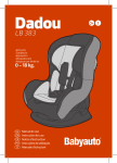
OMPI System Diagram
L1 Oxygen sensor
L2 Air flow sensor
L3 Intake air temperature sensor
L4 Throttle position sensor
L5 Idle switch
L6 Camshaft position sensor
L7 Crank angle sensor
L8 Barometric pressure sensor
L9 High temperature sensor
L10 Engine coolant temperature sensor
L11 Detonation sensor
D
D
D
D
D
D
D
Engine ECU
Power supply voltage
Ignition switch-IG
Ignition switch-ST
Vehicle speed sensor
A/C switch
Power steering fluid pressure switch
Alternator FR signal
l5
Canister
Check valve
Secondary air
control solenoid
valve
From
fuel
tank
l2
l1
l2
l3
l4
l5
Injector
ISC servo
Fuel pressure control valve
Waste gate solenoid valve
Secondary air control solenoid valve
D
D
D
D
D
D
D
D
D
D
D
Control relay
Fuel pump relay
A/C relay
Ignition coil
Exhaust temperature warning lamp
Engine warning lamp
Diagnosis output
Alternator G terminal
Fan motor relay
Tachometer
Fuel pump relay No.2
ISC servo
Throttle position
sensor (with a
built-in
idle
switch)
L4,
L5
Secondary
air valve
L8
L2
Barometric
pressure sensor L3
Intake air temAir flow sensor
To fuel
tank
L1 Oxygen sensor
Fuel
pressure
regulator
From
fuel
pump
Fuel pressure
control valve
L6
Camshaft position
sensor
l1 Injector
perature sensor
Air
l3
L10 Coolant temperature sensor
Waste gate
actuator
l4
Waste gate
solenoid valve
L7 Crank angle sensor
L11 Detonation sensor
L9
High temperature
sensor
Catalytic converter
Given above is the MPI system diagram for EVOLUTION-IV. The MPI system for EVOLUTION-V is different
from this in the following point;
D Oxygen sensor with a heater is adopted.
D The diagnosis connector power supply circuit is different.
D The high temperature sensor is no longer used.
13-3
MPI – Service Specifications / Sealant
SERVICE SPECIFICATIONS
Items
Specifications
5±3
Basic ignition timing _BTDC
850 ± 50
Basic idle speed rpm
Throttle position sensor adjusting voltage mV
400 – 1,000
Throttle position sensor resistance kΩ
3.5 – 6.5
ISC servo coil resistance (at 20_C) Ω
28 – 33
Intake air temperature sensor resistance kΩ
Coolant temperature sensor resistance kΩ
Fuel pressure
kPa {kgf/cm2}
At 20_C
2.3 – 3.0
At 80_C
0.30 – 0.42
At 20_C
2.1 – 2.7
At 80_C
0.26 – 0.36
When vacuum hose is connected
When vacuum hose is disconnected
Injector coil resistance Ω
230 {2.35}
289 – 309 {2.95 – 3.15}
2–3
Amount of injector fuel leak drop/min
1 or less
Oxygen sensor output voltage
0.6 – 1.0
Fuel pressure control valve coil resistance (at 20_C) Ω
28 – 36
SEALANT
Item
Specified sealant
Coolant temperature sensor
Drying sealant: HELMESEAL H-1M [0110513]
NOTE:
Given in [ ] are MITSUBISHI GENUINE PART numbers.
13-4
MPI – Special Tools
SPECIAL TOOLS
Tool
Number
Name
Use
MB991348
Test harness set
D
D
Measurement of voltage during troubleshooting
Inspection using an oscilloscope
MB991519
Alternator harness
connector
Measurement of voltage during
troubleshooting
MB991536
TPS check
harness
Adjustment of idle switch and throttle position
sensor (TPS)
MD998464
Test harness
(4-pin, square)
Inspection of oxygen sensor
MD998463
Test harness
(6-pin, square)
D
D
Inspection of idle speed control servo
Inspection using an oscilloscope
MD998478
Test harness
(3-pin, triangle)
D
Measurement of voltage during troubleshooting
Inspection using an oscilloscope
MD998706
Injector test set
Checking the spray condition of injectors
MD998741
Injector test
adaptor
MB991607
Injector test
harness
D
13-5
MPI – Special Tools
Tool
Number
Name
Use
MD998746
Clip
Checking the spray condition of injectors
MD998709
Adaptor hose
Measurement of fuel pressure
MD998742
Hose adaptor
MB991637
Fuel pressure
gauge set
MB991223
Inspection test
herness set
D Pin contact
pressure
inspection
harness
D Market tester
contact probe
(for general
connectors)
Measurement of terminal voltage
MB991529
Diagnostic trouble
code check harness
Reading of diagnosis codes
MB991709
Test harness
D
Red harness
White harness
D
Measurement of voltage during troubleshooting
Inspection using an oscilloscope
13-6
MPI – Troubleshooting
TROUBLESHOOTING
1. DIAGNOSIS FUNCTION
Engine warning lamp
(check engine lamp)
1-1 ENGINE WARNING LAMP (CHECK ENGINE LAMP)
If an abnormality occurs in any of the following items related
to the Multipoint Fuel Injection (MPI) system, the engine
warning lamp will illuminate.
If the lamp remains illuminated or if the lamp illuminates while
the engine is running, check the diagnosis code output.
Engine warning lamp inspection items
Engine-ECU
Air flow sensor (AFS)
Intake air temperature sensor
Throttle position sensor (TPS)
Engine coolant temperature sensor
Crank angle sensor
Camshaft position sensor
Barometric pressure sensor
Detonation sensor
Injector
Ignition coil, power transister
Misfire <Evolution-V only>
1-2 METHOD OF READING AND ERASING DIAGNOSIS
CODES
(1) Use the special tool to earth No.1 terminal (diagnosis
control terminal) of the diagnosis connector.
(2) To check ABS system, remove the valve relay.
NOTE
That is because the valve relay is off and the warning
lamp remains illuminated if there is a fault in the ABS
system.
(3) Turn off the ignition switch.
(4) Read out a diagnosis code by observing how the warning
lamp flashes.
Indication of diagnosis code by warning lamp
When the diagnosis code No.24 is output
When no diagnosis code is output*
0.5 sec.
1.5 secs.
0.5 sec.
0.5 sec. <MPI, A/T>
0.25 sec. <ABS>
On
Off
Pause
time 3
secs.
Tens signal
Place
Units signal
division
A03X0113
2 secs.
On
Off
NOTE
*: Even if the ABS system is normal, removing the valve relay causes the diagnosis code No.52 to
be output.
MPI – Troubleshooting
13-7
1-3 ERASING DIAGNOSIS CODES
(1) Turn the ignition switch to OFF.
(2) After disconnecting the battery cable from the battery (–) terminal for 10 seconds or more, reconnect
the cable.
(3) After the engine has warmed up, run it at idle for about 15 minutes.
1-4 FAIL-SAFE FUNCTION REFERENCE TABLE
When the main sensor malfunctions are detected by the diagnosis function, the vehicle is controlled
by means of the pre-set control logic to maintain safe conditions for driving.
Malfunctioning item
Control contents during malfunction
Air flow sensor (AFS)
(1) Uses the throttle position sensor signal and engine speed signal (crank angle sensor
signal) to take reading of the basic injector drive time and basic ignition timing from
the pre-set mapping.
(2) Fixes the ISC servo in the appointed position so idle control is not performed.
Intake air temperature
sensor
Controls as if the intake air temperature is 25_C.
Throttle position
sensor (TPS)
No increase in fuel injection amount during acceleration due to the throttle position sensor
signal.
Engine coolant
temperature sensor
Controls as if the engine coolant temperature is 80_C.
(This condition is maintained until the ignition switch is turned off even when the sensor signal
returns normal.)
Camshaft position
sensor
(1) Injects fuel to all cylinders simultaneously for 4 seconds.
(However, after the ignition switch is turned to ON, the No. 1 cylinder top dead centre
is not detected at all.)
(2) Lets the fan motor (radiator and condensor) run at high speed.
Barometric pressure
sensor
Controls as if the barometric pressure is 101 kPa {760 mmHg}.
Detonation sensor
Switches the ignition timing from ignition timing for super petrol to ignition timing for standard
petrol.
Ignition coil, power
transistor
Cuts off the fuel supply to cylinders with an abnormal ignition.
Alternator FR terminal
Does not control the output of the alternator according to an electrical load. (works as a
normal alternator)
Misfire
(Evolution-V only)
Cuts off the fuel to the misfiring cylinder if a misfire that could damage the catalyst is detected.
13-8
MPI – Troubleshooting
2. INSPECTION CHART FOR DIAGNOSIS CODES
Code No.
Diagnosis item
Reference page
12
Air flow sensor (AFS) system
13-8
13
Intake air temperature sensor system
13-9
14
Throttle position sensor (TPS) system
13-9
21
Engine coolant temperature sensor system
13-10
22
Crank angle sensor system
13-11
23
Camshaft position sensor system
13-11
24
Vehicle speed sensor system
13-12
25
Barometric pressure sensor system
13-13
31
Detonation sensor system
13-14
41
Injector system
13-14
44
Ignition coil and power transistor unit system
13-15
64
Alternator FR terminal system
13-16
3. INSPECTION PROCEDURE FOR DIAGNOSIS CODES
Code No. 12 Air flow sensor (AFS) system
Probable cause
Range of Check
D Engine speed is 500 r/min or more.
Set conditions
D Sensor output frequency is 3 Hz or less for 4 seconds.
D Malfunction of the air flow sensor
D Improper connector contact, open circuit or
short-circuited harness wire of the air flow sensor
D Malfunction of the engine-ECU
1. NG
Measure at the air flow sensor conCheck the air flow sensor circuit.
nector A-25.
D Connect the connector. (Use
the test harness: MB991709) 2. NG
NG
Measure at the engine-ECU con1. Voltage between 3 and earth
nector B-59.
(Engine: Idling)
D Connect the connector.
OK: 2.2– 3.2 V
D Voltage between 19 and earth
2. Voltage between 7 and earth
(Ignition switch: ON)
OK: 0 – 1 V (Engine: idling)
OK: 6 – 9 V
6 – 9 V (2,000 r/min)
OK
OK
Check trouble symptom.
NG
OK
NG
Replace the engine-ECU.
Check the following connector:
A-25
Check the following connector:
B-59
OK
Check trouble symptom.
NG
Replace the engine-ECU.
Repair
Replace the air flow sensor.
NG
Repair
13-9
MPI – Troubleshooting
Code No. 13 Intake air temperature sensor system
Probable cause
Range of Check
D Ignition switch: ON
D Excluding 60 seconds after the ignition switch is turned to ON or immediately
after the engine starts.
Set conditions
D Sensor output voltage is 4.6 V or more (corresponding to an intake air temperature
of –45_C or less) for 4 seconds.
or
D Sensor output voltage is 0.2V or less (corresponding to an intake air temperature
of 125_C or more) for 4 seconds.
D Malfunction of the intake air temperature sensor
D Improper connector contact, open circuit or
short-circuited harness wire of the intake air
temperature sensor circuit
D Malfunction of the engine-ECU
Check the intake air temperature sensor. (Refer to P.13-32.)
NG
Replace air flow sensor.
OK
Measure at the air flow sensor connector A-25.
D Disconnect the connector, and
measure at the harness side.
D Voltage between 6 and earth
(Ignition switch: ON)
OK: 4.5– 4.9 V
D Continuity between 5 and earth
OK: Continuity
NG
Repair
OK
Check trouble symptom.
NG
Check the harness wire between the
engine-ECU and the intake air temperature sensor connector.
OK
Check the following connector:
A-25
NG
Check the following connector:
C-62
NG
NG
Repair
OK
Repair
OK
Check trouble symptom.
NG
Replace the engine-ECU.
Code No. 14 Throttle position sensor (TPS) system
Probable cause
Range of Check
D Ignition switch: ON
D Excluding 60 seconds after the ignition switch is turned to ON or immediately
after the engine starts.
Set conditions
D The sensor output voltage is 0.2 V or less for 4 seconds.
D Malfunction of the throttle position sensor
D Improper connector contact, open circuit or
short-circuited harness wire of the throttle position
sensor circuit
D Improper “ON” state of idle position switch
D Short circuit of the idle position switch signal line
D Malfunction of the engine-ECU
Check the throttle position sensor.
NG
Replace
OK
Measure at the throttle position sensor
connector A-16.
D Disconnect the connector, and
measure at the harness side.
D Voltage between 1 and earth
(Ignition switch: ON)
OK: 4.8– 5.2 V
D Continuity between 4 and earth
OK: Continuity
OK
Check the throttle position sensor output circuit.
NG
Check the following connector:
B-62
NG
Repair
OK
Check trouble symptom.
NG
Check the harness wire between the
engine-ECU and the throttle position
sensor connector.
OK
Replace the engine-ECU.
NG
Repair
13-10
MPI – Troubleshooting
Code No. 21 Engine coolant temperature sensor system
Probable cause
Range of Check
D Ignition switch: ON
D Excluding 60 seconds after the ignition switch is turned to ON or immediately
after the engine starts.
Set conditions
D Sensor output voltage is 4.6 V or more (corresponding to an engine coolant
temperature of –45_C or less) for 4 seconds.
or
D Sensor output voltage is 0.1 V or less (corresponding to an engine coolant
temperature of 140_C or more) for 4 seconds.
D Malfunction of the engine coolant temperature sensor
D Improper connector contact, open circuit or
short-circuited harness wire of the engine coolant
temperature sensor circuit
D Malfunction of the engine-ECU
Range of Check
D Ignition switch: ON
D Engine speed is approx. 50 r/min or more
Set conditions
D The sensor output voltage increases from 1.6 V or less (corresponding to an
engine coolant temperature of 40_C or more) to 1.6 V or more (corresponding
to an engine coolant temperature of 40_C or less).
D After this, the sensor output voltage is 1.6 V or more for 5 minutes.
Check the engine coolant temperature
sensor. (Refer to P.13-32.)
NG
Replace
OK
Measure at the engine coolant temperature sensor connector A-38.
D Disconnect the connector, and
measure at the harness side.
D Voltage between 1 and earth
(Ignition switch: ON)
OK: 4.5– 4.9 V
D Continuity between 2 and earth
OK: Continuity
NG
Repair
Check trouble symptom.
NG
Check the harness wire between the
engine-ECU and the engine coolant
temperature sensor connector.
OK
NG
Repair
OK
Check trouble symptom.
NG
OK
OK
Check the following connector:
A-38
Check the following connector:
B-62
NG
Replace the engine-ECU.
NG
Repair
13-11
MPI – Troubleshooting
Code No. 22 Crank angle sensor system
Probable cause
Range of Check
D Engine is cranking.
Set conditions
D Sensor output voltage does not change for 4 seconds (no pulse signal input.)
D Malfunction of the crank angle sensor
D Improper connector contact, open circuit or
short-circuited harness wire of the crank angle sensor
D Malfunction of the engine-ECU
OK
Measure at the crank angle sensor connector A-51.
D Connect the connector. (Use the test harness: MD998478.)
D Voltage between 2 (black clip) and earth (Engine: cranking)
OK: 0.4– 4.0 V
D Voltage between 2 (black clip) and earth (Engine: idling)
OK: 1.5– 2.5 V
Replace the engine-ECU.
NG
1. NG
Measure at the crank angle sensor connector A-51.
D Disconnect the connector, and measure at the harness side.
1. Voltage between 3 and earth (Ignition switch: ON)
2. NG
OK: System voltage
2. Voltage between 2 and earth (Ignition switch: ON)
OK: 4.8– 5.2 V
3. NG
3. Continuity between 1 and earth
OK: Continuity
OK
Check the following connector: A-51
Check the harness wire between the crank angle sensor and the
control relay connector, and repair if necessary.
Check the following connector: B-62
NG
Repair
OK
Check trouble symptom.
NG
NG
Repair
Check the harness wire
betweenthe engine-ECU and
the crank angle sensor
connector.
OK
Check trouble symptom.
NG
Repair
OK
NG
Replace the engine-ECU.
Replace the crank angle sensor.
Check the harness wire between the crank angle sensor and the
earth, and repair if necessary.
Code No. 23 Camshaft position sensor system
Probable cause
Range of Check
D Ignition switch: ON
D Engine speed is approx. 50 r/min or more.
Set conditions
D Sensor output voltage does not change for 4 seconds (no pulse signal input.)
D Malfunction of the camshaft position sensor
D Improper connector contact, open circuit or
short-circuited harness wire of the camshaft position
sensor circuit
D Malfunction of the engine-ECU
OK
Measure at the camshaft position sensor connector A-97.
D Connect the connector.
D Voltage between 2 and earth (Engine: cranking)
OK: 0.4– 3.0 V
D Voltage between 2 and earth (Engine: idling)
OK: 0.5– 2.0 V
Replace the engine-ECU.
NG
1. NG
Measure at the camshaft position sensor connector A-97.
D Disconnect the connector, and measure at the harness side.
1. Voltage between 3 and earth (Ignition switch: ON)
2. NG
OK: System voltage
2. Voltage between 2 and earth (Ignition switch: ON)
OK: 4.8– 5.2 V
3. NG
3. Continuity between 1 and earth
OK: Continuity
OK
Check the following connector: A-97
Check trouble symptom.
NG
Replace the camshaft position sensor.
Check the following connector: B-62
NG
Repair
OK
Check trouble symptom.
NG
NG
OK
Check the harness wire between the camshaft position sensor
and the control relay connector, and repair if necessary.
Repair
Check the harness wire
betweenthe engine-ECU and
the camshaft position sensor
connector.
NG
Repair
OK
Replace the engine-ECU.
Check the harness wire between the camshaft position sensor
and the earth, and repair if necessary.
13-12
MPI – Troubleshooting
Code No. 24 Vehicles speed sensor system
Probable cause
Range of check
D Ignition switch: ON
D Excluding 60 seconds after the ignition switch is turned to ON or immediately
after the engine starts.
D Idle position switch: OFF
D Engine speed is 3,000 r/min or more.
D Driving under high engine load conditions.
Set conditions
D Sensor output voltage does not change for 4 seconds (no pulse signal input).
D Malfunction of the vehicle speed sensor
D Improper connector contact, open circuit or
short-circuited harness wire of the vehicle speed
sensor circuit
D Malfunction of the engine-ECU
Check the vehicle speed sensor. (Refer to GROUP 54 – Combination Meters.)
NG
Replace
OK
1. NG
Measure at the vehicle speed sensor connector A-19.
D Disconnect the connector, and measure at the harness side.
1. Voltage between 1 and earth (Ignition switch: ON)
2. NG
OK: System voltage
2. Voltage between 3 and earth (Ignition switch: ON)
OK: 4.8 – 5.2 V
3. NG
3. Continuity between 2 and earth
OK: Continuity
OK
NG
Check the following
connectors:
A-19, B-62
Repair
Check the following
connectors:
B-64, B-74, B-76
NG
Repair
OK
Check trouble symptom.
NG
NG
Check the harness wire
between the vehicle
speed sensor and ignition
switch connector.
OK
Repair
OK
Check the ignition switch. (Refer to GROUP 54 – Ignition Switch.)
Check trouble symptom.
NG
NG
Check the harness wire
between the engine-ECU
and the vehicle speed
sensor connector.
OK
Replace the engine-ECU.
Repair
Check the
connector:
B-62
following
NG
Repair
OK
Check trouble symptom.
NG
NG
Check the harness wire
between the engine-ECU
and the vehicle speed
sensor connector.
OK
Repair
Replace the engine-ECU.
Check the harness wire between the vehicle speed sensor and
the earth, and repair if necessary.
13-13
MPI – Troubleshooting
Code No. 25 Barometric pressure sensor system
Probable cause
Range of Check
D Ignition switch: ON
D Excluding 60 seconds after the ignition switch is turned to ON or immediately
after the engine starts.
Set conditions
D Sensor output voltage is 4.5 V or more (corresponding to a barometric pressure
of 114 kPa {855 mmHg} or more) for 4 seconds.
or
D Sensor output voltage is 0.2 V or less (corresponding to a barometric pressure
of 53 kPa {40 mmHg} or less) for 4 seconds.
D Malfunction of the barometric pressure sensor
D Improper connector contact, open circuit or
short-circuited harness wire of the barometric pressure
sensor circuit
D Malfunction of the engine-ECU
Measure at the air flow sensor connector A-25.
D Connect the connector. (Use
the test harness: MB991709)
D Voltage between 2 and earth
(Ignition switch: ON)
OK: 3.7– 4.3 V (Altitude: 0 m)
3.2– 3.8 V
(Altitude: 1,200 m)
NG
Measure at the air flow sensor connector A-25.
D Disconnect the connector, and
measure at the harness side.
D Voltage between 1 and earth
(Ignition switch: ON)
OK: 4.8– 5.2 V
D Continuity between 5 and earth
OK: Continuity
NG
Check the following connector:
A-25
Measure at the engine-ECU connector B-62.
D Connect the connector.
D Voltage between 85 and earth
(Ignition switch: ON)
OK: 3.7– 4.3 V (Altitude: 0 m)
3.2– 3.8 V
(Altitude: 1,200 m)
NG
Check the harness wire between
the engine-ECU and the barometric pressure sensor connector, and
repair if necessary.
OK
Check the following connectors:
A-25, B-62
OK
Check trouble symptom.
NG
Replace the engine-ECU.
NG
Repair
Repair
Check trouble symptom.
NG
Check the harness wire between
the engine-ECU and the barometric pressure sensor connector.
NG
OK
Check trouble symptom.
NG
OK
OK
OK
Check the following connector:
B-62
NG
Repair
OK
Repair
Replace the engine-ECU.
NG
Check the harness wire between
the engine-ECU and the barometric pressure sensor connector.
OK
Replace the air flow sensor.
NG
Repair
13-14
MPI – Troubleshooting
Code No.31 Detonation sensor system
Probable cause
Range of Check
D Ignition switch: ON
D Excluding 60 seconds after the ignition switch is turned to ON or immediately
after the engine starts.
D Engine speed is approx. 5,000 r/min or more
Set conditions
The change in the detonation sensor output voltage (detonation sensor peak voltage
at each 1/2 revolution of the crankshaft) is less than 0.06 V for 200 times in succession.
D Malfunction of the detonation sensor
D Improper connector contact, open circuit or
short-circuited harness wire of the detonation sensor
circuit
D Malfunction of the engine-ECU
Measure at the detonation sensor connector A-96.
D Disconnect the connector and
measure at the harness side.
D Continuity between 2 and earth
OK: Continuity
OK
NG
Check the following connector:
B-62
Repair
OK
Check trouble symptom.
NG
NG
Check the harness wire between the
engine-ECU and the detonation sensor
connector.
Check the harness wire between the
detonation sensor and earth, and repair
if necessary.
OK
Replace the detonation sensor.
Check trouble symptom.
NG
NG
Repair
Replace the engine-ECU.
Code No. 41 Injector system
Probable cause
Range of Check
D Engine speed is approx. 50 – 1,000 r/min
D The throttle position sensor output voltage is 1.15 V or less.
Set conditions
D Surge voltage of injector coil is not detected for 4 seconds.
D Malfunction of the injector
D Improper connector contact, open circuit or
short-circuited harness wire of the injector circuit
D Malfunction of the engine-ECU
Check the injector. (Refer to P.13-34.)
Check the resistor. (Refer to P.13-34.)
NG
Replace
OK
Measure at the resistor connector
A-125.
D Disconnect the connector, and
measure at the harness side.
D Voltage between 3 and earth
(Ignition switch: ON)
OK: System voltage
NG
Check the harness wire between the
control relay and the resistor connector, and repair if necessary.
OK
Measure at the injector connectors
A-53, A-54, A-55, A-56.
D Disconnect the connector, and
measure at the harness side.
D Voltage between 1 and earth
(Ignition switch: ON)
OK: System voltage
OK
Check the injector control circuit.
NG
Check the following connector:
A-125
OK
Check trouble symptom.
NG
Check the harness wire between the
resistor and the injector connector, and
repair if necessary.
NG
Repair
13-15
MPI – Troubleshooting
Code No. 44 Ignition coil and power transistor unit system
Probable cause
Range of Check
D Engine speed is approx. 50 – 4,000 r/min.
D Engine is not being cranked.
Set conditions
D Abnormal engine speed is detected due to misfiring by crank angle sensor. (One
of two coils fails.)
D Malfunction of the ignition coil
D Improper connector contact, open circuit or
short-circuited harness wire of the ignition primary
circuit
D Malfunction of the engine-ECU.
Check the ignition coil. (Refer to Group 16 – Ignition System.)
NG
Replace
OK
Measure at the ignition coil connectors A-110, A-111.
D Disconnect the connector, and measure at the harness.
1. Voltage between 1 and earth (Ignition switch: ON)
OK: System voltage
2. Voltage between 3 and earth (Engine: Cranking)
OK: 0.5 – 4.0 V
3. Continuity between 2 and earth
OK: Continuity
OK
NG
Check the following
connectors:
A-110, A-111
Repair
OK
Check trouble symptom.
NG
Check the following items.
D Check the spark plugs and spark plug cables.
D Check the compression pressure.
1. NG
2. NG
3. NG
Check the following
connectors:
B-65, B-76
NG
Repair
OK
Check trouble symptom.
NG
Check the harness wire between the ignition coil and ignition switch
connector, and repair if necessary.
Check the
connector:
B-59
following
NG
Repair
OK
Check trouble symptom.
NG
NG
Check the harness wire
between the engine-ECU
and ignition coil connector.
OK
Repair
Replace the engine-ECU.
Check the harness wire between the ignition coil connector and
earth, and repair if necessary.
13-16
MPI – Troubleshooting
Code No. 64 Alternator FR Terminal System
Probable cause
Range of Check
D Engine speed is approximately 50 r/min or more.
Set conditions
D Input voltage at the alternator FR terminal is 4.5 V or more for 20 seconds.
D Open circuit in alternator FR terminal circuit
D Malfunction of the engine-ECU.
Measure at the alternator connector
D Connect the connector.
(Use test harness MB991519.)
D Voltage between 4 (blue clip)
and earth
(Engine: Idling)
(Radiator fan: Stopped)
(Headlamp: OFF → ON)
(Brake lamp: OFF → ON)
(Rear defogger switch: OFF
→ ON)
OK: Voltage drops by 0.2 to
3.5 V.
OK
Replace the engine-ECU.
NG
Measure at the alternator connector A-05.
D Disconnect the connector, and
measure at the harness side.
D Voltage between 4 and earth
(Ignition switch: ON)
OK: 4.8 – 5.2 V
NG
Check the following connectors:
B-60, A-88
Check trouble symptom.
NG
Check the harness wire between
the engine-ECU and alternator
connector.
NG
OK
OK
Repair
Replace the engine-ECU.
Check trouble symptom.
NG
Check the harness wire between
the engine-ECU and alternator
connector.
OK
Replace the alternator.
Repair
OK
OK
Check the following connector:
A-05
NG
NG
Repair
NG
Repair
13-17
MPI – Troubleshooting
4. PROBLEM SYMPTOMS TABLE
Items
Symptom
Starting
Idling
stability
Driving
Stopping
Won’t start
The starter is used to crank the engine, but there is no combustion within the
cylinders, and the engine won’t start.
Fires up and dies
There is combustion within the cylinders, but then the engine soon stalls.
Hard starting
Engine starts after cranking a while.
Rough idle
Hunting
Engine speed doesn’t remain constant and changes at idle.
Usually, a judgement can be based upon the movement of the tachometer
pointer, and the vibration transmitted to the steering wheel, shift lever, body, etc.
This is called rough idle or hunting.
Incorrect idle speed
The engine doesn’t idle at the usual correct speed.
Engine stall
(Die out)
The engine stalls when the accelerator pedal is released, regardless of whether
the vehicles is moving or not.
Engine stall
(Pass out)
The engine stalls when the accelerator pedal is depressed or while it is being
used.
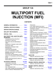
Hesitation, Sag
“Hesitation” is the delay in response of the vehicle speed (engine speed) that
occurs when the accelerator is depressed in order to accelerate from the speed
at which the vehicle is now traveling, or a temporary drop in vehicle speed
(engine speed) during such acceleration. Serious hesitation is called “sag”.
(Refer to Figure 1.)
Poor acceleration
Poor acceleration is inability to obtain an acceleration corresponding to the
degree of throttle opening, even though acceleration is smooth, or the inability
to reach maximum speed.
Stumble
Engine speed increase is delayed when the accelerator pedal is initially
depressed for acceleration. (Refer to Figure 2.)
Shock
The feeling of a comparatively large impact or vibration when the engine is
accelerated or decelerated.
Surge
This is repeated forward or rearward surging during constant speed travel or
during variable speed travel.
Knocking
A sharp sound like a hammer striking the cylinder walls during driving and which
adversely affects driving.
Run on
(“Dieseling”)
The condition in which the engine continues to run after the ignition switch is
turned to OFF. Also called “Dieseling”.
(Figure 1)
Hesitation
(Figure 2)
Normal
Vehicle
speed
Vehicle Initial accelspeed
erator pedal
depression
Sag
Time
Normal
Initial accelerator pedal
depression
Idling
Stumble
Time
13-18
MPI – Troubleshooting
5. SERVICE DATA LIST
<EVOLUTION-IV>
Item
No.
Inspection
item
Inspection contents
11
Oxygen
sensor
Engine: After having been warmed
up
Air/fuel mixture is made leaner when
decelerating, and is made richer
when racing.
When at 4,000 r/min, engine is
suddenly decelerated
200 mV or less
When engine is suddenly
raced
600 – 1,000 mV
Engine: After having been warmed
up
The oxygen sensor signal is used to
check the air/fuel mixture ratio, and
control condition is also checked by
the ECU.
Engine is idling
400 mV or less
D
Engine is idling
17 – 43 Hz
2,500 r/min
46 – 86 Hz
Engine is raced
Frequency increases
in response to racing
When intake air temperature
is –20_C
–20_C
When intake air temperature
is 0_C
0_C
When intake air temperature
is 20_C
20_C
When intake air temperature
is 40_C
40_C
When intake air temperature
is 80_C
80_C
Set to idle position
300 – 1,000 mV
Gradually open
Increases in proportion
to throttle opening
angle
Open fully
4,500 – 5,500 mV
12
Air flow
sensor*
D
D
13
14
Intake air
temperature
sensor
Throttle
position
sensor
Engine coolant temperature:
80 – 95_C
Lamps, electric cooling fan and
all accessories: OFF
Transmission: Neutral
Ignition switch: ON or with engine
running
Ignition switch: ON
16
Power
supply
voltage
Ignition switch: ON
18
Cranking
g
signal
(ignition
switch-ST)
Ignition switch: ON
Normal condition
(Changes)
2,500 r/min
600 – 1,000 mV
System voltage
Engine: Stopped
OFF
Engine: Cranking
ON
NOTE
*: When the car is new (distance it travelled is less than 500 km), output frequency of the air flow sensor may
become about 10% higher.
13-19
MPI – Troubleshooting
Item
No.
Inspection
item
Inspection contents
21
Engine
coolant
temperature
sensor
Ignition switch: ON or with engine
running
22
25
26
27
28
Normal condition
When engine coolant temperature is –20_C
–20_C
When engine coolant temperature is 0_C
0_C
When engine coolant temperature is 20_C
20_C
When engine coolant temperature is 40_C
40_C
When engine coolant temperature is 80_C
80_C
When engine coolant temperature is –20_C
1,300 – 1,500 rpm
When engine coolant temperature is 0_C
1,300 – 1,500 rpm
When engine coolant temperature is 20_C
1,300 – 1,500 rpm
When engine coolant temperature is 40_C
1,150 – 1,350 rpm
When engine coolant temperature is 80_C
750 – 950 rpm
At altitude of 0 m
101 kPa
At altitude of 600 m
95 kPa
At altitude of 1,200 m
88 kPa
At altitude of 1,800 m
81 kPa
Throttle valve: Set to idle
position
ON
Throttle valve: Slightly open
OFF* 1
Power
Engine: Idling
steering
t
g fluid
pressure
switch
Steering wheel stationary
OFF
Steering wheel turning
ON
A/C switch
A/C switch: OFF
OFF
A/C switch: ON
ON
Crank angle
sensor
Barometric
pressure
sensor
Idle position
switch
D
D
Engine: Idling
Idle position switch: ON
Ignition switch: ON
Ignition switch: ON
(Check by operating accelerator
pedal
d l repeatedly.)
t dl )
Engine: Idling
(when A/C switch is ON,
ON A/C
compressor should be operating.)
13-20
MPI – Troubleshooting
Item
No.
Inspection
item
Inspection contents
41
Injector
drive time*2
Engine: Cranking
Injector
drive time*3
D
D
D
44
45
49
Ignition
advance
ISC
(stepper)
motor
position *4
A/C relay
D
D
D
D
D
D
D
Normal condition
When engine coolant temperature is 0_C (injection is
carried out for all cylinders
simultaneously)
27 – 41 ms
When engine coolant temperature is 20_C
14 – 22 ms
When engine coolant temperature is 80_C
3.9 – 5.9 ms
Engine coolant temperature:
80 – 95_C
Lamps, electric cooling fan and
all accessories: OFF
Transmission: Neutral
Engine is idling
1.2 – 2.4 ms
2,500 r/min
1.0 – 2.2 ms
When engine is suddenly
raced
Increases
Engine: After having
warmed up
Timing lamp is set.
set (The
lamp is set in order to
actual ignition timing.)
Engine is idling
3 – 13_BTDC
2,500 r/min
24 – 44_BTDC
been
timing
check
Engine coolant temperature:
A/C switch: OFF
80 – 90_C
Lamps electric cooling fan and
Lamps,
all accessories: OFF
A/C switch: OFF → ON
Transmission: Neutral
Idle position switch: ON
Engine: Idling
(When A/C switch is ON, A/C A/C switch: OFF
compressor should be operating.)
Engine: After having been warmed
up/Engine is idling
2 – 25 steps
Increases by 10 – 70
steps
Increases by 5 – 50
steps
A/C switch: OFF
OFF (Compressor
clutch is not operating)
A/C switch: ON
ON (Compressor
clutch is operating)
NOTE
*1: The idle position switch normally turns off when the voltage of the throttle position sensor is 50 – 100 mV
higher than the voltage at the idle position. If the idle position switch turns back on after the throttle valve
is opened, the idle position switch and the throttle position sensor need to be adjusted.
*2: The injector drive time represents the time when the cranking speed is at 250 r/min or below when the power
supply voltage is 11 V.
*3: In a new vehicle [driven approximately 500 km or less], the injector drive time is sometimes 10% longer than
the standard time.
*4: In a new vehicle [driven approximately 500 km or less], the step of the stepper motor is sometimes 30 steps
greater than the standard value.
13-21
MPI – Troubleshooting
<EVOLUTION-V>
Descriptions other than those given below are the same as for the EVOLUTION-IV.
Item
No.
Inspection
item
Inspection contents
Normal condition
12
Air flow
sensor*1
D
12 – 38 Hz
D
D
41
Injector
drive time*2
Injector
drive time *3
Engine: Cranking*2
D
D
D
44
Ignition
advance
Engine coolant temperature:
Engine is idling
80 – 95_C
Lamps, electric cooling fan and 2,500 r/min
all accessories: OFF
Engine is raced
Transmission: Neutral
D
D
36 – 76 Hz
Frequency increases
in response to racing
When engine coolant temperature is 0_C
27 – 40 ms
When engine coolant temperature is 20_C
14.5 – 21.7 ms
When engine coolant temperature is 80_C
3.8 – 5.6 ms
Engine coolant temperature:
Engine is idling
80 – 95_C
Lamps, electric cooling fan and 2,500 r/min
all accessories: OFF
When engine is suddenly
Transmission: Neutral
raced
0.9 – 2.1 ms
Engine: After having
warmed up
Timing lamp is set.
0 – 13_BTDC
been Engine is idling
2,500 r/min
0.7 – 1.9 ms
Increases
24 – 44_BTDC
NOTE
*1: In a new vehicle (driven approximately 500 km or less), the air flow sensor output frequency is sometimes
10 % higher than the standard frequency.
*2: The injector drive time represents the time when the cranking speed is at 250 r/min or below when the power
supply voltage is 11 V.
*3: In a new vehicle (driven approximately 500 km or less), the injector drive time is sometimes 10 % longer than
the standard time.
13-22
MPI – Troubleshooting
6. ENGINE-ECU INSPECTION
6-1 TERMINAL VOLTAGES
Engine ECU connector
Terminal
No.
Check item
Check condition (Engine condition)
Normal condition
1
No.1 injector
While engine is idling after having been warmed up,
pedal
suddenly depress the accelerator pedal.
Momentarily drops
V
slightly from 11 – 14 V.
14
No.2 injector
2
No.3 injector
15
No.4 injector
3
Fuel pressure control
valve
Ignition switch: ON
Battery voltage
Engine: Cranking to idling (within about two minutes)
0 – 3 V to battery
voltage
Engine: Immediately after engine has been started
for warming up
Changes repeatedly
from battery voltage to
0 – 6 V and from 0 – 6
V to battery voltage.
voltage
4
Stepper motor coil (A1)
17
Stepper motor coil (A2)
5
Stepper motor coil (B1)
18
Stepper motor coil (B2)
6
Secondary air control
solenoid valve
Ignition switch: ON
Battery voltage
8
Fuel pump relay
Ignition switch: ON
Battery voltage
Engine: Idling
0–3V
Engine speed: 3,000 r/min
0.3 – 3.0 V
Ignition switch: ON
Battery voltage
Engine: At idle after having been warmed up (when
premium gasoline is used)
0–3V
Power supply
Ignition switch: ON
Battery voltage
Air flow sensor reset
signal
Engine: Idling
0–1V
Engine speed: 3,000 r/min
6–9V
Fan not operating (coolant temperature: 90_C or
below)
Battery voltage
Fan at high speed (coolant temperature: 105_C or
above)
0–3V
10
Power transistor unit
(A)
23
Power transistor unit
(B)
11
Wastegate solenoid
valve
12
25
19
20
Fan motor relay (HI)
13-23
MPI – Troubleshooting
Terminal
No.
Check item
Check condition (Engine condition)
Normal condition
21
Fan motor relay (LOW)
Fan not operating (coolant temperature: 90_C or
below)
Battery voltage
Fan at low speed (coolant temperature: 90 – 100_C)
0–3V
22
A/C relay
D
D
Engine: Idling
A/C switch: OFF to ON (Compressor is being
driven.)
Battery voltage, or 6 V
or more instantaneously to 0 – 3 V
33
Alternator G terminal
D
D
D
D
Engine: Warm, idle (radiator fan: OFF)
Headlamp: OFF to ON
Brake lamp: OFF to ON
Rear defogger switch: OFF to ON
Voltage rises by 0.2 –
3.5 V.
36
Engine warning lamp
Ignition switch: OFF → ON
0 – 3 V → Battery
voltage (After several
seconds have
elapsed)
37
Power steering fluid
pressure switch
Engine: Idling
warming up
When steering wheel is
stationary
Battery voltage
When steering wheel is
turned
0–3V
38
Control relay
after
Ignition switch: OFF
Battery voltage
Ignition switch: ON
0–3V
39
Fuel pump relay No.2
While engine is idling, suddenly depress the
accelerator pedal.
Momentarily rises
slightly from 0 to 3 V.
40
Exhaust temperature
warning lamp
Ignition switch: OFF to ON
0 – 3 V to battery
voltage (After several
seconds have
elapsed)
41
Alternator FR terminal
D
D
D
D
Voltage drops by 0.2 –
3.5 V.
45
A/C switch
Engine: Idle speed
60
71
Oxygen sensor heater
(Evolution V only)
(Evolution-V
Ignition switch-ST
Engine: Warm, idle (radiator fan: OFF)
Headlamp: OFF to ON
Brake lamp: OFF to ON
Rear defogger switch: OFF to ON
Turn the A/C switch OFF
0–3V
Turn the A/C switch ON
(A/C compressor is operating)
Battery voltage
Engine: Idling
0–3V
Engine speed: 5,000 r/min
Battery voltage
Engine: Cranking
8 V or more
13-24
MPI – Troubleshooting
Terminal
No.
Check item
Check condition (Engine condition)
Normal condition
72
Intake air temperature
sensor
Ignition switch: ON
When intake air temperature is 0_C
3.2 – 3.8 V
When intake air temperature is 20_C
2.3 – 2.9 V
When intake air temperature is 40_C
1.5 – 2.1 V
When intake air temperature is 80_C
0.4 – 1.0 V
76
Oxygen sensor
Engine: Running at 2,000 r/min after having been
warmed up (Check using a digital type voltmeter)
0 ↔ 0.8 V
(Changes repeatedly)
80
Backup power supply
Ignition switch: OFF
Battery voltage
81
Sensor impressed
voltage
Ignition switch: ON
4.5 – 5.5 V
82
Ignition switch-IG
Ignition switch: ON
Battery voltage
83
Engine coolant
temperature sensor
Ignition switch: ON
84
85
Throttle position sensor
Barometric pressure
sensor
Ignition switch: ON
Ignition switch: ON
86
Vehicle speed sensor
D
D
87
Idle position switch
Ignition switch: ON
88
89
90
Camshaft position
sensor
Crank angle sensor
Air flow sensor
When engine coolant
temperature is 0_C
3.2 – 3.8 V
When engine coolant
temperature is 20_C
2.3 – 2.9 V
When engine coolant
temperature is 40_C
1.3 – 1.9 V
When engine coolant
temperature is 80_C
0.3 – 0.9 V
Set throttle valve to idle
position
0.3 – 1.0 V
Fully open throttle valve
4.5 – 5.5 V
When altitude is 0 m
3.7 – 4.3 V
When altitude is 1,200 m
3.2 – 3.8 V
0↔5V
(Changes repeatedly)
Ignition switch: ON
Move the vehicle slowly forward
Set throttle valve to idle
position
0–1V
Slightly
valve
4 V or more
open
throttle
Engine: Cranking
0.4 – 3.0 V
Engine: Idle speed
0.5 – 2.0 V
Engine: Cranking
0.4 – 4.0 V
Engine: Idle speed
1.5 – 2.5 V
Engine: Idle speed
2.2 – 3.2 V
Engine speed: 2,500 r/min
MPI – Troubleshooting
13-25
6-2 RESISTANCE AND CONTINUITY BETWEEN HARNESS SIDE CONNECTORS AND
TERMINALS
Engine-ECU Harness Side Connector Terminal Arrangement
Terminal No.
Inspection item
Normal condition (Check condition)
1 – 12
No.1 injector
2 – 3 Ω (At 20_C)
14 – 12
No.2 injector
2 – 12
No.3 injector
15 – 12
No.4 injector
3 – 12
Fuel pressure control valve
28 – 36 Ω (At 20_C)
4 – 12
Stepper motor coil (A1)
28 – 33 Ω (At 20_C)
17 – 12
Stepper motor coil (A2)
5 – 12
Stepper motor coil (B1)
18 – 12
Stepper motor coil (B2)
6 – 12
Secondary air control solenoid valve
28 – 36 Ω (At 20_C)
11 – 12
Wastegate solenoid valve
62 – 74 Ω (At 20_C)
13 – Body earth
Engine-ECU earth
Continuity established (0 Ω)
60 – 12
Oxygen sensor heater (EVOLUTION-V
only)
11 – 18 Ω (at 20_C)
72 – 92
Intake air temperature sensor
5.3 – 6.7 kΩ (When intake air temperature is 0_C)
26 – Body earth
2.3 – 3.0 kΩ (When intake air temperature is 20_C)
1.0 – 1.5 kΩ (When intake air temperature is 40_C)
0.30 – 0.42 kΩ (When intake air temperature is 80_C)
74 – 77
High temperature sensor
3 Ω or less
83 – 92
Engine coolant temperature sensor
5.1 – 6.5 kΩ (When coolant temperature is 0_C)
2.1 – 2.7 kΩ (When coolant temperature is 20_C)
0.9 – 1.3 kΩ (When coolant temperature is 40_C)
0.26 – 0.36 kΩ (When coolant temperature is 80_C)
87 – 92
Idle position switch
Continuity established (when throttle valve is at idle
position)
No continuity (when throttle valve is slightly open)
91 – Body earth
–
Continuity established
13-26
MPI – Troubleshooting
7. INSPECTION PROCEDURE USING
OSCILLOSCOPE
7-1 AIR FLOW SENSOR (AFS)
Observing waveforms displayed on the oscilloscope allows
you to visually identify possible unusual disturbances in
waveform that could temporarily occur in the air flow sensor
output.
Oscilloscope
<Measurement procedure>
(1) Disconnect the air flow sensor connector and connect
the special tool (Test Harness: MB991709) to it. (Ensure
that all terminals are connected.)
(2) Connect the oscilloscope probe to terminal no. 3 of air
flow sensor connector.
NOTE
If the engine ECU connector is used, connect the
oscilloscope probe to terminal no. 90.
(3) Perform the same steps from here on as with the 4G9
engine.
7-2 CAMSHAFT POSITION SENSOR AND CRANK
ANGLE SENSOR
Perform the same steps as with the conventional 4G9 engine
for the inspection.
7-3 INJECTOR
Observing waveforms displayed on the oscilloscope allows
you to visually check the conditions of injector drive signals
actually output from the engine ECU.
Oscilloscope
Injector Control Signal (Oscilloscope 1)
<Measurement procedure>
(1) Disconnect the injector connector and connect the special
tool (Test Harness: MB991348) to the circuit. (Ensure
that the terminals on both the power supply and engine
ECU sides are connected.)
(2) Connect the oscilloscope probe to terminal no. 2 of injector
connector.
NOTE
If the engine ECU connector is used for the measurement,
take measurements at each of the following terminals.
Connect the oscilloscope probe to terminal no. 1 when
the waveform is observed with no. 1 cylinder, to terminal
no. 14 when the waveform is observed with no. 2 cylinder,
to terminal no. 2 when the waveform is observed with
no. 3 cylinder, and to terminal no. 15 when the waveform
is observed with no. 4 cylinder.
13-27
MPI – Troubleshooting
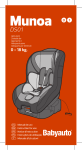
<Standard waveform>
Observation conditions
Point A
Point B
Injector
drive time
Solenoid counter emf
(approx. 7 × 10 V)
Power supply voltage
Probe selector switch
× 10
AC-GND-DC
DC
VOLTS/DIV.
1V
TIME/DIV.
Misc.
0.5 ms
–
Engine speed
Idle
<Explanation on waveform>
The power supply voltage is being normally applied and, when a signal is received from the engine
ECU, the voltage drops to around 0 V for the period of time equivalent to its drive signal.
When the signal from the engine ECU turns OFF, the counter emf of the coil causes a voltage peak
to develop, thus resuming the power supply voltage.
Injector drive time:
The fuel injection time as determined by the engine ECU according to the output values of sensors
including AFS. Injector drive time = effective injection time + invalid injection time (Invalid injection
time: corrects operation time lag caused by a power supply voltage drop)
Solenoid coil counter emf:
When the signal from the engine ECU turns OFF, counter emf occurs in the injector coil (approx.
65 to 75 V).
Power supply voltage:
The power supply voltage is being applied in the absence of a signal from the engine ECU. If this
voltage is low, it extends the invalid injection time and, thus, the drive time.
<Waveform observation points>
Point A: Strength of solenoid coil counter emf
Solenoid coil counter emf is low or zero.
Injector solenoid shorting
Point B: Injector drive time
When the engine is suddenly raced, the drive time temporarily
extends by a wide margin and soon returns to the normal
drive time corresponding to the engine speed.
At idle
During racing
13-28
MPI – Troubleshooting
Injector Power Supply Voltage (Oscilloscope 2)
<Measurement procedure>
(1) Disconnect the resistor connector and connect the special
tool (Harness Connector: MD998463) to the circuit.
(2) Connect the oscilloscope probe to resistor connector
terminal (1) (special tool red clip) when the waveform
is observed with no. 1 cylinder, to terminal (4) (black
clip) when the waveform is observed with no. 2 cylinder,
to terminal (5) (green clip) when the waveform is observed
with no. 3 cylinder, and to terminal (6) (yellow clip) when
the waveform is observed with no. 4 cylinder.
(3) For the power supply voltage, observe the waveform of
the injector control signal at the same time. (Refer to
P.13-26 for the injector control signal measurement
procedure.)
<Standard waveform>
Observation conditions
Injector power supply voltage waveform
Injector control signal
Probe selector switch
×1
× 10
AC-GND-DC
AC
DC
VOLTS/DIV.
5V
1V
TIME/DIV.
Misc.
0.5 ms
To be timed with injector control signal
Engine speed
Idle (850 rpm)
Plunger in fully
opened position
Point B
Injector power supply
voltage waveform
(oscilloscope 2)
Point A
Injector control signal
waveform
(oscilloscope 1)
Fuel injection time
Time
MPI – Troubleshooting
13-29
<Explanation of waveform>
The injector power supply voltage waveform shows a voltage drop caused by resistance of the resistor.
As the amount of current increases, voltage gradually decreases and a spike occurs at the plunger fully
opened position due to counter emf.
<Waveform observation points>
Point A: Voltage drop during fuel injection time (Refer to abnormal waveform example 1.)
Difference from standard waveform
Possible cause
Voltage drop during fuel injection time is small (there
should normally be a voltage drop of about 10 V).
Resistance of resistor is too small. Resistance of injector
is too large.
Point B: Spike when plunger is fully open (Refer to abnormal waveform example 2.)
Difference from standard waveform
Possible cause
No spike when plunger is fully open
Plunger inoperative
<Abnormal waveform examples>
D Example 1
[Cause of problem]
Resistance of the resistor is too small.
Abnormal waveform
[Waveform characteristics]
Small voltage drop
Normal waveform
D
Example 2
[Cause of problem]
Plunger is inoperative.
[Waveform characteristics]
No spike when plunger is fully open.
7-4 IGNITION COIL
Perform the same steps as with the conventional 4G9 engine
for the inspection.
13-30
MPI – On-vehicle Service
ON-VEHICLE SERVICE
1. IDLE POSITION SWITCH AND THROTTLE
POSITION SENSOR (TPS) ADJUSTMENT
The thickness of the feeler gauge inserted between the fixed
SAS and throttle lever should be 0.45 mm.
2. FIXED SAS ADJUSTMENT
<EVOLUTION-IV>
Turn down one turn after the fixed SAS has touched the
throttle lever.
<EVOLUTION-V>
Turn down 1-1/4 turns after the fixed SAS has touched the
throttle lever.
3. BASIC IDLE SPEED ADJUSTMENT
The basic idle speed should be 850 ± 50 rpm.
4. FUEL PRESSURE MEASUREMENT
The fuel pressure gauge should be installed at the location
shown on the left.
13-31
MPI – On-vehicle Service
5. MPI SYSTEM COMPONENTS LAYOUT
Name
Symbol
Name
Symbol
A/C switch
Q
Exhaust temperature warning lamp
S
A/C relay
H
Fuel pressure control valve
A
Air flow sensor (with a built-in intake air temperature
sensor and barometric pressure sensor)
F
Ignition coil and power transistor unit
L
Injector
B
Camshaft position sensor
M
ISC servo
D
Control relay and fuel pump relay
P
Oxygen sensor
K
Coolant temperature sensor
E
Power steering fluid pressure switch
I
Crank angle sensor
J
Secondary air control solenoid valve
N
Detonation sensor
C
Throttle position sensor (with a built-in idle switch)
D
Diagnosis connector
R
Engine ECU
O
Vehicle speed sensor
T
Engine warning lamp
S
Wastegate solenoid valve
G
13-32
MPI – On-vehicle Service
6. INTAKE AIR TEMPERATURE SENSOR
CHECK
Equipment sideconnector
1. Disconnect the air flow sensor connector.
2. Measure resistance between terminals 5 and 6.
Standard value:
2.3 – 3.0 kΩ (at 20_C)
0.30 – 0.42 kΩ (at 80_C)
Air flow sensor
Intake air temperature sensor
3. Measure resistance while heating the sensor using a hair
drier.
Normal condition:
Temperature (_C)
Resistance (kΩ)
Higher
Smaller
4. If the value deviates from the standard value or the
resistance remains unchanged, replace the air flow sensor
assembly.
7. ENGINE COOLANT TEMPERATURE
SENSOR CHECK
The engine coolant temperature sensor is located as shown
on the left.
Standard value:
2.1 – 2.7 kΩ (at 20_C)
0.26 – 0.36 kΩ (at 80_C)
Engine coolant
temperature sensor
Oxygen sensor equipment side connector
8. OXYGEN SENSOR CHECK
<EVOLUTION-IV>
The sensor connector is located as shown on the left.
Oxygen sensor connector
Oxygen sensor
<EVOLUTION-V>
(1) Disconnect the oxygen sensor connector and connect
the special tool (Test Harness: MD998464) to the oxygen
sensor connector.
13-33
MPI – On-vehicle Service
Red clip
(2) Check that there is continuity (11 to 18 Ω at 20_C) across
terminal no. 1 (special tool red clip) and terminal no. 3
(special tool blue clip) of the oxygen sensor connector.
(3) If there is no continuity, replace the oxygen sensor.
MD998464
Blue clip
(4) Run the engine until the engine coolant temperature
exceeds 80_C.
(5) Using jumper wires, connect oxygen sensor terminal no.
1 (special tool red clip) and terminal no. 3 (special tool
blue clip) to battery (+) and (–) terminal, respectively.
Red clip
Black clip
Blue clip
White clip
MD998464
Caution
Make sure of the correct connections: if a wrong
connection is made, a broken oxygen sensor results.
(6) Connect a digital voltmeter between terminal no. 2 (special
tool black clip) and terminal no. 4 (special tool white clip).
(7) Race the engine repeatedly to measure the oxygen sensor
output voltage.
Standard value:
Engine
Oxygen sensor
output voltage
NOTE
When
engine is
raced
0.6 – 1.0 V
When engine racing is
repeated to enrich air-fuel
ratio, an operational oxygen
sensor should output a voltage of 0.6 to 1.0 V.
NOTE
Use the same procedures to remove and install the oxygen
sensor.
13-34
MPI – On-vehicle Service
9. INJECTOR CHECK
Injection Condition Check
(1) Release the residual pressure from the fuel pipe line to
prevent fuel from flowing out.
(2) Remove the injector.
(3) Set up the special tools (Injector Test Set, Adapter, Fuel
Pressure Regulator, and Clip) as illustrated below.
(4) From here on, use the same procedure as with the
conventional 4G9 engine for the check.
Main hose
MD998741
Return hose
MB991607
Fuel Pressure Regulator: MD116395
MD998706
Clip: MD998746
Battery
Injector
10. RESISTOR CHECK
Resistor
(1) Disconnect the resistor connector.
(2) Measure resistance across terminals as detailed below.
Standard value
Measurement terminals
Resistance (Ω)
1–3
4–3
5.5
5 5 to 6.5
6 5 (at 20_C)
5–3
6–3
13-35
MPI – On-vehicle Service
11. FUEL PUMP RELAY NO.2 CHECK
(1) Remove fuel pump relay No.2.
Fuel pump relay No.2
(2) Using jumper wires, connect fuel pump relay No.2 terminal
(3) to battery (+) terminal, and terminal (1) to battery
(–) terminal, respectively.
(3) Connecting and disconnecting the jumper wire on the
battery (–) terminal end, check for continuity across
terminal (2) and terminal (5), and across terminal (4) and
terminal (5), of fuel pump relay No.2.
Jumper wire
Continuity across
terminals (2) and (5)
Continuity across
terminals (4) and (5)
Connected
No
Yes
Disconnected
Yes
No
(4) If the continuity is checked abnormally, replace fuel pump
relay No.2.
12. FUEL PUMP RESISTOR CHECK
(1) Disconnect the fuel pump resistor connector.
Fuel pump resistor
(2) Measure resistance across the terminals.
Standard value: 0.6 – 0.9 Ω
(3) If the measurement falls outside the specified range,
replace the fuel pump resistor.
13-36
MPI – Injector
INJECTOR
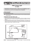
REMOVAL AND INSTALLATION
Pre-removal Operation
(1) Fuel Discharge Prevention
(2) Air Hose D Removal
(Refer to GROUP15 – Intercooler.)
Post-installation Operation
(1) Air Hose D Installation
(Refer to GROUP15 – Intercooler.)
(2) Fuel Leakage Check
3, 6
9
3
8
O-ring
1
8
4
11
5
12
11
10
7
10 – 13 {1.0 – 1.3}
6
4
12
O-ring
Engine oil
9 {0.9}
2
Unit: Nm {kgf@m}
AA"
AA"
Removal steps
1. Injector connector
2. PCV hose connection
3. High-pressure fuel hose connection
4. Fuel return hose connection
5. Vacuum hose connector
6. Fuel pressure regulator
7.
8.
9.
10.
AA" "AA 11.
12.
AA"
Fuel return pipe
Delivery pipe
Insulator
Insulator
Injector
Grommet
13-37
MPI – Throttle Body
THROTTLE BODY
REMOVAL AND INSTALLATION
Pre-removal Operation
(1) Engine Coolant Draining
(2) Air Hose D Removal
(Refer to GROUP 15 – Intercooler.)
(3) Strut Tower Bar Removal
Post-installation Operation
(1) Strut Tower Bar Installation
(2) Air Hose D Installation
(Refer to GROUP 15 – Intercooler.)
(3) Engine Coolant Supplying
(4) Accelerator Cable Adjustment
5 {0.5}
2
4
19 {1.9}
1
7
3
6
5
Unit: Nm {kgf@m}
Removal steps
1. Accelerator cable connection
2. Throttle position sensor connector
3. Idle speed control servo connector
4. Vacuum hose connection
Up
5. Water hose connection
6. Throttle body
"AA 7. Throttle body gasket
INSTALLATION SERVICE POINT
"AA THROTTLE BODY GASKET INSTALLATION
Place the gasket so that the projecting part is positioned
as shown in the illustration, and then install it between the
intake manifold and the throttle body.
Towards front
of vehicle