1
00-1
GROUP 00
GENERAL
CONTENTS
HOW TO USE THIS MANUAL. . . . . .
00-3
HOW TO PERFORM VEHICLE IDENTIFICATION
NUMBER (VIN) WRITING . . . . . . . . . . . . . .
00-22
TROUBLESHOOTING GUIDELINES
00-6
CODING LIST . . . . . . . . . . . . . . . . . . . . . . .
00-26
INITIALIZATION PROCEDURE FOR
LEARNING VALUE IN MFI ENGINE . . . . . .
00-35
ENGINE IDLING LEARNING
PROCEDURE . . . . . . . . . . . . . . . . . . . . . . .
00-36
TIMING CHAIN MAINTENANCE. . . . . . . . .
00-37
SERVICING ELECTRICAL SYSTEM . . . . .
00-41
HOW TO USE
TROUBLESHOOTING/INSPECTION
SERVICE POINTS . . . . . . . . . . . . . . .
00-7
TROUBLESHOOTING CONTENTS . . . . . .
00-7
HOW TO USE THE INSPECTION
PROCEDURES. . . . . . . . . . . . . . . . . . . . . .
00-10
CONNECTOR MEASUREMENT SERVICE
POINTS. . . . . . . . . . . . . . . . . . . . . . . . . . . .
HOW TO SHIFT LOCK FORCED
RELEASE . . . . . . . . . . . . . . . . . . . . . . . . . .
00-42
00-12
VEHICLE WASHING . . . . . . . . . . . . . . . . . .
00-43
CONNECTOR INSPECTION SERVICE
POINTS. . . . . . . . . . . . . . . . . . . . . . . . . . . .
00-14
APPLICATION OF ANTI-CORROSION
AGENTS AND UNDERCOATS . . . . . . . . . .
00-43
HOW TO COPE WITH INTERMITTENT
MALFUNCTIONS . . . . . . . . . . . . . . . . . . . .
00-15
BOLTS AND NUTS WITH STABILIZER FOR
COEFFICIENT OF FRICTION. . . . . . . . . . .
00-43
HOW TO TREAT PAST TROUBLE . . . . . .
00-16
FORM−IN−PLACE GASKET (FIPG) . . . . . . .
00-43
INSPECTION SERVICE POINTS FOR
A BLOWN FUSE . . . . . . . . . . . . . . . . . . . . .
00-17
TOWING AND HOISTING. . . . . . . . . .
00-45
00-17
GENERAL DATA AND
SPECIFICATIONS . . . . . . . . . . . . . . .
00-49
TIGHTENING TORQUE . . . . . . . . . . .
00-51
LUBRICATION AND
MAINTENANCE . . . . . . . . . . . . . . . . .
00-52
RECOMMENDED LUBRICANTS AND
LUBRICANT CAPACITIES TABLE . .
00-54
SCHEDULED MAINTENANCE
TABLE. . . . . . . . . . . . . . . . . . . . . . . . .
00-57
VEHICLE IDENTIFICATION . . . . . . .
VEHICLE IDENTIFICATION NUMBER
PLATE. . . . . . . . . . . . . . . . . . . . . . . . . . . . .
00-17
MODELS . . . . . . . . . . . . . . . . . . . . . . . . . . .
00-18
CHASSIS NUMBER . . . . . . . . . . . . . . . . . .
00-19
ENGINE MODEL STAMPING. . . . . . . . . . .
00-19
VEHICLE IDENTIFICATION CODE PLATE
00-19
TIRE AND LOADING INFORMATION
PLACARD . . . . . . . . . . . . . . . . . . . . . . . . . .
00-20
PRECAUTIONS BEFORE SERVICE.
00-20
CAUTIONS FOR WORKING IN ENGINE
COMPARTMENT . . . . . . . . . . . . . . . . . . . .
00-20
SUPPLEMENTAL RESTRAINT SYSTEM
(SRS) . . . . . . . . . . . . . . . . . . . . . . . . . . . . .
00-20
SCAN TOOL (MULTI USE TESTER
{ M.U.T.-III } SUB ASSEMBLY). . . . . . . . . .
00-21
Continued on next page
00-2
MAINTENANCE SERVICE . . . . . . . .
00-61
1. FUEL SYSTEM (TANK, PIPE LINE AND
CONNECTION, AND FUEL TANK FILLER
TUBE CAP) (CHECK FOR LEAKS) . . . . . .
00-61
2. FUEL HOSES (CHECK CONDITION) . .
00-61
3. AIR CLEANER ELEMENT (REPLACE) .
00-61
4. EVAPORATIVE EMISSION CONTROL
SYSTEM (EXCEPT EVAPORATIVE EMISSION
CANISTER) (CHECK FOR LEAKS AND
CLOGGING) . . . . . . . . . . . . . . . . . . . . . . . .
00-61
5. SPARK PLUGS (REPLACE). . . . . . . . . .
00-62
6. INTAKE AND EXHAUST VALVE CLEARANCE
(INSPECT AND ADJUST). . . . . . . . . . . . . .
00-62
7. DRIVE BELT (FOR THE GENERATOR AND
POWER STEERING OIL PUMP)
(REPLACE) . . . . . . . . . . . . . . . . . . . . . . . . .
00-64
8. EXHAUST SYSTEM (CONNECTIONS
PORTION OF MUFFLER, MUFFLER PIPES AND
CONVERTER HEAT SHIELDS) (CHECK AND
SERVICE) . . . . . . . . . . . . . . . . . . . . . . . . . .
00-65
9. ENGINE OIL (CHANGE). . . . . . . . . . . . .
00-65
10. ENGINE OIL FILTER (REPLACE) . . . .
00-66
11. MANUAL TRANSAXLE OIL (CHECK OIL
LEVEL AND CONDITION/RCHANGE) . . . .
00-66
12. TWIN CLUTCH-SPORTRONIC SHIFT
TRANSMISSION (TC-SST) [CHECK THE
FLUID LEAKAGE (IF NECESSARY, CHECK
THE FLUID LEVEL) /CHANGE] . . . . . . . . .
00-68
13. TWIN CLUTCH SPORT-SHIFT
TRANSMISSION OIL FILTER (CHANGE) .
00-70
14. TRANSFER OIL (CHECK OIL LEVEL/
CHANGE) . . . . . . . . . . . . . . . . . . . . . . . . . .
00-70
15. RESERVE TANK FLUID (FOR ACTIVE
CENTER DIFFERENTIAL AND ACTIVE YAW
CONTROL SYSTEM) (CHECK FLUID
LEVEL) . . . . . . . . . . . . . . . . . . . . . . . . . . . .
00-71
16. ENGINE COOLANT (CHANGE) . . . . . .
00-72
17. COOLANT HOSES (RADIATOR HOSE,
HEATER HOSE) (INSPECT). . . . . . . . . . . .
00-74
18. DISK BRAKE PADS AND ROTORS
(INSPECT FOR WEAR) . . . . . . . . . . . . . . .
00-74
19. BRAKE HOSES (CHECK FOR
DETERIORATION OR LEAKS) . . . . . . . . . .
00-77
20. BALL JOINT AND STEERING LINKAGE
SEALS (INSPECT FOR GREASE LEAKS AND
DAMAGE) . . . . . . . . . . . . . . . . . . . . . . . . . .
00-78
21. DRIVE SHAFT BOOTS (INSPECT FOR
GREASE LEAKS AND DAMAGE). . . . . . . .
00-78
22. SUSPENSION SYSTEM (INSPECT FOR
LOOSENESS AND DAMAGE) . . . . . . . . . .
00-78
23. REAR AXLE OIL (FOR DIFFERENTIAL
PART) (CHANGE) . . . . . . . . . . . . . . . . . . . .
00-78
24. REAR AXLE OIL (FOR TORQUE
TRANSFER MECHANISM PART)
(CHANGE) . . . . . . . . . . . . . . . . . . . . . . . . . .
00-79
25. TIRES (ROTATE) . . . . . . . . . . . . . . . . .
00-79
26. AIR PURIFIER FILTER (REPLACE) . . .
00-79
MAIN SEALANT AND ADHESIVE
TABLE. . . . . . . . . . . . . . . . . . . . . . . . .
00-80
00-3
GENERAL
HOW TO USE THIS MANUAL
HOW TO USE THIS MANUAL
MAINTENANCE, REPAIR AND
SERVICING EXPLANATIONS
This manual provides explanations, etc. concerning
procedures for the inspection, maintenance, repair
and servicing of the subject model. Unless otherwise
specified, each service procedure covers all models.
Procedures covering specific models are identified
by the model codes, or similar designation (engine
type, transaxle type, etc.). A description of these designations is covered in this manual under "VEHICLE
IDENTIFICATION."
.
ON-VEHICLE SERVICE
The "ON-VEHICLE SERVICE" section has procedures for performing inspections and adjustments of
particularly important components. These procedures are done with regard to maintenance and servicing, but other inspections (looseness, play,
cracking, damage, etc.) must also be performed.
M1001000102547
DANGER, WARNING, AND CAUTION
DANGER, WARNING, and CAUTION call special
attention to a necessary action or to an action that
must be avoided. The differences among DANGER,
WARNING, and CAUTION are as follows:
• If a DANGER is not followed, the result is severe
bodily harm or even death.
• If a WARNING is not followed, the result could be
bodily injury.
• If a CAUTION is not followed, the result could be
damage to the vehicle, vehicle components or
service equipment.
TIGHTENING TORQUE INDICATION
The tightening torque indicates a median and its tolerance by a unit of N⋅ m (in-lb) or N⋅ m (ft-lb). For
fasteners with no assigned torque value, refer to
P.00-51.
SPECIAL TOOL NOTE
.
SERVICE PROCEDURES
The service steps are arranged in numerical order.
Attention to be paid in performing vehicle service are
described in detail in SERVICE POINTS.
DEFINITION OF TERMS
Only MMC special tool part numbers are called out in
the repair sections of this manual. Please refer to the
special tool cross-reference chart located at the
beginning of each group, for the special tool number
that is available in your market.
ABBREVIATIONS
.
STANDARD VALUE
Indicates the value used as the standard for judging
whether or not a part or adjustment is correct.
.
LIMIT
Shows the maximum or minimum value for judging
whether or not a part or adjustment is acceptable.
.
REFERENCE VALUE
Indicates the adjustment value prior to starting the
work (presented in order to facilitate assembly and
adjustment procedures, and so they can be completed in a shorter time).
.
TSB Revision
The following abbreviations are used in this manual
for classification of model types:
2.0 L engine:1.998 liter <4B11> engine, or a model
equipped with such an engine.
A/C: Air conditioning.
AWD: Indicates the all wheel drive vehicles.
Keyless Operation System (KOS):Free-hand
Advanced Security Transmitter (F.A.S.T.-key)
M/T:Indicates manual transaxle, or models equipped
with manual transaxle.
MFI: Multiport fuel injection, or engines equipped
with multiport fuel injection.
ECM: Indicates the engine control module
TCM: Indicates the transaxle control module
TC-SST:Indicates the twin clutch-sportronic shift
transmission.
00-4
GENERAL
HOW TO USE THIS MANUAL
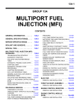
EXPLANATION OF MANUAL CONTENTS
Denotes tightening torque.
For bolts and nuts which do
not have a tightening torque
listed, refer to the "Standard
Parts tightening-torque Table"
Indicates the
section title.
Indicates the
group title.
Indicates the
group number.
Indicates the page number.
Indicates procedures to be performed before the work in that section is started, and
procedures to be performed after the work
in that section is finished.
Component diagram
A diagram of the component parts is provided near the front of each section in order
to give the reader a better understanding of
the installed condition of component parts.
Mark N denotes nonreusable part.
Repair kit or parts sets are shown.
(Only very frequently used parts are shown.)
>>A<<
>>B<<
Maintenance and servicing procedures
The numbers provided within the diagram indicate the
sequence for maintenance and servicing procedures.
Removal steps :
The part designation number corresponds to
the number in the illustration to indicate removal steps.
Disassembly steps :
The part designation number corresponds to
the number in the illustration to indicate disassembly steps.
Installation steps :
Specified in case installation is impossible in
reverse order of removal steps. Omitted if
installation is possible in reverse order of removal steps.
Reassembly steps :
Specified in case installation is impossible in
reverse order of removal steps. Omitted if
reassembly is possible in reverse order of disassembly steps.
AC901523
TSB Revision
00-5
GENERAL
HOW TO USE THIS MANUAL
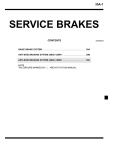
Classifications of major maintenance / service points
When there are major points relative to maintenance and servicing procedures (such as essential maintenance
and service points, maintenance and service standard values, information regarding the use of special tools, etc.).
These are arranged together as major maintenance and service points and explained in detail.
<<A>> : Indicates that there are essential points for removal or disassembly.
>>A<< : Indicates that there are essential points for installation or reassembly.
35A-21
Operating procedures,
cautions, etc. on removal,
installation, disassembly and
reassembly are described
BRAKE CALIPER ASSEMBLY
The title of the page
(following the page on which
the diagram of component
parts is presented) indicating
the locations of lubrication and
sealing procedures.
Indicates (by symbols) where
lubrication is necessary.
Symbols for lubrication, sealants and adhesives
Symbols are used to show the locations for lubrication
and for application of sealants and adhesives.
These symbols are included in the diagram of component parts or on the page following the component
parts page. The symbols do not always have accompanying text to support that symbol.
: Grease
(Multi-purpose grease unless there is a brand
or type specified)
: Sealant or adhesive
: Automatic transmission fluid, brake fluid, power
steering fluid or air conditioning compressor oil
: Engine oil or gear oil
: Adhesive tape or butyl rubber tape
AC509265AO
TSB Revision
00-6
GENERAL
TROUBLESHOOTING GUIDELINES
TROUBLESHOOTING GUIDELINES
VERIFY THE COMPLAINT
M1001008800287
FIND THE PROBLEM
• Make sure the customer's complaint and the service writer's work order description are understood before starting work.
• Make sure the correct operation of the system is
understood. Read the service manual description
to verify normal system operation.
• Operate the system to see the symptoms. Look
for other symptoms that were not reported by the
customer, or on the work order, that may be
related to the problem.
DETERMINE POSSIBLE CAUSES
Compare the confirmed symptoms to the diagnostic
symptom indexes to find the right diagnosis procedure.
If the confirmed symptoms cannot be found on any
symptom index, determine other possible causes.
• Analyze the system diagrams and list all possible
causes for the problem symptoms.
• Rank all these possible causes in order of probability, based on how much of the system they
cover, how likely they are to be the cause, and
how easy they will be to check. Be sure to take
experience into account. Consider the causes of
similar problems seen in the past. The list of
causes should be ranked in order from general to
specific, from most-likely to least-likely, and from
easy-to-check to hard-to-check.
TSB Revision
After the symptoms have been confirmed, and probable causes have been identified, the next step is to
make step-by-step checks of the suspected system
components, junctions, and links in logical order.
Use the diagnostic procedures in the service manual
whenever possible. Follow these procedures carefully to avoid missing an important step in the diagnosis sequence. It might be the skipped step that leads
to the solution of the problem.
If the service manual doesn't have step-by-step procedures to help diagnose the problem, make a series
of checks based on the ranked list of probable
causes. Troubleshooting checks should be made in
the order that the list of causes was ranked:
• general to specific
• most-likely to least-likely
• easy-to-check to hard-to-check
REPAIR THE PROBLEM
When the step-by-step troubleshooting checks find a
fault, perform the proper repairs. Make sure to fix the
root cause of the problem, not just the symptom. Just
fixing the symptom, without fixing the root cause, will
cause the symptom to eventually return.
VERIFY THE REPAIR
After repairs are made, recheck the operation of the
system to confirm that the problem is eliminated. Be
sure to check the system thoroughly. Sometimes
new problems are revealed after repairs have been
made.
00-7
GENERAL
HOW TO USE TROUBLESHOOTING/INSPECTION SERVICE POINTS
HOW TO USE TROUBLESHOOTING/INSPECTION
SERVICE POINTS
TROUBLESHOOTING CONTENTS
DANGER
The SRS-ECU adopts the rollover specification that the curtain air bag and seat belt
pre-tensioner operate at the occurrence of
rollover. Therefore, do not tilt the vehicle to
the right and left with the IG ON or tilt the
SRS-ECU to the right and left with the IG ON
and the harness installed.
CAUTION
During diagnosis, a diagnostic trouble code
associated with other system may be set when
the ignition switch is turned "ON" with connector(s) disconnected. On completion, confirm all
systems for diagnostic trouble code(s). If diagnostic trouble code(s) are set, erase them all.
WARNING
Since the radiator fan rotates during CAN
bus line diagnostics, make sure that no one
is servicing the engine compartment before
diagnosing the CAN bus line. Since the CAN
communication stops when diagnosing the
CAN bus line, the ETACS-ECU detects the
time-out of the engine control module, and
activates the radiator fan to prevent overheating as fail-safe.
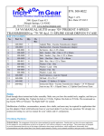
1. STANDARD FLOW OF DIAGNOSTIC TROUBLESHOOTING
Troubleshooting sections are based on the diagnostic flow as below. If the diagnostic flow is different
from that given below, or if additional explanation is
required, the details of such differences or additions
will also be listed.
TSB Revision
M1001013300653
Troubleshooting of electronic control systems for
which scan tool MB991958 can be used follows the
basic outline described below. Even in systems for
which scan tool MB991958 cannot be used, some of
these systems still follow this outline.
00-8
GENERAL
HOW TO USE TROUBLESHOOTING/INSPECTION SERVICE POINTS
Diagnostic method
Gathering information
from the customer
Coding data check* 6
Reoccurs
Does not reoccur
Check trouble symptom
CAN bus diagnosis.*1
NG
CAN bus diagnosis chart *2
OK
Read the diagnosis code.
No diagnosis
code or
communication
with scan tool
MB991958 not
possible.
diagnosis code
displayed.
Read the diagnosis code.
(Current trouble)*3
diagnosis code
displayed.
(Current trouble)*3
After taking note of the
malfunction code, erase the
diagnosis cod memory.
diagnosis code
displayed.
(Current trouble)*3
How to treat past
trouble.*4
Recheck trouble symptom.
Read the diagnosis code.
diagnosis code
displayed.
(Current trouble)*3
No diagnosis
code.
How to treat past
trouble*4
No diagnosis
code.
diagnosis code
displayed.
Refer to the INSPECTION CHART
FOR TROUBLE SYMPTOMS
(Refer to applicable group).
Refer to the INSPECTION CHART
FOR DIAGNOSIS CODES
(Refer to applicable group).
INTERMITTENT MALFUNCTIONS* 5
AC704160
1
• * : For how to diagnose CAN bus lines, refer to
GROUP 54C P.54C-9.
• *2: For the CAN bus diagnosis chart, refer to
GROUP 54C P.54C-15.
• *3: When scan tool MB991958 detects a diagnostic trouble code, its display informs users whether
a mechanical problem currently exists or whether
it existed before. The message for the former
state identifies it as an "Active" and the message
for the latter identifies it as a "Stored".
• *4: For how to treat past trouble, refer to P.00-16.
• *5: For how to cope with intermittent malfunctions, refer to P.00-15.
• *6: For coding data, refer to P.00-26.
2. SYSTEM OPERATION AND SYMPTOM
VERIFICATION TESTS
If verification of the symptom(s) is difficult, procedures for checking operation and verifying symptoms
are shown.
TSB Revision
3. DIAGNOSTIC FUNCTION
The following trouble code diagnosis are shown.
• How to read diagnostic trouble codes
• How to erase diagnostic trouble codes
• Input inspection service points
4. DIAGNOSTIC TROUBLE CODE CHART
If the scan tool displays a diagnostic trouble code,
find the applicable inspection procedure according to
this chart.
5. SYMPTOM CHART
If there are symptoms, even though the scan tools
show that no DTCs are set, inspection procedures
for each symptom will be found by using this chart.
6. DIAGNOSTIC TROUBLE CODE
PROCEDURES
Indicates the inspection procedures corresponding to
each diagnostic trouble code. (Refer to P.00-10).
GENERAL
HOW TO USE TROUBLESHOOTING/INSPECTION SERVICE POINTS
7. SYMPTOM PROCEDURES
Indicates the inspection procedures corresponding to
each symptom listed in the Symptom Chart. (Refer to
P.00-10).
8. SERVICE DATA REFERENCE TABLE
Inspection items and normal judgment values have
been provided in this chart as reference information.
9. CHECK AT ECU TERMINALS
Terminal numbers for the ECU connectors, inspection items, and standard values have been provided
in this chart as reference information.
.
TERMINAL VOLTAGE CHECKS
1. Connect a needle-nosed wire probe to a voltmeter
probe.
CAUTION
Short-circuiting the positive (+) probe between a
connector terminal and ground could damage
the vehicle wiring, the sensor, the ECU, or all
three. Use care to prevent this!
2. Insert the needle-nosed wire probe into each of
the ECU connector terminals from the wire side,
and measure the voltage while referring to the
check chart.
NOTE: Measure voltage with the ECU connectors
connected.
You may find it convenient to pull out the ECU to
make it easier to reach the connector terminals.
Checks don't have to be carried out in the order
given in the chart.
3. If voltage readings differ from normal condition
values, check related sensors, actuators, and
wiring. Replace or repair as needed.
TSB Revision
00-9
4. After repair or replacement, recheck with the
voltmeter to confirm that the repair has corrected
the problem.
.
TERMINAL RESISTANCE AND
CONTINUITY CHECKS
1. Turn the ignition switch to the "LOCK" (OFF)
position.
2. Disconnect the ECU connector.
CAUTION
If resistance and continuity checks are performed on the wrong terminals, damage to the
vehicle wiring, sensors, ECU, and/or ohmmeter
may occur. Use care to prevent this!
3. Measure the resistance and check for continuity
between the terminals of the ECU harness-side
connector while referring to the check chart.
NOTE: Checks don't have to be carried out in the
order given in the chart.
4. If the ohmmeter shows any deviation from the
Normal Condition value, check the corresponding
sensor, actuator and related electrical wiring, then
repair or replace.
5. After repair or replacement, recheck with the
ohmmeter to confirm that the repair has corrected
the problem.
10. INSPECTION PROCEDURES USING
AN OSCILLOSCOPE
When there are inspection procedures using an
oscilloscope, these are listed.
00-10
GENERAL
HOW TO USE TROUBLESHOOTING/INSPECTION SERVICE POINTS
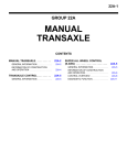
HOW TO USE THE INSPECTION PROCEDURES
M1001013500550
The causes of many of the problems occurring in electric circuitry are generally the connectors, components,
the ECU, and the harnesses between connectors, in that order. These inspection procedures follow this
order. They first try to discover a problem with a connector or a defective component.
Air temperature
Temperaturecircuit
Circuitmalfunction
Malfunction
Intake air
Intake air temperature sensor
(Incorporated in volume air
flow sensor)
(1) Relevant circuit(s) of the component which
the DTC indicates are described.
Powertrain
control
module (PCM)
(2) For connector color, refer to GROUP 80A,
How to read configuration diagrams.
Connector: B-48
Intake air
temperature
sensor
(3) Shows the location of the connector(s) from
the circuit(s) above.
(4) Explains about the operation principle of the
component or its relevant parts in that circuit.
B-48(B)
AC610770AB
TSB Revision
00-11
GENERAL
HOW TO USE TROUBLESHOOTING/INSPECTION SERVICE POINTS
(5) Explains about technical details.
(6) Describes the conditions for that DTC
being set (stored).
(7) Describes possible
cause(s)for that DTC.
(8) Start of the diagnosis procedure
for that DTC.
Required special tool:
(9) Identifies the special tool(s)
necessary for diagnosing that DTC.
Data link
connector
(10) Provides the inspection procedure
for that DTC step by step.
AC210616 AD
HARNESS INSPECTION
Check for an open or short circuit in the harness
between the terminals which were faulty according to
the connector measurements. Carry out this inspection while referring to GROUP 00E, Harness Connector Inspection P.00E-2. Here, "Check harness
between power supply and terminal xx" also includes
checking for blown fuse. For inspection service
points when there is a blown fuse, refer to "Inspection Service Points for a Blown Fuse P.00-17."
TSB Revision
MEASURES TO TAKE AFTER
REPLACING THE ECU
If the trouble symptoms have not disappeared even
after replacing the ECU, repeat the inspection procedure from the beginning.
00-12
GENERAL
HOW TO USE TROUBLESHOOTING/INSPECTION SERVICE POINTS
CONNECTOR MEASUREMENT SERVICE POINTS
M1001013600610
Turn the ignition switch to the "LOCK" (OFF) position when
connecting and disconnecting the connectors. Turn the ignition
switch to "ON" when measuring, unless there are instructions
to the contrary.
IF INSPECTING WITH THE CONNECTOR
CONNECTED <WATERPROOF CONNECTORS>
SpecialTOOL
tool
SPECIAL
Be sure to use special tool. Never insert a test probe from the
harness side, as this will reduce the waterproof performance
and result in corrosion.
ACX00863AF
IF INSPECTING WITH THE CONNECTOR
CONNECTED <ORDINARY (NON-WATERPROOF)
CONNECTORS>
Required Special Tool:
• MB992006: Extra Fine Probe
Inspect by inserting a test probe from the harness side. If the
connector is too small to insert a test probe (e.g. control unit
connector), do not insert it forcibly. Use special tool MB992006
(extra fine probe).
MB992006
AC105598AG
IF INSPECTING WITH THE CONNECTOR
DISCONNECTED
<When Inspecting a Female Pin>
• From front side of the connector
Required Special Tool:
MB991219: Inspection Harness (Included in MB991223,
Harness Set)
TSB Revision
GENERAL
HOW TO USE TROUBLESHOOTING/INSPECTION SERVICE POINTS
00-13
The inspection harness for connector pin contact pressure should be used. The test probe should never be
forcibly inserted, as it may cause a defective contact.
MB991219
ACX00865 AB
• From back side of the connector (SRS-ECU harness side
connector)
Since the SRS-ECU harness connector is plated to improve
conductivity, observe the warning below when checking
this connector.
SRS-ECU
harness connector
WARNING
AC001607AC
Insert the backprobing tool into the connector from
the harness side, and connect the tester to the backprobing tool. If any tool other than the backprobing
tool is used, it may cause damage to the harness and
other components. Furthermore, measurement
should not be carried out by touching the backprobing tool directly against the terminals from the front
of the connector. The terminals are plated to increase
their conductivity, so that if they are touched directly
by the backprobing tool, the plating may break, which
will decrease reliability.
<When Inspecting a Male Pin>
CAUTION
At this time, be careful not to short the connector pins with
the test probes. Doing so may damage the circuits inside
the ECU.
Touch the pin directly with the test probe.
ACX00867 AB
TSB Revision
00-14
GENERAL
HOW TO USE TROUBLESHOOTING/INSPECTION SERVICE POINTS
CONNECTOR INSPECTION SERVICE POINTS
M1001013700424
VISUAL INSPECTION
•
•
•
•
•
Connector disconnected or
improperly connected
Connector is disconnected or improperly connected
Connector pins are pulled out
Stretched an broken wires at terminal section
Low contact pressure between male and female terminals
Low connection pressure due to rusted terminals or foreign
matter lodged in terminals
Stretched or broken wires
Harness wire breakage
at terminal section
Low contact
pressure
Good
Bad
ACX00868AE
.
CONNECTOR PIN INSPECTION
If the connector pin stopper is damaged, the terminal connections (male and female pins) will not be perfect even when the
connector body is connected, because the pins may pull out of
the back side of the connector. Therefore, gently pull the wires
one by one to make sure that no pins pull out of the connector.
ACX00869AB
.
TSB Revision
GENERAL
HOW TO USE TROUBLESHOOTING/INSPECTION SERVICE POINTS
00-15
CONNECTOR ENGAGEMENT INSPECTION
MB991219
Required Special Tool:
MB991219: Inspection Harness (contained in MB991223 Test
Harness)
Use special tool, MB991219 to inspect the engagement of the
male pins and female pins. [Pin drawing force: 1 N (0.2 pound)
or more]
ACX00870 AB
HOW TO COPE WITH INTERMITTENT
MALFUNCTIONS
M1001013900451
Most intermittent malfunctions occur under certain conditions. If
those conditions can be identified, the cause will be easier to
find.
.
TO COPE WITH INTERMITTENT MALFUNCTION;
1. ASK THE CUSTOMER ABOUT THE
MALFUNCTION
Ask what it feels like, what it sounds like, etc. Then ask about
driving conditions, weather, frequency of occurrence, and so
on.
.
2. DETERMINE THE CONDITIONS FROM THE
CUSTOMER'S RESPONSES
Typically, almost all intermittent malfunctions occur from conditions like vibration, temperature and/or moisture change, poor
connections. From the customer's responses, it should be reasoned which condition is most likely.
.
3. USE SIMULATION TEST
Use the simulation tests below to attempt to duplicate the customer's complaint. Determine the most likely circuit(s) and perform the simulation tests on the connectors and parts of that
circuit(s). Be sure to use the inspection procedures provided for
diagnostic trouble codes and trouble symptoms.
For temperature and/or moisture condition related intermittent
malfunctions, try to change the conditions of the suspected circuit components, then use the simulation tests below.
.
TSB Revision
00-16
GENERAL
HOW TO USE TROUBLESHOOTING/INSPECTION SERVICE POINTS
4. VERIFY THE INTERMITTENT MALFUNCTION IS
ELIMINATED
Repair the malfunctioning part and try to duplicate the condition(s) again to verify the intermittent malfunction has been
eliminated.
.
SIMULATION TESTS
NOTE: In case of difficulty in finding the cause of the intermittent malfunction, the data recorder function in the scan tool is
effective.
For these simulation tests, shake, then gently bend, pull, and
twist the wiring of each of these examples to duplicate the intermittent malfunction.
• Shake the connector up-and-down, and right-and-left.
• Shake the wiring harness up-and-down, and right-and-left.
Especially, check the splice points of wiring harnesses carefully. Refer to GROUP 00E, Harness Connector Inspection
P.00E-2.
• Shake the part or sensor.
ACX00871 AB
HOW TO TREAT PAST TROUBLE
Since the trouble may still be present even the status
is "Stored", set the vehicle to the diagnostic trouble
code detection condition and check that the status
changes to "Active". If the status does not change
from "Stored", carry out the following procedure.
1. Establish from the customer whether a fuse or
connector has been replaced or disconnected.
TSB Revision
M1001014100384
2. If yes, erase the diagnostic trouble code, and then
check that no diagnostic code is reset. If no
diagnostic trouble code is reset, the diagnosis is
complete.
3. If no, follow the applicable Diagnostic Trouble
Code Chart. Then check the wiring harness and
connector, and refer to "How to Cope with
Intermittent Malfunction P.00-15 ."
00-17
GENERAL
VEHICLE IDENTIFICATION
INSPECTION SERVICE POINTS FOR A BLOWN
FUSE
M1001013800409
Remove the blown fuse and measure the resistance between
the load side of the blown fuse and the ground. Close the
switches of all circuits which are connected to this fuse. If the
resistance is almost 0 Ω at this time, there is a short somewhere between these switches and the load. If the resistance is
not 0 Ω, there is no short at the present time, but a momentary
short has probably caused the fuse to blow.
The main causes of a short circuit are the following.
• Harness being clamped by the vehicle body
• Damage to the outer casing of the harness due to wear or
heat
• Water getting into the connector or circuitry
• Human error (mistakenly shorting a circuit, etc.)
Battery
Fuse
Load
switch
Shortcircuit
occurrence
section
Load
ACX00872 AD
VEHICLE IDENTIFICATION
VEHICLE IDENTIFICATION NUMBER PLATE
M1001005501138
The vehicle identification number (VIN) plate is located on a
plate attached to the left top side of the instrument panel.
AC205735
CODE CHART
No. Item
2W8 F
J A 3A
6V_A
8U000001
12
1
Country
J
JAPAN
2
Make
A
Mitsubishi Motors
3
Vehicle type
3
Passenger car
4
Others
2
Air bags (driver, passenger, side
curtain, driver knee)
5
Line
W LANCER EVOLUTION
1 2 3 4 5 6 7 8 9 10 11
AC707964AC
Content
TSB Revision
00-18
GENERAL
VEHICLE IDENTIFICATION
No.
Item
Content
6
Trim level
(Price class)
5
PREMIUM
8
SPORTS
7
Body style
F
4-door sedan
8
Engine type
V
2.0L DOHC MIVEC with charge
air cooler, turbocharger (4B11)
9
Check digits*
0, 1, 2, 3, -----------9, X
10
Model year
A
11
Plant
U Mizushima
12
Serial number
000001 to 999999
2010 year
NOTE: *: Check digit means a single number, or letter X, used
to verify the accuracy of transcription of vehicle identification
number.
MODELS
M1001000304503
VEHICLE IDENTIFICATION NUMBER LIST
.
VEHICLES FOR USA
(VEHICLES FOR 50 STATES)
VIN (Except
Model code
serial number)
JA32W8FV_AU
CZ4AS
JA32W8FV_AU
JA32W5FV_AU
Engine model
NGFZL2M
4B11 [1,998 cm3 (121.9 cu in)
MGFZL2M DOHC MIVEC gasoline
MPFZL2M engine with charge air cooler
turbocharger]
(VEHICLES FOR PUERTO RICO)
VIN (Except
Model code
serial number)
JA32W8FV_AU
CZ4AS
JA32W8FV_AU
JA32W5FV_AU
Engine model
NGFZL2M
4B11 [1,998 cm3 (121.9 cu in)
MGFZL2M DOHC MIVEC gasoline
MPFZL2M engine with charge air cooler
turbocharger]
Transaxle model
Fuel
system
W5M6A (AWD, 5M/T)
MFI
W6DGA [AWD, Twin
Clutch-Sportronic Shift
Transmission (TC-SST)]
Transaxle model
Fuel
system
W5M6A (AWD, 5M/T)
MFI
W6DGA [AWD, Twin
Clutch-Sportronic Shift
Transmission (TC-SST)]
.
VEHICLES FOR CANADA
VIN (Except
serial number)
Model code
JA32W8FV_AU
CZ4AS
JA32W8FV_AU
JA32W5FV_AU
Engine model
NGFZL3M
4B11 [1,998 cm3 (121.9 cu in)
MGFZL3M DOHC MIVEC gasoline
MPFZL3M engine with charge air cooler
turbocharger]
TSB Revision
Transaxle model
Fuel
system
W5M6A (AWD, 5M/T)
MFI
W6DGA [AWD, Twin
Clutch-Sportronic Shift
Transmission (TC-SST)]
00-19
GENERAL
VEHICLE IDENTIFICATION
CHASSIS NUMBER
M1001005601447
The chassis number is stamped on the front floor pan.
Front passenger's seat
CODE CHART
Chassis
number code
Content
CZ4AAU00001 Vehicle line
CZ4A; LANCER EVOLUTION
AU000001; Refer to 10th thru 17th digits of
VIN plate
AC608772AG
ENGINE MODEL STAMPING
M1001005700322
The engine model is stamped on the cylinder block.
The engine model number is as shown as follow.
Engine model
Engine displacement
4B11
2.0L
The engine serial number is stamped near the engine model
number.
Engine number
AA0201 to YY9999
AC700355
VEHICLE IDENTIFICATION CODE PLATE
M1001005400116
The information code plate is riveted onto the cowl top outer
panel in the engine compartment.
CODE CHART
No. Item
1
1
MODEL
2
3
4
5
6
MODEL
Example
Content
CZ4AS
Vehicle model
MGFZL2M
Model series
2
ENGINE
4B11
Engine model
3
EXT
W69C
Exterior code
4
TRANS
W4A5A
Transaxle model
5
COLOR
W69
Body color code
6
TRIM
06E
Interior code
7
OPT
Q40
Equipment code
7
AC608666
TSB Revision
00-20
GENERAL
PRECAUTIONS BEFORE SERVICE
TIRE AND LOADING INFORMATION PLACARD
M1001015800137
AC608670
The tire and loading information placard is located on the inside
sill of the driver’s door.
AC608668AB
PRECAUTIONS BEFORE SERVICE
CAUTIONS FOR WORKING IN ENGINE
COMPARTMENT
M1001016800022
WARNING
Just after the ignition switch is turned to "LOCK"
(OFF) position, the adjustments must always be made
with the cooling fan stopped. After the ignition switch
is turned to "LOCK" (OFF) position, the cooling fan
might be driven for a few minutes by the after run fan
control. If the adjustments are made with the cooling
fan driven, injury or damage may occur.
SUPPLEMENTAL RESTRAINT SYSTEM (SRS)
1. Items to review when servicing SRS:
(1) Be sure to read GROUP 52B, Supplemental
Restraint System (SRS). For safe operation,
please follow the directions and heed all
warnings.
(2) Wait at least 60 seconds after disconnecting
the battery cable before doing any further
work. The SRS system is designed to retain
enough voltage to deploy the air bag even
after the battery has been disconnected.
Serious injury may result from unintended air
bag deployment if work is done on the SRS
system immediately after the battery cable is
disconnected.
(3) Warning labels must be heeded when
servicing or handling SRS components.
Warning labels can be found in the following
locations.
• Air bag module (Driver's or front
passenger's)
• Clock spring
• SRS-ECU
• Knee air bag module
TSB Revision
M1001011601509
(4)
(5)
(6)
(7)
• Sunvisor
• Seat belt pre-tensioner
• Side-airbag module (Driver's side and front
passenger's side)
• Curtain air bag module (Driver's side and
front passenger's side)
• Center pillar (Driver's side and front
passenger's side)
• Glove box
Always use the designated special tools and
test equipment.
Store components removed from the SRS in a
clean and dry place. The air bag module
should be stored on a flat surface and placed
so that the pad surface is facing upward.
Never attempt to disassemble or repair the
SRS components (SRS-ECU, air bag module
and clock spring). If there is a defect, replace
the defective part.
Whenever you finish servicing the SRS, check
the SRS warning light operation to make sure
that the system functions properly.
00-21
GENERAL
PRECAUTIONS BEFORE SERVICE
(8) Be sure to deploy the air bag before disposing
of the air bag module or disposing of a vehicle
equipped with an air bag (Refer to GROUP
52B P.52B-443, Air Bag Module Disposal
Procedures).
2. Observe the following when carrying out
operations on places where SRS components are
installed, including operations not directly related
to the SRS air bag.
(1) When removing or installing parts, do not allow
any impact or shock to occur to the SRS
components.
(2) If heat damage may occur during paint work,
remove the SRS-ECU, the air bag module,
clock spring, the front impact sensor, the side
impact sensor, and the seat belt pre-tensioner.
• SRS-ECU, air bag module, clock spring, front
impact sensor, the side impact sensor: 93 ° C
(200 ° F) or more
• Seat belt pre-tensioner: 90 ° C (194 ° F) or more
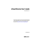
SCAN TOOL (MULTI USE TESTER { M.U.T.-III }
SUB ASSEMBLY)
M1001012400226
CAUTION
Turn the ignition switch to the "LOCK" (OFF) position
before disconnecting or connecting the scan tool.
NOTE: M.U.T.-III trigger harness is not necessary when pushing V.C.I. ENTER key.
VEHICLE COMMUNICATION
INTERFACE (V.C.I.)
M.U.T.-III USB CABLE
MB991824
M.U.T.-III MAIN HARNESS B
DO NOT USE
MB991827
M.U.T.-III MAIN HARNESS C
M.U.T.-III MAIN HARNESS A
MB991910
M.U.T.-III MEASUREMENT ADAPTER
DO NOT USE
MB991914
MB991911
MB991825
M.U.T.-III TRIGGER HARNESS
MB991826
AC2010881
AC21088AD
TSB Revision
00-22
GENERAL
PRECAUTIONS BEFORE SERVICE
HOW TO PERFORM VEHICLE IDENTIFICATION NUMBER (VIN) WRITING
CAUTION
The F.A.S.T-Key (Free-hand Advanced Security
Transmitter) is described as the Keyless Operation System (KOS) in this manual. (KOS is indicated as F.A.S.T. in the scan tool display.)
Follow the procedure below to register the VIN of the
Wireless Control Module (WCM) and the Keyless
Operation System (KOS).
Screen flow of scan tool (M.U.T.- III)
<When ECM is replaced>
M1001011400609
The VIN is stored in the engine control module
(ECM), WCM, and the KOS-ECU. If the VIN is
improperly erased, the engine warning light or the
keyless operation system warning indicator illuminate, and the diagnostic trouble code is displayed.
When the ECM, WCM, and the KOS-ECU are
replaced, follow the procedure below to write the
VIN.
<When WCM or KOS-ECU are replaced>
System Select
System Select
F.A.S.T./IMMO/Keyless/TPMS
F.A.S.T./IMMO/Keyless/TPMS
Special Function
Coding
VIN Registration
Key Code Registration
VIN Registration
Confirmation
OK
OK
Key Code Registration
Completed
VIN Registration
completed
OK
OK
Result of VIN
Registration
Engine VIN Registration
OK
Engine VIN Registration
Confirmation
OK
Engine VIN Registration
Completed
OK
Result of Engine
VIN Registration
AC700593 AE
WRITING PROCEDURE
Required Special Tools:
• MB991958: Scan Tool (M.U.T.-III Sub Assembly)
• MB991824: V.C.I.
• MB991827: M.U.T.-III USB Cable
• MB991910: M.U.T.-III Main Harness A
TSB Revision
GENERAL
PRECAUTIONS BEFORE SERVICE
00-23
CAUTION
Check that diagnostic trouble code P0603 "EEPROM fail"
is not set. When diagnostic trouble code P0603 "EEPROM
fail" is set, the ECM cannot store the key code even if the
key code is registered. If this diagnostic trouble code is
set, troubleshoot the ECM and repair. Then register the key
code to the ECM.
Data link connector
MB991910
MB991824
MB991827
AC608435 AB
System Select
System List
1
2
MPI/GDI/Diesel
Model Year
Up to 2005 MY
From to 2006 MY
F.A.S.T./IMMO/Keyless/TPMS
Vehicle Information
Model Name
Model Year
Model Code
3
AT/CVT/A-MT
4
ABS/ASC/ASTC
5
SAS
6
7
Multi Select 4WD
SRS Airbag
8
A/C
Loading Option Setup
OPC Option Name With Option
VF2 IMMOBI & Keyless & TPMS
9
ETACS
VF3 IMMOBI & F.A.S.T. & TPMS
10
Meter
CAUTION
Before connecting or disconnecting the MB991958: Scan
Tool, turn the ignition switch to the "LOCK" (OFF) position.
Connect scan tool MB991958 to the 16-pin data link connector
as follows.
NOTE: For details on how to use scan tool MB991958, refer to
the "M.U.T.-III Owner's Manual."
1. Ensure that the ignition switch is at the "LOCK" (OFF)
position.
2. Start up the personal computer.
3. Connect special tool MB991827 to special tool MB991824
and the personal computer.
4. Connect special tool MB991910 to the special tool
MB991824.
5. Connect special tool MB991910 to the data link connector of
the vehicle.
6. Turn the special tool MB991824 power switch to the "ON"
position.
NOTE: When the special tool MB991824 is energized, the
special tool MB991824 indicator light will be illuminated in a
green color.
7. Start the "M.U.T.-III system" on the personal computer and
turn the ignition switch to the "ON" position.
8. Select "F.A.S.T./IMMO/Keyless/TPMS" button from the
"System Select" screen. Then, select the applicable option
code item and push the OK button.
9. Select "Special Function" on the next screen.
Select Model Year and System
OK button
AC609809 AB
TSB Revision
00-24
GENERAL
PRECAUTIONS BEFORE SERVICE
Option: When IMMOBI & F.A.S.T. & TPMS is selected
10.Select "ENG key code & VIN Reg." from the "Special
Function" screen.
AC802950AB
Option: When IMMOBI & Keyless & TPMS is selected
AC802949AB
11.Push the OK button after "ENG key code & VIN Reg." is
displayed.
12.Push the OK button after "Completed. Press the OK button
and move to VIN writing function." is displayed.
OK button
AC709286AB
13.Enter the VIN of registering vehicle and push the OK button.
14.Push the OK button after "VIN Writing will start. Are you
sure?" is displayed.
15.Return to the previous screen and "In Progress" is displayed
at the lower-left corner on the screen.
16.Push the OK button after "Completed." is displayed.
AC709287
AC709285
17.VIN writing result is displayed.
18.Complete the scan tool MB991958.
19.Disconnecting the scan tool MB991958 is the reverse of the
connecting sequence, making sure that the ignition switch is
at the "LOCK" (OFF).
20.Push the OK button after "Completed." is displayed.
21.Terminate the scan tool MB991958.
22.Turn the ignition switch to the "LOCK" (OFF) position and
then disconnect scan tool MB991958.
TSB Revision
GENERAL
PRECAUTIONS BEFORE SERVICE
00-25
VIN WRITING STEPS FOR WCM AND KOS-ECU
CAUTION
Before the VIN registration to WCM and KOS-ECU, check
that the VIN of ECM and vehicle are matched.
CAUTION
Check that diagnostic trouble code B2416 "ECU internal
error" is not set. When diagnostic trouble code B2416
"ECU internal error" is set, the WCM and the KOS-ECU
cannot store the VIN even if the VIN is written. If this diagnostic trouble code is set, troubleshoot the WCM or the
KOS-ECU and repair. Then write the VIN to the WCM or the
KOS-ECU.
Data link connector
MB991910
MB991824
MB991827
AC608435 AB
System Select
System List
1
2
MPI/GDI/Diesel
Model Year
Up to 2005 MY
From to 2006 MY
F.A.S.T./IMMO/Keyless/TPMS
Vehicle Information
Model Name
Model Year
Model Code
3
AT/CVT/A-MT
4
ABS/ASC/ASTC
5
SAS
6
7
Multi Select 4WD
SRS Airbag
8
A/C
Loading Option Setup
OPC Option Name With Option
VF2 IMMOBI & Keyless & TPMS
9
ETACS
VF3 IMMOBI & F.A.S.T. & TPMS
10
Meter
CAUTION
Before connecting or disconnecting the MB991958: Scan
Tool, turn the ignition switch to the "LOCK" (OFF) position.
Connect scan tool MB991958 to the 16-pin data link connector
as follows.
NOTE: For details on how to use scan tool MB991958, refer to
the "M.U.T.-III Owner's Manual."
1. Ensure that the ignition switch is at the "LOCK" (OFF)
position.
2. Start up the personal computer.
3. Connect special tool MB991827 to special tool MB991824
and the personal computer.
4. Connect special tool MB991910 to the special tool
MB991824.
5. Connect special tool MB991910 to the data link connector of
the vehicle.
6. Turn the special tool MB991824 power switch to the "ON"
position.
NOTE: When the special tool MB991824 is energized, the
special tool MB991824 indicator light will be illuminated in a
green color.
7. Start the "M.U.T.-III system" on the personal computer and
turn the ignition switch to the "ON" position.
8. Select "F.A.S.T./IMMO/Keyless/TPMS" button from the
"System Select" screen. Then, select the applicable option
code item and push the OK button.
9. Select "Coding" on the next screen.
Select Model Year and System
OK button
AC609809 AB
TSB Revision
00-26
GENERAL
PRECAUTIONS BEFORE SERVICE
10.Select "VIN Writing" on "Coding" screen.
System Select F.A.S.T./IMMOBI/Keyless/TPMS
Coding
VIN Writing
Please select function.
AC609799AB
F.A.S.T./IMMOBI/Keyless/TPMS Coding
11.Push the OK button after the VIN written in the engine
control module is displayed.
12.Push the OK button after "VIN Writing will start. Are you
sure?" is displayed.
13.Push the OK button after "Completed." is displayed.
VIN Writing
VIN Writing
VIN (Engine ECU)
00000000000000000
*****************
VIN currently written in ECM is displayed.
Write the number displayed on the screen in Immobilizer KOS/ECU.
OK button
Press the OK button to execute.
AC609798 AC
F.A.S.T./IMMOBI/Keyless/TPMS
Coding
14.Result of VIN writing is displayed.
15.Resister the other ID code. (Refer to GROUP 42B,
Troubleshooting −ID Code Registration Judgment Table
P.42B-11 <Vehicles with KOS> or GROUP 42C,
Troubleshooting −ID Code Registration Judgment Table
P.42C-9 <Vehicles with WCM>.)
VIN Writing
Result of VIN Writing
VIN Writing
00000000000000000
*****************
AC609285AC
CODING LIST
M1001015000937
CAUTION
With the ETACS functions being customized, if any of the
ETACS-ECU variant coding and option coding items are
changed, the customized contents are reset. In such case,
the functions need to be recustomized.
Before troubleshooting, check that the coding data written into
the engine control module, TC-SST-ECU and ETACS-ECU are
normal. If they are not the same as the initial settings, various
functions and systems will not work correctly.
VARIANT CODING
Required Special Tools:
• MB991958: Scan Tool (M.U.T.-III Sub Assembly)
• MB991824: Vehicle Communication Interface (V.C.I.)
• MB991827: M.U.T.-III USB Cable
• MB991910: M.U.T.-III Main Harness A (Vehicles with
CAN communication system)
TSB Revision
GENERAL
PRECAUTIONS BEFORE SERVICE
00-27
The coding data can be checked by operating scan tool
MB991958.
NOTE: For details on how to use the scan tool MB991958,
refer to the "M.U.T.-III Owner’s manual".
Data link connector
MB991910
MB991824
MB991827
AC608435 AB
CAUTION
To prevent damage to scan tool MB991958, always turn the
ignition switch to the "LOCK" (OFF) position before connecting or disconnecting scan tool MB991958.
1. Ensure that the ignition switch is at the "LOCK" (OFF)
position.
2. Start up the personal computer.
3. Connect special tool MB991827 to special tool MB991824
and the personal computer.
4. Connect special tool MB991910 to special tool MB991824.
5. Connect special tool MB991910 to the data link connector.
6. Turn the power switch of special tool MB991824 to the "ON"
position.
NOTE: When special tool MB991824 is energized, special
tool MB991824 indicator light will be illuminated in a green
color.
7. Start the "M.U.T.-III system" on the personal computer.
8. Turn the ignition switch to the "ON" position.
9. Select "System select" from the start-up screen.
10.Select "From 2006 MY" under "Model Year". Check that
"Vehicle Information" contents are correct.
11.On the system list screen, select "MPI/GDI/DIESEL" to
check the engine control module data,
"AT/CVT/A-MT/TC-SST" to check the TC-SST-ECU data,
and "ETACS" to check the ETACS-ECU data.
NOTE: If "Loading Option Setup" list is shown, click appropriate box.
12.Select "Coding."
13.Select "Coding information & copy."
14.If the displayed coding information is different from the
corresponding initial setting in the list, replace the ECU with
a correctly coded one. For replacement of the engine control
module, refer to GROUP 13A, Engine Control Module
P.13A-888. For replacement of the TC-SST-ECU*, refer to
GROUP 22C, Transaxle Assembly P.22C-412. For
replacement of the ETACS-ECU, refer to GROUP 54A,
ETACS P.54A-742.
NOTE: *: TC-SST-ECU cannot be disassembled. Thus,
replace the transaxle assembly.
TSB Revision
00-28
Item name
GENERAL
PRECAUTIONS BEFORE SERVICE
ENGINE CONTROL MODULE CODING DATA LIST
Initial value
Final gear ratio
5MT/6MT <5M/T>
4.062 <TC-SST>
Tire circumference
2026mm
IMMOBILIZER
Present
ABS
Not present
A.S.C.
Present
S/W variation
No.1
Item name
TC-SST-ECU CODING DATA LIST
Initial value
Vehicle line
LANCER EVO
Destination
U.S.
Tire size
245/40R18
Cruise control
Present
A.S.C.
Present
Turbo charger
T/C(INCONEL-AL)
Item name
ETACS-ECU CODING DATA LIST
Initial value
Vehicle line
LANCER EVO
Model year
(Displays the model year)
SST oil cooling fan
Not present
Destination
U.S.
Transaxle
5MT <5M/T>
TC-SST <TC-SST>
Engine type
2.0L D4 VVT T/C
Engine power
Normal
Handle side
LHD
Chassis Type for A.S.C.
Type 1
OSS
Not present
Final drive
AWD FF Base
Transfer
ACD
IG off delay control
Disabled <5M/T>
Enable <TC-SST>
Dead lock operation customize
Disabled
After wipe customize
Enabled(def.D)
Tire circumference
2026mm
TSB Revision
GENERAL
PRECAUTIONS BEFORE SERVICE
Item name
Initial value
Fuel tank
Not used
DRL*1 type
Dimming DRL w/ P <halogen type>
IndependentDRL/P <discharge type>
Smart entry system
Not present or Type A or Type C
TPMS*1
Present
Keyless entry*2
Present
Air bag Auto Hazard
Not Present
Immobilizer
Type B <Vehicles for USA>
Type A <Vehicles for CANADA>
Cruise control
Present
Corner sensor
Not present
Headlight auto leveling device
Not present
Oil level warning
Not present
Water separate warning
Not present
Speed meter scale
Not used
Idle neutral control
Not used
Theft alarm sensor
Not present
T/M oil cooler
Not present
Theft sensor gain setting
Type 1
Side air bag
Present
ACC power auto cut
Default enabled
Number of speaker*2
Speaker less or Premium or 6 speakers
Seat material*2
Fabric or Leather
Auto light control*2
No/Cng Ng or Hi RLS/chg Ng
Front differential
Helical
Rear differential
AYC
Power window type
Type P4
Sun roof type
Not present or Type S4
WCM
Present
OCM
Present
ORC
Present
A/C
Present
AUDIO*2
Not present or Present
AND*2
Not present or Present
Siren answer
Disabled
TSB Revision
00-29
00-30
GENERAL
PRECAUTIONS BEFORE SERVICE
Item name
Initial value
Theft alarm siren
Not present
CAMERA
Not present
Corner sensor control unit
Not present
Electric Slide door (Left)
Not present
Electric Slide door (Right)
Not present
ETG
Not present
ESS ECU
Not present
HFM*2
Not present or Present
Intelligent washer customize
Enabled(def.E)
Headlight Leveling system type
Type1/No present
Rear wiper mode
Without Lo cntl
10MY SPEC
Enable
Rear wiper by reverse customize
Disabled
ABS
Not present
A.S.C.
Present
Auto fold mirror
SPD/Not present
SAS
Present
4WD/AWC
Not present
TCM
Not present <5M/T>
Present <TC-SST>
ACTV_STB
Not used
Door unlock by IG lock customize
Enabled(def.D)
Rheostat cancel mode
Available
EPS
Not present
ACDAYC
Present
Coming home light customize
Enabled(def.E)
Welcome light customize
Enable(d.Small)
Indirect light
Not present
Power window Dr
Present
Power window As
Not present
Power window RR
Not present
Power window RL
Not present
ESS by stoplight
Not present
Sun roof
Not present or Present
RLS*2
Not present or Present
TSB Revision
GENERAL
PRECAUTIONS BEFORE SERVICE
Item name
Initial value
Washer function improvement
Disabled
IG key illumination
W/ getting off
Turn signal bulb
21W+21W+5W
Rear wiper
Disabled
Fold mirror
Disabled
Headlight
4 beams*3
Comfort Hazard
Disabled
Headlight washer
Disabled
Front fog light mode
A spec.
Front fog light*2
Present
Rear fog light*2
NotPresent/ChgOk
Room light delay timer /door&H/L
Long
Room light by H/L
Full
Gate/Trunk light
Mode-1 (trunk)
Headlight auto cut mode
C-spec
Headlight auto cut
Enable
Door lock system
A-spec(NAS)
Auto door lock/unlock
Disabled
key remainder unlock
B-spec/Dr and As
Horn type*2
Dual horn
Gate/trunk opener mode
Present
Cooling fan
Relay control
Security alarm mode
C-spec
Security alarm function
Present/Chg Ng
Pre-alarm
Not present
Multi mode RKE
Disabled
Gate/Trunk
Trunk type
Manner Switch
NotPresent/ChgNg
Remote engine starter*2
Present/Chg Ok
Panic Alarm
Enable
Roomlight improvement
Enable
Front wiper
Speed Sensitive or Rain Sensitive
Comfort flasher type
Present/Chg Ok
Dome light center switch
Not present
Wiper washer check bulb*2
Present
TSB Revision
00-31
00-32
GENERAL
PRECAUTIONS BEFORE SERVICE
Item name
Initial value
AUDIO/S.RADIO type
AM 1kHz step or Other
H/L leveling type
Not present
AFS/ACL*1 type
Not present
ESS by turn light
Not present
Compressor type*2
No compressor or Scroll 90cc
Temperature type
Celsius or Fahrenheit
Rear view camera
Not present
Nose view camera
Not present
Side view camera
Not present
Average speed
Available
Vehicle language status
English
Fuel amount
Not used
Fuel consumption scale
L/100km <Vehicles for USA>
MPG(US) <Vehicles for CANADA>
Speed gauge tolerance
U.S.
Coolant temp gauge threshold
Normal
Frost warning threshold
U.S.
Distance to empty
Available
Average fuel consumption
Available
Instant fuel consumption
Available
Time traveled
Not available
Distance traveled
Not available
Fuel used
Not available
Trip autoreset IG OFF
Available
Variable Speed Alarm
Not available
Rest reminder
Available
Instant speed
Not available
Seat belt reminder control type
AABT
Seat belt reminder flashing
Available
Seat belt reminder indicator
D&P independent
Reverse alarm
Not available
Key reminder
Available
Lighting monitor
Available
GCC speed alarm
Not available
Condition tone alarm
Not available
TSB Revision
GENERAL
PRECAUTIONS BEFORE SERVICE
Item name
Initial value
Rent-a-car mode IG-OFF always
Available
Rent-a-car mode IG-OFF door open
Available
Service reminder schedule table
NAS 20
ACD control display
Not used
TPMS information
32 psi
Horn chirp by keyless
Present/Chg Ok
Rear S/R Unlock Output
Not present
Trailer turn detection
Present
Shift Lever
Not present <5M/T>
00-33
Present <TC-SST>
AFS/ACL/Leveling
Not present
Satellite Radio*2
Not present or Present
Display opening type
MMC
F.A.S.T. auto lock customize
Not used
DRL function
Present/Chg Ng
FACU
Not present
S-AWC Control display
Available
Diesel particulate filter
Not present
Language mode
Not available or Available
WSS
Not present
Door Unlock Mode Customize*2
Disabled
RLS overwipe type
Type 1
RLS WS type
Type 2 (Green)
Interior illumination customize
Disabled
NOTE: .
• *1: TPMS is an abbreviation of Tire Pressure Monitoring
System, DRL of Daytime Running Light and AFS of Adaptive Front lighting System.
• *2: The setting can be changed by the option coding. Refer
to .
• *3: Although the dual-light discharge type is employed, it is
displayed as "4 beams"
TSB Revision
00-34
GENERAL
PRECAUTIONS BEFORE SERVICE
OPTION CODING
CAUTION
• If there is any item indicated by the option coding after
equipment change, set ETACS-ECU so that the option
coding data corresponds with the equipment content.
Functions and systems do not work normally if the setting does not correspond with the equipment.
• With the ETACS functions being customized, if any of
the ETACS-ECU variant coding and option coding items
are changed, the customized contents are reset. In
such case, the functions need to be recustomized.
The ETACS-ECU option coding data can be checked or
changed by operating scan tool MB991958.
• How to check option coding data
1. Connect the scan tool MB991958. Refer to P.00-26.
2. Turn the ignition switch to the "ON" position.
3. Select "System select" from the start-up screen.
4. Select "From 2006 MY" under "Model Year". Check that
"Vehicle Information" contents are correct.
5. Select "ETACS" from "System List", and then press
"OK" button.
NOTE: If "Loading Option Setup" list is shown, click
appropriate box.
6. Select "Coding."
7. Select "Option Coding Information."
8. Check the displayed option coding information.
• How to change option coding data
1. Connect the scan tool MB991958. Refer to P.00-26.
2. Turn the ignition switch to the "ON" position.
3. Select "System select" from the start-up screen.
4. Select "From 2006 MY" under "Model Year". Check that
"Vehicle Information" contents are correct.
5. Select "ETACS" from "System List", and then press
"OK" button.
NOTE: If "Loading Option Setup" list is shown, click
appropriate box.
6. Select "Coding."
7. Select "Option Coding."
8. Change to correct option coding data.
TSB Revision
00-35
GENERAL
PRECAUTIONS BEFORE SERVICE
LIST
Item name
Number of speaker
Seat material
Auto light CNTL
AUDIO (CAN)
AND
HFM (hands free-ECU)
Rain Light Sensor
Front fog light
Rear fog light
Horn type
Remote engine starter
Wiper washer check bulb
Compressor type
Satellite Radio
Keyless
Door Unlock Mode Customize
INITIALIZATION PROCEDURE FOR LEARNING
VALUE IN MFI ENGINE
M1001011700826
When the following service is performed, initialize the learning
value.
• At replacing engine assembly
• At replacing throttle body and at cleaning
• At replacing knock sensor
.
INITIALIZATION PROCEDURE
Required Special Tools:
• MB991958: Scan Tool (M.U.T.-III Sub Assembly)
• MB991824: V.C.I.
• MB991827: M.U.T.-III USB Cable
• MB991910: M.U.T.-III Main Harness A
TSB Revision
00-36
GENERAL
PRECAUTIONS BEFORE SERVICE
CAUTION
To prevent damage to scan tool MB991958, always turn the
ignition switch to the "LOCK" (OFF) position before connecting or disconnecting scan tool MB991958.
1. After the ignition switch is in "LOCK" (OFF) position, connect
scan tool MB991958 to the data link connector.
2. Turn the ignition switch to the "ON" position.
3. Select "MFI" from System select Screen of scan tool
MB991958.
4. Select "Special Function" from MFI Screen.
5. Select "Learned value reset" from Special Function Screen.
6. Select "All learned value" from Learned value reset Screen
7. Initialize the learning value by pressing the "OK" button.
8. After initializing the learning value, the learning value of MFI
engine idling is necessary. (Refer to Learning Procedure For
Idling In MFI Engine P.00-36).
Data link connector
MB991910
MB991824
MB991827
AC608435 AB
ENGINE IDLING LEARNING PROCEDURE
M1001011800920
PURPOSE
When the ECM is replaced, or when the learned value is initialized, the idle may not be stabilized. Carry out the learning
method by following the procedures below.
LEARNING PROCEDURE
1. Start the engine and warm to reach 80° C (176° F) or more.
NOTE: When the engine coolant temperature is 80° C
(176° F) or more, the warm-up is not needed if the ignition
switch is in "ON" position once.
2. Turn the ignition switch to "LOCK" (OFF) position.
3. After 10 seconds or more, start the engine again.
4. For 10 minutes, carry out the idling under the condition
shown below and then confirm the engine idles normally.
• Transaxle: Neutral (P range on vehicles with TC-SST)
• Operation in ignition-related, fan and attachments: Not to be
operated
• Engine coolant temperature: 80° C (176° F) or more
NOTE: If the engine stalls while idling, check for a dirty (on
the throttle valve) of the throttle body and clean if needed.
Then perform the service from Procedure 1 again.
TSB Revision
GENERAL
PRECAUTIONS BEFORE SERVICE
00-37
INITIALIZATION PROCEDURE FOR THROTTLE
ACTUATOR CONTROL MOTOR
When the battery cable is disconnected and reconnected, throttle actuator control motor valve (Fully closed position) is eliminated, so that the throttle valve opening angle control would not
be performed correctly. When the battery cable is disconnected
and reconnected, initialize the throttle actuator control motor
using the following procedure.
1. Turn the ignition switch to the "ON" position then, turn the
ignition switch to "LOCK" (OFF) position.
2. For 10 seconds or more, keep the ignition switch in "LOCK"
(OFF) position.
TIMING CHAIN MAINTENANCE
M1001016500269
.
If the vehicle equipped with 2.0 L turbocharged engine continues the rough driving like competitive running*1, the amount of
carbon mixed into the engine oil tends to increase. This can
possibly cause the timing chain to gradually elongate. To prevent this, the function or logic monitoring the amount of elongation of the timing chain is integrated into the ECM. When the
ECM detects the elongation of the timing chain, the warning is
shown on the multi-information display of combination meter as
shown in the illustration. This gives the driver the information
that the visual check of the elongation of the timing chain is
AK801166
necessary. If this warning is continuously neglected, the timing
chain can possibly interfere with the other engine components,
resulting in the engine damaged.
NOTE: *1: The competitive running means the running that
constantly repeats the cycle of the full opened position of the
accelerator pedal and the full closed position of the accelerator
pedal.
The ECM stores the timing chain conditions as the initial learning value when the timing chain is installed.
The ECM stores the amount of elongation of the timing chain in the EEPROM as the current learning value,
compared with the initial learning value. The ECM judges that the visual check of the elongation of the timing
chain is necessary when the current learning value exceeds the specified value. Thus, use the scan tool
MB991958 to always carry out the maintenance of the initial learning value related to the timing chain that is
stored by the ECM after the following service.
TSB Revision
00-38
GENERAL
PRECAUTIONS BEFORE SERVICE
Service
Maintenance items
by scan tool
MB991958
Maintenance purpose
ECM replacement
• Learned value
Read&Save *2
• Write learned
value (Changed
ECU)*2
The purpose is that the initial learning value regarding the
amount of elongation of the timing chain stored by the
current ECM is loaded in the scan tool MB991958, and
then written into the new ECM. This allows the ECM to
appropriately monitor the amount of elongation of the
timing chain after the ECM replacement.
Visual check of
elongation of timing
chain
Learned value reset
The purpose is that the initial learning value stored by the
current ECM is initialized after the visual check of the
elongation of the timing chain by illuminating the warning
lamp, whether or not the timing chain is replaced. This
allows the ECM to appropriately monitor the amount of
elongation of the timing chain.
Timing chain or
engine assembly
replaced
Learned value reset
The purpose of this procedure is that the initial learning
value stored by the current ECM is initialized when the
timing chain or the engine assembly (the timing chain is
also replaced with a new one.) is replaced. This allows the
ECM to appropriately monitor the amount of elongation of
the timing chain.
NOTE: *2: The visual check of the elongation of the timing chain must be carried out under the following conditions: when the initial learning value cannot be written into scan tool MB991958 from the current ECM
because of the ECM malfunction and when the initial learning value cannot be written into the new ECM
(Refer to GROUP 11A, On-vehicle Service −Timing Chain Elongation Visual Check P.11A-17). If elongated
more than the specified length at this time, the timing chain can possibly interferes with the other engine components before the new ECM detects the elongation of the timing chain. The timing chain must be replaced
with a new one to prevent engine damage.
LEARNED VALUE READ&SAVE AND WRITE
LEARNED VALUE (CHANGED ECU)
Required Special Tools:
• MB991958: Scan Tool (M.U.T.-III Sub Assembly)
• MB991824: V.C.I.
• MB991827: M.U.T.-III USB Cable
• MB991910: M.U.T.-III Main Harness A
TSB Revision
GENERAL
PRECAUTIONS BEFORE SERVICE
Data link connector
MB991910
MB991824
MB991827
AC608435 AB
00-39
CAUTION
To prevent damage to scan tool MB991958, always turn the
ignition switch to the "LOCK" (OFF) position before connecting or disconnecting scan tool MB991958.
1. After the ignition switch is in "LOCK" (OFF) position, connect
scan tool MB991958 to the data link connector.
2. Turn the ignition switch to the "ON" position.
3. Select "MFI" from System select Screen of scan tool
MB991958.
4. Select "Special Function" from MFI Screen.
5. Select "Timing chain maintenance" from Special Function
Screen.
6. Select "Learned value Read&Save" from Timing chain
maintenance Screen.
7. Press "OK" to store the initial learning value file.
NOTE: When the initial learning value file is appropriately
stored, "Learned value Save Complete" is shown on the screen
of the scan tool MB991958.
NOTE: Calculating the amount of elongation of the timing chain
by the ECM takes the time. Thus, the file cannot be stored for a
while after the ECM initialization or replacement.
8. Replace the ECM.
9. Select "Write learned value (Changed ECU)" from Timing
chain maintenance Screen.
10.Select the initial learning value file stored during Step 7 to
write the initial learning value.
NOTE: Use only the initial learning value file stored during Step
7 without using any other files.
NOTE: When the initial learning value is appropriately written,
"Learned value writing Completed." is shown on the screen of
the scan tool MB991958.
LEARNED VALUE RESET
Required Special Tools:
• MB991958: Scan Tool (M.U.T.-III Sub Assembly)
• MB991824: V.C.I.
• MB991827: M.U.T.-III USB Cable
• MB991910: M.U.T.-III Main Harness A
TSB Revision
00-40
GENERAL
PRECAUTIONS BEFORE SERVICE
CAUTION
To prevent damage to scan tool MB991958, always turn the
ignition switch to the "LOCK" (OFF) position before connecting or disconnecting scan tool MB991958.
1. After the ignition switch is in "LOCK" (OFF) position, connect
scan tool MB991958 to the data link connector.
2. Turn the ignition switch to the "ON" position.
3. Select "MFI" from System select Screen of scan tool
MB991958.
4. Select "Special Function" from MFI Screen.
5. Select "Timing chain maintenance" from Special Function
Screen.
6. Select "Learned value reset" from Timing chain
maintenance Screen.
7. Press "OK" to reset the initial learning value.
Data link connector
MB991910
MB991824
MB991827
AC608435 AB
TEST/LIMIT VALUE READOUT
Required Special Tools:
• MB991958: Scan Tool (M.U.T.-III Sub Assembly)
• MB991824: V.C.I.
• MB991827: M.U.T.-III USB Cable
• MB991910: M.U.T.-III Main Harness A
TSB Revision
GENERAL
PRECAUTIONS BEFORE SERVICE
CAUTION
To prevent damage to scan tool MB991958, always turn the
ignition switch to the "LOCK" (OFF) position before connecting or disconnecting scan tool MB991958.
1. After the ignition switch is in "LOCK" (OFF) position, connect
scan tool MB991958 to the data link connector.
2. Turn the ignition switch to the "ON" position.
3. Select "MFI" from System select Screen of scan tool
MB991958.
4. Select "Special Function" from MFI Screen.
5. Select "Timing chain maintenance" from Special Function
Screen.
6. Select "Test/Limit value readout" from Timing chain
maintenance Screen.
7. Read the value of percentage (%) shown on the screen.
NOTE: The value of percentage (%) shown on the screen is the
amount of elongation of the timing chain calculated by the ECM
based on the initial learning value, and thus is not the actual
amount. Use this for the reference only.
Data link connector
MB991910
MB991824
MB991827
00-41
AC608435 AB
SERVICING ELECTRICAL SYSTEM
M1001011900433
WARNING
Battery posts, terminals and related accessories contain lead and lead compounds. WASH HANDS AFTER
HANDLING.
1. Note the following before proceeding with working on the
electrical system.
Never perform unauthorized modifications to any electrical
device or wiring. Such modifications might lead to a vehicle
malfunction, over-capacity or short-circuit that could result in
a fire in the vehicle.
ACX00880AB
TSB Revision
00-42
GENERAL
PRECAUTIONS BEFORE SERVICE
CAUTION
• Before connecting or disconnecting the negative battery cable, be sure to turn the ignition switch to the
"LOCK" (OFF) position and turn off the lights (If this is
not done, there is the possibility of semiconductor
parts being damaged).
• After completion of the work (and the negative battery
terminals is connected), warm up the engine and allow
it to idle for approximately 10 minutes under the conditions described below in order to stabilize engine control conditions, and then check to be sure that the idle
is satisfactory.
• Engine coolant temperature: 85 −95° C (185 −203° F)
• Lights and all accessories: OFF
• Transaxle: "P" position
• Steering wheel: straight-forward position
2. When servicing the electrical system, disconnect the
negative cable terminal from the battery.
HOW TO SHIFT LOCK FORCED RELEASE
M1001018100193
If the shift lever cannot be moved from the P position due to
discharged battery or similar reasons, release the shift lock by
observing the procedure below.
.
<TC-SST>
1. Remove the floor console box cup holder and the floor
console panel assembly (Refer to GROUP 52A −Floor
Console Assembly P.52A-10).
2. Turn the ignition switch to the position other than the LOCK
(OFF) position.
3. Insert a screwdriver or a similar tool from the section "A"
shown in the figure. While pressing the shift lock forced
release switch, move the shift lever.
A
Parking brake lever
AC808409AB
Shift lock release
switch
AC808410AD
TSB Revision
00-43
GENERAL
PRECAUTIONS BEFORE SERVICE
VEHICLE WASHING
M1001012000660
1. If high-pressure car-washing equipment or steam car-washing equipment is used to wash the vehicle, be sure to maintain the spray nozzle at a distance of at least approximately
40cm (16 in.) from any plastic parts and all opening parts
(doors, luggage compartment, etc.).
2. If high-pressure car-washing equipment or steam car-washing equipment is used to wash the vehicle, be sure to
observe the following instructions to prevent damages to
the plastic parts.
• Spray nozzle distance: Approximately 40 cm (16 in.) or
more
• Spray pressure: 3,900 kPa or less
• Spray temperature: 82 ° C (180° F) or less
• Time of intensive spraying to one point: Within 30 seconds
Approximately
40 cm (16 in.) or more
ACX00881AK
APPLICATION OF ANTI-CORROSION AGENTS
AND UNDERCOATS
M1001011000117
Be careful not to apply oil or grease to the heated oxygen sensor. If applied, the sensor may malfunction. Protect the heated
oxygen sensor with a cover before applying anti-corrosion
agent, etc.
BOLTS AND NUTS WITH STABILIZER FOR
COEFFICIENT OF FRICTION
M1001014800082
The bolts and nuts with stabilizer for coefficient of friction have
been used for the connections such as the suspension arm and
crossmember in order to stabilize the axial force and to ensure
the high axial force at bolt/nut connections, resulting in
improved reliability.
NOTE: The bolts and nuts with stabilizer for coefficient of friction mean that the bolts and nuts with surface treatment to stabilize and reduce the coefficient of friction, allowing to achieve
the stable axial force and to secure the high axial force with low
tightening torque.
FORM−IN−PLACE GASKET (FIPG)
.
M1001014200176
The engine has several parts to which the form-in-place gasket
(FIPG) is used. To sufficiently achieve the aims of this gasket, it
is necessary to pay attention to the application amount, procedure, and surface status.
If the application amount is too small, a leakage will occur. If the
application amount is excessive, the FIPG will overflow and
cause a clogging or narrowing of water and oil paths. Therefore, to eliminate the leak from the joint, it is indispensable that
the FIPG be applied with a correct amount and without any
gap.
TSB Revision
00-44
GENERAL
PRECAUTIONS BEFORE SERVICE
Because the FIPG used for the engine parts becomes hardened by the reaction with the atmospheric moisture, it is normally used for the metal flange section.
.
CAUTION
Reapply the FIPG with care to the followings.
1. Completely remove the old FIPG including the residue
in gaps of parts.
2. Using Mitsubishi genuine parts cleaner (MZ100387) or
equivalent, degrease the FIPG application surface carefully.
3. According to the FIPG application procedures, apply it
accurately.
.
DISASSEMBLY
The parts installed with the FIPG can be disassembled easily
without using any special method. However, in some cases, it
is necessary to tear the sealant in between the mating surfaces
by tapping the parts with a wooden hammer or similar tools. It is
acceptable to lightly hit in a smooth, thin gasket scraper into the
mating surface, but, in this case, a sufficient caution is required
not to damage the mating surface. The oil pan FIPG cutter
(Special tool: MD998727) is provided. Thus, use this special
tool.
.
GASKET SURFACE CLEANING
Use a gasket scraper or wire brush to completely remove all
the foreign materials adhering to the gasket surface. Check
that the FIPG application surface is smooth. There must be no
grease or foreign material adhesion to the gasket surface. Do
not forget to remove the old FIPG remaining in the mounting
hole and tapped hole.
.
APPLICATION PROCEDURE
Apply the FIPG with a specified diameter and without any gap.
Completely enclose around the mounting hole. When the FIPG
is not hardened, it can be wiped off. When the FIPG is still
moistened (within three minutes), perform the installation to the
specified position. At the time of installation, prevent the FIPG
from adhering to locations other than it is necessary. After the
installation, until a sufficient period of time (approximately for
two hours) elapses, do not contact the oil or water to the application area. Also, do not start the engine. Because the FIPG
application procedure may differ depending on the application
area, apply the FIPG according to the procedure described in
the text.
TSB Revision
00-45
GENERAL
TOWING AND HOISTING
TOWING AND HOISTING
M1001000800755
WRECKER TOWING RECOMMENDATION
.
FRONT TOWING PICKUP
SLING TYPE
WHEEL LIFT TYPE
FLAT BED TYPE
CAUTION
• The vehicle must not be towed by placing only its front
wheels on a rolling dolly, because to do so will result in
deterioration of the viscous coupling and in the viscous coupling causing the vehicle to jump forward suddenly.
• If this vehicle is towed, use flat bed equipment
NO
NO
OK
AC000070AI
.
REAR TOWING PICKUP
SLING TYPE
WHEEL LIFT TYPE
FLAT BED TYPE
CAUTION
• The vehicle must not be towed by placing only the rear
wheels on a rolling dolly, because to do so will result in
deterioration of the viscous coupling causing the vehicle to jump forward suddenly.
• If this vehicle is towed, use flat bed equipment.
NO
NO
OK
AC611522AC
.
TSB Revision
00-46
GENERAL
TOWING AND HOISTING
TOWING WHEN KEYS ARE NOT AVAILABLE
When a locked vehicle must be towed and keys are not available, the vehicle may be lifted and towed from the front, provided the parking brake is released. If not released, the rear
wheels should be placed on a tow dolly.
.
SAFETY PRECAUTIONS
The following precautions should be taken when towing the
vehicle:
1. Do not lift or tow the vehicle by attaching to or wrapping
around the bumper.
2. Any loose, protruding, or damaged parts such as hoods,
doors, fenders, trim, etc. should be secured or removed
prior to moving the vehicle.
3. Refrain from going under a vehicle when it is lifted by the
towing equipment, unless the vehicle is adequately supported by safety stands.
4. Never allow passengers to ride in a towed vehicle.
5. State and local rules and regulations must be followed when
towing a vehicle.
LIFTING, JACKING SUPPORT LOCATION
.
FLOOR JACK AND RIGID RACK
CAUTION
• Never place a support at any point other than the specified one, or that point will be deformed.
• For lifting, put rubber or similar material between the
side sill and rigid rack, otherwise the side sill area will
be damaged.
TSB Revision
00-47
GENERAL
TOWING AND HOISTING
FLOOR JACK
<FRONT>
<REAR>
Differential carrier
assembly
Center member
RIGID RACK
<FRONT>
<REAR>
Notch
Rubber
Notch
Rubber
AC709513AB
TSB Revision
00-48
GENERAL
TOWING AND HOISTING
.
POST TYPE
Special care should be taken when raising the vehicle on a
frame contact type hoist. The hoist must be equipped with the
proper adapters in order to support the vehicle at the proper
locations.
CAUTION
When service procedures require removing rear suspension, fuel tank and spare tire, place additional weight on
the rear end of vehicle, or anchor vehicle to hoist to prevent tipping when the location of the center of gravity
changes.
Notch
Notch
AC709514 AB
TSB Revision
00-49
GENERAL
GENERAL DATA AND SPECIFICATIONS
GENERAL DATA AND SPECIFICATIONS
M1001000904680
.
VEHICLES FOR USA (INCLUDES PUERTO RICO)
8
4
2
7
5
6
9
3
1
AC710509AC
Item
CZ4AS
NGFZL2M
MGFZL2M
MPFZL2M
1
1,810 (71.3)
1,810 (71.3)
1,810 (71.3)
2
1,545 (60.8)
1,545 (60.8)
1,545 (60.8)
3
4,495 (177.0)
4,495 (177.0)
4,495 (177.0)
Overhang-front
4
910 (35.8)
910 (35.8)
910 (35.8)
Wheelbase
5
2,650 (104.3)
2,650 (104.3)
2,650 (104.3)
Overhang-rear
6
935 (36.8)
935 (36.8)
935 (36.8)
Ground clearance
7
140 (5.5)
140 (5.5)
140 (5.5)
Overall height (unladen)
8
1,480 (58.3)
1,480 (58.3)
1,480 (58.3)
Tread-rear
9
1,545 (60.8)
1,545 (60.8)
1,545 (60.8)
1,595 (3,517)
1,620 (3,572)
1,630 (3,594)
2,060 (4,542)
2,060 (4,542)
2,060 (4,542)
Gross axle weight rating-front
1,080 (2,381)
1,080 (2,381)
1,080 (2,381)
Gross axle weight rating-rear
1,050 (2,315)
1,050 (2,315)
1,050 (2,315)
Seating capacity
5
5
5
Engine
Model No.
4B11
4B11
4B11
Piston displacement cm3 (cu in)
1,998 (121.9)
1,998 (121.9)
1,998 (121.9)
Maximum output kW/r/min
(HP/r/min)
217/6,500
(291/6,500)
217/6,500
(291/6,500)
217/6,500
(291/6,500)
Maximum torque N⋅ m/r/min
(ft-lb/r/min)
407/4,000
(300/4,000)
407/4,000
(300/4,000)
407/4,000
(300/4,000)
Fuel system
Fuel supply system
MFI
MFI
MFI
Transaxle
Model No.
W5M6A
W6DGA
W6DGA
Type
5M/T
TC-SST
TC-SST
5.9 (19.4)
5.9 (19.4)
5.9 (19.4)
Vehicle
Overall width
dimension mm Tread-front
(in)
Overall length
Vehicle weight Curb weight
kg (lb)
Gross vehicle weight rating
Turning radius m (ft)
.
TSB Revision
00-50
GENERAL
GENERAL DATA AND SPECIFICATIONS
VEHICLES FOR CANADA
8
4
2
7
5
9
6
3
1
AC710509AC
Item
CZ4AS
NGFZL3M
MGFZL3M
MPFZL3M
1
1,810 (71.3)
1,810 (71.3)
1,810 (71.3)
2
1,545 (60.8)
1,545 (60.8)
1,545 (60.8)
3
4,495 (177.0)
4,495 (177.0)
4,495 (177.0)
Overhang-front
4
910 (35.8)
910 (35.8)
910 (35.8)
Wheelbase
5
2,650 (104.3)
2,650 (104.3)
2,650 (104.3)
Overhang-rear
6
935 (36.8)
935 (36.8)
935 (36.8)
Ground clearance
7
140 (5.5)
140 (5.5)
140 (5.5)
Overall height (unladen)
8
1,480 (58.3)
1,480 (58.3)
1,480 (58.3)
Tread-rear
9
1,545 (60.8)
1,545 (60.8)
1,545 (60.8)
1,595 (3,517)
1,620 (3,572)
1,630 (3,594)
2,060 (4,542)
2,060 (4,542)
2,060 (4,542)
Gross axle weight rating-front
1,080 (2,381)
1,080 (2,381)
1,080 (2,381)
Gross axle weight rating-rear
1,050 (2,315)
1,050 (2,315)
1,050 (2,315)
Seating capacity
5
5
5
Engine
Model No.
4B11
4B11
4B11
Piston displacement cm3 (cu in)
1,998 (121.9)
1,998 (121.9)
1,998 (121.9)
Maximum output kW/r/min
(HP/r/min)
217/6,500
(291/6,500)
217/6,500
(291/6,500)
217/6,500
(291/6,500)
Maximum torque N⋅ m/r/min
(ft-lb/r/min)
407/4,000
(300/4,000)
407/4,000
(300/4,000)
407/4,000
(300/4,000)
Fuel system
Fuel supply system
MFI
MFI
MFI
Transaxle
Model No.
W5M6A
W6DGA
W6DGA
Type
5M/T
TC-SST
TC-SST
5.9 (19.4)
5.9 (19.4)
5.9 (19.4)
Vehicle
Overall width
dimension mm Tread-front
(in)
Overall length
Vehicle weight Curb weight
kg (lb)
Gross vehicle weight rating
Turning radius m (ft)
TSB Revision
00-51
GENERAL
TIGHTENING TORQUE
TIGHTENING TORQUE
Each torque value in the table is a standard value for
tightening under the following conditions.
1. Bolts, nuts and washers are all made of steel and
plated with zinc.
2. The threads and bearing surface of bolts and
nuts are all in dry condition.
The values in the table are not applicable:
M1001001100964
1. If toothed washers are inserted.
2. If plastic parts are fastened.
3. If bolts are tightened to plastic or die-cast
inserted nuts.
4. If self-tapping screws or self-locking nuts are
used.
STANDARD BOLT AND NUT TIGHTENING
TORQUE
Thread size
Standard tightening torque
Nominal bolt
diameter (mm)
Pitch
(mm)
Head mark "4"
Head mark "7"
Head mark "8"
M5
0.8
2.5 ± 0.5 N⋅ m (23 ± 4
in-lb)
5.0 ± 1.0 N⋅ m (44 ± 9
in-lb)
6.0 ± 1.0 N⋅ m (53 ± 9
in-lb)
M6
1.0
5.0 ± 1.0 N⋅ m (44 ± 9
in-lb)
8.5 ± 1.5 N⋅ m (76 ± 13
in-lb)
10 ± 2 N⋅ m (89 ± 17
in-lb)
M8
1.25
11 ± 2 N⋅ m (98 ± 17
in-lb)
20 ± 4 N⋅ m (15 ± 3 ft-lb) 24 ± 4 N⋅ m (18 ± 3 ft-lb)
M10
1.25
23 ± 4 N⋅ m (17 ± 3 ft-lb) 42 ± 8 N⋅ m (31 ± 6
ft-lb)
53 ± 7 N⋅ m (39 ± 5 ft-lb)
M12
1.25
42 ± 8 N⋅ m (31 ± 6 ft-lb) 80 ± 10 N⋅ m (59 ± 7
ft-lb)
93 ± 12 N⋅ m (68 ± 9
ft-lb)
M14
1.5
70 ± 10 N⋅ m (52 ± 7
ft-lb)
130 ± 20 N⋅ m (96 ± 15
ft-lb)
150 ± 20 N⋅ m (111 ± 14
ft-lb)
M16
1.5
105 ± 15 N⋅ m (78 ± 11
ft-lb)
195 ± 25 N⋅ m (144 ± 18 230 ± 30 N⋅ m (170 ± 22
ft-lb)
ft-lb)
M18
1.5
150 ± 20 N⋅ m (111 ± 14 290 ± 40 N⋅ m (214 ± 29 335 ± 45 N⋅ m (247 ± 33
ft-lb)
ft-lb)
ft-lb)
M20
1.5
210 ± 30 N⋅ m (155 ± 22 400 ± 60 N⋅ m (295 ± 44 465 ± 65 N⋅ m (343 ± 48
ft-lb)
ft-lb)
ft-lb)
M22
1.5
290 ± 40 N⋅ m (214 ± 29 540 ± 80 N⋅ m (398 ± 59 630 ± 90 N⋅ m (465 ± 66
ft-lb)
ft-lb)
ft-lb)
M24
1.5
375 ± 55 N⋅ m (277 ± 40 705 ± 105 N⋅ m (520 ±
ft-lb)
77 ft-lb)
TSB Revision
820 ± 120 N⋅ m (605 ±
88 ft-lb)
00-52
GENERAL
LUBRICATION AND MAINTENANCE
FLANGE BOLT AND NUT TIGHTENING TORQUE
Thread size
Standard tightening torque
Nominal bolt
diameter (mm)
Pitch
(mm)
Head mark "4"
Head mark "7"
Head mark "8"
M6
1.0
5.0 ± 1.0 N⋅ m (44 ± 9
in-lb)
10 ± 2 N⋅ m (89 ± 17
in-lb)
12 ± 2 N⋅ m (107 ± 17
in-lb)
M8
1.25
13 ± 2 N⋅ m (111 ± 22
in-lb)
24 ± 4 N⋅ m (18 ± 3 ft-lb) 28 ± 5 N⋅ m (20 ± 4 ft-lb)
M10
1.25
26 ± 5 N⋅ m (19 ± 4 ft-lb) 50 ± 5 N⋅ m (37 ± 4 ft-lb) 58 ± 7 N⋅ m (43 ± 5 ft-lb)
M10
1.5
25 ± 4 N⋅ m (18 ± 3 ft-lb) 46 ± 8 N⋅ m (34 ± 6 ft-lb) 55 ± 5 N⋅ m (41 ± 3 ft-lb)
M12
1.25
47 ± 9 N⋅ m (35 ± 6 ft-lb) 93 ± 12 N⋅ m (68 ± 9
ft-lb)
105 ± 15 N⋅ m (78 ± 11
ft-lb)
M12
1.75
43 ± 8 N⋅ m (32 ± 6 ft-lb) 83 ± 12 N⋅ m (61 ± 9
ft-lb)
98 ± 12 N⋅ m (72 ± 9
ft-lb)
LUBRICATION AND MAINTENANCE
Maintenance and lubrication service recommendations have been compiled to provide maximum protection for the vehicle owner's investment against all
reasonable types of driving conditions. Since these
conditions vary with the individual vehicle owner's
driving habits, the area in which the vehicle is operated and the type of driving to which the vehicle is
subjected, it is necessary to prescribe lubrication and
maintenance service on a time frequency as well as
mileage interval basis.
Oils, lubricants and greases are classified and
graded according to standards recommended by the
Society of Automotive Engineers (SAE), the American Petroleum Institute (API) and the National Lubricating Grease Institute (NLGI).
MAINTENANCE SCHEDULES
Information for service maintenance is provided in
the "SCHEDULED MAINTENANCE TABLE." Three
schedules are provided; one for "Required Maintenance." one for "General Maintenance" and one for
"Severe Usage Service."
The item numbers in "SCHEDULED MAINTENANCE
TABLE" correspond to the section numbers in
"MAINTENANCE SERVICE."
SEVERE SERVICE
Vehicles operating under severe service conditions
will require more frequent service.
Component service information is included for vehicles operating under one or more of the following
conditions:
TSB Revision
M1001001200529
1. Trailer towing or police, taxi or commercial type
operation.
2. Operation of Vehicle
(1) Short-trip operation at freezing temperature
(engine not thoroughly warmed up)
(2) More than 50% operation in heavy city traffic
during hot weather above 32° C (90° F)
(3) Extensive idling
(4) Driving in sandy areas
(5) Driving in salty areas
(6) Driving in dusty conditions
(7) Driving off-road
ENGINE OIL
CAUTION
Test results submitted to EPA have shown that
laboratory animals develop skin cancer after prolonged contact with used engine oil. Accordingly,
the potential exists for humans to develop a
number of skin disorders, including cancer, from
such exposure to used engine oil. Therefore,
when changing engine oil, be careful not to touch
it as much as possible. Protective clothing and
gloves, that cannot be penetrated by oil, should
be worn. The skin should be thoroughly washed
with soap and water, or use waterless hand
cleaner, to remove any used engine oil. Do not
use gasoline, thinners, or solvents.
Either of the following engine oils should be used:
Engine oils displaying ILSAC certification symbol or
conforming to the API classification SM.
GENERAL
LUBRICATION AND MAINTENANCE
For further details, refer to "LUBRICANTS SELECTION."
LUBRICANTS AND GREASES
Semi-solid lubricants bear the NLGI designation and
are further classified as grades 0, 1, 2, 3, etc.
Whenever "Chassis Lubricant" is specified, Multipurpose Grease, NLGI grade Number 2, should be
used.
FUEL USAGE STATEMENT
CAUTION
Using leaded gasoline in this car will damage the
catalytic converters and heated oxygen sensors,
and affect the warranty coverage validity.
This vehicle must use unleaded gasoline only.
This vehicle has a fuel filler tube which is especially
designed to accept only the smaller-diameter
unleaded gasoline dispensing nozzle.
00-53
Gasohol: A mixture of 10% ethanol (grain alcohol)
and 90% unleaded gasoline may be used in your
vehicle. If driveability problems are experienced as a
result of using gasohol, it is recommended that the
vehicle be operated on gasoline.
Methanol: Do not use gasoline containing methanol (wood alcohol). Using this type of alcohol can
result in vehicle performance deterioration and damage critical parts in the fuel system components. Fuel
system damage and performance problems resulting
from the use of gasoline containing methanol may
not be covered by the new vehicle warranty.
.
GASOLINE CONTAINING METHYL
TERTIARY BUTYL ETHER (MTBE)
Unleaded gasoline containing 15% or less MTBE
may be used in your vehicle. (Fuel containing MTBE
over 15% in volume may cause reduced engine performance and produce vapor lock or hard starting.
.
GASOLINE CONTAINING ALCOHOL
Some gasoline sold at service stations contain alcohol although they may not be so identified.
Using fuels containing alcohol is not recommended
unless the nature of the blend can be determined as
being satisfactory.
TSB Revision
MATERIALS ADDED TO FUEL
Indiscriminate use of fuel system cleaning agents
should be avoided. Many of these materials intended
for gum and varnish removal may contain highly
active solvents or similar ingredients that can be
harmful to gasket and diaphragm materials used in
fuel system component parts.
00-54
GENERAL
RECOMMENDED LUBRICANTS AND LUBRICANT CAPACITIES TABLE
RECOMMENDED LUBRICANTS AND LUBRICANT
CAPACITIES TABLE
M1001001300719
RECOMMENDED LUBRICANTS
Lubricant
Specification
Remark
Engine oil
Engine oils displaying ILSAC
certification symbol or conforming to
the API classification SM
For further details,
refer to "LUBRICANTS
SELECTION" section.
Engine coolant
Long life antifreeze coolant or an
equivalent
-
Transaxle oil
Manual transaxle
DiaQueen NEW MULTI GEAR OIL API classification GL-3, SAE 75W-80
Twin
clutch-sportronic
shift transmission
DiaQueen SSTF-I
-
DiaQueen LSD gear oil
-
Transfer oil
AWC control fluid
Vehicles with ACD DIAMOND ATF SP lll
(Including
hydraulic pipe
section)
Control fluid for
ACD/AYC Apply for
Reservoir tank
Vehicles with
ACD/AYC
(Including
hydraulic pipe
section)
AYC differential gear oil (Differential
mechanism part)
DiaQueen LSD gear oil
-
AYC differential gear oil (Torque transfer
part)
DIAMOND ATF SP III
-
Power steering fluid
Genuine Mitsubishi Power Steering
Fluid
-
Brakes and clutch
Conforming to Brake fluid DOT 3 or
DOT 4
-
Engine coolant
Long Life Antifreeze Coolant or an
equivalent
-
Door hinges, Trunk lid hinges
Grease
-
LUBRICANT CAPACITY TABLE
Description
Specification
Engine oil dm3 (qt)
Engine coolant
dm3
Oil pan (excluding oil filter)
4.8 (5.07)
Oil cooler
0.5 (0.52)
Oil filter
0.3 (0.32)
7.5 (7.93)
(qt)
TSB Revision
GENERAL
RECOMMENDED LUBRICANTS AND LUBRICANT CAPACITIES TABLE
Description
00-55
Specification
Transaxle oil dm3 (qt)
Manual transaxle (M/T)
2.5 (2.6)
Twin clutch-sport shift transmission
(TC-SST)
7.6 (8.0)
Transfer oil dm3 (qt)
0.8 (0.85)
ACD and AYC differential fluid dm3 (qt)
1.0 (1.06)
AYC differential gear oil (Differential mechanism part) dm3 (qt)
0.55 (0.58)
Power steering fluid dm3 (qt)
1.0 (1.06)
Fuel tank dm3 (gal)
55.0 (14.5)
LUBRICANT SELECTION
.
ENGINE OIL
CAUTION
Never use nondetergent or straight mineral oil.
Use only engine oils displaying the ILSAC certification mark
("Starburst" symbol) on the container.
ILSAC certification symbol
("Starburst" symbol)
AC609011 AB
If these oils are not available, an API classification SM or
higher can be used.
API service symbol
AC709997AB
.
OIL VISCOSITY
The SAE grade number indicates the viscosity of the oil. A
proper SAE grade number should be selected according to
ambient temperature.
NOTE: .
• SAE 5W-30 engine oil is strongly recommended for optimum fuel economy and cold starting.
• If engine oil other than 5W-30 is used, the engine may be
seized by poor lubrication.
AC710765AB
TSB Revision
00-56
GENERAL
RECOMMENDED LUBRICANTS AND LUBRICANT CAPACITIES TABLE
SELECTION OF COOLANT
.
COOLANT
Relationship between Coolant Concentration and Specific Gravity
CAUTION
• If the concentration of the coolant is below 30%, the anti-corrosion property will be adversely
affected. In addition, if the concentration is above 60%, both the anti-freeze and engine cooling
properties will decrease, affecting the engine adversely. For these reasons, be sure to maintain
the concentration level within the specified range.
• Do not use a mixture of different brands of anti-freeze.
Coolant temperature ° C (° F) and
specific gravity
Freezing
temperature
safe operating
temperature
Coolant
concentration
(Specific volume)
10 (50) 20 (68) 30 (86) 40
(104)
50
(122)
° C (° F)
° C (° F)
%
1.054
1.050
1.046
1.042
1.036
−16 (3.2)
−11 (12.2)
30
1.063
1.058
1.054
1.049
1.044
−20 (−4)
−15 (5)
35
1.071
1.067
1.062
1.057
1.052
−25 (−13)
−20 (−4)
40
1.079
1.074
1.069
1.064
1.058
−30 (−22)
−25 (−13)
45
1.087
1.082
1.076
1.070
1.064
−36 (−32.8)
−31 (−23.8)
50
1.095
1.090
1.084
1.077
1.070
−42 (−44)
−37 (−35)
55
1.103
1.098
1.092
1.084
1.076
−50 (−58)
−45 (−49)
60
Example
The safe operating temperature is −15° C (5° F) when the specific gravity is 1.058 at the coolant temperature
of 20° C (68° F)
TSB Revision
00-57
GENERAL
SCHEDULED MAINTENANCE TABLE
SCHEDULED MAINTENANCE TABLE
M1001001401010
.
SCHEDULED MAINTENANCE SERVICE FOR EMISSION CONTROL AND PROPER
VEHICLE PERFORMANCE
Inspection and service should be performed any time a malfunction is observed or suspected.
No. Emission control Service
system
intervals
maintenance
Mileage in
thousands
15
30
45
60
75
Kilometers in 24
thousands
48
72
96
120 144 168 192 216 240
Months
30
45
60
75
15
90
90
105 120 135 150
105 120 135 150
1
Fuel system (tank, Check for leaks
pipe line and
connection, and
fuel tank filler tube
cap)
X*
X
X
X
X
2
Fuel hoses
Check condition
X*
X
X
X
X
3
Air cleaner
element
Replace
4
Evaporative
Check for leaks and clogging
emission control
system (except
evaporative
emission canister)
X
X
5
Spark plugs
X
X
6
Intake and exhaust Inspect and adjust
valve clearance
X
X
X*
X
Iridium-tipped Replace
type
X
X
X
X
X
X
X
X
If valve noise increases, adjust valve clearance
7
Drive belts (for the Replace
generator and
power steering oil
pump)
X
X
X
X
X
8
Exhaust system
(connection
portion of muffler,
muffler pipes and
converter heat
shields)
X*
X
X
X
X
Check and service
NOTE: *: This maintenance is recommended but is not required to maintain the emissions warranty.
.
TSB Revision
00-58
GENERAL
SCHEDULED MAINTENANCE TABLE
GENERAL MAINTENANCE SERVICE FOR PROPER VEHICLE PERFORMANCE
No. General
maintenance
Service
intervals
Mileage in
thousands
15
30
45
60
75
90
Kilometers in 24
thousands
48
72
96
120 144 168 192 216 240
Months
15
30
45
60
75
90
105 120 135 150
105 120 135 150
9
Engine oil
Turbocharger
Change
Every 5 months or every 8,000 km (5,000 miles)
10
Engine oil filter
Turbocharger
Replace
Every 10 months or every 16,000 km (10,000
miles)
11
Manual transaxle
oil
Check oil level
Twin
clutch-sportronic
shift transmission
oil
Check oil leaks (If necessary,
check the oil level)
Change
X
X
13
Twin
clutch-sportronic
shift transmission
oil filter
Change
X
X
14
Transfer oil
Check oil level
12
X
Change
X
X
X
X
X
Change
X
X
X
X
X
X
X
X
X
X
X
X
X
X
X
X
X
X
X
X
X
X
X
X
X
X
X
X
16
Engine coolant
Change
X
X
X
X
X
17
Coolant hoses
(radiator hose,
heater hose)
Inspect
X
X
X
X
X
18
Disk brake pads,
rotors
Inspect for wear
Every 5 months or every 8,000 km (5,000 miles)
19
Brake hoses
Check for deterioration or
leaks
X
X
X
X
X
X
X
X
X
X
20
Ball joint and
steering linkage
seals
Inspect for grease leaks and
damage
X
X
X
X
X
X
X
X
X
X
21
Driveshaft boots
Inspect for grease leaks and
damage
Every 5 months or every 8,000 km (5,000 miles)
22
Suspension
system
Inspect for looseness and
damage
Every 5 months or every 8,000 km (5,000 miles)
23
Rear axle oil (for
differential part)
Change
X
X
X
X
X
24
Rear axle oil (for
torque transfer
part)
Change
X
X
X
X
X
25
Tires
Rotate
Every 5 months or every 8,000 km (5,000 miles)
26
Air purifier filter
Replace
X
X
X
X
X
X
X
Reserve tank (for Check fluid level
ACD*1 and AYC*2)
TSB Revision
X
X
X
X
X
X
15
Replace
X
X
X
X
X
X
X
X
X
X
X
X
X
X
X
00-59
GENERAL
SCHEDULED MAINTENANCE TABLE
NOTE: .
*1: ACD (Active Center Differential)
*2: AYC (Active Yaw Center system)
.
SCHEDULED MAINTENANCE UNDER SEVERE USAGE CONDITIONS
Maintenance should be carried out according to the following table:
No. Maintenance
item
Service
intervals
Mileage in
thousands
15
30
45
60
75
Kilometers in 24
thousands
48
72
96
120 144 168 192 216 240
Months
30
45
60
75
15
90
90
105 120 135 150
105 120 135 150
1
Fuel system (tank, Check for leaks
pipe line and
connection, and
fuel tank filler tube
cap)
X
X
X
X
X
2
Fuel hoses
Check condition
X
X
X
X
X
3
Air cleaner filter
Replace
4
Evaporative
Check for leaks and clogging
emission control
system (except
evaporative
emission canister)
X
X
5
Spark plugs
Iridium-tipped Replace
type
X
X
6
Intake and
exhaust valve
clearance
Inspect and adjust
X
X
X
X
X
X
X
X
X
X
X
X
If valve noise increases, adjust valve clearance
7
Drive belts (for the Replace
generator and
power steering oil
pump)
X
X
X
X
X
8
Exhaust system
(connections
portion of muffler,
muffler pipes and
converter heat
shields)
Check and service
X
X
X
X
X
9
Engine oil
Turbocharger
Change
Every 3 months or every 4,800 km (3,000 miles)
10
Engine oil filter
Turbocharger
Replace
Every 6 months or every 9,600 km (6,000 miles)
11
Manual transaxle
oil
Change
X
X
X
X
X
X
X
X
X
X
12
Twin
clutch-sportronic
shift transmission
oil
Check oil leaks
(If necessary, check the oil
level)
X
X
X
X
X
X
X
X
X
X
Change
X
TSB Revision
X
X
X
X
00-60
No. Maintenance
item
GENERAL
SCHEDULED MAINTENANCE TABLE
Service
intervals
Mileage in
thousands
15
30
45
60
75
Kilometers in 24
thousands
48
72
96
120 144 168 192 216 240
Months
30
45
60
75
15
X
X
90
90
105 120 135 150
105 120 135 150
13
Twin
clutch-sportronic
shift transmission
oil filter
Change
X
X
14
Transfer oil
Change
15
Reserve tank (for Check fluid level
ACD*1 and AYC*2)
16
Engine coolant
Change
X
X
X
X
X
17
Coolant hoses
(radiator hose,
heater hose)
Inspect
X
X
X
X
X
18
Disk brake pads,
rotors
Inspect for wear
Every 3 months or every 4,800 km (3,000 miles)
19
Brake hoses
Check for deterioration or
leaks
X
X
X
X
X
X
X
X
X
X
20
Ball joint and
steering linkage
seals
Inspect for grease leaks and
damage
X
X
X
X
X
X
X
X
X
X
21
Drive shaft boots
Inspect for grease leaks and
damage
Every 3 months or every 4,800 km (3,000 miles)
22
Suspension
system
Inspect for looseness and
damage
Every 3 months or every 4,800 km (3,000 miles)
23
Rear axle oil (for
differential part)
Change
X
X
X
X
X
24
Rear axle oil (for
torque transfer
part)
Change
X
X
X
X
X
25
Tires
Rotate
Every 3 months or every 4,800 km (3,000 miles)
26
Air purifier filter
Inspect for clogging
Every 3 months or every 4,800 km (3,000 miles)
Replace
Every 6 months or every 9,600 km (6,000 miles)
X
X
X
X
X
X
X
X
X
X
X
X
X
X
X
X
X
X
X
X
Replace
X
X
NOTE: .
*1: ACD (Active Center Differential)
*2: AYC (Active Yaw Center system)
Severe usage conditions:
• Driving on dusty, rough, muddy or salt-spread roads
• Towing or police, taxi or commercial operation
• Extensive idling and/or low speed operation
• Repeated short-trip operation at freezing temperatures (engine not thoroughly warmed up)
• Extended use of brakes while driving
• Driving in sandy areas
• More than 50% operation in heavy city traffic during hot weather above 32° C (90° F)
TSB Revision
X
GENERAL
MAINTENANCE SERVICE
00-61
MAINTENANCE SERVICE
1. FUEL SYSTEM (TANK, PIPE LINE AND
CONNECTION, AND FUEL TANK FILLER TUBE
CAP) (CHECK FOR LEAKS)
M1001001600367
Check for damage or leakage in the fuel lines and connections.
2. FUEL HOSES (CHECK CONDITION)
M1001001700331
1. Inspect the surface of fuel hoses for heat and mechanical
damage. Hard and brittle rubber, cracking, tears, cuts,
abrasions and excessive swelling indicate deterioration of
the rubber.
2. If the fabric casing of the rubber hose is exposed by cracks
and abrasions in the fuel system, the hoses should be
replaced.
3. AIR CLEANER ELEMENT (REPLACE)
M1001001800424
The air cleaner element will become dirty during use, reducing
its effectiveness. Replace it with a new one.
Replacement of air cleaner element
1. Unclamp the air cleaner housing.
2. Remove the air cleaner element and install a new one.
3. When clamping the air cleaner housing in place, be sure that
the cover is completed closed.
AC709600AB
4. EVAPORATIVE EMISSION CONTROL SYSTEM
(EXCEPT EVAPORATIVE EMISSION CANISTER)
(CHECK FOR LEAKS AND CLOGGING)
M1001001900410
If the fuel-vapor vent line is clogged or damaged, fuel vapor will
escape into the atmosphere causing excessive emissions. Disconnect the line at both ends, and blow it clean with compressed air. Remove the fuel tank filler tube cap from the filler
tube and check to see if there is evidence that the seal makes
improper contact to the filler tube.
TSB Revision
00-62
GENERAL
MAINTENANCE SERVICE
5. SPARK PLUGS (REPLACE)
Iridium
tip
Platinum
tip
AK704210AB
M1001002000476
CAUTION
Iridium plugs are used. Use care not to damage the iridium
tips of the plugs. Do not adjust the spark plug gap.
1. Spark plugs must spark properly to assure proper engine
performance and reduce exhaust emission level.
Therefore, they should be replaced periodically with new
ones.
Spark plug type
Maker
Identifcation No.
NGK
ILKR8E6
2. The new plugs should be checked for the proper gap.
Spark plug gap: 0.5 −0.6 mm (0.020 −0.023 inch)
3. Install the spark plugs and tighten to 18 ± 2 N⋅ m (13 ± 1
ft-lb).
6. INTAKE AND EXHAUST VALVE CLEARANCE
(INSPECT AND ADJUST)
M1001012900265
NOTE: Perform the valve clearance check and adjustment at
the engine cold state.
1. Remove all of the ignition coils.
2. Remove the cylinder head cover.
CAUTION
Turn the crankshaft always clockwise.
3. Turn the crankshaft clockwise, and align the timing mark on
the exhaust camshaft sprocket against the upper face of the
cylinder head as shown in Figure. Therefore, No.1 cylinder
goes to the compression top dead center.
Timing mark
AK604565 AC
4. Using a thickness gauge, measure the valve clearance with
the arrow shown in Figure. If deviated from the standard
value, make note for the valve clearance.
Standard value:
Intake valve 0.20 ± 0.03 mm (0.008 ± 0.0012 inch)
Exhaust valve 0.30 ± 0.03 mm (0.012 ± 0.0012 inch)
Exhaust valve side
No.3
No.1
7
5
1
3
9
1 1
2
4
2
6
4
8
8
6
1 2
1 0
No.2
Intake valve side
5
1
3
No.1
AK502387AG
TSB Revision
GENERAL
MAINTENANCE SERVICE
00-63
5. Turn the crankshaft clockwise 360 degrees, and put the
timing mark on the exhaust camshaft sprocket in position
shown in Figure. Therefore, No. 4 cylinder goes to the
compression top dead center.
Timing mark
AK604566AC
6. Check the valve clearance with the arrow shown in Figure.
In the same procedure as 4.
7. If the valve clearance is deviated from the standard value,
remove the camshaft and the valve tappet. For the camshaft
removal, refer to Camshaft Removal and Installation
P.11A-25.
Exhaust valve side
No.2
No.4
7
5
1
3
9
1 1
2
4
2
6
4
8
8
6
1 2
1 0
5
1
3
No.3
Intake valve side
No.4
AK502388AF
Wall thickness
AK304938 AE
Under view
Thickness stamp
0 0
0
3.
AK704211 AB
8. Using a micrometer, measure the thickness of the removed
valve tappet.
9. Calculate the thickness of the newly installed valve tappet
through the following equation.
A: thickness of newly installed valve tappet
B: thickness of removed valve tappet
C: measured valve clearance
Equation
Intake valve: A = B + [C −0.20 mm (0.008 inch)]
Exhaust valve: A = B + [C −0.30 mm (0.012 inch)]
NOTE: The valve tappet ranges 3,000 −3,690 mm (0.1181 −
0.1453 inch) and has 47 types per 0.015 mm (0.0006 inch).
The thickness below a decimal point is stamped on the
reverse side of the valve tappet.
10.Install the valve tappet selected through the procedure 9,
and put the camshaft in position. For the camshaft
installation, refer to Camshaft Removal and Installation
P.11A-25.
11.After installing the timing chain, measure the valve
clearance using the procedure 3 to 6. Confirm the clearance
is within the standard value.
CAUTION
Completely remove all the old FIPG, which might be
remaining among the components.
12.After completely removing the liquid gasket adhering on the
timing chain case, cylinder block and cylinder head,
degrease them with white gasoline.
TSB Revision
00-64
GENERAL
MAINTENANCE SERVICE
CAUTION
The cylinder head cover should be installed within 3 minutes of applying liquid gasket.
13.Apply a 4 mm bead of liquid gasket as illustrated.
Specified sealant:
THREE BOND 1217G or equivalent
φ 4.0 mm (0.16 in)
2.0 mm
(0.08 in)
Cylinder head
2.0 mm
(0.08 in)
φ 4.0 mm
(0.16 in)
Timing chain case assembly
AK701438 AD
13
6
1
18
17
5
7
2
8
14
9
15
12
11
4
3
16
10
AK502760AF
14. Install the cylinder head cover and tighten the tightening
bolts using the following procedures.
(1) Temporarily tighten to the following torque in order shown
in the illustration.
Tightening torque: 3.0 ± 1.0 N⋅ m (27 ± 8 in-lb)
(2) Tighten to the specified torque in order shown in the
illustration.
Specified torque: 5.5 ± 0.5 N⋅ m (49 ± 4 in-lb)
15.Install the ignition coils.
7. DRIVE BELT (FOR THE GENERATOR AND
POWER STEERING OIL PUMP) (REPLACE)
M1001002500589
1. Remove the radiator condenser tank. (Refer to GROUP 14 −
Radiator P.14-32).
Auto-tensioner
A
Indicator mark
CAUTION
Check the drive belt tension after turning the crankshaft
clockwise one turn or more.
2. Make sure that the indicator mark on the auto-tensioner is
within the area marked with A in the illustration.
3. If the mark is out of the area A, replace the drive belt (Refer
to P.11A-21).
NOTE: The drive belt tension check is not necessary as the
auto-tensioner is adopted.
4. Install the radiator condenser tank. (Refer to GROUP 14 −
Radiator P.14-32).
AC506730 AC
TSB Revision
GENERAL
MAINTENANCE SERVICE
00-65
8. EXHAUST SYSTEM (CONNECTIONS PORTION
OF MUFFLER, MUFFLER PIPES AND
CONVERTER HEAT SHIELDS) (CHECK AND
SERVICE)
M1001005800459
Check for holes and exhaust gas leaks due to damage,
corrosion, etc.
1. Check the joints and connections for looseness and exhaust
gas leaks.
2. Check the rubber hangers and brackets for damage.
9. ENGINE OIL (CHANGE)
M1001002600661
1. Start the engine and allow it to warm up until the
temperature of the coolant reaches 80 −90° C (176 −194° F).
WARNING
Use care as oil could be hot.
Drain plug gasket
2. Remove the engine oil filler cap.
3. Remove the engine room under cover extension. (Refer to
GROUP 51, Under Cover P.51-15)
4. Remove the drain plug to drain oil.
5. Install a new drain plug gasket so that it faces in the
direction shown in the illustration, and then tighten the drain
plug to the specified torque.
Tightening torque: 39 ± 5 N⋅ m (29 ± 3 ft-lb)
Engine
oil pan side
AC708804AB
AC710765AB
CAUTION
• Do not use conventional petroleum based motor oil.
Using conventional motor oil may cause engine or turbocharger damage.
• Do not used "blends" of conventional oil and synthetic
oil.
• If engine oil other than 5W-30 is used, the engine may
be seized by poor lubrication.
6. Refill the specified quantity of oil.
Specified Engine Oil: Engine oils displaying ILSAC
certification symbol ("Starburst" symbol) or conforming to the API classification SM or higher
Total quantity: 5.6 dm3 (5.9 quarts)
7. Install the engine oil filler cap.
8. Let the engine run for a few minutes.
9. Stop the engine, and then check the oil level using the oil
dipstick after a few minutes.
10.Install the engine room under cover extension. (Refer to
GROUP 51, Under Cover P.51-15)
TSB Revision
00-66
GENERAL
MAINTENANCE SERVICE
10. ENGINE OIL FILTER (REPLACE)
M1001002700594
1. Start the engine and allow it to warm up until the
temperature of the coolant reaches 80 −90° C (176 −194° F)
WARNING
Use care as oil could be hot.
2. Remove the engine oil filler cap.
3. Remove the engine room under cover extension (Refer to
GROUP 51, Under Cover P.51-15).
4. Remove the drain plug to drain oil.
5. Use the respective tool in the following table to remove the
engine oil filter.
MB991610
or equivalent
AC103249AL
Number
Special tool
MD356000
Oil filter wrench
(MB991610) or
equivalent
6. Clean the filter bracket side mounting surface and ensure
the old O-ring has been removed.
7. Apply a small amount of engine oil to the O-ring of the new
oil filter.
8. Screw on the oil filter by hand until it touches the surface of
the flange and then tighten it with an oil filter wrench.
O-ring
Number
Special tool
Tightening
torque
MD356000
MB991610 or
equivalent
Approximately
3/4 turn [14 ± 2
N⋅ m (124 ± 17
in−lb)]
AC103250 AG
9. Install the drain plug and refill engine oil (Refer to P.12-4).
10.Rev the engine a few times, and check to be sure that no
engine oil leaks at the oil filter.
11.Install the engine room under cover extension (Refer to
GROUP 51, Under Cover P.51-15).
11. MANUAL TRANSAXLE OIL (CHECK OIL
LEVEL AND CONDITION/RCHANGE)
M1001006100118
TRANSAXLE OIL LEVEL CHECK
1. Remove the engine room under cover front B assembly.
(Refer to GROUP 51 −Under cover P.51-15.)
TSB Revision
GENERAL
MAINTENANCE SERVICE
00-67
2. Remove the oil filler plug and gasket.
Oil filler plug
Oil drain plug
Center member
Centermember
AC707416AC
Filler plug hole
Gasket
Oil filler plug
Transmission oil
AC700330AE
3. Check that the oil level is just below the lower edge of the oil
filler plug hole.
4. Check that the oil is not excessively foul and has moderate
viscosity.
5. Install the oil filler plug and new gasket, then tighten them to
the specified torque.
Tightening torque: 32 ± 2 N⋅ m (24 ± 1 ft-lb)
6. Install the engine room under cover front B assembly. (Refer
to GROUP 51 −Under cover P.51-15.)
TRANSAXLE OIL CHANGE
Oil filler plug
1. Remove the engine room under cover front B assembly.
(Refer to GROUP 51 −Under cover P.51-15.)
2. Remove the oil drain plug and gasket to drain the oil.
3. Install the oil drain plug and new gasket, then tighten them
to the specified torque.
Tightening torque: 32 ± 2 N⋅ m (24 ± 1 ft-lb)
Oil drain plug
Center member
Centermember
AC707416AC
Filler plug hole
Gasket
Oil filler plug
Transmission oil
AC700330AE
4. Remove the oil filler plug and gasket, then fill the oil up to
the lower edge of the oil filler plug.
Brand name: DiaQueen NEW MULTI GEAR OIL API
classification GL-3, SAE 75W-80
Quantity: 2.5 dm3 (2.6 quarts)
5. Install the oil filler plug and new gasket, then tighten them to
the specified torque.
Tightening torque: 32 ± 2 N⋅ m (24 ± 1 ft-lb)
6. Install the engine room under cover front B assembly. (Refer
to GROUP 51 −Under cover P.51-15.)
TSB Revision
00-68
GENERAL
MAINTENANCE SERVICE
12. TWIN CLUTCH-SPORTRONIC SHIFT
TRANSMISSION (TC-SST) [CHECK THE FLUID
LEAKAGE (IF NECESSARY, CHECK THE FLUID
LEVEL) /CHANGE]
M1001016700014
TC-SST FLUID LEAKAGE CHECK
1. Clean the TC-SST exterior, and visually check the TC-SST
for fluid leaks.
2. If the fluid is leaking from the oil pan or the oil seal, replace
the part. If the fluid is leaking from the part other than the oil
pan and the oil seal, replace the TC-SST assembly.
TC-SST FLUID LEVEL CHECK
1. Remove the engine room under cover front B assembly.
(Refer to GROUP 51 −Under Cover P.51-15.)
2. Start the engine, and let it run at idle to warm it up for 15
minutes.
3. Move the shift lever to every position (P, R, N, D, manual
mode) (Hold for 20 seconds in each position), and then
move it to the P range.
4. Stop the engine.
5. Remove the air cleaner element and air cleaner intake duct.
(Refer to GROUP 15 −Air Cleaner P.15-11.)
6. Remove the filler plug.
Transaxle control
lever
Filler plug
AC704813AE
7. Remove the drain plugs, and leave it for 3 minutes to drain
the fluid.
NOTE: Because the fluid in the oil cooler, oil filter, and
TC-SST assembly cannot be drained, the amount of drained
fluid will be approximately 5.5 dm3 (approximately 5.8
quarts).
8. Tighten the drain plugs to the specified torque.
Tightening torque: 35 ± 5 N⋅ m (26 ± 4 ft-lb)
Drain plug
Centermember
CAUTION
• The drained fluid can be reused if it is between the
replacement intervals.
<Replacement interval>
• Normal condition: 96,000 km (60,000 miles)
• Severe condition: 48,000 km (30,000 miles)
• When reusing the drained fluid, make sure that no foreign object gets into the fluid.
AC704517AE
CAUTION
Measure the drained fluid. If the drained fluid is less than
approximately 5.5 dm3 (approximately 5.8 quarts), add new
fluid to make it approximately 5.5 dm3 (approximately 5.8
quarts).
TSB Revision
GENERAL
MAINTENANCE SERVICE
00-69
9. Fill the fluid into the filler plug.
Brand name: Dia Queen SSTF-I
Filling amount: Approximately 5.5 dm3 (approximately
5.8 quarts)
10.Tighten the filler plug to the specified torque.
Tightening torque: 35 ± 5 N⋅ m (26 ± 4 ft-lb)
11.Install the air cleaner element and air cleaner intake duct.
(Refer to GROUP 15 −Air Cleaner P.15-11.)
12.Install the engine room under cover front B assembly. (Refer
to GROUP 51 −Under Cover P.51-15.)
TRANSMISSION FLUID CHANGE
1. Remove the engine room under cover front B assembly.
(Refer to GROUP 51 −Under Cover P.51-15.)
2. Start the engine, and let it run at idle to warm it up for 15
minutes.
3. Move the shift lever to every position (P, R, N, D, manual
mode) (Hold for 20 seconds in each position), and then
move it to the P range.
4. Stop the engine.
5. Remove the air cleaner element and air cleaner intake duct.
(Refer to GROUP 15 −Air Cleaner P.15-11.)
6. Remove the filler plug.
Transaxle control
lever
Filler plug
AC704813AE
7. Remove the drain plug, and leave it for 3 minutes to drain
the fluid.
NOTE: Because the fluid in the oil cooler, oil filter, and
TC-SST assembly cannot be drained, the amount of drained
fluid will be approximately 5.5 dm3 (approximately 5.8
quarts).
8. Tighten the drain plug to the specified torque.
Tightening torque: 35 ± 5 N⋅ m (26 ± 4 ft-lb)
Drain plug
Centermember
AC704517AE
9. Fill the fluid into the filler plug.
Brand name: Dia Queen SSTF-I
Filling amount: Approximately 5.5 dm3 (approximately
5.8 quarts)
10.Tighten the filler plug to the specified torque.
Tightening torque: 35 ± 5 N⋅ m (26 ± 4 ft-lb)
11.Install the air cleaner element and air cleaner intake duct.
(Refer to GROUP 15 −Air Cleaner P.15-11.)
TSB Revision
00-70
GENERAL
MAINTENANCE SERVICE
12.Install the engine room under cover front B assembly. (Refer
to GROUP 51 −Under Cover P.51-15.)
13. TWIN CLUTCH SPORT-SHIFT TRANSMISSION
OIL FILTER (CHANGE)
M1001018700021
For information concerning the replacement procedures, refer
to GROUP 22C TC-SST - Oil filter P.22C-431.
Oil filter case
assembly
AC91670AB
14. TRANSFER OIL (CHECK OIL LEVEL/CHANGE)
M1001003000297
TRANSFER OIL CHECK
Oil filler plug
1. Remove the engine room under cover front B assembly.
(Refer to GROUP 51, Under cover P.51-15.)
2. Remove the filler plug and gasket.
Engine oil pan
Oil drain plug
AC704516AE
Filler plug hole
Transfer oil
Gasket
Upper
limit
Lower
limit
Oil filler plug
14 mm
(0.6 inch)
AC700330 AY
3. Check that the oil level is not 14 mm (0.6 inch) below the
bottom of the oil filler plug hole.
4. Check that the oil is not excessively foul and has moderate
viscosity.
5. If the oil level is not in between the upper limit and the lower
limit, refill the specified oil to the bottom of the oil filler plug
hole.
Brand name: DiaQueen LSD gear oil
6. Install the filler plug and new gasket, then tighten them to
the specified torque.
Tightening torque: 32 ± 2 N⋅ m (24 ± 1 ft-lb)
7. Install the engine room under cover front B assembly. (Refer
to GROUP 51, Under cover P.51-15.)
TSB Revision
00-71
GENERAL
MAINTENANCE SERVICE
TRANSFER OIL CHANGE
Oil filler plug
1. Remove the engine room under cover front B assembly.
(Refer to GROUP 51, Under cover P.51-15.)
2. Remove the drain plug and gasket to drain the oil.
3. Install the drain plug and new gasket, then tighten them to
the specified torque.
Tightening torque: 32 ± 2 N⋅ m (24 ± 1 ft-lb)
Engine oil pan
Oil drain plug
AC704516AE
Filler plug hole
4. Remove the filler plug and gasket, then fill the oil up to the
lower edge of the filler plug hole.
Brand name: DiaQueen LSD gear oil
Quantity: 0.8 dm3 (0.85 quarts)
5. Install the filler plug and new gasket, then tighten them to
the specified torque.
Tightening torque: 32 ± 2 N⋅ m (24 ± 1 ft-lb)
6. Install the engine room under cover front B assembly. (Refer
to GROUP 51, Under cover P.51-15.)
Gasket
Filler plug
Transfer oil
AC700330AG
15. RESERVE TANK FLUID (FOR ACTIVE CENTER
DIFFERENTIAL AND ACTIVE YAW CONTROL
SYSTEM) (CHECK FLUID LEVEL)
M1001017500057
FLUID LEVEL CHECK
.
<WHEN THE SCAN TOOL IS NOT USED>
Oil reservoir
1. Remove the trunk room side trim lid on the right of the trunk
room.
2. If the vehicle has been run, leave it for 90 min. or more in an
ordinary temperature {10 −30° C (50 −86° F)} to allow the
accumulator internal pressure to drop.
NOTE: If the ambient temperature is 10° C (50° F) or less,
allow more time to leave the vehicle to stand idle.
3. Check that the oil reservoir fluid level is in between MAX and
MIN.
4. If the fluid level is not in between MAX and MIN, fill the
specified fluid.
Specified fluid: DIAMOND ATF-SP III
5. Install the trunk room side trim lid.
.
<WHEN THE SCAN TOOL IS USED>
AC705200AB
1. Remove the trunk room side trim lid on the right of the trunk
room.
TSB Revision
00-72
GENERAL
MAINTENANCE SERVICE
Oil reservoir
CAUTION
Turn the ignition switch to the "LOCK (OFF)" position
before connecting or disconnecting the scan tool.
2. Set the scan tool to the 16-pin data link connector. (Refer to
P.27-6.)
3. Turn the ignition switch to the ON position.
4. Using the scan tool, forcibly activate the hydraulic unit (item
No. 03) to reduce the pressure inside the accumulator.
(Refer to GROUP 22A −Actuator Test Table.)
NOTE: .
• With the forced activation (oil level check mode), the
hydraulic unit direction valve is operated 20 times to right
and left, and then the operation is canceled automatically. Also, using the clear key on the scan tool, the activation can be forcibly canceled.
• When the functions are suspended by the fail-safe function, the hydraulic unit cannot be forcibly activated.
5. Check that the oil reservoir fluid level is in between MAX and
MIN.
6. If the fluid level is not in between MAX and MIN, fill the
specified fluid.
Specified fluid: DIAMOND ATF-SP III
7. Install the trunk room side trim lid.
AC705200AB
16. ENGINE COOLANT (CHANGE)
M1001003100669
1. Remove the engine room under cover front A (RH). (Refer to
GROUP 51, Under Cover P.51-15)
WARNING
When removing the radiator cap, use care to avoid
contact with hot coolant or steam. Place a shop towel
over the cap and turn the cap counterclockwise a little to let the pressure escape through the vinyl tube.
After relieving the steam pressure, remove the cap by
slowly turning it counterclockwise.
2. Drain the water from the radiator, heater core and engine
after unplugging the radiator drain plug and removing the
radiator cap.
3. Remove the engine room under cover front B. (Refer to
GROUP 51, Under Cover P.51-15)
4. Remove the air cleaner intake hose. (Refer to GROUP 15,
Air Cleaner P.15-11)
5. Remove the turbocharger compressor bracket. (Refer to
GROUP 15, Exhaust Manifold and Turbocharger Assembly
P.15-18)
TSB Revision
GENERAL
MAINTENANCE SERVICE
6. Disconnect the turbocharger water return hose and drain the
coolant in the water jacket.
7. Remove the radiator condenser tank and drain the coolant.
8. Drain the coolant then clean the path of the coolant by
injecting water into the radiator from the radiator cap area.
9. Securely tighten the drain plug of the radiator.
10.Reinstall the radiator condenser tank.
Turbo charger
air inlet fitting
Turbo charger
water return hose
00-73
AC706501AC
Air hose
MB991871
AC705466AC
CAUTION
Do not use alcohol or methanol anti-freeze or any engine
coolants mixed with alcohol or methanol anti-freeze. The
use of an improper anti-freeze can cause corrosion of the
aluminum components.
11.By referring to the section on coolant, select an appropriate
concentration for safe operating temperature within the
range of 30 to 60%. Use special tool MB991871 to refill the
engine coolant up to the top of the radiator port. A
convenient mixture is a 50% water and 50% antifreeze
solution [freezing point: −31° C (−23.8 ° F)].
Recommended antifreeze: Long Life Antifreeze
Coolant or an equivalent
Quantity: 7.5 dm3 (7.9 quarts)
NOTE: For how to use special tool (MB991871), refer to its
manufacturer’s instructions.
12.Tighten the radiator cap securely.
13.Remove the radiator condenser tank cap, and add the
engine coolant up to the "FULL" line.
14.Turn the A/C switch to OFF position to start the engine and
warm up until the cooling fan operates.
NOTE: This step opens the thermostat fully.
15.Rev the engine several times and then stop it. Check that
there are no coolant leaks.
16.Remove the radiator cap with the engine cool, and then refill
the engine coolant up to the top of the radiator port.
17.Tighten the radiator cap securely.
CAUTION
Do not overfill the radiator condenser tank.
18.Remove the radiator condenser tank cap, and add the
engine coolant up to the "FULL" line.
19.Install the turbocharger compressor bracket. (Refer to
GROUP 15, Exhaust Manifold and Turbocharger Assembly
P.15-18)
20.Install the air cleaner intake hose. (Refer to GROUP 15, Air
Cleaner P.15-11)
21.Remove the engine room under cover front A and engine
room under cover front A (RH). (Refer to GROUP 51, Under
Cover P.51-15)
TSB Revision
00-74
GENERAL
MAINTENANCE SERVICE
17. COOLANT HOSES (RADIATOR HOSE,
HEATER HOSE) (INSPECT)
M1001009700216
Inspect the surface of radiator hoses and heater hoses for heat
and mechanical damage. Hard and brittle rubber, cracking,
tears, cuts, abrasions and excessive swelling indicate deterioration of the rubber.
18. DISK BRAKE PADS AND ROTORS (INSPECT
FOR WEAR)
M1001003200569
DISK BRAKE PAD CHECK
CAUTION
If there is a significant difference in the thicknesses of the
pads on the left and right sides, check moving parts (Refer
to P.35A-21 ).
1. Visually check the thickness of brake pad from the
inspection hole of the caliper body.
Standard value:
9.85 mm (0.39 inch) <Front>
9.0 mm (0.35 inch) <Rear>
Limit:
2.0 mm (0.08 inch) <Front>
2.0 mm (0.08 inch) <Rear>
<Front>
AC706942AB
2. When the thickness is lower than the limit value, replace
both brake pads (right and left) as a set (Refer to P.35A-18).
<Rear>
AC706943AB
TSB Revision
GENERAL
MAINTENANCE SERVICE
00-75
DISK BRAKE ROTOR CHECK
CAUTION
Disk brakes must be kept within the allowable service values in order to maintain normal brake operation.
Before turning the brake disk, the following conditions should
be checked.
Inspection items
Remarks
Scratches, rust, saturated lining materials and wear
• If the vehicle is not driven for a long period of
time, sections of the disks that are not in contact
with the pads will become rusty, causing noise
and shuddering.
• If grooves and scratches resulting from excessive
disk wear are not removed prior to installing a new
pad assembly, there will be inadequate contact
between the disk and the lining (pad) until the
pads conform to the disk.
Run-out
Excessive run-out of the disks will increase the pedal
depression resistance due to piston kick-back.
Change in thickness (parallelism)
If the thickness of the disk changes, this will cause
pedal pulsation, shuddering and surging.
Inset or warping (flatness)
Overheating and improper handling while servicing
will cause warping or distortion.
.
BRAKE DISK THICKNESS CHECK
ACX00668AB
1. Using a micrometer, measure disk thickness at eight
positions, approximately 45 degrees apart and 10 mm (0.4
inch) in from the outer edge of the disk.
Standard value:
32.0 mm (1.26 inch) <Front>
22.0 mm (0.87 inch) <Rear>
Limit:
30.0 mm (1.18 inch) <Front>
20.0 mm (0.79 inch) <Rear>
NOTE: Thickness variation (at least 8 positions) should not
be more than 0.015 mm (0.0006 inch).
TSB Revision
00-76
GENERAL
MAINTENANCE SERVICE
•
•
M12 Flat washer
•
2.
M12 Flat washer
CAUTION
After a new brake disk is installed, always grind the
brake disk with on-the-car type brake lathe. If this step
is not carried out, the brake disk run-out exceeds the
specified value, resulting in judder.
When the on-the-car type lathe is used, first install M12
flat washer on the stud bolt in the brake disk side
according to the figure, and then install the adapter. If
the adapter is installed with M12 flat washer not seated,
the brake disk rotor may be deformed, resulting in inaccurate grinding.
Grind the brake disk with all wheel nuts diagonally and
equally tightened to the specified torque 100 N⋅ m (74
ft-lb). When all numbers of wheel nuts are not used, or
the tightening torque is excessive or not equal, the
brake disk rotor or drum may be deformed, resulting in
judder.
If the disk thickness is less than the limits, replace it with a
new one. If thickness variation exceeds the specification,
turn rotor with an on-the-car type brake lathe ("MAD,
DL-8700PF" or equivalent). If the calculated final thickness
after turning the rotor is less than the standard value,
replace the disk.
.
AC006226 AE
FRONT BRAKE DISK RUN-OUT CHECK AND
CORRECTION
1. Remove the brake assembly, and then hold it with wire.
2. Temporarily install the disk with the hub nut.
3. Place a dial gauge approximately 5 mm (0.2 inch) from the
outer circumference of the brake disk, and measure the
run-out of the disk.
Limit:
0.06 mm (0.0024 inch) <Front>
0.08 mm (0.0032 inch) <Rear>
4. When the brake disk runout exceeds the limit value, correct
the brake disk runout according to the following procedure.
ACX00669AB
Chalk marks
AC201323 AD
(1) Before removing the brake disk, make marks using a
chalk to the stud bolt on the side with the greater runout
and to both sides of the stud bolt.
(2) Check the wheel bearing axial looseness. (Refer to
GROUP 26 −On-vehicle Service, Wheel Bearing End
Play Check P.26-7 <Front> or GROUP 27 −On-vehicle
Service, Wheel Bearing End Play Check P.27-32
<Rear>.)
(3) When the looseness is within the limit value, install the
brake disk after changing the phase between the hub and
the brake disk, then check the runout of the brake disk
again.
TSB Revision
GENERAL
MAINTENANCE SERVICE
•
•
M12 Flat washer
•
5.
M12 Flat washer
00-77
CAUTION
After a new brake disk is installed, always grind the
brake disk with on-the-car type brake lathe. If this step
is not carried out, the brake disk run-out exceeds the
specified value, resulting in judder.
When the on-the-car type lathe is used, first install M12
flat washer on the stud bolt in the brake disk side
according to the figure, and then install the adapter. If
the adapter is installed with M12 flat washer not seated,
the brake disk rotor may be deformed, resulting in inaccurate grinding.
Grind the brake disk with all wheel nuts diagonally and
equally tightened to the specified torque 100 N⋅ m (74
ft-lb). When all numbers of wheel nuts are not used, or
the tightening torque is excessive or not equal, the
brake disk rotor or drum may be deformed, resulting in
judder.
If the run-out cannot be corrected by changing the phase of
the brake disk, replace the brake disk or grind it with the
on-the-car type brake lathe ("MAD, DL-8700PF" or
equivalent).
AC006226 AE
19. BRAKE HOSES (CHECK FOR
DETERIORATION OR LEAKS)
M1001003400552
Inspection of brake hoses should be included in all brake service operations.
The hoses should be checked for:
1. Incorrect length, severe surface cracking, pulling, scuffing or
worn spots. (If the fabric casing of the hoses is exposed by
cracks or abrasion in the rubber hose cover, the hoses
should be replaced. Eventual deterioration of the hose and
possible bursting failure may occur).
2. Incorrect installation, twisting or interference with wheel, tire
or chassis.
Brake hose
AC610304AB
TSB Revision
00-78
GENERAL
MAINTENANCE SERVICE
20. BALL JOINT AND STEERING LINKAGE
SEALS (INSPECT FOR GREASE LEAKS AND
DAMAGE)
M1001003500548
Boot
Dust
cover
1. These components, which are permanently lubricated at the
factory, do not require periodic lubrication. Damaged seals
and boots should be replaced to prevent leakage or grease
contamination.
2. Inspect the dust cover and boots for proper sealing, leakage
and damage, and replace them if defective.
AC100948 AC
21. DRIVE SHAFT BOOTS (INSPECT FOR
GREASE LEAKS AND DAMAGE)
M1001003600545
1. These components, which are permanently lubricated at the
factory, do not require periodic lubrication. Damaged seals
and boots should be replaced to prevent leakage or grease
contamination.
2. Inspect the dust cover and boots for proper sealing, leakage
and damage. Replace them if defective.
Boots
AC000109 AC
22. SUSPENSION SYSTEM (INSPECT FOR
LOOSENESS AND DAMAGE)
M1001009600264
Visually inspect the front/rear suspension components for deterioration and damage. Re-tighten the front/rear suspension
components retaining bolts to specified torque.
23. REAR AXLE OIL (FOR DIFFERENTIAL PART)
(CHANGE)
M1001007200152
1. Remove the filler plug.
2. Remove the drain plug and drain oil.
3. Install the drain plug, and tighten it to the specified torque.
Tightening torque: 32 ± 2 N⋅ m (23 ± 2 ft-lb)
Filler plug
Drain plug
AC705198AC
4. Fill the specified gear oil up to the bottom of the filler plug
hole.
Specified gear oil: MITSUBISHI Genuine DIA QUEEN
Multi gear oil LS
Amount to use: 0.55 ± 0.02 dm3(0.58 ± 0.02 qt)
5. Install the filler plug, and tighten it to the specified torque.
Tightening torque: 49 ± 10 N⋅ m (37 ± 7 ft-lb)
TSB Revision
GENERAL
MAINTENANCE SERVICE
00-79
24. REAR AXLE OIL (FOR TORQUE TRANSFER
MECHANISM PART) (CHANGE)
M1001007500186
1. Remove the filler plug.
2. Remove the drain plug and drain oil.
3. Install the drain plug, and tighten it to the specified torque.
Tightening torque: 32 ± 2 N⋅ m (23 ± 2 ft-lb)
Filler plug
4. Fill the specified gear oil up to the bottom of the filler plug
hole.
Specified gear oil: DIAMOND ATF-SP III
Amount to use: 0.55 −0.60 dm3(0.58 −0.63 qt)
Drain plug
AC705199AC
5. Install the filler plug, and tighten it to the specified torque.
Tightening torque: 49 ± 10 N⋅ m (37 ± 7 ft-lb)
25. TIRES (ROTATE)
AC000120
M1001008900574
Rotate tires regularly to equalize tire wear and help extend tire
life. Recommended tire rotation is every 12,000 km (7,500
miles).
Timing for the rotation may vary according to vehicle condition,
road surface conditions, and individual driver's habits.
When rotating tires, check for uneven wear, damage, and
wheel alignment. Abnormal wear is usually caused by incorrect
tire pressure, improper wheel alignment, out-of balance
wheels, or severe braking.
The first rotation is the most important, to achieve more uniform
wear for all tires on the vehicle.
26. AIR PURIFIER FILTER (REPLACE)
M1001009000198
1. Remove the glove box (Refer to GROUP 52A −glove box,
P.52A-7).
2. Loosen the two lugs as shown to replace the clean air filter.
3. Install the glove box.
AC611715AB
TSB Revision
00-80
GENERAL
MAIN SEALANT AND ADHESIVE TABLE
MAIN SEALANT AND ADHESIVE TABLE
Application
ENGINE AND
DRIVETRAIN
Between rocker cover,
cylinder head and timing
chain case.
3M™/three bond No.
Loctite®/
permatex®No.
Three bond 1217G
(Mitsubishi Genuine Part
No.1000A923), Three bond
1227D (Mitsubishi Genuine
Part No.MZ100792)
-
Between cylinder head
Three bond 1217G
gasket. Between timing chain (Mitsubishi Genuine Part
case.
No.1000A923)
-
Between oil pan
Three bond 1217G
Loctite®5971,
(Mitsubishi Genuine Part
Loctite®5900,
No.1000A923), Three bond
Loctite®5970
1227D (Mitsubishi Genuine
Part No.MZ100792), Three
bond 1207F (Mitsubishi
Genuine Part No.MD970389)
Between engine oil pressure
switch
Three bond 1215, Three
bond 1212D
-
Between engine coolant
temperature switch
Three bond 1324
Loctite®262
WEATHERSTRI Between tempered glass,
PPING FOR
body flanges, and
GLASS
weatherstrip
M1001003800516
3M™ AAD Part No. 8509 Auto Bedding and Glazing
Compound or 3M™ AAD Part
No. 8633 Windo-weld
Resealant
WEATHERSTRI Between laminated glass and 3M™ AAD Part No. 8633
PPING FOR
weatherstrip
GLASS
-
INTERIORS
Permatex® Vinyl Repair
Kit No.81786
Adhesive of vinyl chloride
cloth
3M™ AAD Part No. 8088
General Trim Adhesive or
3M™ AAD Part No. 8064
Vinyl Trim Adhesive
Adhesion of door
weatherstrip
3M™ AAD Part No. 8001
Permatex® Super Black
(yellow) or 3M™ AAD Part
Weatherstrip Adhesive
No. 8008 (black) Super
No.82, 81850
Weatherstrip Adhesive or
3M™ AAD Part No. 8011
Black Weatherstrip Adhesive
Sealing of various grommets
and packing
3M™ AAD Part No. 8509 or
3M™ AAD Part No. 8678
-
Adhesion of headliners and
various interior decorative
materials
3M™ AAD Part No. 8088
General Trim Adhesive or
3M™ AAD Part No. 8090
Super Trim Adhesive
Permatex® Spray
Adhesive No.82019
TSB Revision
00-81
GENERAL
MAIN SEALANT AND ADHESIVE TABLE
Application
BODY
SEALANTS
Sealing of sheet metal joints,
drip rail, floor, side panels,
trunk, front panel, tail gate
hinge
3M™/three bond No.
Loctite®/
permatex®No.
3M™ AAD Part No. 8531
Heavy Drip-Check Sealer
(gray) or 3M™ AAD Part No.
8302 Ultrapro Autobody
Sealant (clear) or 3M™ AAD
Part No. 8361 Urethane A/B
Sealant (gray or white)
-
Miscellaneous body sealants 3M™ AAD Part No. 8633
(original mounted
Windo-weld Resealant
w/adhesive tape)
• Waterproof door film
• Fender panel
• Splash shield
• Mud guard
• Rear combination lamp
-
Fuel Tank and Pad
3M™ AAD Part No. 8088
General Trim Adhesive or
3M™ AAD Part No. 8090
Super Trim Adhesive
Permatex® Spray
Adhesive No.82019
Sealant of various flange
faces and threaded parts.
Packing of fuel gauge unit
3M™ AAD Part No. 8730 High Loctite®272 High Strength
Strength Red Threadlock or and High Temperature
3M™ AAD Part No. 8731
27200
Medium Strength Blue
Threadlocker
Sealing of various threaded
parts, dust covers.
Differential carrier packing,
dust covers and ball joint and
linkage. Packing and shims
of steering box, sealing of
rack support cover and top
cover of steering box
housing, seal of junction face
of knuckle arm flange
3M™ AAD Part No. 8672
Permatex® The Right Stuff
Ultrapro High Temp. Silicone No.25223
Gasket or 3M™ AAD Part No.
8679 (black) or 3M™ AAD
Part No. 8678 (black)
Press-In-Place Silicone
gasket strips 3M™ AAD Part
No. 8661 or 3M™ AAD Part
No. 8663 Super Silicone
sealant
QUICK FIX
ADHESIVE
-
3M™ AAD Part No. 8155
Quick Fix Adhesive
Loctite®Quicktite Super
Glue 21309
ANAEROBIC
STRONG
SEALING
AGENT
Fixing of various threads,
bolts, screws. Fixing of
differential drive gear bolt,
Connecting of tilt steering
bolt. Fan, pulley, gear Sealing
of small gaps and flange
faces
3M™ AAD Part No. 8730 High
Strength Threadlocker or
3M™ AAD Part No. 8731
Medium Strength
Threadlocker
Loctite®271,
High-Strength
Threadlocker 27100 or
27200
UNDER
COATING
AGENT
-
3M™ AAD Part No. 8883
Permatex® Heavy-Duty
Rubberized Undercoating
Undercoating 81833
Aerosol or 3M™ AAD Part No.
8864 Body Schutz
Undercoating (qt)
CHASSIS
SEALANT
TSB Revision
NOTES