1
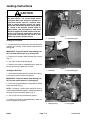
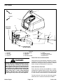
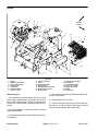
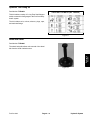
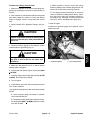
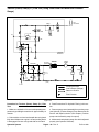
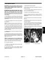
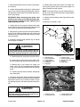
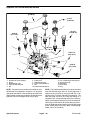
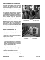
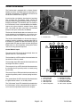
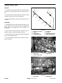
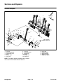
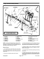
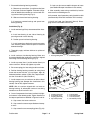
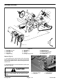
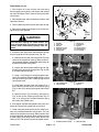
Installation (Fig. 8)
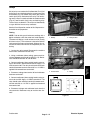
B. Wrap hourmeter wire around spark plug wire and
secure with cable tie.
1. Locate machine on a level surface with key removed
from the ignition switch. Chock wheels to keep the machine from moving.
2. Make sure that all parts removed from the engine
during maintenance or rebuilding are reinstalled to the
engine.
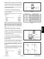
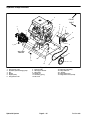
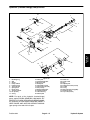
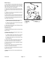
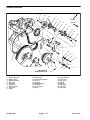
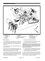
3. If electric clutch and hydraulic pump drive pulley
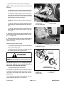
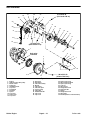
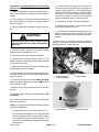
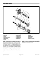
were removed from engine crankshaft (Fig. 11):
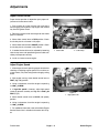
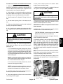
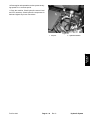
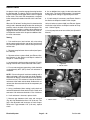
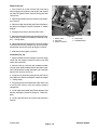
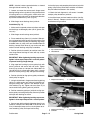
C. Position negative battery cable and wire harness
ground wire to the front corner of engine base (Fig.
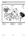
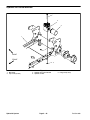
10). Place starwasher between engine and wire connectors and secure with flange head screw.
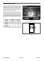
D. Plug machine harness connector to electric
clutch.
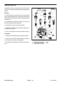
E. Connect red wire and positive battery cable to the
starter motor solenoid stud (Fig. 9).
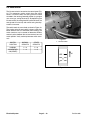
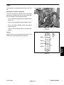
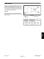
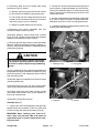
A. Apply anti–seize lubricant to crankshaft.
B. Install hydraulic pump drive pulley with the hub
away from engine.
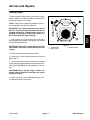
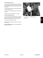
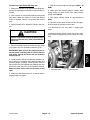
C. Slide clutch onto crankshaft and secure to crankshaft with screw and hardened washer. Hold hardened washer with pliers to prevent crankshaft from
turning and torque screw from 50 to 55 ft–lb (67.9 to
74.6 N–m).
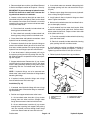
7. After engine installation, verify pulley alignment
across engine and hydraulic pump pulley faces with a
straight edge. If necessary, loosen two (2) set screws on
hydraulic pump pulley and adjust location of pulley. Retighten pulley set screws after adjustment.
8. Install hydraulic pump drive belt (see Pump Drive
Belt in the Service and Repairs section of Chapter 4 –
Hydraulic System).
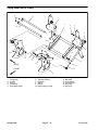
4. If removed, install belt tensioner components to engine assembly (see Belt Tensioners in this section).
9. Adjust hydraulic pump drive belt tension (see Operator’s Manual).
5. Reinstall engine to machine.
10.Install primary drive belt (coring head) (see Primary
Drive Belt in the Service and Repairs section of Chapter
7 – Coring Head).
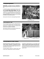
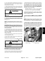
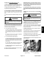
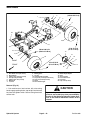
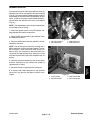
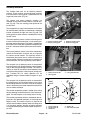
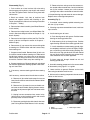
A. Connect a hoist or chain fall to lift tabs located on
each of the cylinder heads.
11. Remove plug installed in fuel hose during disassembly. Connect fuel hose to the fuel filter and secure with
hose clamp.
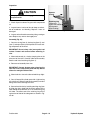
CAUTION
One person should operate lift or hoist while
another person guides the engine to the machine.
12.Install exhaust system (see Exhaust System Installation in this section).
13.Check engine oil level (see Operator’s Manual).
IMPORTANT: Make sure not to damage the engine,
fuel hoses, hydraulic lines, electrical harness or
other parts while installing the engine.
14.Check all wires, control cables and hoses to make
sure that they are not contacted by rotating or moving
parts.
B. Reinstall engine to the machine. Make sure fastener holes of the engine are aligned with the holes in
the machine frame.
15.Connect positive (+) and then negative (–) battery
cables at the battery.
C. Secure engine to the frame with four (4) cap
screws and flange nuts. The front two (2) cap screws
should be positioned down through engine and
frame. The rear two (2) cap screws should be up
through frame and engine.
16.Install pump belt cover to machine (see Operator’s
Manual).
17.Open fuel shut–off valve under the fuel tank.
18.Return coring head service latch to stored position
before using machine.
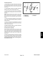
6. Reconnect electrical connections to engine:
A. Plug engine wire harness connector into machine
harness connector.
Kohler Engine
Page 3 – 14
ProCore 648