1
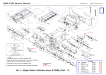
AS900 PRESSURE SEALER
Service Manual
SECTION 1
Installation
Instructions
Page 1 - 1
ISSUE 1
APR 2003
AS900 PRESSURE SEALER
Service Manual
SAFETY NOTES
Warning! Do not work inside the machine unless you are
a trained mechanic or electrician. Stop the machine, and
disconnect the power cord before you do any work
inside the machine. Only a trained electrician should
work with the electrical parts! A voltage of 120 Volts
may be present inside this machine. The power source
can produce enough voltage and current to be very
dangerous!
Warning! This machine is equipped with a three-pronged
plug. One of the prongs on the plug provides a safety
grounding feature. Be sure the plug is always connected
to a properly wired three-prong outlet. Do not use a
two-prong adapter without grounding the machine
properly. Never remove the third prong from the plug.
The safety grounding feature provides extra protection in
the event of an electrical problem. The apparatus must
be earthed.
As the colours of the wires may not correspond with the
colored markings identifying the terminals in your plug,
proceed as follows:
The wire which is colored GREEN and YELLOW must
be connected to the terminal in the plug which is marked
by the letter E or by the safety earth symbol
or colored GREEN or GREEN and YELLOW.
The wire which is colored BLUE must be connected to
the terminal which is marked with the letter N or colored
BLACK.
The wire which is colored BROWN must be connected
to the terminal which is marked with the letter L or
colored RED.
Warning! The mains input supply is fused on both live
and neutral sides. Service personnel should be aware that
a mains voltage can exist even if no lighted neon shows.
Warning! Most of the moving parts are protected by
covers. Don’t operate the machine unless all of the
covers are in place. The covers on the top of the unit
include safety interlock switches. If either cover is raised,
contd.
Page 1 - 2
ISSUE 1
APR 2003
AS900 PRESSURE SEALER
Service Manual
the switch will stop the machine from running. Don’t try
to bypass the interlocks, and don’t use the machine if the
interlocks are not working.
Warning! Don’t wear any loose clothing when you are
working near the machine. If a bit of clothing becomes
caught in one of the moving parts, you may be pulled into
the machine very quickly. This force can be surprisingly
powerful - you may not be able to resist it. Take care
with neckties, sashes, long sleeves, or any other loose
clothing. Dangling jewelry can also present a hazard.
Remove any of these items of loosely-fitting clothing, or
tie the loose sections out of the way so they can’t be
caught by the machine. Long hair can also be dangerous
when working near this type of machine. If you have long
hair, tie it back or tuck it under a hat. Be especially
careful around the folding rolls near the center of the
machine.
Caution!
If a jam occurs, the machine should stop
by itself. Use the jog buttons to move the rollers
forwards or backwards so you can pull out the jammed
forms.
Caution! Keep the machine clean. Wipe off the
outside of the cabinet from time to time to keep the
paper dust from collecting. If you notice that paper dust
is collecting inside the machine, lift the covers and
vacuum it out.
Caution! Keep the work area around the machine
clean. Don’t allow paper trim and waste to pile up. If the
work area includes a lot of loose paper scraps, an
operator may slip and fall.
NOTE: IN THE EVENT OF ANY EMERGENCY, OR TO
STOP THE MACHINE FOR ANY OTHER REASON,
PRESS THE RED EMERGENCY STOP KNOB ADJACENT
TO THE CONTROL PANEL
ISSUE 1
APR 2003
Page 1 - 3
AS900 PRESSURE SEALER
Service Manual
INSTALLATION INSTRUCTIONS FOR
AS900 PRESSURE SEALER
ITEMS SUPPLIED:
1.
2.
3.
4.
5.
Infeed Tray
High Capacity Conveyor
Power Cord
Roller Cleaning Kit
Plastic bag containing:
4 off M5 x 10 Socket Cap head screws E2516A
4 off M5 washers E4012A
2 off M4 x 8 Cross head screws E2624A
2 off M4 x 6 Pozi Countersunk screws E2563A
1.
Unbolt machine from pallet (retained by 1 bolt at each corner through the pallet
bracket).
2.
Remove 4 pallet brackets from machine stand (retained by 2 screws each, accessed by
opening door of stand). See Fig.1 below.
Bracket Screws
FIG.1
3.
Adjust the height of the High Capacity Conveyor (if fitted) so that the sealed documents feed
smoothly onto it (see Fig. 2 overleaf).
ISSUE 1
APR 2003
Page 1 - 4
Service Manual
AS900 PRESSURE SEALER
Adjust height to
suit outfeed of
Sealer
FIG. 2
Outfeed Stacker
4.
Position the stacker into the machine as shown in Fig. 3 below.
Outfeed end of Sealer
FIG.2
FIG. 3
Page 1 - 5
ISSUE 1
APR 2003
Service Manual
AS900 PRESSURE SEALER
4.
Refit side covers. Assemble infeed tray to machine and retain with 2 Countersunk screws
E2563A & 2 pan head screws E2624A, as shown shown in Fig. 4 below.
Countersunk infeed
tray screws E2563A
FIG. 4
Pan head infeed tray
screws E2624A
5.
Check security of CPU Circuit Board and connectors. Access is gained by removing 2
pan head screws underneath infeed tray and lowering cover.
6.
Plug power cord from Conveyor into mains output socket adjacent to mains switch.
7.
Plug signal lead from Conveyor into socket above mains switch.
8.
Plug power cord into machine input socket on mains switch panel.
9.
The machine is now ready to be powered up.
ISSUE 1
APR 2003
Page 1 - 6