1
ORDER NO. AD9903069S2
Minidisc Deck
SJ-MD100
Colour
(K) ........ Black Type
Areas
(E) ........ Europe.
(EB) ...... Great Britain.
(EG) ...... Germany.
$ This document is supplementary to the
following Service Manual:
Model No.
Area Code
Order No.
SJ-MD100
(E) (EB) (EG)
MB9902001C2
$ Purpose
Supplement for technical information about MD.
$ Contents
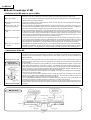
1. Measuring instruments and special tools
Test Disc
O ROM
Part No.: RFKV0006
O ROM
Part No.: RFKV0014
O Extension Cable Kit
Part No.: RFKZJMD100EK
Extension Cable Kit
Laser Power Meter
O Laser Power Meter
Model No.: LE8010
Made by Laser Electric
2. Basic Knowledge of MD
3. Operating Procedures
4. Troubleshooting Guide for MD Servo Circuit
WARNING
This service information is designed for experienced repair technicians only and is not designed for use by the general public. It does not
contain warnings or cautions to advise non-technical individuals of potential dangers in attempting to service a product.
Products powered by electricity should be serviced or repaired only by experienced professional technicians. Any attempt to service or
repair the product or products dealt with in this service information by anyone else could result in serious injury or death.
© 1999 Matsushita Electric Industrial Co., Ltd.
All rights reserved. Unauthorized copying
and distribution is a violation of law.
SJ-MD100
$ Basic Knowledge of MD
T Definition of an MD and the types of MDs
U What is an MD?
Y "MD" stands for "mini disc".
Y Similar to a music CD, an MD is also a small disc capable of recording and playing back digital sound.
U Two types of MDs
Y There are 2 types of MDs, a optical disc for playback-only MD and a magnet optic disc for recordable MD that is
capable of both recording and playback.
U Playback-only MD is same
as a CD.
Y A playback-only MD is merely a smaller-diameter version of a CD. Just like a CD, the signals are read by light
striking pits on the surface of the disc.
U Recordable MD uses
magnet optic recording.
Y With a magnet optic disc MD(Recordable MD) that is capable of both recording and playback, recording is performed by a vertical magnetization system in which a magnetic thin film on the surface of the disc is heated by a
laser beam, and magnetism is applied in accordance with the data (audio signal) being recorded.
U Playback of a Recordable
MD
Y When a recordable MD is played back, a laser beam weaker than that used during recording strikes the disc and
is reflected back, and the reflected light is twisted (polarized) in accordance with whether the magnetized direction
is upward or downward, causing the reflected light to rotate very slightly clockwise or counterclockwise. Those
subtle differences in the reflected light are picked up by two light-receiving elements and detected as either a "1" or
a "0" by reading whether there is electrical current or no electrical current.
U 74-minute recording time
Y If an MD were recorded in the same way as a CD, it would only have about 15 minutes of recording time. However,
by using a new signal compression technology called ATRAC that was specifically developed for MDs, the signals
are compressed to approximately one-fifth, making it possible to record for an extended time of 74 minutes, the
same as with a CD. (Blank MDs are currently marketed in two recording times, 74 minutes and 60 minutes.)
U Can also be used on a
computer.
Y Although MDs were originally developed for use in recording and playing back music, in July 1993 the "MD data"
standard was established. By using an MD data+music player, MDs can be used as external memory storage
media for computers, and a single MD has a storage capacity of 140 MB, equivalent to about 100 floppy discs.
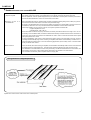
T Construction of an MD
U Construction of an MD
Y The playback-only MD and the recordable MD are exactly identical in size and shape.
Y The figure below is a cross-sectional diagram of an MD disc. The diameter of an MD disc is 6.4 cm, approximately
half that of a CD, and the thickness is 1.2 mm, the same as a CD. Similar to a CD, only one side of an MD disc is
used to store data.
U Materials used in an MD
Y The MD disc is made of polycarbonate, the same material that is used for a CD. Polycarbonate is a type of
engineering plastic that is highly resistant to temperature and humidity, as well as having excellent wear and
impact resistant.
Y A clamping plate is mounted in the center of the MD disc, and when the MD is loaded into a player, a magnet in the
player attracts that metal plate to secure the disc in place. If the MD disc were to be secured by clamping it from
above and below similar to a CD, it would be necessary to have a hole pass through the center of the MD cartridge,
which would reduce the amount of space available for attaching a label. By using this magnetic method of securing
the disc, the entire front side of the MD cartridge can be used as a label area.
Y Because of the metal plate mounted at the center of the MD disc, the center of the cartridge is 2 mm thick, slightly
thicker than the rest of the cartridge.
Y To protect the MD disc from dust, fingerprints, and other things that might hinder the reading of the recorded
signals, the disc is stored inside a cartridge similar to that of a floppy disc. When the MD is loaded into a player, the
shutter on the cartridge is opened and the disc is ready to be played.
Y For a recordable MD, because there is no need for a recording head and it is only necessary for a laser beam to be
directed at the underside of the disc, the shutter is located only on the back of the cartridge.
Y For a playback/record magnet optic disc MD, because it is necessary for the recording head and the laser beam to
be able to access both sides of the disc, the shutter is located on both sides (upper shell and lower shell) of the
cartridge.
Construction of
magnet optic disc
MD disc form
–2–
SJ-MD100
D
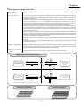
Recording on a magnet optic disc
U Can be recorded and played
back repeatedly.
Y By using a magnet optic disc, digital signals can be recorded and played back over and over again.
U Recording principle
Y To record on a magnet optic disc, a laser beams momentarily heats "pin spots" on the magnetic film on the back of
the disc and a magnetic field is applied from the other side of the disc. Thus, both sides of the disc must be
accessed in order to record.
Y To explain the recording principle, we will assume that the directions of the magnetism on an unrecorded disc are
all facing downward (south-north = "0 0 0 0 ..."). (Actually on an unrecorded disc the directions are random.)
Y Thus, to record the signals "1 0 1 1 0 1 0", the direction of the magnetism at the locations where "1" is to be
recorded must be changed to face upward (north-south). Because the magnetic film is strongly magnetic, once a
downward-facing magnetism is recorded, it is not easy to change it to an upward-facing magnetism.
Y By directing a laser beam at the magnetic film, the temperature of the location that the laser beam strikes rises to
the Curie temperature (recordable MD; about 180pC), eliminating the magnetic force (retention force). (Because
the magnetic film is strongly magnetic, similar to a permanent magnet, once it is magnetized it has a strong
retention force. In order to eliminate that retention force, it is irradiated with a laser beam so that the temperature
rises to the Curie temperature.)
Y After the magnetism of the specific location is eliminated, an external magnetic field with an upward direction
(north-south) is applied, thus changing the direction of the magnetism at that location to face upward (north-south).
Y Conversely, if a downward-facing (south-north) external magnetic field is applied, the direction of the magnetism at
that location is changed to face downward (south-north).
Y Then, when the disc rotates and the location which has been changed to upward-facing magnetism leaves the
laser spot, the temperature of the magnetic film drops, and the upward-facing magnetism recorded at that location
is retained.
Y In this way, digital signals of "1" (upward-facing magnetism) and "0" (downward-facing magnetism) are recorded
on the tracks on the disc.
U Vertical magnetization
system
Y With a conventional magnetic recording tape, the magnetic material is magnetized parallel (horizontal) to the
surface of the tape. A magnet optic disc, however, uses a vertical magnetization system in which the magnetic
poles are recorded perpendicular (vertical) to the disc surface. Because the magnetism is recorded vertically
rather than horizontally, much more data can be recorded in a smaller area.
U Number of recordings
possible
Y A magnet optic disc can be recorded more than 1 million times, so it can virtually last forever.
Magnet optic disc recording principle
A
A
B
Disk rotation direction
Assuming that the directions of
the magnetism on the unrecorded
disc are all facing downward
(they may also all face upward).
wwwwwwwwwwwwwww
S
i
Disk rotation
direction
B
wwwwwwwwwwwwwww
N
Only locations struck by a
powerful laser beam
(reach the Curie temperature)
lose their magnetism
retention force.
i
D
Laser spot
C
Laser spot
Disk rotation direction
Recorded signals.
Directions of magnetism differ
according to whether a "1" or
a "0" digital signal is recorded.
wwwqwtwwqqqwwq
0 0 0 1 0 1 0 0 1 1 1 0 0 1
i
D
Disk rotation
direction
wwwwwt
Heated
wwwwwww
N
Upword : "1"
Downword : "0"
C
An external magnetic
field is applied to the
demagnetized location,
creating upword-facing
magnetism.
External magnetic field is applied.
S
Surface of the disk is a magnetic thin film made of terbium-cobalt alloy.
Horizontal magnetization
Vertical magnetization
–3–
SJ-MD100
D
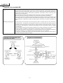
Playback of a recordable MD
U Playback of a recordable
MD
Y Because the signals on a magnet optic disc are recorded vertically as north-south and south-north magnetism, the
north and south magnetic poles appear on the surface of the disc's magnetic film. These signals are played back
utilizing a phenomenon called the "Kerr effect" which occurs when a weak laser beam strikes the magnetic poles.
Y Light has wave vibration directions called "planes of polarization". ("Polarization" refers to a light wave which
vibrates only in a fixed direction.)
Y With normal light, because the wave vibration directions are all mixed, no planes of polarization appear.
Y Because a laser beam is artificially generated light, it is possible to align the planes of polarization.
Y When a laser beam strikes something that has a magnetic field, the direction of the plane of polarization of the
reflected light varies very slightly in accordance with whether the magnetism is north polarity or south polarity.
When playing back a magnet optic disc MD, these slight changes in the direction of the plane of polarization are
read.
U Reading of magnetic signals
Y To further explain the principle used to read the signals recorded on a magnet optic disc, first a laser beam is
directed at the disc. If the direction of the magnetism recorded on the disc is upward (north polarity), the plane of
polarization of the light reflected from the disc rotates very slightly clockwise as a result of the Kerr effect. Conversely,
if the direction of the magnetism is downward (south polarity), the plane of polarization rotates very slightly
counterclockwise.
Y When the reflected laser light is passed through a Wollaston prism, the light is distributed to photo detector 1 if the
direction of rotation is clockwise or to photo detector 2 if the direction of rotation is counterclockwise.
Y The light striking the two light receiving elements is converted into electrical current and a subtraction is performed.
If the result of A-B is plus, a "1" is detected, and if the result of A-B is minus, a "0" is detected.
Y An MD player is compatible with both optical recording and magnetic recording, changing the reading system in
accordance with the type of disc that is loaded.
Changes in the polarization axis
due to the Kerr effect
Playback of recordable MD
–4–
SJ-MD100
D
Rewriting action of a magnet optic disc
U MD rewriting process
Y The signals recorded on an MD are rewritten using a new process called “magnetic field modulation overwriting”*.
Y In this process, a laser beam spot of about 5 mW is focused on the location on the disc to be rewritten, heating that
location to the Curie temperature (180pC) and thus canceling the magnetization.
Y At the same time, current flows to the optical pickup and to the magnetic head opposite it, between the two of which
the disc is held, thus generating a magnetic field.
Y When the disc revolves so the laser spot moves from the location to be rewritten, the temperature drops below the
Curie temperature and the magnetic field generated by the magnetic head re-magnetizes that location.
Y At this time, if the direction of the current flowing to the magnetic head is reversed in accordance with whether the
data being recorded is “1” or “0”, the direction of the magnetic field also changes between north and south, and
accordingly, the direction of the magnetization of the recording film changes between upward-facing and downwardfacing. Thus, it is possible to directly magnetize the recording film on the disc in accordance with the “0” and “1”
digital signals.
U No need for a erasing head
Y Thus, the new recording data is overwritten regardless of the direction of the previously recorded magnetization,
eliminating the need for an erasing head.
Y This process is called “magnetic field modulation overwriting”.
Y Because this “magnetic field modulation overwriting” makes it possible to directly overwrite the new signals on top
of the old signals in a single process, re-recording on a MD is just as easy as with a magnetic tape, making the MD
ideally suited for use in personal audio equipment.
Magnetic field modulation overwriting
*Overwrite means to write new data while erasing the old data.
–5–
SJ-MD100
D
Random access on a recordable MD
U Random access on a
playback-only MD
Y With a disc, high-speed random access is possible, something which is not possible with a tape.
Y The optical pickup moves quickly in the radial direction, thus directly accessing the start of each track.
Y With an optical disc, which is capable of playback only, the addresses in the TOC (table of contents) in the lead-in
area are all read beforehand in order to access the start of each track.
U Random access on a
recordable MD
Y With a recordable MD, which is capable of both recording and playback, blank guide grooves, called “pre-grooves”,
are formed around the entire surface of the disc at the production stage.
Y As shown in the illustration below, the pre-grooves wobble very slightly in a regular pattern, and that curve is finemodulated (at intervals of 13.3 ms) to record beforehand the addresses of the continuous time data.
Y Technically speaking, the pre-grooves in the disc is not perfect spiral but is wobble with :
– a typical amplitude of 30 nm.
– a spatial period of 54 to 64 ¨m.
When this wobble is locked to a frequency of 22.05 kHz, the velocity of the disc should be in the range of 1.2 to 1.4 m/s.
Y In this way, even if the MD is blank, because the addresses are already recorded around the entire circumference
of the disc, when the MD is recorded, those addresses are read in order to control the movement of the optical
pickup and perform CLV control.
Y To record immediately, quick access is first performed to quickly search for an blank area on the disc, and then
recording will automatically begin. When recording is completed, that address is automatically recorded in the UTOC (user table of contents) area, so it can be read during playback for quick and easy access. This also makes
it easy to edit the track number.
U User TOC area
Y Thus, with an MD, when the recording is completed, the track data is automatically written in the U-TOC area at the
innermost part of the magnetooptic disc. The data is then read during playback for quick and easy access.
Y The addresses for the start locations of each track (track mark), and also the addresses for the end locations, are
all recorded in the U-TOC, so when editing a track all that has to be rewritten is the area address.
Y This is similar to the directory that a computer writes on a floppy disk.
Pre-grooves on a magnet optic disc
*Spindle servo control means control of the disc’s rotation speed.
–6–
SJ-MD100
D
ATRAC signal compression technology
U What does the word ATRAC
mean?
Y “ATRAC” (adaptive transform acoustic coding) is the name given to the signal compression technology that is one
of the most important technologies used in the MD system. The principles of this technology are extremely complex,
so here we will only explain the basic concept.
Y Simply speaking, utilizing the characteristics of the human auditory sense, the sounds that cannot be heard by the
human ear are eliminated so that only the sounds that can be heard remain, thus reducing the amount of data that
must be recorded. This principle is similar to the PASC signal compression that is used for digital compact discs.
U Why is signal compression
necessary?
Y The amount of data that can be recorded per second (the bit rate) is 16 bits x 44,100 x 2 channels = 1,411,200 bits
per second, or approximately 1.4 megabits per second (1 megabit = 1,000 kilobits = 1 million bits).
Y However, because the diameter of an MD is only about one-half that of a CD, it only has a capacity of about 160
megabytes. In order to record the same 74 minutes of data as a CD, the bit rate of 1.4 megabits per second must
be compressed to one-fifth. “ATRAC” is the signal compression technology that was developed in order to do that.
(Signal compression is rather like the technology for orange juice concentrate, in which the best part of the fresh
orange is concentrated for easy transportation and then reconstituted with water before drinking.)
U Basic concept of ATRAC
Y The basic concept of ATRAC utilizes the characteristics of the human auditory sense. The frequency spectrum
that cannot be heard by the human ear (Fig. B) and the frequency spectrum that cannot be heard because it is
masked by high-level sounds (Fig. C) are cut, and the bit rate is compressed by appropriately arranging the bits,
thus making it possible to fit all of the necessary data within the capacity of the disc.
YTechnically speaking, the analog signals are converted to 44.1-kHz 16-bit digital signals, and these signals are then
processed by the ATRAC encoder. Using a maximum time of 11.6 ms as a single unit, the encoder converts the
digital waveforms within each single unit into about 500 different frequency spectra and then analyzes the strength
level of each frequency. Then, as shown in the figures below, utilizing the two principles of the “threshold of
audibility” and the “masking effect”, only the signals actually heard by the human ear are selected and compressed
to one-fifth the original volume.
YThis complex process is performed by an LSI chip called the ATRAC.
Threshold of audibility
Signals below the threshold
of audibility are eliminated
Masking by high-level sounds
Fig.A
Fig.B
Fig.C
–7–
SJ-MD100
D
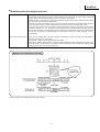
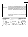
Composition of an MD system
U Development of 6 LSIs
Y The figure below shows the composition of an MD system. An MD system uses six LSIs that were specifically
developed for MD. The following is a description of the functions of those six LSIs.
A RF amplifier
Y This LSI controls the laser and performs the detection processing of the servo signals and of the audio signals from
the disc needed to correct the position of the laser spot.
B Servo control circuit
Y This LSI receives the laser spot position correction signals from the RF amplifier and controls the focus servo that
ensures that the laser spot is correctly focused on the disc surface and the tracking servo that controls the disc
rotation direction to ensure that the pits on the disc surface are traced correctly.
C Address decoder
Y This LSI demodulates the address signals that are recorded in the pre-group on a playback/record magnetooptic
disc MD. In addition to reading the absolute addresses, the address decoder also functions to control the rotation
speed so that the servo signal is obtained at a constant linear speed at the location being read.
D EFM and ACIRC encoder/
decoder
Y This is the main signal processing LSI. EFM is a circuit which converts 8-bit digital signals into the 14-bit format
recorded on the disc. It also performs signal processing for error correction, changing the interleaving format in
order to use the ideal algorithm for MD. In addition, this LSI also performs other tasks such as encoding during
recording and decoding during playback.
E Anti-vibration memory
controller
F Audio signal compression
encoder/decoder
Y This memory controller provides a "shock-proof" memory.
U New generation LSIs
Y New genaration LSIs developed for higher performance of MD system.
There are reduced to three LSIs.
1. RF amplifire
2. 4 ch driver (servo control)
3. Signal processor
Y This LSI performs the signal processing for the ATRAC compression technology that was specifically developed
for MD.
Block Diagram for playback/record MD circuit
–8–
SJ-MD100
$Operating Procedures
Play
P1.
To read the signals recorded on the disc, the laser beam emitted by the laser diode (LD) strikes the disc and is reflected back and
detected by the photodetector (PD).
T For a pre-mastered disc, similar to a CD, the signals are recorded as pits on the surface of the disc, and the signals are
detected by the amount of light reflected when the laser beams strikes the pits.
T For a recordable disc, the signals are recorded by magnetizing the magnetic film on the surface of the disc and there is no
variation in the amount of light that is reflected, so the signals are detected using the shifting of the polarization of the
reflected light due to the Kerr effect*1.
P2. The detected signals are input to pins 38 and 39 of the RF IC (IC1), where they are amplified and then output from pin 32.
T By observing the input signals (between pins 38 and 39) and the output signals (pin 32) on an oscilloscope, it is possible to
check the eye pattern.
P3. Error correction of the amplified signals is performed by the MD LSI (IC3: MN66616) using EFM demodulation and ACIRC*2 and
the signals are stored in the DRAM (IC72: MNV4400). At this time, the cycle of the signals is adjusted by the LSI's clock in order
to eliminate any jitter that might result from irregular revolution of the disc.
P4. The signals are sequentially taken from the DRAM (IC72) and sent back to the MD LSI (IC3), where they are ATRAC*3-decoded
and then output from pin 64.
All of the above steps 1 through 4 are processed on the MD servo PCB, and all of the signals are digital.
P5. The digital signals output from the MD LSI are input to pin 13 of the A/D-D/A converter (IC601: AK4520) via the interface IC
(IC401: TC74HCT7007; input: pin 3; output: pin 4), where they are converted to analog signals and then output from pins 26 (left
channel) and 27 (right channel).
P6. The analog-converted signals are output to LINE OUT via the buffer amp (IC711: BA4560; input: pins 5 (left channel) and 3 (right
channel); output: pins 7 (left channel) and 1 (right channel)). At the same time, they are also output to the headphone amp
(IC801: M5218; input: pins 5 (left channel) and 3 (right channel); output: pins 7 (left channel) and 1 (right channel)).
T The MD servo PCB operates at Vcc = 3.3 V, and the main PCB operates at Vcc = 5 V. For that reason, the exchange of
signals between the two PCBs is performed via an interface IC (during playback: IC401 (TC74HCT7007); during recording:
IC402 (TC74HCT4050)).
T The exchange of signals between the DRAM and the MD LSI is performed using four data lines (pins 1, 2, 24, and 25 of the
DRAM and pins 43, 44, 45, and 46 of the MD LSI).
Record
R1. The analog signals input from LINE IN pass through the REC LEVEL VR and are input to pins 5 (left channel) and 3 (right
channel) of the A/D-D/Aconverter (IC601) via the buffer amp (IC751: BA4560; input: pins 5 (left channel) and 3 (right channel);
output: pins 7 (left channel) and 1 (right channel)).
R2. The analog signals input to the A/D-D/A converter (IC601) are converted to digital signals with a sampling frequency of fs = 44.1
kHz and then output from pin 14 to pin 65 of the MD LSI (IC3) via the interface IC (IC402: TC74HCT4050 ; input: pin 3; output: pin
4).
R3. The signals input from OPTICAL IN are input to pins 70 and 71 of the MD LSI (IC3) via the interface IC (IC401; input: pin 9; output:
pin 8).
R4. The signals input to pins 70 and 71 of the MD LSI (IC3) are converted to a sampling frequency of fs = 44.1 kHz by an fs converter
inside the LSI. If the signals are already fs = 44.1 kHz, they bypass the fs converter.
R5. The signals converted to fs = 44.1 kHz or the signals input to pin 65 are ATRAC-encoded and stored in the DRAM (IC72).
R6. The signals are sequentially taken from the DRAM (IC72) and sent theback to the MD LSI (IC3), where they are ACIRC-processed
and EFM-modulated and then output from pin 73 to the magnetic head.
R7. The magnetic disc records the signals onto the disc by magnetizing the magnetic film on the surface of the disc. During recording
the laser diode emits its laser beam in order to raise the temperature to the Curie temperature*4 that is required to magnetize the
magnetic film. For this reason, the optical power of the laser diode is higher during recording than during playback.
T Although the disc revolves at a speed fast enough to write the signals without compression, the recording signals are
compressed in order to reduce the data volume. As a result, the signals are written intermittently rather than continuously
(the recording signals are intermittently sent to the magnetic head).
Control
C1. Performs the necessary controls for each operation during playback and recording and for writing of the UTOC*5 at the end of
recording.
T The information written in the UTOC includes the recorded track numbers and their addresses, text data, etc.
C2. Performs the necessary displays of the text data recorded on the disc and for each operation.
The system is designed for integrated operation, so that the system control IC (IC10) on the MD servo PCB and the system
control IC (IC901) for the component system mutually exchange data (communicating).
Clock
T The controls of the playback signal, recording signals, and of the 4-channel driver IC (IC1: AN8772) all function using the clock
on the MD LSI as the master clock.
T The A/D-D/A converter (IC601) functions by using the clock signal of the MD LSI as the master clock and frequency-sampling
that signal 384 times via the clock generator (IC501: TC9246).
–9–
SJ-MD100
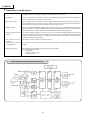
Block Diagram
DRAM(4Mbit)
IC72 MNV4400
Magnetic
head
1
Magnetic head
Drive Q10,11
Spindle
motor
0.45V
P-P
38
Optical
pickup
39
0.5¨s. 0.1V/DIV.
43
44
45
46
RF IC
IC1 AN8772
32
MD LSI
IC3 MN66616
EFM
mod/demo
97
ATRAC encoder /
decoder
Servo signal processor
4ch driver IC
IC2 AN8814
70
69
Loading drive
IC92 LB1830
Loading motor
25
0.9V
P-P
0.5¨s. 50mV/DIV.
Traverse
motor
24
Clock
16.9334MHz
73
DISC
2
65
64
71
System control
IC10
MN101D03D
Detection SW
3.2V
3.2V
0.5¨s. 1V/DIV.
Clock
10.02MHz
0V
0V
T .=. 11¨s.
2
FL display
System control
IC901
M30218
Operation SW
3
8
Interface IC402
TC74HC4050
3
Interface
IC401
TC74HTC7007
3.2V
0V
Clock
10MHz
4
9
0.2¨s. 2V/DIV.
4.8V
T .=. 0.34¨s.
OPTIAL OUT
0V
4.8V
0V
0.2¨s. 2V/DIV.
OPTIAL IN
14
13
5
Buffer AMP
IC751 BA4560
LINE IN
20bit AD /DA converter
IC601 AK4520
Clock
generator
IC501
TC9246
3
6.2V
P-P
LINE OUT
3.2V
P-P
1kHz, 0dB
1kHz, 0dB
Buffer AMP
IC711 BA4560
Head Phone AMP
IC801 M5218
H.P. OUT
170mV
P-P
1kHz, 0dB
VOLUME CENTER
Play signal
REC signal
Clock line
Control line
*1 Kerr effect
A phenomenon in which the polarization plane of laser light reflected from a material shifts in one of two directions
depending upon its “plus” or “minus” magnetic polarization.
*2 ACIRC
Add on interleave CIRC
The aim of Add-on interleave is to improve the resistivity in CD-ROM decoder from the burst error on the disc.
*3 ATRAC
Adaptive Transform Acoustic Cording
The digital data compressing system developed for MiniDisc in which audio signals can be reproduced with only about
1/5 th in the data normally required for high fidelity reproduction
*4 Curie temperature
The temperature at which magnetism of a specific material dissipates. This temperature varies according to the material.
*5 UTOC
User Table Of Contents
Found only on recordable MiniDiscs, this area contains subdata (track number, etc.) which can be rewritten by the user.
– 10 –
SJ-MD100
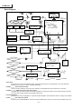
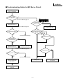
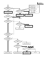
$Troubleshooting Guide for MD Servo Circuit
Switch power ON
with no MD loaded.
Does player
enter self-check
mode? *1
NO
CN4
O 5V S 5V T 3.3V
U 5V [ 3.3V
*1 : See Srevice Manual page 35.
YES
Is CN4 power
supply line OK?
Set to read power
adjustment mode. *2
YES
*2 : See Srevice Manual page 69.
Is read power output?
Check power supply
circuit on main unit.
Is oscillation
signal output from IC10
pin 33?
NO
1
YES
NO
YES
NO
10.02MHz
IC10 pin 33
(Continued on next page.)
NO
Is IC10 pin 21 "H"?
Can read
power be set to 600¨W
or lower using
VR1?
NO
YES
YES
Set to write power
adjustment mode. *3
Faulty optical pickup
*3 : See Srevice Manual page 69.
Is CN4 pin 14 "H"?
Is write power output?
YES
NO
NO
YES
2
(Continued on next page.)
Adjust write power and
check ROM data laser
power and RAM data
laser power.
Faulty IC10
To "ROM/RAM Operation"
(page ?)
– 11 –
Check reset circuit
on main unit.
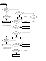
SJ-MD100
1
Is output
voltage of IC1 pin 37
(TP35) approx.
1.3 V *1
NO
YES
Is voltage
of IC1 pin 36
2.6 V? *1
NO
YES
Is voltage
on both sides of R5
at least 0.025 V?
NO
Faulty IC9
Faulty IC1
YES
NO
Is voltage
of IC9 pin 3
2.6 V?
YES
3.3V
0V
Is there
output from IC3
pin 92?
Faulty optical pickup
NO
Faulty IC3
YES
*1: See Service Manual page 27
for measurements of IC1.
Is voltage of
IC1 pin 2 (left side of R8)
approx. 1.8 V?
*1
NO
Faulty IC1
YES
Is voltage
on both sides of R5
at least 0 V?
NO
Faulty optical pickup
YES
2
Faulty Q1
Is current
flowing equal to at
least 1.2 times value
indicated on pick
FPC? *2
YES
NO
3.3V
0V
Faulty optical pickup
*2: Indicated value:
Current equal to that on both
sides of R5 divided by 1 ≠
Is output of
IC3 pin 92 OK?
NO
Faulty IC3
YES
Is voltage of
IC1 pin 2 (left side of R8)
approx. 1.9 V?
*1
NO
YES
Faulty optical pickup
– 12 –
Faulty IC1
Faulty L5
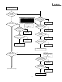
SJ-MD100
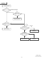
ROM/RAM Operation
5
Can ROM
disc be inserted
correctly?
NO
YES
H = 3.3V
L = 0V
IC10
e LOAD OPEN SW0 (S3)
t LOAD PLAY SW2 (S5)
y LOAD PLAY/REC SW3 (S6)
q DISC-IN
NO
Is disc turning?
IC3 pin 21
Disc tray
OPEN
L
H
H
H
STOP/PLAY
H
H
L
L
REC
H
L
H
L
YES
NO
Faulty loading
TRG S7
Voltage alternates above
and below VREF (1.65 V).
Is output of
IC10 pins 13, 15, 17,
and 18 OK?
YES
Does output
of IC3 pin 21 alternate
above and below VREF
(1.65 V)?
Does CN4
pin 18 change from
"H" to "L" when disc
is inserted?
NO
NO
YES
Faulty S3, S4,
S5, and S6
YES
Faulty IC3
Is voltage
output between IC2
pins 17 and 18?
Is voltage
of IC10 pins 8
and 9 OK?
NO
NO
YES
Faulty IC10
YES
Faulty IC2
Is voltage
output from IC92
pins 2 and 4?
Faulty spindle motor
NO
YES
Faulty IC92
Faulty loading motor
Does optical
pickup move up
and down?
IC3 pin 18
NO
Voltage alternates above
and below VREF (1.65 V).
YES
Does output
of IC3 pin 18 alternate
above and below
VREF (1.65 V)?
NO
YES
Faulty IC3
Is voltage
output between IC2
pins 13 and 14?
3
(Continued on next page.)
NO
YES
Faulty IC2
Faulty optical pickup
– 13 –
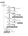
SJ-MD100
3
Is TOC read
and disc data
displayed?
YES
NO
Is there
output from IC1
pins 11 (TP55) and
16 (TP57)? *1
NO
*1: See Service Manual page 27
for measurements of IC1.
YES
Can
waveform of IC1
NO
pin 11 be adjusted so that
it is approx. symmetrical
with a level of
*1
1.5 Vp-p?
Faulty IC1 or
optical pickup
YES
Is RF
waveform output from
IC1 pin 32 (TP52)?
*1
NO
Is voltage
output from IC1
pins 38 (TP44) and
39 (TP37)?
*1
YES
NO
YES
IC1 pin 29
(TP148 or IC3 pin 87)
Faulty optical pickup
Faulty IC1
2.6V
0V
Is there
output from IC1
pin 29 (TP148 or
IC3 pin 87)?
*1
NO
Is voltage
output from IC3
pin 96?
YES
Is RF signal stable?
YES
NO
Faulty IC1
YES
Are
communications
between IC3 and
IC72 OK?
NO
YES
Faulty IC72
Communications error
Does IC10
pin 13 change from
"H" to "L"?
NO
YES
Faulty IC10
4
NO
Faulty S4
(Continued on next page.)
– 14 –
Faulty IC3
SJ-MD100
4
Is playback
possible?
Is playback sound
OK?
61
16.9344MHz
62
10.9344MHz
NO
3.3V
64
0V
Is output of
IC3 pins 61 ~ 65 OK
during playback?
YES
Press eject key
and remove ROM disc.
63
NO
3.3V
65
–
YES
Faulty IC3
Faulty audio circuit
Can RAM disc
be inserted?
NO
5
(To page 10)
YES
Is UTOC
read and disc data
displayed?
NO
YES
After TOC is read,
does traverse move
to UTOC?
NO
See "Traverse Operation"
(next page).
YES
Faulty IC1
Play track
1 of a previously
recorded MD.
Is playback sound
OK?
NO
YES
Insert
a recordable MD.
Is recording
possible?
YES
NO
Is shape
of magnetic head
OK?
NO
Faulty magnetic head
YES
Is there
output from CN8
TP110 and
TP111?
NO
3.3V
0V
YES
Is output
of IC3 pin 73 OK?
NO
YES
Operation complete.
Faulty magnetic
head circuit
Faulty magnetic head
– 15 –
Faulty IC3
SJ-MD100
Traverse Operation
Traverse operation
Remains at outer track.
Remains at inner track.
Is IC10 pin 12
approx. 0 V?
NO
YES
Faulty (shorted) traverse
detection switch S8
Is IC10 pin 12
approx. 3.3 V?
NO
1.65V
or
YES
Faulty traverse
detection switch S8
Is output of
IC3 pin 20 OK?
NO
YES
Faulty IC3
Is voltage
output between IC2
pins 15 and 16?
NO
YES
Faulty traverse motor
Faulty IC2
Printed in Japan
F990406500MT/KH(D)
– 16 –