1
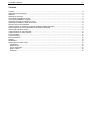
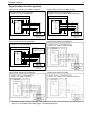
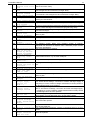
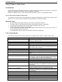
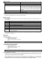
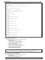
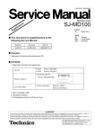
FLASHER 5
Programming tool for
serial in circuit programming
of microcontrollers
with on-chip flash
Software version 1.96
Hardware rev. 3
Manual rev. 4
www.segger.com
A product of SEGGER Microcontroller GmbH & Co. KG
FLASHER 5 Manual
2
Content
Content ....................................................................................................................................................................2
Applicable microcontrollers......................................................................................................................................3
Features...................................................................................................................................................................3
Working environment...............................................................................................................................................3
Connecting FLASHER to the PC .............................................................................................................................4
Using the FLASHER PC program............................................................................................................................4
Using the serial link to program in circuit .................................................................................................................6
Operating FLASHER in stand-alone mode..............................................................................................................6
Remote control of FLASHER 5................................................................................................................................6
Target interface for M16C/62, M16C26P, M16C/80, M32C and R32C ...................................................................7
Serial programming, technical details for M16C/62 or M16C/80 .............................................................................8
Serial target interface circuitry .................................................................................................................................8
Target interface for ST9 Controller ..........................................................................................................................9
Target interface for other systems .........................................................................................................................10
Error messages .....................................................................................................................................................11
Trouble shooting ....................................................................................................................................................13
Known limitations ...................................................................................................................................................13
Support ..................................................................................................................................................................13
Registration............................................................................................................................................................13
Using Flasher in batch mode .................................................................................................................................14
Introduction.........................................................................................................................................................14
General rules......................................................................................................................................................14
List of commands ...............................................................................................................................................14
Return values .....................................................................................................................................................15
Examples ...........................................................................................................................................................15
FLASHER 5 Manual
3
Applicable microcontrollers
Serial mode:
M16C/1N series
M16C/26 series
M16C/20 series
M16C/24 series
M16C/26; M16C26A series
M16C/28; M16C28B series
M16C/29 series
M16C/62 series
M16C/62P series
M16C/64 series
M16C/65 series
M16C/6S series
M16C/6V series
M16C/80 series
M32C/83; M32C/84; M32C/85; M32C/86; M32C/88; M32C/95 series
R8C/14; R8C/15; R8C/18; R8C/19; R8C/22; R8C/23; R8C/24; R8C/25; R8C/26; R8C/27; R8C/28;
R8C/29; R8C/2C; R8C/2D series
R32C series
M38 series
M79 series
ST9 series
For detailed information on supported flash chips please check www.segger.com/flashmcus.htm
Features
•
•
•
•
•
•
•
•
Easy to use windows program
Serial in target programming supported
Programming / Clearing / Verifying / Read back supported; High speed programming
User or boot area selectable (read only in serial mode)
2MByte FLASH to store target program
Can be used in a production environment
PC Program for batch mode processing, allowing usage in automated test systems.
Remote control functions for automated testers
Working environment
General
Flasher has been designed for use in a lab only.
Host System
IBM PC/AT or compatible. CPU: 486 (or better) with at least 8Mb of RAM, running Windows 95 / 98 / 2000
or NT. It needs to have an RS232 interface available for communication with FLASHER.
Power supply
Flasher requires 8 - 24V DC, min. 40mA. You may use the power supply which comes with the tool. Flasher
is protected against polarity reversion on the supply input. Please avoid excess voltage.
Please note: For targets requiring external programming voltage of 12V, the minimum supply voltage is
15V. A 9V battery can be used for single voltage CPUs such as Renesas M16C/62 and M16C/80 groups.
In serial programming mode FLASHER can be supplied from target, if target is operated from 5V and single
voltage target processor is used.
Installing FLASHER PC-software
The PC software FLASHER.EXE is distributed on the accommodating 3.5“ floppy disk or CD; the latest version can be downloaded from our website: http://www.segger.com. In order to use the software, simply copy
it onto your hard drive and start the executable which will guide you through the installation process.
FLASHER 5 Manual
4
Connecting FLASHER to the PC
2
3
2
3
5
5
D-Sub 9, female
D-Sub 9, female
PC <-> FLASHER interface cable
A standard serial interface cable (null modem) can be used to connect FLASHER to the PC. The pin assignment of the 9 pin SUB-D male RS-232 interface connector is as follows:
Pin no. Signal
Function
Host-Signal
2
RxD
Serial async. data input
Serial data output (TxD)
3
TxD
Serial async. data output
Serial data input (RxD)
5
GND
Signal ground
Signal ground
Getting started:
1. Connect FLASHER to a PC running Windows 95/98/2000 or NT using the NULL-modem cable and run
the FLASHER software FLASHER.EXE
2. Connect FLASHER to the power supply.
3. Set up the device via Options|Device menu of PC program.
4. For in-circuit programming: Connect FLASHER to target system via customized interface cable.
Using the FLASHER PC program
General
Flasher comes with an easy to use Windows program. It allows reading of program files in motorola or intel hex format.
The following is a screenshot of
FLASHER.EXE with loaded target program
Communication between PC and FLASHER
Make sure the power supply is connected (one of FLASHERs LEDs should be illuminated) and FLASHER
is connected to your PC with a NULL-modem cable as supplied. If the PC-program displays anything other
than "No communication" under flasher status, the communication between Flasher and your PC is functioning.
First time setup of FLASHER
When using Flasher for the first time, please select the menu point Options|Device. You will see the following dialog box:
First carefully select the correct target device.
A false selection may damage your target!
Then select the chip area you would like to
access, the sectors of the on chip-flash and
the interface you would like to use. The parallel
interface requires a parallel programming
socket; the serial interface requires a cable to
connect FLASHER to your target.
Choose one of the following options:
Start/Endbank to select adjacent banks.
Individual banks to select individual non adjacent banks.
For targets running at low frequencies, it may
be necessary to set the speed option to Slow.
Now you should be able to blank check, clear, program, verify or read the target chip in serial mode (if your
target is properly connected to FLASHER). The first time you program or verify, the PC downloads your target program to FLASHER, where it is stored in the on board RAM chip for programming or verification. The
PC-Program stores all setup information in the registry; when you start the program the next time, it will
start with the same settings.
FLASHER 5 Manual
5
Programming / clearing / verifying / blank check
Select one of the commands
in the TARGET menu to
start the operation. Note that
some of the menu points
may be grayed if you have
no connection to the target
or no file loaded.
A modal dialog box will
indicate the status and
progress of the operation; the operation can
be canceled hitting the
CANCEL button.
Setup
The operating mode of FLASHER may be changed using the
setup dialog from the Options menu.
Power up mode, Power down mode and Reset mode should
not be changed for normal operation. Setting of Power down
mode has no effect on FLASHER 4.
You may change the reset active and reset inactive time, if
required by your target hardware.
You may select reset output mode as Push-Pull output or
Open Drain.
All setup settings are stored permanently in FLASHER after
pressing ‘Save setup’ button.
Additional options
The Filling & Misc. Options from the Options menu may be altered if required.
Normally there is no need to change any of these settings
Improper setting of fill byte may lock your target CPU!
When programming blank (virgin) CPUs ‘Automatic clear before
program’ is not required, so this feature can be disabled to
speed up programming procedure.
Detailed errorlevel on return option may be used to return a
detailed errorlevel to the calling program when Flasher is used
in batchmode.
ID check
When programming Renesas CPUs in serial mode (in target),
an identification of upto 15 bytes has to be supplied. If the
target MCUs user program area is blank, this ID-value does not
matter. However, after programming, these values need to be
set correctly, because otherwise FLASHER will be unable to
communicate with the target CPU. These ID-values can be set
using the menu point Options|Passcode. With a standard program, these values should be 0, as the high bytes of the interrupt vectors which are used to store the values are usually 0.
For more detailed information, please consult the Renesas
users manual. The menu point "Edit | Copy passcode into
loaded file" can be used to copy these ID bytes into your application program.
Problems with ID check
You should act carefully when programming ID bytes. If you do not know the ID-value programmed into a
target chip, there is no way to erase, read or reprogram the chip in-circuit later. We recommend not to use
this feature during the development process.
FLASHER 5 Manual
6
Using the serial link to program in circuit
FLASHER can be used for in circuit programming
of supported CPUs, which incorporate built in
firmware for serial update of user flash. The target
system has to be designed to support this mode of
operation. Refer to target specific connection diagrams or Users manuals of your target CPU.
Basic configuration for serial programming
RS232
Standard
Nul-Modem
cable
FLASHER
Clock
synchrounous
serial
Customer
cable
Target system
with
FLASH MCU
Operating FLASHER in stand-alone mode
After download the target program and all settings are stored in FLASHER 5s on board FLASH memory
and remain valid until new settings or data are sent to FLASHER.
Any number of microcontrollers may now be programmed by FLASHER (one at a time) without the need of
a host PC, by simply pressing the start button. FLASHER will use the settings which have been made in the
PC-program. This includes the selection of target address range as well as any options. Whether the target
CPU will be erased before programming depends on setting of option “Automatic clear before program”.
Progress and result of the operation is indicated by FLASHERs LEDs:
Status of LED
GREEN, flashing
GREEN
RED
Meaning
Erasing / Programming / Verifying operation in progress
Programming operation successful
Programming operation failed
Remote control of FLASHER 5
FLASHER 5 can be remote controlled by automated testers without the need of a connection to PC and
Flashers PC program. Therefore FLASHER 5 is equipped with additional hardware control functions, which
are connected to the SUBD9 male connector, normally used as RS232 interface to PC.
The following diagram shows the internal remote control circuitry of FLASHER:
Pin No.
1
Function
START
4
BUSY
7
OK
5
GND
Description
A positive pulse of any voltage between 5 and 30V with duration of min. 30 ms starts
“Auto” function (Clear / Program / Verify) on falling edge of pulse. Whether Clear is
executed depends on Options | Filling & misc. | Automatic clear before program.
As soon as Auto-Function is started, BUSY becomes active, which means that transistor is switched OFF.
This output reflects result of last action. It is valid after BUSY turned back to passive
state. The output transistor is switched ON to reflect OK state.
Common Signal ground
FLASHER 5 Manual
7
Target interface for M16C/62, M16C26P, M16C/80, M32C and R32C
The clocked synchronous interface from Flasher to target system is built with a 10 pin dual in line pin connector,(pin1 is marked at the connector) at the front of FLASHER. Function depends on selected target.
Pin no.
1
2
3
4
5
6
7
8
9
10
Signal
VCCS
BUSY
SCLK
RxD
CE
EPM
GND
RESET
CNVss
TxD
Function for M16C/62, M16C/80
Positive supply voltage of target
Target CPU Busy signal output
Target CPU Serial clock (input)
Target CPU Serial data input
Chip enable signal of target CPU
EPM signal of target CPU
Common signal ground
RESET signal of target system
Target CPU CNVss signal
Target CPU Serial data output
Specification / remarks
Input 3.0 .. 5.5V to supply the interface
FLASHER Input with Pull-Up to internal 3.3V
FLASHER Output, CMOS driver via 220 Ohms
FLASHER Output, CMOS driver via 220 Ohms
FLASHER Input / Output
FLASHER Input / Output
--FLASHER Output, CMOS driver via 220 Ohms
FLASHER analog Output
FLASHER Input / Output
If RESET of target system is driven by a reset circuitry with active high driver, RESET output of FLASHER
must not be connected directly to CPU reset of target. For M16C/62 or M16C/80 targets you do not have to
connect RESET to FLASHER; you can always manually reset your target system after connecting
FLASHER.
Target system interface for M16C/62 or M16C/80
Connection Diagram for serial programming:
FLASHER <===> target CPU M16C/62 or M16C/80 groups
Target System
VCC
M16C
NMI
VCCS
BUSY
SCLK
RxD
CE
EPM
GND
RESET
CNVss
TxD
VCC
RTS1
CLK1
RxD1
CE (P50)
EPM (P55)
GND
Reset
CNVss
TxD1
* R>= 1kOhm
9
10
1
2
FLASHER
Target interface
(front view)
Caution:
Before connecting the target with Flasher, ensure that there is NO difference in the ground potential
between Flasher and target.
When the Flasher is connected to a PC via RS232C cable, ensure that the PC and the target operate on
the same ground potential.
Connect the ground lines from PC and your target before connecting the Flasher to the target.
If a ground potential difference between Flasher and target exists, the Flasher may be damaged.
FLASHER 5 Manual
8
Serial programming, technical details for M16C/62 or M16C/80
Serial programming uses a clock synchronous interface. 8 bits of data (1 byte) is transferred at a time. The
commands which are used are described in the Renesas manuals. In general, the sequence is as follows:
FLASHER resets the target system by pulling the /Reset line low for a period of time which is set as Reset
active time in Options|Setup dialog of PC program.
FLASHER waits for the Reset inactive time, nominal 500 ms, (tRD) in order to allow the target system to recover from reset. This time can also be set in Options|Setup dialog via PC program.
FLASHER checks the BUSY line. If it is active (high level) FLASHER stops with error message
40: Target chip says "BUSY" because it can not communicate with the target system
FLASHER outputs one clock (clock changes from high to low and back). BUSY should now be active (high).
If it is not active, FLASHER stops with error message 41: Target chip: Busy does not react
FLASHER outputs 7 more data bits ( 7 clock cycles) and waits for BUSY to go low.
More data bytes are output (or read) the same way.
tRD
tRL
Reset
BUSY
tRL : nominal 20 ms
tRD : nominal 500 ms
tb
tdhh
SCLK
TxD
tdsu
high
RxD
Serial target interface circuitry
tdhl
tCH
tCL
The reset active time (tRL) and
reset inactive (eg reset delay)
time (tRD) can be set in Options|Setup dialog if required.
FLASHER 5 Manual
9
Target interface for ST9 Controller
The clocked synchronous interface from Flasher to target system is built with a 10 pin dual in line pin connector,(pin1 is marked at the connector) at the front of FLASHER. Function depends on selected target.
Pin no.
1
2
3
4
5
6
7
8
9
10
Signal
VCCS
Function for ST9F120
Positive supply voltage of target
RxCLK
SIN0
TxCLK
SOUT0
GND
RESET
Target CPU Serial clock input
Target CPU Serial data input
Target CPU Serial clock output
Target CPU Serial data output
Common signal ground
RESET signal of target system
Specification / remarks
Input 3.0 .. 5.5V to supply the interface
Not used for ST9, leave open
FLASHER Output
FLASHER Output
FLASHER Input with 47k Pull-Up
FLASHER Input with 1.2k Pull-Down
--FLASHER Output
Not used for ST9, leave open
Not used for ST9, leave open
If RESET of target system is driven by a reset circuitry with active high driver, RESET output of FLASHER
must not be connected directly to CPU reset of target.
When using Pull-Ups in Your target system, the Pull-Up at SOUT0 must not be smaller than 47kOhm.
Target system interface for ST92F120 or ST92F150
Caution:
Before connecting the target with Flasher, ensure that there is NO difference in the ground potential
between Flasher and target.
When the Flasher is connected to a PC via RS232C cable, ensure that the PC and the target operate on
the same ground potential.
Connect the ground lines from PC and your target before connecting the Flasher to the target.
If a ground potential difference between Flasher and target exists, the Flasher may be damaged.
FLASHER 5 Manual
10
Target interface for other systems
Target system interface for M38xx groups
Target system interface for M30201 or M30218
Connection Diagram for serial programming:
FLASHER <===> target CPU M30201 type
Connection Diagram for serial programming:
FLASHER <===> target CPU M3803 / M3804 / M3886 groups
Target System
Target System
VCC
VCC
M30201
M38xx
VCCS
BUSY
SCLK
RxD
VCC
CLKS
CLK0
RxD0
NMI
RD
GND
RESET
CNVss
TxD
GND
Reset
CNVss
TxD0
VCCS
BUSY
SCLK
VCC
SRDY1 (P47)
SCLK1 (P46)
OE
(P37)
GND
RESET
VPP (12V)
SDA
GND
Reset
CNVss
RxD
(P44)
9
10
* R>= 1kOhm
1
2
9
10
* R>= 1kOhm
FLASHER
1
2
FLASHER
Target interface connector
(front view)
Target interface connector
(front view)
Target system interface for M38C2xx
Target system interface for M37906F8
Connection Diagram for serial programming:
FLASHER <===> target CPU M37906F8
Target System
Remarks on MD0:
If low signal is required, MCU pin may be
connected to GND, connection to Flasher
is not neccessary.
If high signal is required, MCU pin must not
be fixed to VCC. Then a pull-up resistor
has to be used.
VCC
M37906
VCC
BUSY
SCLK
VCCS
BUSY
SCLK
(P26)
(P24)
MD0
MD0
GND
Reset
MD1
SDA
GND
RESET
MD1
SDA
(P25)
9
10
* R>= 1kOhm
1
2
FLASHER
Target interface connector
(front view)
Target system interface for M 38507F8
Target system interface for R8C
More target specific interface connection examples may be shown in the online help of the Flasher PC program or on our website at http://www.segger.com/flashertarget5.html.
FLASHER 5 Manual
11
Error messages
The following error messages can occur during operation of FLASHER (shown in red on your PC) or returned as errorlevel when operated from batch file and “Detailed errorlevel on return” option is set.
Code
1
2
3
4
5
6
7
21
30
31
Error message
Erase failed
Write failed
Verify failed
Blank check failed
Flash write/erase
timed out
Can not write into
this memory area
Canceled
Version read failure: Rx line problem ?
No ID
ID mismatch
32
40
ID mismatch
Target chip says
"BUSY"
41
Target chip: Busy
does not react
42
Target chip says
BUSY
43
Timeout of target
55
CRC check in programmer failed.
Internal Vcc drop
during operation
DAC for Vpp not
calibrated
Unsupported interface, check device
setting
Unsupported command
56
58
60
61
62
63
70
71
72
73
No target data, please
download
FLASHER lost Setup
Illegal start byte
received
No start byte received
No acknowledge received
Target: communication timed out
Meaning / remedy
Erase operation has failed
Write operation has failed
Verification failed. Loaded Program and contents of the flash-memory
are not identical.
Chip is not blank
Could not write into flash memory, the max. waiting time has been
exceeded
In serial mode, the boot area of Renesas CPUs can be read out, but
can not be written to.
Last operation has been canceled by user.
In serial mode, FLASHER reads out the version of Renesas target
CPUs bootloader. If this is not the right format (VER….), a read line
failure is most likely.
Renesas target CPU has no valid ID (This error should not occur)
Renesas bootloader (target CPU) requires the correct ID. Without it,
you will be unable to access, read out, clear, or program the contents
of the flash memory. The requested ID depends on ID previously written into the target CPU. For more information, please refer to the section “ID code check function” of the CPUs users manual.
Same as Error 31
Renesas target chip has BUSY signal high (active). Most likely CPU did
not enter bootmode. Check all signals to target. Refer to CPUs users
manual about conditions to enter bootmode.
Renesas target CPU should set BUSY after receiving the first bit or
byte (depending on CPU). Some possible reasons for this error:
a) RESET is not released
b) Target did not enter the serial I/O mode because conditions to enter
bootmode are not met. Check RESET, EPM, CE, CNVSS)
c) No clock (check with oscilloscope)
Renesas target chip keep its Busy signal set (active) during communication. This inhibits communication between FLASHER and target.
Some possible reasons:
a) RESET is not released
b) Target did not enter the serial I/O mode because the signals applied
when RESET is released are not correct (EPM, CE, CNVSS)
c) No clock (check with oscilloscope)
Target command Clear, Program or Verify could not be finished within
expected time. Please report this error.
Integrity of target data held in FLASHERs internal memory is lost.
Download new data to FLASHER.
A voltage drop on Flashers internal supply was detected. Internal data
may be damaged.
FLASHER lost calibration data for Vpp generation circuit. Please return
FLASHER to factory, as calibration can not be done by user.
FLASHER is requested to access a target CPU that is not supported by
Flasher. Normally this fault should not occur. Ensure that Flasher PC
software version fits to Flasher firmware version
FLASHER received a command that is not supported. Ensure that
Flasher PC software version fits to Flasher firmware version.
FLASHER 5 never received valid data for target, therefore target can
not be programmed. Download target data.
Setup data for Flasher invalid. Please run Option | Setup. and Option |
Device.
ST9 CPU did not send correct byte after reset release. Please check
target connection.
ST9 target CPU did not send a Byte after reset release. Most likely ST9
CPU did not enter boot mode. Please check target connection.
ST9 CPU did not send back acknowledge of command sent to RAMCode.
ST9 target CPU did not send back data within expected time.
FLASHER 5 Manual
74 RAMCode does not
respond after start
byte
75 RAMCode does not
work
76 RAMCode does not
respond command
202 Blank check failed
203 Verify failed
204 Clear target failed
205 Target auto function failed
206 Programming target
failed
207 Reading target
failed
210 Could not open
source file
211 Invalid Parameter.
212 Invalid parameter
count.
213 Invalid command
syntax.
214 Firmware mismatch
215 The selected target
chip is not supported by the connected programmer.
216 Session mismatch.
Resetting connection
217 Flasher refuses
connection..
218 None of the selected com ports is
available.
219 Error in HEX file
220 Invalid file extension, use .MOT,
.HEX or .BIN
221 Invalid file name
222 Error in Protocol
Manager
223 VCCS > VCCSmax
(Target supply
voltage too
high...)
224 VCCS < VCCSmin
(Target supply
voltage too low
...)
225 Flasher Input voltage too low
226 Assertion
227 Invalid default
program settings
found. Please setup
device.
228 Flasher not ready !
229 Invalid commandline
option
230 Flasher defect !!!
Target interface
does not work.
12
During download of RAMCode to ST9 CPU, target did not respond.
Check connection. Retry.
After download of RAMCode to ST9 target, RAMCode did not respond.
Check target CPU and connection to target. Retry.
After download of RAMCode to ST9 target, RAMCode did not respond
to commands. Check target CPU and connection to target. Retry.
Target CPU is not blank.
Verification failed. Loaded Program and contents of target CPUs flashmemory are not identical.
Erase operation has failed.
Any error occurred during “Auto” function (Clear / Program / Verify)
An error occurred during programming of target. If target was not blank
before, ensure that target is erased before programming. Retry.
An error occurred during reading of target. Retry operation. Check
connection to target.
The source file given as parameter could not be opened. Check file
name or path.
Invalid command line parameter found.
Check parameter. Refer to command description.
Check parameter. Refer to command description.
PC software version differs from firmware version of Flasher.
Download new firmware via Options menu. Otherwise proper function
can not be guaranteed.
Check and setup device settings.
It seemed, that Flasher was disconnected during communication between Flasher and PC. Try an other COM port.
Did you select a chip which is not supported ? Check device settings.
PC program could not open selected COM-Port. Select an other COM
port.
The HEX file for target could not be read. Check file format.
You tried to open or save a Hex file with unsupported file extension.
You tried to Open or merge a file that could not be found. Check file
name or path.
PC program internal error. Restart program.
Supply voltage of target exceeds max value defined for selected device. Check device settings, connection to Flasher and target supply. If
everything is correct, Flashers voltage measurement circuitry seems to
be damaged and has to be repaired.
Supply voltage of target is lower than min value defined for selected
device. Check device settings, connection to Flasher and target supply.
If everything is correct, Flashers voltage measurement circuitry seems
to be damaged and has to be repaired.
Flashers supply voltage is lower than required to generate programming voltage of connected target CPU. Check supply voltage.
PC program internal error. Restart and try again.
Your registry contained invalid data about Flasher PC program. Setup
device and other options.
Setup data could not be sent to Flasher. Is a Flasher connected to your
PC? Check COM port.
Your command line parameter contains a command which is not supported.
Target interface of FLASHER not found during initialization. Flasher
has to be repaired.
FLASHER 5 Manual
13
Trouble shooting
Proper operation of FLASHER in serial mode depends on your target system. If you have any trouble operating FLASHER in serial mode, please:
a) Check your target hardware,
b) Check the connecting cable,
c) Use an oscilloscope to check the state of all signals on the target connector, especially to check if the
target CPU is RESET properly and the target CPUs BUSY signal works properly.
Known limitations
Serial mode
Older versions of the Renesas M16C/62 bootloader sometimes do not start after RESET. If you experience
problems in communicating with the target system, power down the target system, power it up and try
again.
Support
For support questions, please consult our website at www.segger.com. If this does not answer your questions, please send an email to [email protected].
Registration
Registered customers will receive the free updates they are entitled to. Please register online:
www.segger.com/register.html. The information will be stored in a data base and will be treated confidentially.
FLASHER 5 Manual
14
Using Flasher in batch mode
Introduction
Flasher.exe supports command line options to enable automated programming of targets. This document
describes the supported commands and their respective parameters.
Flasher PC software version 1.72b or above replaces FlasherPro, which is not delivered anymore.
How to start Flasher program in batch mode
To use Flasher in batch mode, just call Flasher.exe directly from DOS-Box or start any batch file which calls
Flasher.exe, To start any action, parameter may be passed as command line options.
General rules
•
•
•
•
•
•
The first parameter specified must be the file to load, if download is required.
The return code is 0 if all operations have been executed successfully, !=0 otherwise.
All commands are identical to the corresponding commands in the menu bar.
All commands are processed from left to right.
If “-exit” is specified as the last command, the program will terminate as soon as any error occurs or after all commands have been executed.
If one parameter contains a space use quotation marks for this parameter.
List of commands
The following commands are currently supported as parameter when Flasher is called in batch mode:
Command
-download
-checkblank
-verify
-clear
-clearchip
-programverify
-program
-readback
-start
-com<PORT>
-saveas<FILENAME.EXT>[,FIRST-LAST]
-merge<FILENAME.EXT>
-delrange<FIRST-LAST>
-relocate<OFFSET>
-selbanks<START,END>
-selmultiple<BANK1, BANK2 … BANKn>
-seldevice<DEVICENAME>
-password<LENGTH,ID1,ID2,...,IDn>
-setFILL<xx>
-openfile<FILENAME.EXT>
-setACBP
-setCOD
-setDE
-setDNVBP
Description
Downloads the loaded hex file into Flashers memory without
starting any additional action.
Checks if target is blank
Verifies loaded data with contents of target
Clears target area, selected memory banks
Clears entire chip. Clearing the entire chip might not be implemented for all devices. Then the command behaves the
same as the clear command.
Programs & verifies target
Programs loaded data into target
Reads target area into PC
Starts application program (serial mode only, only Flasher
MV3)
Sets COM-port of PC(1..4).
Saves the file currently in PC memory. The extension needs
to be “MOT”, “HEX” or “BIN” and determines the filetype.
The optional range is used for files in BIN-format.
Merge specified file to current data
Deletes the specified range of data
Relocates current data by offset
Sets the numbers of start and end bank. The numbers have
to be the same as in the selection box shown under Options/Device.
Selects individual banks. The numbers have to be the same
as in the selection box shown under Options/Device.
Selects the desired device. The name of the device has to
be exactly the same as in the selection box shown under
Options/Device.
Sets the ID-bytes
Sets the fill byte, the parameter is a two digit hex number.
opens a HEX file
Sets option 'Automatic clear before program'.
Sets option 'Clear on demand'.
Sets option 'Detailed errorlevel on return'.
Sets option 'Do not verify blank pages'.
FLASHER 5 Manual
-clearACBP
-clearCOD
-clearDE
-clearDNVBP
-index<X>
-exit
-help
-?
15
Clears option 'Automatic clear before program'.
Clears option 'Clear on demand'.
Clears option 'Detailed errorlevel on return'.
Clears option 'Do not verify blank pages'.
Allows selection of an individual setup data set for Flasher.
This is useful when multiple Flasher should be handled concurrently with one PC. After setting up all options together
with the –index command, further calls of Flasher with the
same index command will restore all previous settings for
that index.
Finish execution after performing all commands
Displays available commands.
The same as –help
NOTE:
To open a HEX file, place the file name as first parameter just behind the call of Flasher.exe, the openfile
command is not required when only one file should be opened.
Return values
The following return values are sent as errorlevel unless “Options | Filling & misc. | Detailed errorlevel on return” is selected:
Value
2
3
4
5
6
7
8
9
10
>10
Meaning
Target not blank
Verify error, Contents of target data not identical to FLASHERs internal data.
Erase error. Target CPU could not be erased.
Error during Program & Verify function
Eror during programming of target CPU
Error during target readback.
Error during “Start application”.
Timeout error.
HEX file could not be opened.
Corresponds to error number which would normally shown on PC screen when program was
used in normal mode.
When “Detailed errorlevel on return” is set as option, the returned value equals to error codes described under chapter “Error messages”.
Examples
Program and verify
In the following example the software
• reads the file TEST.MOT
• tells the Flasher to program and verify,
• exits.
Flasher.exe test.mot -programverify
-exit
Programming using specified com port
In the following example the software
• reads the file TEST.MOT
• sets the COM-port of the PC to Port 2,
• tells the Flasher to program,
• exits.
Flasher.exe test.mot -com2 -program -exit
Usage in production environment
This example shows a batch file that executes a download to the Flasher once. After the first call of Flasher
the batch file runs in a loop that programs the last downloaded file continuously after pressing a key. After
every execution of Flasher the return code is evaluated.
NOTE: Evaluating the return code only works under WindowsNT or Windows2000. If you use Windows9x
Flasher will be started in a new task and you can’t evaluate the return code from the DOS-box from which
you started Flasher, because your DOS-Box will not halt execution until FLASHER finished!
FLASHER 5 Manual
@echo off
rem The first call of Flasher loads the the HEX file
Flasher test.mot -program -verify -exit
goto checkerror
rem Loop for repeated programming without download
:loop
pause
Flasher -program -verify -exit
rem Check errorlevel if succeed
:checkerror
if errorlevel 1 goto ERROR_%errorlevel%
echo Operation successfully finished
goto loop
rem handle errors
:ERROR_1
echo Undefined error
goto end
:ERROR_2
echo ERROR_TARGET_CHECKBLANK
goto end
:ERROR_3
echo ERROR_TARGET_VERIFY
goto end
:ERROR_4
echo ERROR_TARGET_CLEAR
goto end
:ERROR_5
echo ERROR_TARGET_AUTO
goto end
:ERROR_6
echo ERROR_TARGET_PROGRAM
goto end
:ERROR_7
echo ERROR_TARGET_READBACK
goto end
:ERROR_8
echo ERROR_TARGET_STARTAPPLICATION
goto end
:ERROR_9
echo ERROR_TARGET_TIMEOUT
goto end
:ERROR_10
echo ERROR_OPENDOCUMENTFILE
:end
echo Operation canceled
Relocate, delete, merge and save
The following example shows a batch file, where the software
• reads file A.HEX,
• deletes the range 0xFC0000..0xFFFFFF,
• moves the remaining bytes 0x40000 bytes up,
• saves the memory contents as B.MOT,
• reads the file A.HEX again,
• deletes the range 0xC00000..0xCFFFFF,
• moves the remaining bytes 0x340000 bytes down,
• saves the memory contents as C.MOT,
• merges the files B.MOT and C.MOT
• and save the new file as RESULT.BIN.
Flasher A.HEX -delrangeFC0000-FFFFFF -relocate040000 -saveasB.MOT -exit
Flasher A.HEX -delrangeC00000-CFFFFF -relocate340000 -saveasC.MOT -exit
Flasher B.MOT -mergeC.MOT -saveasRESULT.BIN,C00000-CFFFFF -exit
Selecting device and setting ID bytes
The following example shows a batch file, where the software
• selects a device,
• sets the ID bytes to FF,FF,FF,FF,FF,FF,FF
• and reads the contents of the device.
Flasher -seldeviceM30201F6xx -password7,FF,FF,FF,FF,FF,FF,FF -readback
16