1
3460 Grant Drive
●
Lebanon OH, 45036 ●
Toll Free: 800-528-3113
www.fecon.com
BH410-22-REV-A
1/10/2007
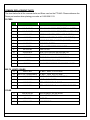
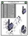
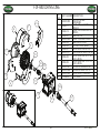
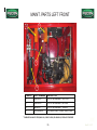
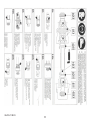
COMMON REPLACEMENT PARTS
The chart below list all the common belts and filters used on the FTX-440. Please reference the
Fecon part number when placing your order at 1-800-528-3113.
FILTERS
ITEM
PART NUMBER
DESCRIPTION
1
440-46-005
2
440-45-021-01
CAB AIR CLEANER FILTER (EXTERNAL SAFETY)
3
440-45-021-02
CAB AIR CLEANER FILTER (EXTERNAL PRIMARY)
4
440-60-006
HYDRAULIC FILTER (OPEN LOOP SUCTION)
5
44-60-006
HYDRAULIC FILTER (CLOSED LOOP RETURN)
6
440-60-010
ELEMENT FILTER 10 MICRON (CHARGE)
7
44-1R-1808
ENGINE OIL FILTER
8
44-1R-0771
FUEL / WATER SEPERATOR FILTER
9
44-1R-0749
FUEL FILTER
10
44-220-8678
SEAL FOR FUEL WATER SEPERATOR
11
51044-01
PRIMARY AIR CLEANER ELEMENT
12
51044-02
SECONDARY AIR CLEANER ELEMENT
13
11783
14
BH203-01
CAB AIR CLEANER FILTER (INSIDE)
FILLER BREATHER FILTER
HYD FILTER ELEMENT, SCHROEDER 100GPM
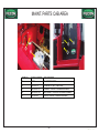
BELTS, LIGHTS, BULBS
11
440-57-053
AC BELT, AX45, 47.2 OUTSIDE
12
44-57-055 (2REQUIRED)
AC BELT, CX90, 94.2 OUTSIDE
13
440-45-006
LIGHT HOUSING, FRONT AND REAR
14
440-45-007
LIGHT HOUSING SIDE
15
440-45-019L
REPLACEMENT BULB, DOME
16
440-45-006L
REPLACEMENT BULB, ALL OUTSIDE FIXTURES
17
440-45-005-04
18
440-56-005
EXHAUST RESONATOR
19
RT440038
MUFFLER
20
660-21-138
RADIATOR CAP
OTHER
BH410-22-REV-A
REPLACEMENT WIPER BLADE
1/10/2007
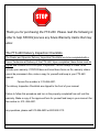
STOP
Thank you for purchasing the FTX-440. Please read the following in
order to help FECON process any future Warranty claims that may
arise:
The FTX-440 Delivery Inspection Checklists
The Dealer and Operator Delivery Inspection Checklists are to be completed with a
Fecon Technician at Delivery of the FTX-440. Upon completion, these forms must be
signed.and returned to FECON prior to operation. Fecons receipt of these forms
activate your warranty. If FECON does not have these forms on file, warranty claims
cannot be processed. Also, make a copy for yourself and keep in your FTX-440
manual.
Fecons Fax number is: 513-696-4431.
The delivery Inspection Checklists are clipped to the front of your manual.
Failure to follow this procedure and turn in the properly completed form will void the
warranty. Make a copy of the approved form for yourself and keep in your manual. Our
fax number is: 513- 696-4431.
Any questions, please call 513-696-4430 or 800-528-3113.
BH410-22-REV-A
1/10/2007
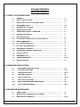
FTX-440 CONTENTS
SECTION 1-SAFETY
1.0 SAFETY IN THE WORK AREA
1.1
GENERAL……………………………………………………………………………….
3
1.2
SAFETY INSTRUCTIONS……………………………………………………………..
3-4
1.3
OPERATIONAL SAFETY/ THE WORK AREA……………………………………..
5
1.4
THE HAZARD ZONE…………………………………………………………………...
5-6
1.5
DANGEROUS LOCATIONS…………………………………………………………..
6-7
1.6
URBAN PRECAUTIONS………………………………………………………………
7
1.7
OPERATIONAL SAFETY / OPERATOR…………………………………………….
8
1.8
HEARING PROTECTION……………………………………………………………...
9
1.9
DUST PROTECTION…………………………………………………………………...
9
1.10
PROTECTION FROM FALLING / FLYING OBJECTS…………………………….
10
1.11
AVOID POWERLINES…………………………………………………………………
10
1.12
P.T.O. DRIVELINE SAFETY…………………………………………………………..
11
1.13
POLICING THE WORK AREA………………………………………………………..
11
1.14
AVOID METAL AND WIRE……………………………………………………………
11
1.15
CAUTION WITH STRINGY VEGETATION………………………………………….
12
1.16
AVOID PLASTICS………………………………………………………………………
12
1.17
EMERGENCY EXIT…………………………………………………………………….
12
1.18
TOWING PROCEDURE……………………………………………………………….
13-14
1.19
FIRE PREVENTION…………………………………………………………………….
15
2.0 OPERATION INSTRUCTIONS
2.1
PRE-OPERATION INSTRUCTIONS……………………………………………….
16
2.2
STARTUP PROCEDURE …………………….…………………………………….
16-23
2.3
IQAN INSTRUCTIONS ……………………………………………………………...
23-27
2.4
CARRIER CONTROLS……………………………………………………………
28
2.5
INITIAL OPERATION……..…………………………………………………………
28-29
2.6
HEAT AND A/C SYSTEM…………………………………………………………...
30
2.6.1
SEAT ADJUSTMENT AND MAINTENANCE ...................................................
30
2.6.2
SHUT DOWN PROCEDURE ……………………………………………………….
30-31
3.0 PREVENTIVE MAINTENANCE
3.1
SAFETY FIRST………………………………………………………………………….
33
3.2
MAINTENANCE ACCESSIBILITY AND PARTS……………………………………
33
3.3
MAINTENANCE SCHEDULE…………………………………………………………
33-36
BH410-22-REV-A
1/10/2007
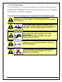
This Safety Alert Symbol identifies important safety
messages on machines safety signs, in manuals or
elsewhere. When you see this symbol, be alert to
the possibility of personal injury or death. Follow
the instructions in the safety message.
This Safety Alert Symbol means:
ATTENTION! BECOME ALERT!
YOUR SAFETY IS INVOLVED!
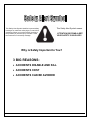
Why is Safety Important to You?
3 BIG REASONS:
• ACCIDENTS DISABLE AND KILL
• ACCIDENTS COST
• ACCIDENTS CAN BE AVOIDED
BH410-22-REV-A
1/10/2007
DO NOT OPERATE OR WORK ON THE FTX-440 WITHOUT READING
AND UNDERSTANDING THIS OPERATION MANUAL.
It is the responsibility of the User / Operator to read and understand this operation and safety manual
along with all other safety documentation provided.
Safety is up to you!
You can prevent serious injury or death
IF THIS MANUAL IS LOST OR IF YOU HAVE ANY QUESTIONS,
CONTACT FECON OR YOUR DEALER BEFORE YOU PROCEED.
FECON, Inc.
3460 Grant Drive
Lebanon, OH. 45036
800-528-3113
BH410-22-REV-A
1/10/2007
SECTION 1: SAFETY
1.1 General
The FTX-440 with the attached Bull Hog 350, is designed to process heavy organic
material such as branches, stumps heavy timber and brushwood. The machine may be
used in forests for land clearing and cultivation.
NOTE: The FTX-440 is only to be used for its designed purpose. Any
modification to the machine will void the Warranty.
Damages due to any misuse of the FTX-440 will void the Warranty.
Consult your State and Local governing bodies for regulations on operating or
transporting organic processing equipment.
DO NOT OPERATE OR WORK ON THE FTX-440 WITHOUT READING AND
UNDERSTANDING THIS OWNERS/INSTRUCTION MANUAL. IF THIS MANUAL IS
LOST OR IF YOU HAVE ANY QUESTIONS, CONTACT FECON OR YOUR DEALER
BEFORE PROCEEDING.
OBEY ALL SAFETY LABELS ON THE FTX-440. THEY ARE PROVIDED FOR YOUR
PROTECTION. IF ANY LABELS ARE REMOVED, DAMAGED OR MADE UNREADABLE
IN ANY WAY, CALL YOUR FECON DEALER FOR A REPLACEMENT AT THE NUMBER
BELOW.
FECON, Inc. 3460 Grant Drive Lebanon, OH 45036
1-800-528-3113
Read and follow these Safety Instructions!
PRIOR TO OPERATION:
• Read the owners manual in its entirety and follow all safety procedures.
• Check all fluid levels in the 440 unit per the owner’s manual.
• Check PTO Gearbox oil level on BH350-PTO mulcher
• Check all grease points per the owner’s manual.
• Check all fasteners on BH350-PTO mulcher for tightness
BH410-22-REV A
3
1/10/2007
1.2 Operational Safety/ The Operator
The FTX-440 is designed to handle the most rugged of forestry applications. It is certified with
the following safety protection systems:
Operator Protective Structure (OPS)
SAE J1084 SEP2002
ISO 8084 2003-05-01
Rollover Protective Structures (ROPS)
ISO 8082 2003
Falling Object Protective Structures (FOPS)
ISO 8083 1989
The FTX-440 Cab is equipped with ½” Marguard Lexan® polycarbonate on all four sides.
Proper maintenance is imperative to the safe operation of the machine; all windows must be
replaced with ½” Lexan® or a polycarbonate equivalent if there are any signs of excessive
scratching, cracks, visible stains, indentations, or any other sign of wear and/or damage.
The FTX-440 is also equipped with a fully adjustable seat and harness system. The seat is
equipped with at electronic seat switch that will deactivate all joystick functions, disable the
PTO output, and apply the parking brake if the operator is not present in the seat.
Along with these safety features incorporated into the FTX-440, it is the operator’s
responsibility to implement and monitor proper safety. Every job and application must be
evaluated on a case by case basis to determine the need for additional safety procedures and
equipment.
PROTECT YOURSELF!!
Wear all the protective clothing and personal safety devices issued to you or called for by
job conditions
You may need:
•
Hard Hat
•
Safety Shoes
•
Safety glasses, goggles or face shield
•
Heavy Gloves
•
Hearing Protection
•
Reflective Clothing
•
Wet Weather Gear
•
Respirator or Filter Mask
•
Wear correct protective gear for the conditions encountered.
BH410-22-REV A
4
1/10/2007
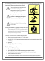
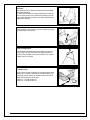
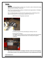
The following precautions must be strictly observed to protect the operator. They may
also apply to others near the work area as well.
The provided hand rails and steps must
be used when mounting and
dismounting the Carrier. Do not get on
or off using any other method.
Keep all surfaces clean and free of
moisture, ice, debris and loose objects.
These can create a “Slip Hazard”
Always wear safety belt when operating
the FTX-440.
Use the grab handles for support if vehicle turns over.
When stopping the FTX-440, the mulcher must be
positioned with rotor at stand still. Always remove
the key when leaving the vehicle.
CAUTION! TAKE THE FOLLOWING PRECAUTIONS:
•
Always keep doors and windows of FTX-440 closed.
•
Use ANSI S3.19-1975 approved hearing protectors with a noise reduction rating (NRR)
of 25dB (A)
•
Ear muffs
•
Ear plugs (disposable or reusable)
Take the following precautions:
•
Do not smoke while re-fueling.
•
Do not add fuel, fluids or make adjustments while engine is running.
•
Ground the fuel funnel or nozzle against the filler neck to prevent sparks.
•
Always replace the fuel tank cap.
•
Clean fuel spills immediately. Discard soiled material following disposal regulations.
BH410-22-REV A
5
1/10/2007
Other Cautions:
•
Avoid running engine in confined spaces. Exhaust fumes are dangerous.
•
Do not remove radiator cap while hot! Pressure will release hot liquid and cause harm.
•
Disconnect battery before performing service to vehicle.
•
Use only approved fluids for maintenance.
•
Discard used fluids following all disposal regulations.
•
No transporting of passengers.
•
Do not operate while under the influence of drugs or alcohol. On prescribed medicines
follow the instruction listed on the medication.
•
Never operate vehicle with the door open.
•
When working on steep slopes, always drive directly straight up or down hill to keep
vehicle from tipping over.
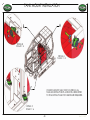
1.3 OPERATIONAL SAFETY/THE WORK AREA
For the sake of this manual, the front of the FTX-440 is the side with the Bull Hog 350
attached. The rear of the Bull Hog has deflection chains. When the Bull Hog is mounted on the
front of the machine, the front of the mulcher is facing the same forward direction.
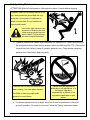
WARNING!
Danger caused by flying debris!
Improper operation and failure to follow safety precautions can result in personal injury
to persons too close to the machine.
Protection from Flying or Falling Objects
As illustrated in Section 1, BE ALERT of the possibility of projectiles exiting the
machine. Falling brush, branches, and trees also present a potential hazard
to the operator.
BH410-22-REV A
6
1/10/2007
CAUTION: DO NOT CROSS WATER DEEPER THAN 4 INCHES OF WATER !!
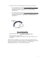
Avoid Power Lines
Serious injury or death can result from contact with electric lines. Never move any part of the
equipment or the tree it’s carrying, closer than 10’ plus twice the line insulator length to an
electric line. Use a signal person to guide operator. Use shrouds or insulators as necessary.
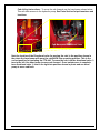
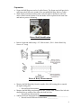
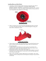
The Hazard Zone
The following diagram illustrates the Hazard Zone. All personnel should
be kept clear of this zone while the Bull Hog is operating.
The shaded area in the Hazard Zone must be considered OFF LIMITS TO ALL
INDIVIDUALS! The operator should follow the following PRECAUTIONS before and
during operation of the Bull Hog.
WARNING!
•
Danger caused by flying debris!
IT IS THE OPERATORS RESPONSIBILITY TO ENSURE THAT NO ONE STANDS IN
THE HAZARD AREA!
•
WARN all persons in the area of the HAZARD ZONE to stay clear of the Zone
•
STAY ALERT for outsiders entering the work area who may not be aware of the
HAZARD ZONE.
•
Land clearing operations generally involve other machinery and people on the
site. MAINTAIN an AWARENESS of all working traffic within 50 yards of the Bull
Hog operation.
NOTE: Improper operation and failure to follow safety precautions can result in
personal injury to persons in the hazard area described below.
BH410-22-REV A
7
1/10/2007
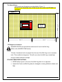
The Hazard Zone:
The hazard zone dimensions are described in Figure 1.1
All personnel should be clear of the hazard zone while the FTX-440 is in
operation.
BH350-PTO
FTX-440
300 FT.
Figure 1.1
Hazard
Zone
300 FT.
300 FT.
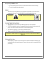
1.5 Dangerous Locations
DANGER EXISTS most prominently behind and in front of the Bull Hog.
(Refer to the HAZARD ZONE above)
REAR:
Chunks of wood and rock can project from the rear of the Bull Hog on non-excavator
units. This condition is dangerous. This will occur when the Bull Hog is raised high
enough to allow material to escape.
FOLLOW THESE PRECAUTIONS:
•
NEVER allow anyone to the rear of the Bull Hog while it is in operation.
•
Inspect the Carrier and Bull Hog daily for damaged or missing deflection chains and
flaps
BH410-22-REV A
8
1/10/2007
Be especially CAREFUL when:
•
The tool is being raised up and out of the material that it has been working.
•
The tool is lowered into new material.
FRONT:
The area in front of the Bull Hog may experience projectiles in less volume when
compared to the rear. Do not stand within the recommended safety zone.
WARNING!
Danger caused by flying debris!
FOLLOW THESE PRECAUTIONS!
•
NEVER allow anyone in front of the Bull Hog while it is under operation.
•
CLOSE the hydraulic trap door (if equipped) while pull-working to better contain all
pieces. This also increases the fineness of the shredded product.
•
(See Bull Hog Operation – Pull-working in BH350 Section).
•
Again, be most CAUTIOUS when lowering or raising the machine.
Remember!! Always observe the hazard zone as shown in the previous diagram
Figure 1.1
Policing the Work Area
Before starting, a visual survey of the area to be worked is helpful in identifying any
undesirable items that may be present. Remove them as much as is practical before
proceeding.
BH410-22-REV A
9
1/10/2007
Avoid Metal and Wire!
Metal tends to break the hammers’ carbide tips. Wire seeks to wrap itself around the
rotor shaft, especially near the bearings. The wire can tighten and squeeze past the
grease seals causing BEARING DAMAGE IF NOT REMOVED.
NOTE: Wire is sometimes attached to large solid objects (such as fence posts) which
can become projectiles. The wire has the capability to sever limbs or even cause death
if an individual is in the Hazard zone! Make sure that HAZARD ZONE is CLEAR and
area has been cleared of all such hazards.
Use Caution with Stringy Vegetation!
Shredding things like Palmetto, Bird of Paradise, and yard waste tied with plastic
causes them to gravitate towards the bearings. The Bull Hog readily handles this
material but the operator should exercise additional caution while working it.
Avoid Plastics!
.. Hoses, bags, tarps and ropes must be removed as soon as they are seen.
.. Mattresses, rugs, clothes, and cloth will plug the machine immediately.
.. Any time is a good time to inspect the rotor for clinging strands.
BH410-22-REV A
10
1/10/2007
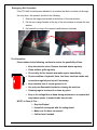
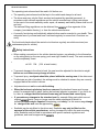
Safety during Maintenance
ATTENTION!! After full load operation, idle engine for about 1 minute before stopping.
Hydraulic leaks are not always visible to the
eye. Wear protective gloves and use eye
protection. Use a piece of cardboard or
wood to locate leak. Do not handle with
unprotected hands!
Fluid under high pressure can
penetrate or lacerate skin and
cause severe injuries that can
lead to death! If oil penetrates
skin seek hospital treatment!
• Hydraulic pressure will remain after unit power has been shut off. Lower the Bull hog to
the rest position and connect locking support rods to the Bull Hog 350 PTO. (This keeps
the push bar from falling in case of hydraulic pressure loss.) Then release remaining
pressure from lines before beginning work.
Liquids must be disposed of
according to all regulations. It is
the owner /operators
responsibility to adhere to the
regulations applicable to their
region.
Fluids will be hot after the machine has
been running. Use care when draining
hot fluids or removing caps under
pressure to avoid burns.
•
If machine requires service or repair in the field it must be positioned on flat even
ground if possible. If it needs to be moved, follow the Towing Instructions below.
BH410-22-REV A
11
1/10/2007
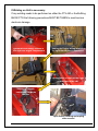
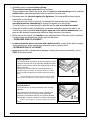
Towing Procedure
Tools required:
Utility knife or equivalent to cut tie wrap
1-1/4” wrench
1-1/16” wrench
The FTX 440 can be towed only a short distance at a very slow speed. The following
procedure is designed to move the carrier a short distance to an alternate transportation
source or to flat level ground where repairs can be made. If the FTX-440 should
become disabled in a situation that requires the tractor be towed, the operator should
follow the following instructions:
STEP 2:
Use the manual
pump to release
brake.
STEP 1:
Cut the tie wrap ;
Rotate valve 45°
clockwise
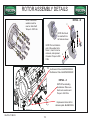
After completing the steps above, the series 90 pumps on the engine will need to be bypassed mechanically. Do this by rotating the bypass hex on both valves (3) three turns
counterclockwise (CCW).This allows fluid to circulate without rotating the pump and prime
mover. See figure below.
BH410-22-REV A
12
1/10/2007
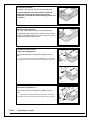
CAUTION: POSSIBLE PUMP AND / OR ENGINE DAMAGE
Bypass valves are intended for moving the carrier a very short
distance at a very slow speed. They are NOT intended as tow
valves.
Two Bypass
valves on each
pump
Place a 1 ¼” wrench on the large bottom hex to hold it
in place. Place a 1-1/16” wrench on the middle hex.
Rotate the middle hex three (3) times counterclockwise
to open the bypass valve. NOTE: DO NOT ROTATE
MORE THAN 3 ½ TIMES. LEAKAGE WILL OCCUR!!
Large
wrench
must not
move
To close the bypass valve after moving to repair area, rotate the middle hex
CLOCKWISE until seated. Torque the middle hex to 30 foot pounds.
Transport on Public Roads
To transport the FTX-440 on public roads it:
• must be transported on a low loader.
• must be secured on the loading floor of the truck trailer.
• All traffic laws in areas transported through must be adhered to.
• Transporting vehicle must be equipped with all safety equipment required
by law. (Brake lights, reflectors etc)
BH410-22-REV A
13
1/10/2007
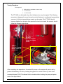
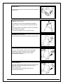
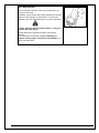
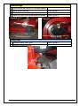
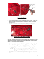
If Welding on Unit is necessary:
If any welding needs to be performed on either the FTX-440 or the BullHog
BH350 PTO the following precautions MUST BE TAKEN to avoid serious
electronic damage.
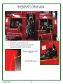
v
Disconnect the battery located in
the right rear engine compartment
Unplug the Engine wiring located in
the right rear engine compartment
Open toolbox located on the right
outside next to the cab.
Unplug all module
connectors inside the
toolbox.
Open screen housing and unplug
video screen.\
BH410-22-REV A
14
1/10/2007
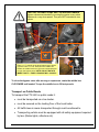
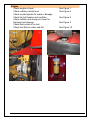
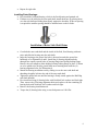
1.7- P.T.O. Driveline Safety
The FTX-440 utilizes a P.T.O Driveline to transfer power to the Bull Hog 350 mulching unit.
The cardan shafts are designed for ease of assembly and maintenance, but most importantly
for safe operation. As with other moving parts:
STAY CLEAR OF THE CARDAN SHAFT AREA WHILE THE CARRIER IS RUNNING!
SHUT OFF TRACTOR AND REMOVE KEY BEFORE PERFORMING
MAINTENANCE ON THE FTX-440. FOLLOW LOCKOUT TAGOUT PROCEDURE
(29 CFR 1910.147)
CAUTION!
DO NOT WEAR LOOSE CLOTHING OR JEWELRY THAT
COULD GET CAUGHT IN DRIVE!! CONTACT WITH ROTATING
EQUIPMENT CAN CAUSE SERIOUS INJURY OR DEATH!!
CAUTION!
CAUTION!
KEEP OPERATORS AND BYSTANDERS AWAY FROM
MOVING PARTS!
CONTACT WITH ROTATING EQUIPMENT CAN CAUSE
SERIOUS INJURY OR DEATH!!
ENSURE THAT ALL GUARDS ARE PROPERLY INSTALLED
BEFORE OPERATING.
CAUTION!
DO NOT STAND ON, STEP OVER OR GO UNDER DRIVELINE!
CONTACT WITH ROTATING EQUIPMENT CAN CAUSE
SERIOUS INJURY OR DEATH!!
CAUTION!
BH410-22-REV A
15
1/10/2007
Emergency Exit Procedure
If the FTX-440 should become disabled in a situation that does not allow exit through
the entry door, the operator should do the following:
1. Remove the hinge pins located at the bottom of the rear window.
2. Pull the two orange handles at the top of the rear window to release the rear
window.
3. Exit carefully moving to the nearest handholds and footholds.
Fire Prevention
Please adhere to the following cautions to reduce the possibility of fires:
•
Keep the machine clean. Remove dust and debris regularly.
•
Clean radiator grills regularly.
•
Check daily for fire hazards and make repairs immediately.
•
Check condition of hydraulic lines, fuel lines, electrical cables and
connectors regularly and repair if necessary.
•
Keep machine free of excess grease or oil.
•
Use only non-flammable liquids for cleaning the machine.
•
Cleaning rags to be stored in a clean dry place.
•
Keep a fire extinguisher at hand during maintenance or repairs that
may induce sparks. (Located inside door of cab)
NOTE: In Case of Fire….
Stop the Engine!
If possible, extinguish with fire extinguisher!
Make sure fire does not spread!
Call for help if needed.
BH410-22-REV A
16
1/10/2007
SECTION 2 - OPERATION INSTRUCTIONS FOR THE FTX-440
• IMPORTANT! READ THESE INSTRUCTIONS BEFORE OPERATING!!
• THE INITIAL HOURS OF PROPER OPERATION CAN CONTRIBUTE GREATLY TO
THE SUCCESSFUL OPERATION AND LONGEVITY OF YOUR MACHINE.
PRE-OPERATION INSPECTION OF THE FTX-440
•
Perform a walk around visual inspection of the FTX-440.
•
Check condition of tracks and exterior.
•
Check oil level of the C13 engine.
•
Check all fluid levels to ensure safe operation of unit.
•
Climb in to the cab using the footholds and handrails to ensure good balance.
2.1- SEAT ADJUSTMENTS AND INSTRUCTIONS
NOTE: FOR SAFETY PURPOSES, THE FTX-440 CAN ONLY BE OPERATED WHILE DRIVER IS IN THE SEAT.
WHEN THE SEAT IS UNOCCUPIED, THE BRAKE IS AUTOMATICALLY SET AND THE MACHINE WILL NOT
MOVE.
Seat Contents:
General instructions ................................................................................................................................................. 17
Safety instructions ...............................................................................................................................................17-18
1 Weight adjustment ........................................................................................................................................... 19
2 Height adjustment ............................................................................................................................................ 19
3 Seat depth adjustment *................................................................................................................................... 19
4 Seat pan angle adjustment * ............................................................................................................................ 19
5 Fore/aft adjustment without control carrier equipment**.................................................................................. 20
6 Fore/aft adjustment with control carrier equipment* ** ................................................................................... 20
7 Control carrier* ** ............................................................................................................................................. 20
8 Headrest* (optional extra) ................................................................................................................................ 21
9 Seat heater * (optional extra) ........................................................................................................................... 21
10 Lumbar support ** ............................................................................................................................................ 21
11 Armrests *.(optional extra) ............................................................................................................................... 22
12 Armrest adjustment *........................................................................................................................................ 22
13 Backrest adjustment......................................................................................................................................... 22
14 Fore/aft isolator ................................................................................................................................................ 22
Maintenance............................................................................................................................................................. 23
* if fitted
**depending on model
BH410-22-REV A
17
1/10/2007
General Instructions
The operating instructions should be read in full before use.
• The operating instructions should be kept in the vehicle and always be at hand.
• The driver seat may only be fitted, serviced and repaired by specialist personnel, in
accordance with national regulations and the vehicle manufacturer’s fitting instructions.
In the event of incorrect assembly and/or repair, all warranty and liability claims shall be null
and void.
or from agencies of the
The national fitting regulations can be obtained from
company (see dealer directory), or from the vehicle manufacturer.
• A correctly functioning and individually adjusted driver seat is essential to your health. Take
adequate care of your seat and have it serviced regularly to ensure that it functions correctly.
The functional checks should be carried out at least as regularly as vehicle services (see
maintenance plan for vehicle).
Safety instructions
• When making connections to the vehicle electrical system, pay attention to the information
on the rating plate (on the rear spring; push seat right forward to read). The seat connection
must be separately fused:
•
-at 24V 10A
(15A at seat heater)
• To prevent damage to the driver’s back, the seat must be adjusted for the driver’s weight
before use and before every change of driver.
• To prevent injury, no objects should be placed within the moving area of the driver seat.
• To eliminate any risk of accident, the settings must be checked to ensure they are correctly
engaged before the vehicle is driven.
•
•
Adjustments must not be made while driving.
When the backrest upholstery has been removed, the backrest frame must be supported, for example held in place, before the backrest adjuster is operated. If you fail to do
so, there is a danger that the backrest frame may jerk forward and cause injury.
•
If you make any changes to the standard seat (for example fitting parts which are not
original
parts) it may no longer meet the safety standards to which it is
tested.Functions may be impaired, threatening your safety. For this reason, any change
in design of the seat must be approved by
.
•
Seatbelts can be retrofitted to the driver seat. Seatbelts may only be fitted on the
approval of the vehicle manufacturer, as they increase the load in the seat mounting
area. Seatbelts must be fitted in accordance with specific national regulations and
guidelines, and must be approved by
.
BH410-22-REV A
18
1/10/2007
• Seatbelts must be fastened before driving.
The seatbelts must be replaced after an accident.
Where seatbelts are fitted to the driver seat, the seat and seat mounting must be checked
additionally by specialist personnel after an accident has occurred.
• Fasteners must be checked regularly for tightness. If the seat wobbles there may be
loose bolts or other faults.
If the seat does not function correctly (for example the seat suspension), contact a
specialist workshop immediately to arrange for repairs to be carried out.
If you fail to do so, your health may be affected and the risk of accident increased.
• Seats with a built-in switch (to deactivate component units when leaving the seat or the
vehicle) may only be installed with the prior approval of the vehicle manufacturer, and
may only be operated together with additional safety devices in the vehicle.
• Before driving the vehicle, the function of any switches fitted in the seat must be checked.
If malfunctions are detected the vehicle must not be driven.
– INCREASED RISK OF ACCIDENT –
• Loads must not be placed on seats with a built-in switch, except for the driver’s weight
during normal use, as the vehicle may otherwise start to move by itself.
- INCREASED RISK OF ACCIDENT •
can provide no guarantee for damage resulting from incorrect assembly, use or
repair of the driver seats.
Weight adjustment
The seat should be adjusted for the driver's weight by briefly
pulling the actuator lever of the automatic weight and height
adjuster (arrow) with the vehicle at a standstill and the driver
sitting on the seat.
The driver must sit absolutely still during adjustment. To
prevent damage to the health, the setting for the driver’s weight
must be checked and adjusted as necessary before the vehicle is
driven.
To prevent damage to the health, the setting for the driver’s weight
must be checked and adjusted as necessary before the vehicle is driven.
Height adjustment
The seat height can be set pneumatically and is infinitely
adjustable.
The seat height can be altered by pulling or pressing the
actuator lever fully out or in (arrow). If the adjustment
reaches the top or bottom end stop, the height is adjusted
automatically in order to guarantee a minimum spring travel.
In order to avoid damage, do not operate compressor for more than
1 minute
BH410-22-REV A
19
1/10/2007
Seat depth adjustment *
The depth of the seat pan can be individually adjusted.
To adjust the depth of the seat cushion, lift the R/H
handle (see arrow). By moving the seat cushion
backwards or forwards the desired seating position can
be reached
Seat pan angle adjustment *
The angle of the seat pan can be individually adjusted.
To adjust the angle of the seat pan, lift the L/H handle (see
arrow). By exerting pressure on or off the seat pan it can be
moved to the desired angle position.
Fore/aft adjustment without
Control carrier equipment **
The fore/aft adjustment is released by lifting the locking
lever.
The locking lever must latch into the desired position. It should not
be possible to move the driver seat into another position when it is locked.
Fore/aft adjustment with
control carrier equipment * **
The fore/aft adjustment is released by lifting the locking
lever.
The locking lever must latch into the desired position. It should not
be possible to move the driver seat into another position when it is locked
* if fitted
**depending on model
BH410-22-REV A
20
1/10/2007
Control carrier *
To improve getting in and out of the seat the left or right box
can be tilt up.
Headrest *(optional extra)
The headrest can be individually adjusted for height by
pulling it upward over the various increments up the end
stop.
By pushing forward or rearward the angle of the headrest
can be adjusted individually.
To remove the headrest, pull it over the end stop.
Seat heater *(optional extra)
The seat heater is turned on by pressing the switch (arrow).
Lumbar support **
The curve of the backrest cushion can be individually
adjusted by pressing the upper and lower switches.
This increases both the seating comfort and the
performance of the driver.
Lumbar support **
By turning the adjustment knob to the left or right, both the
height and curvature of the backrest cushion can be
individually adjusted.
This increases both the seating comfort and the
performance of the driver.
BH410-22-REV A
21
1/10/2007
Armrests *
The armrests can be folded up if required and the height
individually adjusted.
To adjust the armrests for height, separate the round cap
(see arrow) from the cover, loosen the hexagon nut (size
13mm) and adjust the armrest to the desired position and
tighten the nut again.
Armrest adjustment *
The inclination of the armrests can be modified by turning
the adjustment knob (arrow).
Backrest adjustment
The backrest is adjusted using the locking lever (arrow).
The locking lever must latch into the desired position. It
should not be possible to move the backrest into another
position when it is locked.
Fore/aft isolator
Under certain driving conditions (for example with a trailer
attached), it is useful to activate the fore/aft isolator. This
means that shock impacts in the driving direction can be
better absorbed by the driver seat.
Position 1 = fore/aft isolator on
Position 2 = fore/aft isolator off
BH410-22-REV A
22
1/10/2007
SEAT MAINTENANCE
Dirt can impair the function of the seat, so make sure you
keep your seat clean!
Upholstery can be quickly and simply removed from the seat
frame for easy cleaning, or replacement. To remove the
upholstery, turn the clips (arrow) and remove the upholstery.
Caution: take care with the backrest frame - it may jerk
forward and cause injury!
During cleaning the upholstery should not be soaked
through.
Use a standard commercially available upholstery or
plastics cleaning agent. Test first for compatibility on a
small, concealed area.
BH410-22-REV A
23
1/10/2007
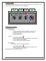
2.2- HVAC Controls
The climate control is designed for the HVAC system installed in the FTX-440 Carrier. The
following figures show the controls for cabin temperature.
Fresh /RC
Selector
Fan Speed
Selector
Re-Circulate
Fresh
Low
Off
Function
Selector
Off
Temp
Adjustor
Heat AC
Med High
Coolest
Warmest
Heating and AC Operation
Windshield Defrosting
For best results:
Rotate temperature adjustor completely clockwise to red.
Rotate the Fresh Air / Re-circulate selector to fresh air.
Set fan to high setting
Open all front vents.
To Heat:
Set function selector to
Rotate the temperature adjustor clockwise to setting desired.
Set Fan speed to setting desired.
Adjust temperature as needed for comfort.
Air Conditioning:
NOTE: Engine must be running to operate AC.
Set function selector to
Rotate the temperature adjustor counter-clockwise to cool.
Set Fan speed to setting desired.
Adjust temperature as needed for comfort.
BH410-22-REV A
24
1/10/2007
2.3- INITIAL OPERATION:
NOTE: On startup allow FTX-440 to idle for at least 1 minute before attempting any maneuvering or Bull Hog testing
•
Before moving the FTX-440, test all functions including lift, tilt and rear door.
•
Refer to Right Joystick Diagram for Bull-Hog controls.
•
Immediately report any suspected problems to Fecon Inc. at 1-800-528-3113
CARRIER CONTROLS- Left Joystick
FORWARD
AHEAD
AHEAD
BH-350-
BH-350-
FTX-440
DOOR
CLOSE
BH-350-
FTX-440
TRACK
SPEED
CONTROL
FTX-440
INCREASE
RANGE
HIGH/LOW
DECREASE
VERTICAL
AXLE LEFT
VERTICAL
AXLE
RIGHT
DOOR
OPEN
BH-350-
FTX-440
REVERSE
LEFT JOYSTICK- DRIVING CRAWLER
BH410-22-REV A
25
1/10/2007
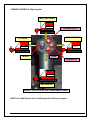
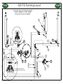
CARRIER CONTROLS- Right Joystick
MULCHER DOWN
FTX-440
PUSHBAR DOWN
TILT FORWARD
TILT BACK
OUT
FTX-440
IN
FTX-440
HORN
WINCH
PUSHBAR UP
FTX-440
MULCHER UP
RIGHT JOYSTICK- LIFT AND MULCHER
NOTE: For IQAN Control refer to IQAN operation Section of manual
BH410-22-REV A
26
1/10/2007
SECTION 3- PREVENTIVE MAINTENANCE FOR FTX-440
Proper preventive maintenance will help ensure that the FTX-440 will perform to its full capabilities and eliminate
unnecessary breakdowns due to neglect. The manufacturers warranty is conditional upon following all
maintenance recommendations.
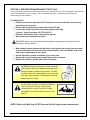
3.1 Safety First!
Perform maintenance only after the FTX-440 carrier has been shut-off and all moving
parts have come to a stop.
Ensure that the ignition key is removed from the FTX-440.
Lock-out the carrier to prevent it from being started following
Lockout / Tagout Procedure (29 CFR 1910.147).
Dismantle the machine only on flat and firm ground.
Wear protective equipment at all times.
WARNING! Never work on machinery with the engine running unless instructed so by the
operating or service manual.
When making engine adjustments that require the engine to be running you must work
as a two man team with clear method of communication. One in the drivers seat as the
other makes adjustments to the engine.
Ensure that there is proper ventilation in your work area.
Always wipe up all excess grease and oil when work is complete.
Replace all protective guards when work is complete.
WARNING! Hydraulic systems are under extremely
high pressure! Use thick cardboard and wear thick
gloves to inspect for leaks in the system. The leak
could be hard to see and possibly could cut through
skin due to high pressure! The cardboard will show
leaks quickly and safely.
DO NOT WEAR LOOSE CLOTHING OR JEWELRY
THAT COULD GET CAUGHT IN ROTATING
COMPONENTS!! CONTACT WITH ROTATING
EQUIPMENT CAN CAUSE SERIOUS INJURY OR
DEATH!!
NOTE: Refer to the Bull Hog 350 PTO manual for Bull Hog parts and maintenance.
BH410-22-REV A
27
1/10/2007
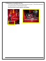
3.2 Maintenance Accessibility and Parts
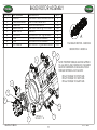
To move the cab forward use the hand pump shown in figure 3. This will allow access to
the hydraulic gearbox located beneath the cab.
See Parts Section for part numbers and locations.
Hand pump
Hand pump directional valves
BH410-22-REV A
28
1/10/2007
3.3 - MAINTENANCE SCHEDULE
NOTE: A LIST OF REPLACEMENT FILTERS FOR THE FTX-440 IS PROVIDED ON THE BACK OF THE COVER ON THIS
MANUAL. THE FOLLOWING LIST CONTAINS RECOMMENDED FLUID INFORMATION FOR THE FTX-440.
Fluid Type
Engine Oil
Hydraulic Oil
Diesel Fuel
Fluid Coupling
Final Drives
Bull Hog Gear Box
PTO Gear Box
Fluid Description
15W-40
AW46
No. 1-D or No. 2-D
ISO 32
SHC 629
75w90 Synthetic
75w90 Synthetic
Fill Qty.
10.5
65
150
5
5-6
8-10
5.3
Fill Units
gal
gal
gal
gal
qt
qt
gal
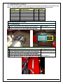
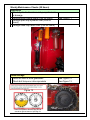
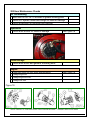
Daily Maintenance Checks
Air Conditioning
Check compressor belt tension and condition
Check condenser for blockage and damage
See Figure 1
Figure 2
Figure 1
Gearbox Cooler
AC
CONDENSER
Main Cooler
Hydraulics
Check hydraulic oil level
See Figure 3
Check hydraulic system for leaks and damage
Check main cooler for blockage and damage
Check gearbox cooler for blockage and damage See Figure 2
Figure 3
BH410-22-REV A
29
1/10/2007
Undercarriage
Clean chains and rollers of dirt and debris
Check chain tension
Check for loose or damaged pads
Check for leaks and loose bolts on drives
Figure 4
See Figure 4
See Figure 5
Figure 5
Place straight edge as shown on tracks.
2” sag should be at center point as
indicated By the circle
Bolt torque specs are located in the FTX440 parts manual
Lifting Gear
Grease lower pivot pins
Grease attaching pins
See Figure 6
Figure 6
BH410-22-REV A
30
1/10/2007
Engine
Check engine oil level
Check radiator coolant level
Check coolant system for leaks or damage
Check fan belt tension and condition
Check radiator and charge air cooler for
blockage and damage
Check dust collector for dust
Check fuel filter for water and dirt
Figure 7
Figure 8
Figure 9
Figure 10
BH410-22-REV A
31
See Figure 7
See Figure 8
See Figure 9
See Figure 2
See Figure 10
1/10/2007
Weekly Maintenance Checks (50 Hours)
Hydraulics
Check hydraulic drive lines and pumps for leaks
or damage
Change pump charge filters (First 50 hours)
Change open loop hydraulic filter (First 50
hours)
Change close loop return filter (First 50 hours)
See Figure 11
Figure 11
Undercarriage
Check oil level in drive gearboxes
Check bolt torque on drive sprockets
See Figure 12
See Figure 13
Figure 13
Figure 12
Place in fill position. Remove pug 1B. Oil
should be right at bottom of opening 1B.
BH410-22-REV A
32
1/10/2007
Lifting Gear
Grease top link cylinder pins
See Figure 14
Figure 14
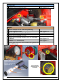
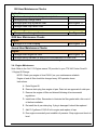
Engine
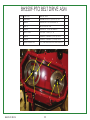
Check clamps on air filter and plumbing
Clean engine air filter
See Figure 15
Check pre-cleaner system for leaks
Check fluid coupling oil level
Check fluid coupling exhaust vent for blockage
or debris
See Figure 16
Grease PTO drive shafts
See Figure 17
Check bolt torque on drive shafts and gearboxes
(First 50 hours)
Figure 17
Figure 16
Figure 15
Remove wing nut,
disassemble and clean
the filter elements with
compressed air.
Grease fittings
On both ends of
PTO shaft.
51044-02
51044-01
BH410-22-REV A
33
1/10/2007
200 Hour Maintenance Checks
Air Conditioning
Start and run A/C for 10 minutes to grease running parts
Check A/C system hoses and fittings for leaks or damage
Check evaporator for blockage and damage
Hydraulics
Check drive motors for leaks or damage
See Figure 18
Figure 18
Undercarriage
Check drive motor and gearbox mounting bolts
Engine
Check bolt torque on drive shafts and gearboxes
See Figure 19
Change engine oil
Change engine oil filter
Change fuel filter
Figure 19
NOTE: REFER TO THE PARTS SECTION FOR DRIVE SHAFT TORQUE SPECIFICATIONS
BH410-22-REV A
34
1/10/2007
500 Hour Maintenance Checks
Hydraulics
Perform oil sample test, change as required
Change pump charge filters
Change open loop hydraulic filter
Change close loop return filter
See Figure 11
Undercarriage
Change oil on drive gearboxes
See Figure 16
2000 Hour Maintenance Checks
Engine
Change oil in fluid coupling
See Figure 17
Annual Hour Maintenance Checks
Engine
Change main engine air filter
See Figure 15
Change safety element at every third maintenance of main filter
Please refer to the BH350-PTO Manual for Bull Hog Maintenance information.
3.4 - Engine Maintenance
Note: Refer to the Cat C-13 Engine manual CD provided in your FTX-440 Carrier Care Kit.
1. Engine Oil Change
NOTE: Check your engine oil level DAILY per your maintenance schedule
Engine oil and oil filter should be changed every 200 operation hours.
Instructions:
A. Drain Engine Oil
B. Remove drain plug from engine oil pan. Drain into an approved oil catch pan.
C. Remove the engine oil filter and discard following all environmental
regulations.
D. Install new oil filter. Remember to lubricate the filter gasket with a thin coat of
oil before installation.
E. Re-install the oil pan drain plug. If plug is damaged it should be replaced.
F. Add 10.5 gallons of 15W-40 oil to engine and replace oil cap.
G. Run engine momentarily and establish oil pressure. Stop engine and check oil
level.
BH410-22-REV A
35
1/10/2007
2. Air Filter Change.
Remove wing nut,
disassemble and
change the filter
elements with correct
replacement filters.
Fecon Part No.
51044-02
Fecon Part No.
51044-01
BH410-22-REV A
36
1/10/2007
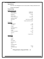
Air Conditioning System
Specifications:
The HVAC unit is designed for use in driver cabins of heavy construction and
commercial equipment.
Technical Data:
Heating and AC unit
Heat Capacity:
31600 btu/hr
Cooling Capacity
33070 btu/hr
Refrigerant:
R134A
Rated Voltage:
24V
Current Consumption:
11.2 A max
Operating Voltage:
24V
Airflow max:
430 ft³/h (free blowing)
Fan:
3-speed permanent magnet
Condenser
Heat Capacity:
-,- kW
No. of Fan:
1 x axial
Voltage:
24V
Operating Pressure
bar
Refrigerant:
R134A
Weight
lb
Current Consumption:
-,- A max
Airflow ca:
ft³/h
Fan:
Long life motor
Compressor
Model:
Drilling:
Stroke:
No. Cylinder:
Revolution max:
Output:
Rotating direction:
Refrigerant:
R134A
Operating Voltage:
24V
Oil:
Filling quantity for refrigerant R134A = - - oz
BH410-22-REV A
37
1/10/2007
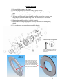
Servicing
Important:
The AC unit must be switched on shortly every 3 months in order to lubricate all running
parts and prevent sticking of compressor.
The AC unit must be serviced annually by a trained service representative. (Preferably
in the cooler months of the year)
Prior to, halfway through and at the end of the cooling season, the following service
steps must be carried out to ensure proper operation of your AC unit:
Belt Tension and Compressor seat check.
Checking refrigerant level and checking for humidity in the unit.
Cleaning the Condenser
The blades of the condenser must be cleaned carefully with high pressure.
They will be damaged otherwise and no air would pass through the
condenser.
The annual check in the service workshop should be carried out in the beginning
of the warmer months of the year and documented in your maintenance schedule.
Cab Maintenance
BH410-22-REV A
38
1/10/2007
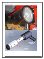
Cab sliding Instructions - To move the cab forward use the hand pump shown below.
This will allow access to the hydraulic pump. See Parts Section for part numbers and
locations.
Hand pump
Cab Movement Directional Valve
Note the location of the Directional valve for moving the cab. In the position shown in
the photo the hand pump will move the cab BACK into operating position. This is the
correct position for operating the FTX-440. To move the cab, turn the directional valve ¼
turn to the left. Use hand pump to move cab forward. Once maintenance is complete
turn directional valve ¼ turn to the right into position shown in photo and use hand
pump to move cab back.
BH410-22-REV A
39
1/10/2007
Part 4 - Troubleshooting
HVAC Troubleshooting
Malfunction
Unit does not cool down
Unit cools down only for a
short time.
Unit does not sufficiently cool
down
Cause
Electrical connections
interrupted
Air temp sensor defect
Thermostat defect*
Turn potentiometer defect**
Relay defect
Fuse defect
Compressor stops from
exceeding max operating
pressure*
Filter dryer blocked*
Too much refrigerant*
Compressor stops from
running below min operating
pressure*
Magnet coupling defect on
compressor.*
Belt broken
Icing of condenser*
Check electronic control
device
Not enough air passage
Not enough refrigerant in
Solution
Check connections of
magnetic coupling, switch,
relay, temp sensor and
control unit
replace
replace
replace
replace
replace
Clean condenser, check
function of condenser fan
Replace filter dryer
Suction excess refrigerant
Check impermeability, maybe
refill refrigerant
Replace spool
Replace belt
Adjust temperature of icing
protection on thermostat.
Clean blades of condenser
and vaporizer
Fill unit to recommended level
system
Expansion valve blocked*
Loud noise on the
compressor
Whistle noise on the belt
Clean expansion valve or
replace
Expansion valve iced from too Replace filter dryer.
much liquid in unit*
Identifiable by red humidity
tracer.
Filter dryer partly blocked
Replace filter dryer
from icing on the dryer*
Air in refrigeration cycle with
Evacuate unit and fill newly
exceeded pressure and blister
in inspection glass*
Leaking ball bearing in
Replace ball bearing
compressor*
Magnet coupling defect*
Replace magnet coupling
Not enough oil in compressor Add oil
Belts worn out
Replace belt
Belts too slack
Tighten belt
*= to be carried out by HVAC technician.** = if available.
BH410-22-REV A
40
1/10/2007
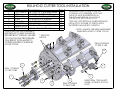
Clutch Troubleshooting
Symptom
Clutch slip
and/ or
Overheating.
Noise and / or
overheating
output bearing
carrier.
Step Cause
1
Driving Plates
Check plates for wear.
Check Driven machine.
Check engine RPM
2
Low oil Pressure
Check oil pressure feeding system
Check segments 104
Check for possible oil loss.
1
2
3
4
Oil Circuit
Bearing failure
Radial load too high
Slip Plates
5
Misalignment
6
Torsional Vibration
Tooth wear on driving ring and/or
clutch plates.
Check oil circulation and heat exchanger
Replace bearing.
Check transmission and alignment.
Check oil pressure.
See alignment section (Installation
paragraph 4)
Contact Transfluid
Dismantle and replace driving ring
and/or clutch plates.
1
O-ring worn or damaged.
Replace bad O-ring.
1
2
Residual pressure > 0 psi
Engine rpm not at minimum.
3
Presence of dirt between internal
and external teeth of plates.
Check disengaging pressure.
Check engine rpm at minimum.
Remove Dirt. Check the Housing all
holes must be closed and all window
openings must be sealed with gasket.
7
Oil leakage at
clutch side.
Not completely
disengaging.
(drag of load,
smoke from
clutch).
Remedy
Final Drive Troubleshooting
Symptom
Step Cause
Remedy
Overheating.
1
2
3
Low oil level
Hydraulic oil too warm
Brake not fully released
Check and refill oil
Check hydraulic circuit
Check brake release pressure
Insufficient
braking torque
1
2
3
Parking brake malfunction
Disc brakes worn
Damaged Parts
Replace disc brake pads
Check Brake components
Sprocket
Locked
1
2
Parking Brake Locked
Mechanical components damaged
Check the complete brake release
Replace damaged parts
Oil Leakage
from lifetime
seal
1
Lifetime seal damaged
Replace seal
Oil Leakage
from end cover
1
O-Ring Seal damaged
Replace seal
1
Plug seal damaged
Replace seal
1
Hydraulic circuit malfunction
Verify operation of Hydraulic circuit.
Oil Leakage
from cover
plugs.
Hydraulic
noise on slow
down
BH410-22-REV A
41
1/10/2007
Hydraulic
noise inside
gear motor
1
Internal damage
Check the gearbox
Drive Pumps Troubleshooting
Symptom
Neutral difficult
or impossible
to find
System
Operating Hot
Transmission
operated
properly in one
direction only.
System will not
operate in
either direction
Step Cause
1
Input to pump control module is
operating improperly
Check control input. Repair or replace as
necessary.
2
Check pump displacement control.
Control linkages may not be secure
or control orifices are blocked.
Adjust, repair or replace as necessary.
(See attached series 90 manual)
3
Repair or replace pump.
Consult Sauer-Sundstrand Authorized
Service Center.
1
Check oil level in Reservoir
2
Heat exchanger not working
properly.
3
Check for low charge pressure.
Measure charge pressure. Inspect and
adjust (or replace) charge relief valve, or
repair leaking charge pump.
4
Check vacuum at charge inlet for
restricted lines or dirty filter
Replace filter if needed. Ensure lines are
clear and of sufficient size.
5
Check system relief pressure
settings to ensure they are not too
low.
Verify settings of pressure limiters and
high pressure relief valves. Adjust or
replace multi function valves as
necessary.
6
Check motor for internal leakage
(that will produce low side system
pressure and overwork the
system).
Monitor motor case flow without loop
flushing the circuit. (See attached series
90 manual) If flow is excessive replace
motor.
7
Check for high system pressure
8
Replace transmission
Measure system pressure. If too high
reduce loads.
Replace pump and motor.
1
Input to pump control module is
operating improperly
Check control input. Repair or replace as
necessary.
2
Check pump displacement control.
Control linkages may not be secure
or control orifices are blocked.
Adjust, repair or replace as necessary.
(See attached series 90 manual)
3
Interchange system pressure
limiters, high pressure relief valves
and check system valves
Interchange multi function valves. If the
problem changes direction, repair or
replace the valve for the non-operational
side.
4
Check charge pressure. If it decays
in one direction the loop flushing
valve may be sticking in one
direction.
Measure charge pressure in forward and
in reverse. If the pressure decays in one
direction, inspect and repair the motor
loop.
Check oil level in Reservoir
Input to pump control module is
operating improperly
Fill reservoir to proper level
Check control input. Repair or replace as
necessary.
Check pump displacement control.
Control linkages may not be secure
or control orifices are blocked.
Adjust, repair or replace as necessary.
(See attached series 90 manual)
1
2
3
BH410-22-REV A
Remedy
Fill reservoir to proper level
Check air flow and input temperature for
heat exchanger. Clean, repair or replace
heat exchanger.
42
1/10/2007
4
Ensure that bypass valves are
closed. (Open bypass valve will
depressurize loop).
Close bypass valves. Replace multi
function valve if defective.
5
Check charge pressure with pump
in neutral. Low charge pressure will
not re-charge system loop.
If pressure is low, go to next step. (see
section 4.2 for table of correct pressure
readings)
Check charge pressure with pump
in stroke.
Low pressure in stroke indicates a motor
charge relief valve or system pressure
relief valve may be improperly set. If
pressure is low, adjust or replace motor
charge relief valve. If pressure ok go to
step 9.
6
12
Inspect pump charge relief valve
for leaks or improper setting
Check charge pump inlet filter for
clogging.
Check charge pump for sufficient
charge flow.
Check system pressure
Check for defective system multifunction valves.
Replace transmission
1
Low system pressure at motor
If pressure at motor is low, increase
setting of pressure limiter.
2
Variable motor stuck in minimum
displacement
Check control supply pressure or repair
displacement control. Check motor
control orifices.
3
Check for internal leakage
4
Replace transmission
1
Check oil level in Reservoir
2
Check for low charge pressure.
3
Check pump output flow to ensure
swash plate is not out of position.
4
Check variable motor displacement
control to ensure swash plate is not
out of position.
Repair or replace control.
1
Check oil level in Reservoir
Fill reservoir to proper level
2
Air in system (Can lead to
cavitation).
Look for foam in reservoir. Look for leaks
on inlet side of system loop. Afterwards
let reservoir settle until bubbles are
gone. Run system at low speed to move
system fluid to reservoir. Repeat.
3
Check pump inlet for high vacuum
4
Shaft coupling may be loose.
5
Shafts not aligned properly
7
8
9
10
11
Low Motor
Output Torque
Improper
motor output
speed
Excessive
Noise and / Or
Vibration
BH410-22-REV A
Adjust or replace charge relief valve as
necessary.
Replace filter if necessary.
Repair or replace the charge pump.
If low system pressure go to next step.
Repair or replace bad valves
Replace pump and motor.
Check o-rings, gaskets and fittings for
leaks. Repair or replace as needed.
Replace pump and motor.
43
Fill reservoir to proper level
Measure charge pressure. Inspect and
adjust charge system as needed.
Measure pump flow by teeing into
outflow hose. Check for proper pump
speed and ensure that pump is in full
stroke.
Replace inlet filter as needed. Check for
proper suction line size.
Replace loose shaft couplings in charge
pump or replace pump or motor.
Align shafts.
1/10/2007
1
2
System
response is
sluggish
BH410-22-REV A
3
4
5
Check oil level in Reservoir
Check settings on multi-function
valves.
Check pump inlet vacuum
Check prime mover speed
Check charge and control
pressures
6
Check system internal leakage
7
Replace transmission
44
Fill reservoir to proper level
Adjust and / or replace multi function
valves.
If inlet vacuum high, replace inlet filter.
Adjust engine speed
Correct as needed
Check o-rings, gaskets and fittings for
leaks. Repair or replace as needed.
Replace pump and motor.
1/10/2007
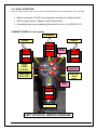
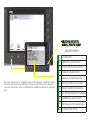
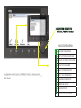
IQAN OPERATING INSTRUCTIONS
FOR THE
FECON FTX440 CARRIER
A= ENGINE DISPLAY
B= TRACK DISPLAY
C= PTO DISPLAY
D= TEMPERATURE DISPLAY
= MENU
= SELECTOR: ROTATE TO
SCROLL, PUSH TO SELECT
= BACK
F1= HOME
F4 = DIAGNOSTICS
F5 = INFORMATION
Startup Screen appears when the machine key is turned on. Follow the provided
navigation and become familiar with each screens functions. The F1 button will
return you to this screen from all areas other than the menu. When you are in the
menu area, use the back button to return.
B= TRACK DISPLAY
C= PTO DISPLAY
D= TEMPERATURE DISPLAY
= MENU
= BACK
F1= HOME
F5 = INFORMATION
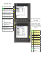
Push button A at the startup screen to open the Engine screen. All engine activity
is monitored here.
A= ENGINE DISPLAY
C= PTO DISPLAY
D= TEMPERATURE DISPLAY
= MENU
= BACK
F1= HOME
F5 = INFORMATION
Push button B at the startup screen to open the Track screen. All Track activity is
monitored here.
A= ENGINE DISPLAY
B= TRACK DISPLAY
D= TEMPERATURE DISPLAY
= MENU
= BACK
F1= HOME
F5 = INFORMATION
Push button C at the startup screen to open the PTO screen. All PTO Drive activity
is monitored here.
A= ENGINE DISPLAY
B= TRACK DISPLAY
C= PTO DISPLAY
= MENU
= BACK
F1= HOME
F5 = INFORMATION
3XVKEXWWRQ'DWWKHVWDUWXSVFUHHQWRRSHQWKH7HPSHUDWXUHVFUH
Temperature are monitored here.
TO DIAGNOSTIC SCREEN
= MENU
= BACK
F1= HOME
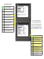
Push F5 button at the startup screen to see hours logged, serial number and other
RQIRUPDWLRQDERXWWKH)7;
A = MAINTENANCE
B = SHUT DOWN TEST
C = FLUID COUPLER PROTECTION
RED=OFF GREEN = ON
= MENU
= BACK (to last page)
F1= HOME
Push F4 button at the startup screen (or the “C” button from the information
screen)to access the Diagnostic screen. The various lights indicate operating
conditions in various systems.
Green light = good / on
Red light = warning / off
Black = Inactive
Yellow = Alarm
The maintenance screen can be accessed from here. You can perform an
engine shut down test as well as switch on the fluid coupler protection.
RECORD ENGINE OIL CHANGE
RECORD HYD OIL CHANGE
= MENU
= BACK (to last page)
F1= HOME
F5 = INFORMATION
The service screen can be used to record and track scheduled maintenance on
WKH)7;7KHRSWLRQVDUHSDVVZRUGSURWHFWHG
= SELECTOR: ROTATE TO
SCROLL, PUSH TO SELECT
ADJUST MENU
The adjust screen has a “scrollable” menu to access many machine functions.
These are adjust items that will effect machine performance if not adjusted
correctly. These items are to be adjusted by qualified technicians or engineers
only.
MACHINE SPECS
CURRENT OUT ADJUST GROUP
VOLTAGE INPUTS ADJUST GROUP
ENGINE OIL SERVICE GROUP
HYDRAULIC OIL SERVICE GROUP
STRAIGHT TRACKING LOW RANGE
STRAIGHT TRACKING HIGH RANGE
TEMP/PRESSURE SENSOR PARAMETERS
REVERSIBLE FAN ADJUST GROUP
ADDITIONAL FACTORY ADJUSTMENT
CONTROLS FILTER GROUP
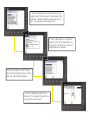
1. The Technician will choose the item from the
Adjust menu that may need to be adjusted. This
example “Straight Tracking, Low Range is chosen.” A password screen will appear.
2. Use the dial selector to enter the
password. Once the password is en
tered by the Technician, a menu of
adjustable items appears.
3. In this example the Tech chooses
the “+Left Low Range Creep” param
eter. The adjust dial will appear.
4. The Tech will make adjustments
based on th troubleshooting that has
brought him to this screen.
= SELECTOR: ROTATE TO
SCROLL, PUSH TO SELECT
MEASURE MENU
The measure screen has a “scrollable” menu to observe many
machine processes. These items can be useful in troubleshooting
minor issues.
ENGINE PARAMETERS
LEFT JOYSTICK FUNCTIONS
RIGHT JOYSTICK FUNCTIONS
TRACK PARAMETERS
FAN CONTROL GROUP
PTO / CLUTCH GROUP
TEMPERATURE GROUP
PRESSURE GROUP
DIAGNOSTICS
MODULE DIAGNOSTICS
MEASURE MENU
ENGINE PARAMETERS
THE FIRST EIGHT (SHADED) MENU ITEMS
ARE SHOWN ON INITIAL OPENING OF
THE ENGINE PARAMETERS SCREEN. BY
USING THE DIAL SELECTOR ALL OF THE
ITEMS LISTED BELOW CAN BE ACCESSED.
ENGINE PARAMETERS
LEFT JOYSTICK FUNCTIONS
RIGHT JOYSTICK FUNCTIONS
TRACK PARAMETERS
FAN CONTROL GROUP
PTO / CLUTCH GROUP
TEMPERATURE GROUP
PRESSURE GROUP
DIAGNOSTICS
MODULE DIAGNOSTICS
AMBER WARNING LAMP
ENGINE SPEED
ACTIVE DIAG TROB CODES, PRE
ACTUAL ENGINE % TORQUE
PROTECT LAMP PRE
ENGINE OIL PRESSURE
OCCURENCE COUNT PRE
ENGINE CHARGE VOLTAGE
FMI PRE
ENGINE COOLANT TEMP
63102676,*1,),&$17%,
FUEL GUAGE
6316(&21'%<7(35(
LOW FUEL LEVEL SWITCH
631/($676,*1,),&$17%
ACTIVE DIAG TROB CODES
RED STOP LAMP PRE
PROTECT LAMP
AMBER WARNING LAMP PRE
OCCURENCE COUNT
ENGINE TURBO CHARGE BOOST PRESSURE
FMI
ENGINE TOTAL FUEL USED
63102676,*1,),&$17%,76
ENGINE FUEL DELIVERY PRESSURE
6316(&21'%<7(
ENGINE COOLANT LEVEL
631/($676,*1,),&$17%,76
ENGINE FUEL RATE
RED STOP LAMP
ENGINE FUEL TEMPERATURE
ENGINE INTAKE 1 MANIFOLD TEMPERATURE
ENGINE CHECK
MEASURE MENU
ENGINE PARAMETERS
LEFT JOYSTICK FUNCTIONS
RIGHT JOYSTICK FUNCTIONS
TRACK PARAMETERS
FAN CONTROL GROUP
PTO / CLUTCH GROUP
TEMPERATURE GROUP
PRESSURE GROUP
DIAGNOSTICS
MODULE DIAGNOSTICS
LEFT AND RIGHT JOYSTICK
FUNCTIONS
THE FIRST EIGHT (SHADED) MENU ITEMS
ARE SHOWN ON INITIAL OPENING
OF THE RIGHT JOYSTICK FUNCTIONS
SCREEN. BY USING THE DIAL SELECTOR
ALL OF THE ITEMS LISTED BELOW CAN BE
ACCESSED.
RAISE / LOWER
RAISE / LOWER COUT
RAISE / LOWER FILTER
TILT UP / DOWN
TILT UP / DOWN COUT
TILT UP / DOWN FILTER
PUSH BAR RAISE
PUSH BAR RAISE DOUT
PUSH BAR LOWER
PUSH BAR LOWER DOUT
HORN
HORN DOUT
MEASURE MENU
ENGINE PARAMETERS
LEFT JOYSTICK FUNCTIONS
RIGHT JOYSTICK FUNCTIONS
TRACK PARAMETERS
FAN CONTROL GROUP
PTO / CLUTCH GROUP
TEMPERATURE GROUP
PRESSURE GROUP
DIAGNOSTICS
TRACK PARAMETERS &
FAN CONTROL GROUP
THE FIRST EIGHT (SHADED) MENU ITEMS
ARE SHOWN ON INITIAL OPENING OF
THE FAN CONTROL GROUP SCREEN. BY
USING THE DIAL SELECTOR ALL OF THE
ITEMS LISTED BELOW CAN BE ACCESSED.
MODULE DIAGNOSTICS
COOLING FAN MAN REVERSE
FAN CONTROL SMC
COOLING LOGIC DMAC
HYD COOLER FAN CONTROL
COUT
ENG COOLING FAN REVERSE
DOUT
FAN REVERSE SPEED
FAN FORWARD TIME SET
FAN FORWARD TIMER
FAN REVERSE TIME SET
FAN REVERSE TIMER
MEASURE MENU
ENGINE PARAMETERS
PTO / CLUTCH GROUP
LEFT JOYSTICK FUNCTIONS
RIGHT JOYSTICK FUNCTIONS
TRACK PARAMETERS
FAN CONTROL GROUP
PTO / CLUTCH GROUP
TEMPERATURE GROUP
PRESSURE GROUP
DIAGNOSTICS
MODULE DIAGNOSTICS
THE FIRST EIGHT (SHADED) MENU ITEMS
ARE SHOWN ON INITIAL OPENING OF
THE PTO / CLUTCH GROUP SCREEN. BY
USING THE DIAL SELECTOR ALL OF THE
ITEMS LISTED BELOW CAN BE ACCESSED.
CLUTCH ON/OFF
CLUTCH ON/OFF DOUT
PTO ENGAGE TIMER
HIGH RPM BLOCK
FLUID COUPLING SPEED PICKUP
FLUID COUPLING SPEED (RPM)
FLUID COUPLING SLIP
GEAR BOX TEMPERATURE
GEAR BOX SHUT DOWN
7(03(5$785('(*
GEAR BOX RESET TEMPERATURE
'(*)
HIGH GEAR BOX SHUT DOWN
MEASURE MENU
ENGINE PARAMETERS
LEFT JOYSTICK FUNCTIONS
RIGHT JOYSTICK FUNCTIONS
TRACK PARAMETERS
FAN CONTROL GROUP
DIAGNOSTICS
PTO / CLUTCH GROUP
THE FIRST EIGHT (SHADED) MENU ITEMS
ARE SHOWN ON INITIAL OPENING OF
THE DIAGNOSTICS GROUP SCREEN. BY
USING THE DIAL SELECTOR ALL OF THE
ITEMS LISTED BELOW CAN BE ACCESSED.
TEMPERATURE GROUP
PRESSURE GROUP
DIAGNOSTICS
MODULE DIAGNOSTICS
SEAT SWITCH
CLOSED LOOP RETURN FILTER
OPEN LOOP RETURN FILTER
AIR FILTER ALARM
LEFT CHARGE FILTER BYPASS
RIGHT CHARGE FILTER BYPASS
LOW HYD OIL LEVEL SWITCH
LOW FUEL LEVEL SWITCH
ENGINE SHUT DOWN TEST
SWITCH
ENGINE SHUT DOWN
OPEN LOOP TEMP MESSAGE
CASE TEMP MESSAGE
GEAR BOX TEMP MESSAGE
ENGINE COOLANT TEMP
ENGINE CHECK
MEASURE MENU
MODULE DIAGNOSTICS
ENGINE PARAMETERS
LEFT JOYSTICK FUNCTIONS
THE FIRST EIGHT (SHADED) MENU ITEMS
ARE SHOWN ON INITIAL OPENING OF
THE MODULE DIAGNOSTICS GROUP
SCREEN. BY USING THE DIAL SELECTOR
ALL OF THE ITEMS LISTED BELOW CAN BE
ACCESSED.
RIGHT JOYSTICK FUNCTIONS
TRACK PARAMETERS
FAN CONTROL GROUP
PTO / CLUTCH GROUP
TEMPERATURE GROUP
PRESSURE GROUP
DIAGNOSTICS
MODULE DIAGNOSTICS
7(03(5$785(>'(*&@
TEMPERATURE [DEG C], MDL
6833/<92/7$*(>9@;
SUPPLY VOLTAGE [V], MDL
5()92/7$*(>9@;$
REFERENCE VOLTAGE [V], MDL
02'8/(67$786;$$
UTILIZATION [%]
TEMPERATURE [DEG C] XT2
GSM SIGNAL QUALITY [%]
SUPPLY VOLTAGE [V] XT2
SYSTEM STATUS
REF VOLTAGE [V] XT2
INTERNAL SD CARD STATUS
MODULE STATUS XT2
EXTERNAL SD CARD STATUS
MALFUNCTION ECM
MACHINE ID
AMBER WARNIG ECM
7(03(5$785(>'(*&@;$$
MODULE STATUS ECM
6833/<92/7$*(>9@;$$
PROTECT ECM
MODULE STATUS, MDL
5()92/7$*(>9@;$$
02'8/(67$786;$$
7(03(5$785(>'(*&@;$$
Rev D 1-3-07
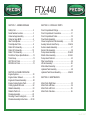
FTX-440
CONTENTS
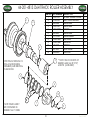
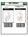
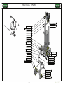
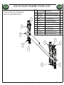
SECTION 1 - UNDERCARRIAGE
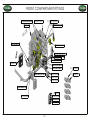
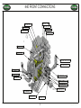
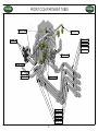
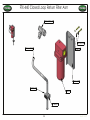
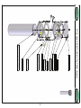
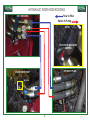
SECTION 3 - HYDRAULIC PARTS Safety First.............................................. 2 Front Compartment Fittings.................................. 30
Serial Number Location........................... 3
Front Compartment Connections ......................... 31
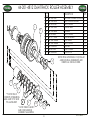
Undercarriage Assembly .........................5
Front Compartment
Tubes ................................... 32
Undercar riage BOM ...............................6
Flow Divider Assembly...........................................33
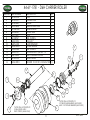
Idler Track Adjuster...................................7
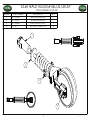
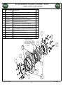
Closed Loop Return Filter Assembly .................... 34
Track Adjuster Parts................................ 8
Auxilary Valve & Hand Pump ....................... 35 & 36
Roller 4812 Assembly...............................9
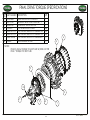
Suction Header Assembly .....................................37
Roller 4813 Assembly.............................10
Return Filter Assembly ......................................... 38
Roller 1781 Assembly ............................11
Pump Hoses Assembly................................. 39 & 40
Final Drive Torque Specifications ...........12
Shuttle Valve Assembly ............................... 41 & 42
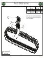
Track Group ............................................13
Pump Hose Parts List .......................................... 43
600 700 mm Track ..................................14
Filter Hose Routing .............................................. 44
800 900 mm Track ..................................15
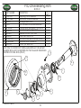
Lift Arm Assembly ................................................ 45
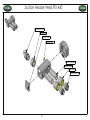
Motor Mount Assembly ........................................ 47
Hydraulic Tank Assembly ..................................... 48
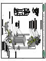
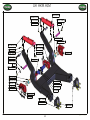
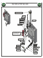
SECTION 2- ENGINE DRIVELINE
Hydraulic Tank Mount Assembly .................. 49 & 50
Engine Systems......................................18
SECTION 4 - MAINTENANCE
Engine Intake / Exhaust .........................19
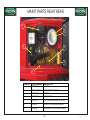
Engine Air Cleaner Assembly .................20 Maint. Parts Right Rear......................................... 53
Engine Cooling System Parts ................ 21
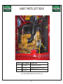
Maint. Parts Left Rear........................................... 54
Cooling System Parts List ..................... 22
Maint. Parts Left Front.......................................... 55
Radiator Assembly ................................ 23
Maint. Parts Cab Area.......................................... 56 Radiator Parts List ................................ 24
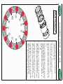
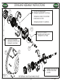
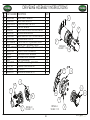
Driveline Assembly ............................... 25
Mounting Power Locking Hub .............. 26
Driveline Assembly Instructions.........27-28
Rev D 1-3-07
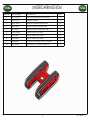
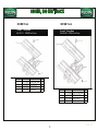
SAFETY FIRST
> With any piece of equipment, new or used, the most important part of its operation is safety! > It is important that the safety video is viewed before operating this equipment.
> Fecon Inc. encourages you and your employees to familiarize yourselves with your new equipment and to stress safe operation.
>This symbol is used to call attention to safety procedures.
Read all the instructions in this manual
before operating the equipment.
2
Rev D 1-3-07
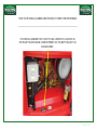
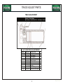
FIND YOUR SERIAL NUMBER AND RECORD IT HERE FOR REFERENCE
______________________________________________________________
______________________________________________________________
THE SERIAL NUMBER FOR YOUR FTX440 CARRIER IS LOCATED IN
THE RIGHT REAR ENGINE COMPARTMENT ON THE BOTTOM LEFT AS
SHOWN HERE.
Rev D 1-3-07
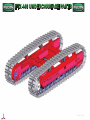
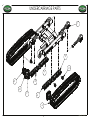
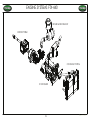
FTX-440 UNDERCARRIAGE PARTS
Rev D 1-3-07
5
Rev D 1-3-07
6
Rev D 1-3-07
7
Rev D 1-3-07
GROUP NUMBER / PART BREAKDOWNS
TRACK ADJUST PARTS
FTX440 UNDERCARRIAGE
TRACK ADJUSTMENT
Group # Group Name
44-179-2998 ADJUSTMENT GP - HYDRAULIC TRACK
Ref #
1
2
3
4
5
6
7
8
9
10
Part#
QTY
Part Name
2S-5926
1
Fitting - Grease
7Y-1257
2
Ring
- Backup
093-1514
2
Ring - Backup
095-2927
1
Valve
- Fill
099-0121
1
Seal
- Lip Type
113-2824
1
Plate
As
179-3007
1
Piston
179-3008
1
Cylinder
095-1622
2
Seal - O - Ring
8T-4191
2
Bolt (M10X1.5X16-MM)
8
Rev D 1-3-07
9
Rev D 1-3-07
10
Rev D 1-3-07
11
Rev D 1-3-07
12
Rev D 1-3-07
NOTE: ITEMS 1 AND 2 PART NUMBER DEPENDS
ON TRACK WIDTH. FOLLOWING PAGES HAVE
TRACK WIDTH DETAILS.
13
Rev D 1-3-07
GROUP NUMBER / PART BREAKDOWNS
ROUP NUMBER / PART BREAKDOWNS
600MM , 700MM TRACK
FTX440 UNDERCARRIAGE
FTX440 UNDERCARRIAGE
Ref #
1
2
3
4
600 MM Track
700 MM Track
Group # Group Name
44-22-1253 600MM Track Group
Group # Group Name
44-224-1252 700MM Track Group
Part #
QTY
213-1932
1
6Y-0846
192
9W-3361
192
152-8628
48
Ref #
1
2
3
4
Part Name
Link As - Track
Bolt - Track(M20X1.75X63-MM)
Nut - Track (M20X1.5-THD)
Shoe-Track
14
Part #
QTY
213-1932
1
8E-8814
48
6Y-0846
192
9W-3361
192
Part Name
Link As - Track
Shoe-Track
Bolt-Track
Nut - Track
Rev D 1-3-07
ROUP NUMBER / PART BREAKDOWNS
GROUP NUMBER / PART BREAKDOWNS
800MM, 900 MM TRACK
FTX440 UNDERCARRIAGE
Ref#
1
2
3
4
FTX440 UNDERCARRIAGE
800 MM Track
900 MM Track
Group # Group Name
44-124-153 800MM Track Group
Group # Group Name
44-168-6984 900MM Track Group
Part #
Qty
213-1932
1
6Y-2126
48
6Y0846
192
9W-3361
192
Part Name
Link
AsTrack
Shoe-Track
Bolt-Track
Nut-Track
Ref #
1
2
3
4
15
Part #
QTY
179-0696
1
168-6983
45
6Y-0846
180
9W-3361
180
Part Name
Link
As
Shoe- Track
Bolt - Track
Nut-Track
Rev D 1-3-07
FTX-440 Engine / Driveline
16
Rev D 1-3-07
THIS PAGE LEFT BLANK FOR LAYOUT PURPOSES
17
Rev D 1-3-07
18
Rev D 1-3-07
19
Rev D 1-3-07
20
Rev D 1-3-07
21
Rev D 1-3-07
22
Rev D 1-3-07
23
Rev D 1-3-07
24
Rev D 1-3-07
25
Rev D 1-3-07
Rev D 1-3-07
26
26
27
Rev D 1-3-07
28
Rev D 1-3-07
FTX-440 HYDRAULIC PARTS
29
Rev D 1-3-07
30
Rev D 1-3-07
31
Rev D 1-3-07
32
Rev D 1-3-07
33
Rev D 1-3-07
34
Rev D 1-3-07
35
Rev D 1-3-07
Rev D 1-3-07
36
37
Rev D 1-3-07
Rev D 1-3-07
38
39
Rev D 1-3-07
40
Rev D 1-3-07
41
Rev D 1-3-07
42
Rev D 1-3-07
43
Rev D 1-3-07
44
Rev D 1-3-07
45
Rev D 1-3-07
THIS PAGE LEFT BLANK FOR LAYOUT PURPOSES
46
Rev D 1-3-07
47
Rev D 1-3-07
48
Rev D 1-3-07
49
Rev D 1-3-07
50
Rev D 1-3-07
THIS PAGE LEFT BLANK FOR LAYOUT PURPOSES
51
Rev D 1-3-07
)7;0$,17(1$1&(
52
5HY'
MAINT. PARTS RIGHT REAR
53
Rev D 1-3-07
MAINT. PARTS LEFT REAR
54
Rev D 1-3-07
MAINT. PARTS LEFT FRONT
55
Rev D 1-3-07
MAINT. PARTS CAB AREA
56
Rev D 1-3-07
1-800-528-3113
www.fecon.com • 3460 Grant Drive •
Lebanon, Ohio, 45036
BULL HOG
ROTOR INSTALLATION
PROCEDURE
BHBH-BRGINSTBRGINST-65
BHBH-BRGINSTBRGINST-90
0
Bearing Installation Tool Kits:
65MM (2-1/2") Bearing Installation Tool Kit
P/N: BH-BRGINST-65
P/N
Description
Quantity
BH-BRGINST-001-01
BH-BRGINST-002-01
190046
B10-1120S-5
N10-11H-5
Bearing Installation Tool Retainer Cap
65MM Bearing Installation Tube
5/8-11 All Thread x 13" Long
5/8-11 NC Square Head Set Screw x 5" Long
5/8-11 NC Hex Nut
1
1
1
4
3
W10F
5/8 Flat Washer
5
90MM (3-1/2") Bearing Installation Tool Kit
P/N: BH-BRGINST-90
P/N
Description
Quantity
BH-BRGINST-001-01
BH-BRGINST-002-02
190046
B10-1120S-5
N10-11H-5
Bearing Installation Tool Retainer Cap
90MM Bearing Installation Tube
5/8-11 All Thread x 13" Long
5/8-11 NC Square Head Set Screw x 5" Long
5/8-11 NC Hex Nut
1
1
1
4
3
W10F
5/8 Flat Washer
5
Getting Started:
There are two methods to install the Bull Hog rotor.
• Method one, secure the Bull Hog rotor on a level, stable fixture i.e. steel
constructed horses or equivalent and lower the body into position.
• Method two, secure the Bull Hog body on a level, stable fixture i.e. steel
constructed horses, or carrier and lift the rotor into position. If carrier is used,
safety provisions must be made to ensure the body is stable and to protect
from cylinder bleed off.
This documentation will describe the first procedure in detail. If the second method
is to be used, a fork lift or two (2) ton hydraulic floor jacks can be used to lift and
lower the rotor in lieu of the Bull Hog body.
Bull Hog Orientation
Illustration 1
1
Preparation:
• Secure the Bull Hog rotor on level, stable fixture. The fixture used will need to be
sufficient to hold the entire weight of the assembled Bull Hog. Refer to Table 1.
• With a black permanent marker, mark each stub shaft to identify the side and
index of their current location. The stub shafts will be replaced on the same side
and index to preserve balancing.
Rotor Shaft Identification
Illustration 2
•
Remove both stub shafts using a 1/2" allen wrench. (5/8-11 Socket Head Cap
Screws x 2” long)
Rotor & Body Measurements
Illustration 3
•
•
•
Measure the Bull Hog body from the outside of the left bearing pilot to outside
the right bearing pilot.
o Record Body Measurement
Measure the Bull Hog rotor through the rotor’s center from outside of the left stub
shaft bolt face to outside of the right stub shaft bolt face.
o Record Rotor Measurement
Subtract the Rotor Measurement from Body measurement __________________
o Record Actual Difference Measurement _____________
2
TABLE 1
Excavator Units
Body
Dimension
Rotor
Dimension
Difference
Dimension
38-1/8"
50-5/8"
61-3/4"
38-1/4"
57-3/4"
60-5/8"
31-13/16"
44-1/4
55-5/16"
31-1/2"
51"
53-7/8"
6-5/16”
6-3/8”
6-7/16”
6-3/4”
6-3/4”
6-3/4”
Body
Dimension
Rotor
Dimension
Difference
Dimension
61-3/4"
72-7/8"
87"
87"
91"
91"
55-5/16"
66-7/16"
80-9/16"
80-1/4"
84-1/4"
82-5/8"
6-7/16”
6-7/16”
6-7/16”
6-3/4”
6-3/4”
8-3/8”
Body
Dimension
Rotor
Dimension
Difference
Dimension
50-5/8"
61-3/4"
72-7/8"
50-5/8"
61-3/4"
72-7/8"
44-1/4"
55-5/16"
66-7/16"
44-1/4"
55-5/16"
66-7/16"
6-3/8”
6-7/16”
6-7/16”
6-3/8”
6-7/16”
6-7/16”
Model
Body
Dimension
Rotor
Dimension
Difference
Dimension
BH80
BH85
BH99
BH120
BH250
BH350
57-3/4"
72-7/8"
87"
87"
91"
91"
51-5/16"
66-7/16"
80-9/16"
80-1/4"
84-1/4"
82-5/8"
6-3/4”
6-7/16”
6-7/16”
6-3/4”
6-3/4”
8-3/8”
Model
BH47EXC
BH62EXC
BH74EXC
BH40EXC-SD
BH80EXC
BH250EXC
Bearing Tool Kit
BH-BRGINST-65
BH-BRGINST-65
BH-BRGINST-65
BH-BRGINST-65
BH-BRGINST-65
BH-BRGINST-65
Bearing
Type
Stub Shaft
Clearance
Approx.
Weight
STD
STD
STD
HD
HD
HD
2"
2"
2"
2-1/8"
2-1/8"
2-1/8"
1936 lbs
2559 lbs
2950 lbs
3000 lbs
4400 lbs
6500 lbs
Bearing
Type
Stub Shaft
Clearance
Approx.
Weight
STD
STD
STD
HD
HD
HD
2"
2"
2"
2-1/8"
4"
4-1/2'
2400 lbs
2700 lbs
4400 lbs
4900 lbs
7200 lbs
8700 lbs
Bearing
Type
Stub Shaft
Clearance
Approx.
Weight
STD
STD
STD
STD
STD
STD
2"
2"
2"
2"
2"
2"
2000 lbs
2250 lbs
2580 lbs
2000 lbs
2250 lbs
2580 lbs
Bearing
Type
Stub Shaft
Clearance
Approx.
Weight
STD
STD
STD
STD
HD
HD
2"
2"
2"
2-1/2"
4"
4-1/2"
2700 lbs
3800 lbs
4500 lbs
5000 lbs
7100 lbs
8140 lbs
Hydraulic Units
Model
BH74H
BH85H
BH99H
BH120H-SD
BH250H
BH350H
Bearing Tool Kit
BH-BRGINST-65
BH-BRGINST-65
BH-BRGINST-65
BH-BRGINST-65
BH-BRGINST-65
BH-BRGINST-90
SkidSkid-Steer Units
Model
BH62SS
BH74SS
BH85SS
BH62FM
BH74FM
BH85FM
Bearing Tool Kit
BH-BRGINST-65
BH-BRGINST-65
BH-BRGINST-65
BH-BRGINST-65
BH-BRGINST-65
BH-BRGINST-65
PTO Units
•
Bearing Tool Kit
BH-BRGINST-65
BH-BRGINST-65
BH-BRGINST-65
BH-BRGINST-65
BH-BRGINST-65
BH-BRGINST-90
To determine amount of shimming required:
“Chart Difference Dimension” ___________
Minus
“Actual Difference Dimension” ___________
= Total Shim Thickness Required = ___________
NOTE: The total shim thickness should be distributed evenly between the floating and fixed sides
3
•
To determine if either the bearings flange or the rotor needs to be shimmed:
o If the actual difference recorded is less than Chart Difference Dimension,
put compensating half moon shims between the bearing flange and box
sidewall. Shim thickness = approximately ½ Total shim thickness
recorded above"
o If the actual difference recorded is more than Chart Difference Dimension,
put compensating ring shims between the Stub shaft flange and labyrinth
seal spacer. Shim thickness = approximately ½ Total shim thickness
recorded above"
Rotor & Housing Shims
Illustration 4
Example for BH250 PTO:
Chart difference dimension = 6-3/4”
Actual difference dimension = 6-3/8
Total shim thickness required is 1/8”
Actual difference is LESS than chart difference so bearing to be shimmed 1/16”
on each side.
NOTE: Shims are available in 1/16” increments, if the spacing requires an uneven
amount; the larger amount should be installed on the floating/right hand side. Refer to
illustration 1. Example: If 3/16” shim is required use a 1/16” shim on the
floating/right hand side and a 1/8” shim on the fixed/left side.
4
Installing Rotor and Stub Shafts:
• Temporarily install both bolting flanges by loosely securing the rings with (2)
bearing bolts as shown in Illustration 5. For BH74H, BH85H, BH99H,
BH47EXC, BH62EXC, BH74EXC, and all Skid-Steer models use 5/8-11 Grade 8
Hex Head Cap Screws 2” long. For all larger models and Severe Duty models use
5/8-11 Grade 8 Hex Head Cap Screws 2-1/4” long.
Bearing Retainer
Illustration 5
•
With an overhead crane or equivalent lift the Bull Hog body and lower directly
over rotor so that both stub shafts can be reinstalled through the bearing pilot
holes. Refer to illustrations 5 and 6.
Lifting Lug Locations
Illustration 6
•
•
•
•
Using a clean, dry cloth wipe both mating surfaces of the stub shaft and the rotor
pilot to clean the surface of any debris or dirt, apply a thin coat of anti-seize to
both mating surfaces.
Carefully install the stub shaft into rotor pilot, paying close attention to the
markings to insure proper placement and rotation. It may be necessary to sand
mating surfaces with an emery cloth to obtain proper fit.
Reinstall stub shaft bolts with Nordlock lock washers and lock tight to secure the
stub shaft. Use a cross bolt pattern to evenly draw the stub shaft snug against the
rotor end cap, into the pilot.
Make sure the stub shaft is properly aligned and it is not bound up. Once visual
alignment is checked, using the same cross bolt pattern technique, torque the bolts
to 180 ft/lbs.
5
•
Repeat for right side.
Installing Rotor Bearings:
• First install the left hand bearing, which is the fixed bearing and painted red.
• If shims are to be added to the rotor stub shaft, install them now by placing them
over the stub shaft and sliding them firmly against the shoulder. If uneven spacing
is required the smaller spacing should be installed now on the left side.
Installation of Rotor Stub Shaft Shims
Illustration 7
•
•
•
•
•
•
•
Coat both the rotor stub shaft and the inside of the Red, fixed bearing with antiseize and slide the bearing onto the stub shaft.
Index the bearing so the grease line hole is directed towards the grease line
bulkhead, ref to illustration 8 and 9. Install the (4) bearing alignment bolts
through four equally spaced holes of bearing flange into bearing bolting flange.
Remove the two temporary bolts holding bearing bolting flange in place. If shims
are to be added to the bearing, install them now retaining them with the (4)
bearing alignment bolts. See Illustration 8.
Mount the bearing installation tool by sliding it over the rotor stub shaft and
threading the puller bolt into the end of the rotor stub shaft.
Tighten the puller bolt nut until the bearing is firmly seated against the Bull Hog
stub shaft shoulder.
First install and snug (4) bearing bolts with Nordlock lock washers and lock tight.
Then, remove the (4) bearing alignment bolts and replace with the remaining (4)
bearing bolts with Nordlock lock washers and lock tight.
Remove the bearing installation tool.
Torque the (8) bearing bolts using a cross bolt pattern to 180 ft/lbs.
6
Bearing Installation
Illustration 8
•
•
Check stub shaft clearance as shown in illustration 9. Ref to Table 1 on page 3 for
the recommended stub shaft clearance for your Bull Hog model. The clearance
tolerance is ±1/16”.
Assemble the grease line to the bearing housing and the grease line elbow.
Grease Line & Stub Shaft Clearance
Illustration 9
Repeat the “Installing Rotor Bearings” steps to install the right side bearing. The right
side bearing is a floating type bearing and is painted black. Ensure the bearing shaft
spacers are seated properly before installation.
•
•
Once both bearings have been installed and torqued, lift the Bull Hog body to free
the rotor. Spin the rotor by hand to ensure proper alignment and make sure the
rotor is not bound up. If the rotor does not spin by hand check the bearings to
ensure proper alignment and the rotor stub shafts to ensure they are properly
seated and aligned.
NOTE: The center of gravity has changed dramatically; reposition the
lifting chains to the lifting lugs located over rotor to accommodate
this shift.
Reinstall drive sheaves and drive belts. Replace belt housing covers. Lube grease
lines.
7
Bearing Rebuild
1. Disassemble the bearing to be rebuilt
2. Clean all components with solvent to remove grease and dirt.
3. Inspect all surfaces for damage and wear. Replace damaged and excessively worn
parts.
4. The laminar rings (Item 10) should always be replaced.
5. The Inner and Outer seals, (items 8 and 9) should be checked for excessive wear
along the path where the laminar rings rotate. If a notable groove is detected,
replace the seal ring.
6. Re-paint the housings red (fixed) or black (floating).
7. Re-assemble according to appropriate assembly instructions for bearing being
rebuilt.
8. Use new hardware when installing your rebuilt bearing.
Laminar Ring Configuration
NOTE: The larger of the three rings
(Item 10) must be between the two
smaller rings.
Item 8
BH036-06
Item 9
BH036-05
Item 10 (Laminar Ring Set) fit
inside the inner and outer seal
rings. The Laminar rings should
be replaced at EVERY rebuild. If
excessive wear is shown on the
seal rings, where laminar rings
rotate, the seal rings should also
be replaced.
8
3460 Grant Drive
Lebanon, Ohio 45036
Phone: (513)696-4430
Fax: (513)696-4431
www.fecon.com
P/N: BH410-11
9
Revised 5/13/05
BULLHOG CUTTER TOOL INSTALLATION
ITEM NO.
1
2
3
4
5
6
7
8
PART NUMBER
B10-1108A-8
w10nl
B12-1610-8
w12nl
N12-16-8
BH46BFS26
B24M-2100-10
N24M-2.0-10
DESCRIPTION
5/8-11NC x 2" L gr 8 Allen Head
5/8 NORD LOCK WASHER
3/4-16NC x 2 1/2" L gr 8 HHCS
3/4 NORD LOCK WASHER
3/4-16NF HEX NUT GR 8
TOOL STD BULL HOG
M24-2.0 x 100mm gr 10.9 HHCS
M24-2.0 HEX NUT GR 10.9
CAUTION!! THIS PROCEDURE IS
IMPORTANT TO HELP MAINTAIN
PROPER BOLT TORQUE. FAILURE
TO FOLLOW THIS PROCEDURE
CAN RESULT IN DAMAGE TO
CUTTER HOLDERS CAUSED BY
LOOSE TOOLS.
QTY.
16
16
8
8
8
30
30
30
WHEN REPLACING CUTTER TOOLS ON
YOUR BULL HOG SHREDDER, NOTE THAT
THE BOLTS MUST BE INSERTED FROM
THE LEFT HAND SIDE AS YOU LOOK AT
THE FACE OF THE CUTTING TOOL.
*THE ONLY EXCEPTION IS WHEN DISTANCE
FROM TOOL HOLDER TO END PLATE IS
SHORTER THAN THE BOLT LENGTH.
NOTE: ALWAYS USE NEW HARDWARE
WHEN REPLACING CUTTER TOOLS!
* SEE NOTE
ABOVE
ITEM 8 TORQUE
TO 590 FT-LBS
8
2
6
ITEM 1 TORQUE
TO 180 FT-LBS
7
1
5
3
4
ITEM 5 TORQUE
TO 368 FT-LBS
INSERT ITEM 7 FROM LEFT
WHEN LOOKING AT TOOL
FACE
BULLHOG LABELING SPECIFICATIONS
WARNING
WARNING
STAY BACK!
Flying debris can cause
injury.
DO NOT stand or walk near
inlet or discharge area when
rotor is turning.
Failure to comply could result
in death or serious injury.
DL71010 REV 1
DL7232
DL7232
(See manual)
Operator’s cab must be protected with both properly maintained LEXAN®
polycarbonate (or equal) and Falling Object Protection.
Check bolt tightness: Maintain cutter bolt at 590-600 ft-lbs of torque.
Follow all preventative maintenance procedures outlined in owner’s manual.
Maintain all safety decals. Replace if damaged or missing.
FECON shall not be liable for injury or damage to person or property which
results from operation of this machine in non-compliance with any of the
foregoing warnings or disclaimers, or in contravention of methods and
procedures identified in the owner’s manual or in operations for purposes not
within the specifications for operation of this machine.
WEAR APPROPRIATE SAFETY GEAR
Always wear hard hat, eye and ear protection
when operating.
Failure to comply could result in death or
serious injury.
Failure to comply could result in death or serious injury.
DLSW2 Rev 2
WARNING
Read and understand owner’s manual before operating.
Follow all safe operating procedures as detailed in owner’s manual and Bull
Hog service video.
Observe hazard zone. DO NOT operate within 300 feet of bystanders.
Ensure hook-up to carrier vehicle is properly secured before operating.
Operator’s cab must be protected with both properly maintained LEXAN®
polycarbonate (or equal) and Falling Object Protection.
Bystander and operator safety is the contractor’s responsibility. FECON does
not ensure bystander or operator safety.
DL71011 REV 1
(See manual)
(See manual)
DL7230
DL7230
DL71012
SERVICE
DAILY
DL7230
Maintain all safety decals. Replace if damaged or missing.
CAUTION
FECON shall not be liable for injury or damage to person or property which
results from operation of this machine in non-compliance with any of the
foregoing warnings or disclaimers, or in contravention of methods and
procedures identified in the owner’s manual or in operations for purposes not
within the specifications for operation of this machine.
SERVICE
DAILY
SERVICE
DAILY
(See manual)
Failure to comply could result in death or serious injury.
Periodic maintenance
required
All bolts require periodic
tightening.
See owners manual for
maintenance schedule.
Failure to comply may
result in equipment
damage.
DLB103 REV 1
(See manual)
Ensure hook-up to carrier vehicle is properly secured before operating.
Bystander and operator safety is the contractor’s responsibility. FECON does
not ensure bystander or operator safety.
CAUTION
(See manual)
SERVICE
EVERY
40-50 HOURS
Observe hazard zone. DO NOT operate within 300 feet of bystanders.
Follow all preventative maintenance procedures outlined in owner’s manual.
SERVICE
DAILY
SERVICE
EVERY
40-50 HOURS
Follow all safe operating procedures as detailed in owner’s manual and Bull
Hog service video.
Check bolt tightness: Maintain cutter bolt at 590-600 ft-lbs of torque.
MADE IN
U . S . A
WARNING
Read and understand owner’s manual before operating.
Periodic maintenance
required
All bolts require periodic
tightening.
See owners manual for
maintenance schedule.
Failure to comply may
result in equipment
damage.
DL7230
FECON DL-KIT-1 Rev 2
15" X 27"
01/25/06
PRINTED BY PRIME SOURCE
DLB103 REV 1
WARNING
WARNING
Serial No.
Model No.
71102B
ENTANGLEMENT
HAZARD!
ENTANGLEMENT
HAZARD!
DO NOT operate without
guards in place.
DO NOT operate without
guards in place.
Failure to comply could
result in death or
serious injury.
Failure to comply could
result in death or
serious injury.
DL12179 REV 1
DL12179 REV 1
DLSW2 Rev 2
)(&21,1&
%8//+2*%+372
3$5760$18$/
*5$17'5,9(/(%$1212+
%+5(9%
72//)5((:::)(&21&20
BH350-PTO
Contents
Safety First........................................................................................................................................................2
BH350-PTO Assembly .....................................................................................................................................3
BH350-PTO BOM ............................................................................................................................................4
BH350-PTO Gearbox........................................................................................................................................5
BH350-PTO bearbox BOM...............................................................................................................................6
Rotor Bearing Assembly....................................................................................................................................7
Rotor Bearing Detail..........................................................................................................................................8
Rotor Bearing Side View ..................................................................................................................................9
Drive Bearing Assembly...................................................................................................................................10
BH355-02 Rotor Assembly...............................................................................................................................11
BH355-02 Rotor Components..........................................................................................................................12
BH350F-PTO Drive Assembly .........................................................................................................................13
BH350F-PTO Belt Drive Assembly...................................................................................................................14
Trap Door and Pushbar ...................................................................................................................................15 Gearbox Pivot Linkage Assembly.....................................................................................................................16 350 PTO Driveshaft Assembly..........................................................................................................................17
350 PTO Driveshaft Maintenance.....................................................................................................................18
350 PTO Hose Layout .....................................................................................................................................19
350 PTO Hose Kit Parts List.............................................................................................................................20
350 PTO Hose Manifold Parts..........................................................................................................................21
BH410-21 REV B
SAFETY FIRST
> With any piece of equipment, new or used, the most important part of its operation is safety! > It is important that the safety video is viewed before operating this equipment.
> Fecon Inc. encourages you and your employees to familiarize yourselves with your new equipment and to stress safe operation.
>This symbol is used to call attention to safety procedures.
Read all the instructions in this manual
before operating the equipment.
BH410-21 REV B
2
BH410-21 REV B
3
BH373-01
BH373-21
4
BH410-21 REV B
BH410-21 REV B
5
BH410-21 REV B
6
BH410-21 REV B
7
BH410-21 REV B
8
BH410-21 REV B
9
BH410-21 REV B
10
BH410-21 REV B
11
ROTOR ASSEMBLY
NOTE: Nord Lock
washers must be
used on stub shaft.
Torque to 180 ft-lbs
DETAILS
DETAIL - B
3
NOTE: Bolt must
be inserted from
5
left side as shown.
NOTE:The tool
holder is
part of the welded rotor.
Items 3, 4 and 5 can be
removed, and replaced
if needed. Torque to 590
ft-lbs
4
LHAbrasion Plate- BHUM580300302L
RHAbrasion Plate- BHUM580300302R
DETAIL - C
NOTE:When installing
the Abrasion Plates use
Nord Lock washers and
Torque to 368 ft-lbs.
BH410-21 REV B
12
Replacement chisel bit for
abrasion plate- BH46BFZ25G
*
BH350F-PTO DRIVE ASM
BH76004OP03F
BH290-31
BH76004OP01F
5
BH220380410BE *
BH220380410BE*
NOTE * DRIVE SHAFTS ON
BH290-31
PTO3000 ARE PART NO.
RT220710410
TO ADJUST BELT TENSION:
1. LOOSEN BOLTS ON THE BOLTING FLANGE 2. ADJUST THE LOCKING NUTS ON THE TENSIONING ROD
TO ACHIEVE THE PROPER TENSION ON THE BELT.
DRIVE BEARING BOLTING FLANGE
BH288-04
BELT TENSIONER -BH358-29
BH410-21 REV B
13
BH350F-PTO BELT DRIVE ASM
ITEM
1
2
3
4
5
6
7
8
PART NO.
BH356-26
BH505
BH510
BH504
B10-1110-8
BH508
BH506
B20M-2.5160-10.9
DESCRIPTION
WASHER 4 OD X 11/16 X 1/2”TH
SHEAVE 16.0 5V 8 GR 4040 TL
BELT 5VX 4 GR 100”
SHEAVE 14” 5V 8 GR 4040 TL
BOLT 5/8”-11X2-1/2 “-8
BUSHING TL 4040 3 1/2 X 7/8” KW
BUSHING TL 4040 2 1/2 X 5/8” KW
BOLT, HEX HD M20X2.5X160L GR10.9
QTY
4
2
2
2
2
2
2
2
1
2
3
4
8
7
6
BH410-21 REV B
14
5
%+372386+%$575$3'
ITEM
1
2
3
4
STD PART NO. 3$5712
DESCRIPTION
QTY.
%+
%+ 386+%$5$66(0%/<%+372:57
1
&</+<';:(/'('&</,1'(5
1
%+
%+ '225:(/'%+372 1
&</+<';:(/'('386+%$5
2
2
%+5(9%
NOTE: Connection to carrier
may vary with carrier model.
BH410-21 REV B
16
BH410-21 REV B
17
BH410-21 REV B
18
350-PTO Plumbing Layout
NOTE: ITEM #9 IS NOT SHOWN.THE TWO
HOSES CONNECT TO THE CARRIER
FROM THE TOP LINK CYLINDER.
26
2
26
22
27
3
10
27
10
22
8
5
8
22
4
12
11
29
4
5
28
15
NOTE: SEE FITTINGS FOR
MANIFOLD ON NEXT PAGE.
14
6
23
7
18
3
BH410-21 REV B
19
3
HOSE AND FITTING KIT - BH-HK350-01
ITEM NO.
1
2
3
4
5
6
7
8
9
10
11
12
13
14
15
16
17
18
19
20
21
22
23
24
25
26
27
28
29
BH410-21 REV B
PART NO.
H06A014SZSZ-P
H06A027SZSZ-P
H06A034SZSY
H06A053SYPZ-180
H06A094SZPZ
H06A095SHPZ
H06A096SHPZ
H06B016SZSH-P
H06B032SZSZ-P
H06B018SZSZ-P
H08A024SZSZ
H08A025SZSZ
H08B048SZSZ-P
HF6STP
HF8PA
HFT3355SW-8
HFT3505SW-8
HFT3755SW-6
HFT3755SW-8
HFT3890-6-6
HFT3905-8
HFT3955-6
HFTA3105-6
HFTA3355-6-10
HFTA3355-8-10
HFTA3405-6
HFTA3405-6-8
HFTA3405-8
HFTA3755-6
DESCRIPTION
3/8"100R1X14"L #6 FASEAL FS BE PROT
3/8"100R1X27"L #6 FASEAL FS BE PROT
3/8" 100R1X34"L #6 FS->45 EL FS
3/8"100R1X53"L 45 DEG EL->+FASEAL
3/8" 100R1X94"L FASEAL->+FASEAL
3/8"100R1X95"#6 90 EL->#8 FASEAL FS
3/8"100R1X96"#6 90 EL->#8 FASEAL FS
3/8"100R2X16"L FASEAL->FASEAL 90 EL
3/8"100R2X32"L #6 FASEAL FS BE W/PR
3/8"100R2X18"L #6 FASEAL FS BE PROT
1/2" 100R1X24"L #8 FASEAL FS BE
1/2" 100R1X25"L #8 FASEAL FS BE
1/2"100R2X48"L #8 FASEAL FS BE PROT
#6 SAE Straight Thread Plug
#8 CODE 61 FLANGE KIT
#8 Face Seal Swivel 45 deg EL
#8 Face Seal Swivel 90 deg EL
#6 Face Seal Swivel Run Tee
#8 Face Seal Swivel Run Tee
#6 FACE SEAL TO 3/8" BSPP 90 EL
#8 FACE SEAL BULKHEAD UNION
#6 FASEAL 90 DEG BULKHEAD UN
#6 Face Seal t o #6 Oring Adapt
#6FACE SEAL TO #10 ORING ADAPTER
#8 FACE SEAL TO #10 ORING 45 EL
#6 FACE SEAL TO #6 ORING 90 EL
#6 FaSeal to #8 Oring 90 deg
#8 Face Seal t o #8 Oring 90 EL
#6 ORING TO FACE SEAL RUN TEE
20
QTY
1
1
2
2
2
1
1
2
2
2
1
1
6
2
4
2
2
1
2
2
6
6
1
2
6
2
6
2
1
HOSE MANIFOLD FITTINGS- BH350-PTO
21
21
21
21
17
18
21
17
18
21
16
17
17
HFT3905-8
16
HFT3905-8
HFT3505SW-8
HFT3505SW-8
HFT3355SW-8
HFT3355SW-8
HFT3755SW-8
HFT3755SW-8
HFT3505SW-8
HFT3505SW-8
BH410-21 REV B
21
15
15
NOTE: THE CODE 61 FLANGE KITS
ARE ON EACH SIDE OF PTO DRIVE
BACK PLATE
NOTES:
________________________________________________________________________________________
________________________________________________________________________________________
________________________________________________________________________________________________
________________________________________________________________________________________________
_______________________________________________________________________________________________
_______________________________________________________________________________________________
_______________________________________________________________________________________________
_______________________________________________________________________________________________
_______________________________________________________________________________________________
_______________________________________________________________________________________________
_______________________________________________________________________________________________
_______________________________________________________________________________________________
_______________________________________________________________________________________________
_______________________________________________________________________________________________
_______________________________________________________________________________________________
_______________________________________________________________________________________________
_______________________________________________________________________________________________
_______________________________________________________________________________________________
_______________________________________________________________________________________________
_______________________________________________________________________________________________
_______________________________________________________________________________________________
_______________________________________________________________________________________________
_______________________________________________________________________________________________
_______________________________________________________________________________________________
_______________________________________________________________________________________________
_______________________________________________________________________________________________
_______________________________________________________________________________________________
_______________________________________________________________________________________________
1-800-528-3113
www.fecon.com • 3460 Grant Drive •
Lebanon, Ohio, 45036