1
OUTRUN 2 SPECIAL TOURS DX
420-7004-02
1ST PRINTING
OWNER'S MANUAL
OWNER'S MANUAL
© SEGA
420-7004-02
Nissay Aroma Building, 5-37-1, Kamata, Ohta-ku, Tokyo 144-8721, Japan
Phone: +81-3-5480-6582 Facsimile: +81-3-5480-6584
IMPORTANT
• Before using this product, read this manual carefully to understand the
contents herein stated.
• After reading this manual, be sure to keep it near the product or in a
convenient place for easy reference when necessary.
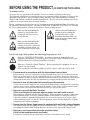
BEFORE USING THE PRODUCT, BE SURE TO READ THE FOLLOWING:
To maintain safety:
To ensure the safe operation of this product, be sure to read the following before usage.
The following instructions are intended for the users, operators and the personnel in charge of the
operation of the product. After carefully reading and sufficiently understanding the warning
displays and cautions, handle the product appropriately. Be sure to keep this manual close to the
product or in a convenient place for future reference.
Herein, explanations which require special attention are enclosed with dual lines. Depending on
the potentially hazardous degrees, the terms of DANGER, WARNING, CAUTION, etc. are used.
Be sure to understand the contents of the displays before reading the text.
Indicates that mishandling the
product by disregarding this
pictograph will cause severe
injury or death.
Indicates that mishandling the
product by disregarding this
caution will cause a slight
hazardous situation which can
result in personal injury and/or
material damage.
Indicates that mishandling the
product by disregarding this
warning will cause a potentially
hazardous situation which can
result in death or serious injury.
For the safe usage of the product, the following pictographs are used:
Indicates "HANDLE WITH CARE." In order to protect the human body and
equipment, this display is attached to places where the Owner's Manual, Serviceman
Manual and/or Service Manual should be referred to.
Indicates a "Protective Earth Terminal." Before operating the equipment, be sure to
connect it to the Ground.
(The step may be omitted for products in which a power cord with earth is used.)
❍ Perform work in accordance with the instructions herein stated.
Instructions for work are explained by paying attention to the aspect of accident prevention.
Failing to perform work as per the instructions can cause accidents. In the case where only
those who have technical expertise should perform the work to avoid hazardous situation, the
instructions herein state that the site maintenance personnel should perform such work.
❍ Be sure to turn off the power before working on the machine.
To prevent an electric shock, be sure to turn off the power before carrying out any work that
requires direct contact with the interior of the product. If the work is to be performed in the
power-on status, the Instruction Manual herein always states to that effect.
❍ Be sure to ground the Earth Terminal.
(This is not required in the case where a power cord with earth is used.)
This product is equipped with the Earth Terminal. When installing the product, connect the
Earth Terminal to the "accurately grounded indoor earth terminal" by using an earth wire.
Unless the product is grounded appropriately, the user can be subject to an electric shock.
After performing repair, etc. for the control equipment, ensure that the Earth Wire is firmly
connected to the control equipment.
❍ Ensure that the Power Supply used is equipped with an Earth Leakage Breaker.
This product does not incorporate the Earth Leakage Breaker. Using a power supply which is
not equipped with the Earth Leakage Breaker can cause a fire when earth leakage occurs.
❍ Be sure to use fuses which meet the specified rating.
(Only for the machines which use fuses.)
Using fuses exceeding the specified rating can cause a fire and an electric shock.
❍ Specification changes (removal of equipment, conversion and addition) not
designated by SEGA are not allowed.
The parts of the product include warning labels for safety, covers for personal protection, etc.
It is very hazardous to operate the product by removing parts and/or modifying the circuits.
Should doors, lids and protective parts be damaged or lost, refrain from operating the product,
and contact where the product was purchased from or the office herein stated.
SEGA shall not be held responsible for any accidents, compensation for damage to a third
party, resulting from the specifications not designated by SEGA.
❍ Ensure that the product meets the requirements of appropriate Electrical
Specifications.
Before installing the product, check for Electrical Specifications. SEGA products have a
nameplate on which Electrical Specifications are described. Ensure that the product is
compatible with the power supply voltage and frequency requirements of the location. Using
any Electrical Specifications different from the designated Specifications can cause a fire and
an electric shock.
❍ Install and operate the product in places where appropriate lighting is
available, allowing warning labels to be clearly read.
To ensure safety for the customers, labels and printed instructions describing potentially
hazardous situations are applied to places where accidents can be caused. Ensure that where
the product is operated has sufficient lighting allowing the warnings to be read. If any label is
peeled off, apply it again immediately. Please place an order with where the product was
purchased from or the office herein stated.
❍ When handling the monitor, be very careful.
(Applies only to the product with a monitor.)
Some of the monitor (TV) parts are subject to high tension voltage. Even after turning off the
power, some portions are still subject to high tension voltage sometimes. Monitor repair and
replacement should be performed only by those technical personnel who have knowledge of
electricity and technical expertise.
❍ Be sure to adjust the monitor/projector properly.
(Applies only to the product with a monitor/projector.)
Do not operate the product leaving on-screen flickering or blurring as it is. Using the product
with the monitor/projector not properly adjusted may cause dizziness or a headache to an
operator, a player, or the customers.
❍ When transporting or reselling this product, be sure to attach this manual to
the product.
In the case where commercially available monitors and printers are used in this product, only
the contents relating to this product are explained herein. Some commercially available
equipment has functions and reactions not stated in this manual. Read this manual together
with the specific Instruction Manual of such equipment.
* Descriptions herein contained may be subject to improvement changes without notice.
* The contents described herein are fully prepared with due care. However, should any
question arise or errors be found, please contact SEGA.
INSPECTIONS IMMEDIATELY AFTER TRANSPORTING THE PRODUCT TO THE LOCATION
Normally, at the time of shipment, SEGA products are in a status allowing for usage immediately
after transporting to the location. Nevertheless, an irregular situation may occur during
transportation. Before turning on the power, check the following points to ensure that the product
has been transported in a satisfactory status.
❐ Are there any dented portions or defects (cuts, etc.) on the external surfaces of the cabinet?
❐ Are Casters and Adjusters damaged?
❐ Do the power supply voltage and frequency requirements meet with those of the location?
❐ Are all wiring connectors correctly and securely connected? Unless connected in the correct
way, connector connections can not be made accurately. Do not insert connectors forcibly.
❐ Do power cords have cuts and dents?
❐ Do the fuses used meet specified ratings? Is the Circuit Protector in an energized status?
❐ Are all accessories available?
❐ Can all Doors and Lids be opened with the Accessory Keys? Can Doors and Lids be firmly
closed?
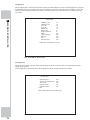
TABLE OF CONTENTS
BEFORE USING THE PRODUCT, BE SURE TO READ THE FOLLOWING:
INTRODUCTION ................................................................................................ iii
1 HANDLING PRECAUTIONS ......................................................................... 1
2 PRECAUTIONS REGARDING INSTALLATION LOCATION........................ 6
2-1 LIMITATIONS OF USAGE ................................................................................................7
2-2 OPERATION AREA ..........................................................................................................8
TABLE OF CONTENTS
TABLE OF CONTENTS ....................................................................................... i
3 PRECAUTIONS REGARDING PRODUCT OPERATION ............................. 9
3-1 BEFORE OPERATION ....................................................................................................9
3-2 DURING OPERATION (PAYING ATTENTION TO CUSTOMERS) ................................12
4 PART DESCRIPTIONS ................................................................................ 16
5 ACCESSORIES ........................................................................................... 18
6 ASSEMBLY AND INSTALLATION .............................................................. 21
7 PRECAUTIONS WHEN MOVING THE MACHINE...................................... 73
8 PROJECTOR ............................................................................................... 78
8-1 CLEANING THE SCREEN ...........................................................................................79
8-2 PROJECTOR ADJUSTMENT .......................................................................................80
8-3 CHANGING THE LAMP UNIT........................................................................................84
9 STEERING WHEEL MECHANISM .............................................................. 91
9-1 VOLUME ADJUSTMENT AND REPLACEMENT ..........................................................92
9-2 GREASING .....................................................................................................................96
10 GEAR SHIFTER........................................................................................... 97
10-1 GEAR SHIFTER REMOVAL.........................................................................................97
10-2 SWITCH REPLACEMENT............................................................................................98
10-3 GREASING ...................................................................................................................98
11 ACCELERATOR & BRAKE......................................................................... 99
11-1 VOLUME ADJUSTMENT AND REPLACEMENT ........................................................99
11-2 GREASING .................................................................................................................102
12 COIN SELECTOR ...................................................................................... 103
E0-0704
420-7004-02
i
13 GREASING THE RIDE MECHANISMS..................................................... 105
13-1 GREASING THE ACTUATOR ....................................................................................106
13-2 GREASING THE GUIDE ............................................................................................ 111
14 FLUORESCENT LIGHT REPLACEMENT ................................................ 115
15 PERIODIC INSPECTION ........................................................................... 119
TABLE OF CONTENTS
16 TROUBLESHOOTING............................................................................... 122
17 GAME BOARD .......................................................................................... 125
17-1 REMOVING THE LINDBERGH ..................................................................................126
17-2 COMPOSITION OF THE GAME BOARD ..................................................................130
17-3 SOFTWARE INSTALLATION .....................................................................................131
18 DESIGN-RELATED PARTS....................................................................... 139
19 WIRE COLOR CODE TABLE .................................................................... 142
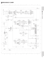
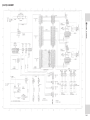
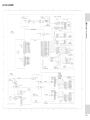
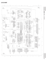
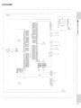
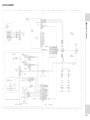
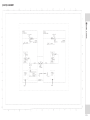
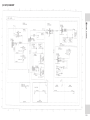
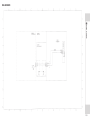
20 WIRING DIAGRAM.................................................................................... 143
ii
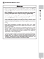
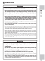
INTRODUCTION
This manual is intended to provide detailed descriptions together with all the necessary information covering the
general operation of electronic assemblies, electro-mechanicals, servicing control, spare parts, etc. for the product,
“OUTRUN 2 SPECIAL TOURS DX
.”
In the unlikely event that the product does not function correctly, DO NOT allow anyone other than a technician
to touch the internal system. Turn off the power to the machine, making sure to unplug the electrical cord from the
RXWOHWDQGFRQWDFWWKHRI¿FHOLVWHGEHORZRUWKHSRLQWRISXUFKDVHIRUWKLVSURGXFW
Use of this product is unlikely to cause physical injuries or damage to property. However, points that require special
attention are indicated by bold text, the word "IMPORTANT" and the symbol below.
TABLE OF CONTENTS
This manual is intended for the owners, personnel and managers in charge of operation of the product.
2SHUDWHWKHSURGXFWDIWHUFDUHIXOO\UHDGLQJDQGVXI¿FLHQWO\XQGHUVWDQGLQJWKHLQVWUXFWLRQV
Indicates important information that, if ignored, may result in the mishandling of
the product and cause faulty operation or damage to the product.
Sega Amusements U.S.A., Inc.
800 Arthur Avenue, Elk Grove Village, IL 60007-5215, U.S.A.
TEL:
1-847-364-9787
TOLL FREE: 1-888-877-2669
FAX:
1-847-427-1065
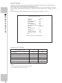
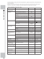
SPECIFICATIONS
Installation space:
4,000 mm (157.5in.) [Width] x 3,200 mm (126.0 in.) [Depth]
Height:
Weight:
2,250 mm (88.6 in.)
1,850 kg (4,078.6 lbs.)
Power, maximum current: [Per cabinet]
Single phase AC 208 V, 4.8 A
NOTE: The contents herein described are subject to change without notice.
iii
'H¿QLWLRQRIµ6LWH0DLQWHQDQFH3HUVRQQHORU2WKHU4XDOL¿HG,QGLYLGXDOV
INTRODUCTION
Procedures not described in this manual or marked as 'to be carried out by site
maintenance personnel or other qualified professionals' should not be carried
out by personnel without the necessary skill or technology. Work carried out by
XQTXDOLÀHGSHUVRQVPD\FDXVHVHULRXVDFFLGHQWVLQFOXGLQJHOHFWURFXWLRQ
Parts replacement, maintenance inspections and troubleshooting should be carried out by site maintenance personnel
RURWKHUTXDOL¿HGSURIHVVLRQDOV7KLVPDQXDOLQFOXGHVGLUHFWLRQVIRUSRWHQWLDOO\GDQJHURXVSURFHGXUHVZKLFKVKRXOG
only be carried out by professionals with the appropriate specialized knowledge.
7KHVLWHPDLQWHQDQFHSHUVRQQHORURWKHUTXDOL¿HGSURIHVVLRQDOVPHQWLRQHGLQWKLVPDQXDODUHGH¿QHGDVIROORZV
Site maintenance personnel:
Individuals with experience in maintaining amusement equipment, vending machines, etc., working under the
supervision of the owner/operator of this product to maintain machines within amusement facilities or similar
premises by carrying out everyday procedures such as assembly, maintenance inspections, and replacement of units/
expendable parts.
Activities to be carried out by site maintenance personnel:
Amusement equipment/vending machine assembly, maintenance inspection and replacement of units/expendable
parts.
2WKHUTXDOL¿HGSURIHVVLRQDOV
Persons employed by amusement equipment manufacturers, or involved in design, production, testing or
maintenance of amusement equipment. The individual should have either graduated from technical school or hold
VLPLODUTXDOL¿FDWLRQVLQHOHFWULFDOHOHFWURQLFVPHFKDQLFDOHQJLQHHULQJ
$FWLYLWLHVWREHFDUULHGRXWE\RWKHUTXDOL¿HGSURIHVVLRQDOV
Amusement equipment/vending machine assembly, repair/adjustment of electrical/electronic/mechanical parts.
iv
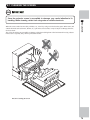
1 HANDLING PRECAUTIONS
When installing or inspecting the machine, be very careful of the following points and pay attention to ensure that
the player can enjoy the game safely.
Non-compliance with the following points or inappropriate handling running counter to the cautionary matters
herein stated can cause personal injury or damage to the machine.
1
• Do not expose power cords or earth wires on the surface, (floor, passage,
etc.). If exposed, the power cords and earth wires are susceptible to damage.
Damaged cords and wires can cause an electric shock or short circuit.
7RDYRLGFDXVLQJDÀUHRUDQHOHFWULFVKRFNGRQRWSXWWKLQJVRQRUGDPDJHWKH
power cords.
HANDLING PRECAUTIONS
• Before performing work, be sure to turn the power off. Performing the work
without turning the power off can cause an electric shock or short circuit. In the
case work should be performed in the status of power on, this manual always
states to that effect.
• When or after installing the product, do not unnecessarily pull the power cord. If
GDPDJHGWKHSRZHUFRUGFDQFDXVHDÀUHRUDQHOHFWULFVKRFN
• In case the power cord is damaged, ask for a replacement through where the
product was purchased from or the office herein stated. Using the cord as is
GDPDJHGFDQFDXVHÀUHDQHOHFWULFVKRFNRUOHDNDJH
• Be sure to perform grounding appropriately. Inappropriate grounding can
cause an electric shock.
• Be sure to use fuses meeting the specified rating. Using fuses exceeding the
VSHFLÀHGUDWLQJFDQFDXVHDÀUHRUDQHOHFWULFVKRFN
• Completely make connector connections for IC BD and others. Insufficient
insertion can cause an electric shock.
6SHFLÀFDWLRQFKDQJHVUHPRYDORIHTXLSPHQWFRQYHUVLRQDQGRUDGGLWLRQQRW
designated by SEGA are not permitted.
)DLOXUHWRREVHUYHWKLVPD\FDXVHDÀUHRUDQHOHFWULFVKRFN1RQFRPSOLDQFH
ZLWKWKLVLQVWUXFWLRQFDQKDYHDEDGLQÁXHQFHXSRQSK\VLFDOFRQGLWLRQVRIWKH
players or the onlookers, or result in injury during play.
- SEGA shall not be held responsible for damage, compensation for damage to
DWKLUGSDUW\FDXVHGE\VSHFLÀFDWLRQFKDQJHVQRWGHVLJQDWHGE\6(*$
• If work or parts replacement not indicated in this manual is carried out, an
accident may occur. If it is necessary to carry out work not indicated in this
PDQXDOEHVXUHWRKDYHLWGRQHE\WKHRIÀFHLQGLFDWHGLQWKLVPDQXDORUE\WKH
SRLQWRISXUFKDVH$OVRSOHDVHLQTXLUHUHJDUGLQJGHWDLOVRIWKHZRUNLQYROYHG
• Be sure to perform periodic maintenance inspections herein stated.
1
• For the IC board circuit inspections, only the logic tester is allowed. The use of a
multiple-purpose tester is not permitted, so be careful in this regard.
1
HANDLING PRECAUTIONS
2
• This product uses a projector. The projector’s screen can be easily damaged so
exercise caution when cleaning it. For details, read the chapter on “Projector.”
• Some parts are not designed and manufactured specifically for this game
PDFKLQH7KHPDQXIDFWXUHUVPD\GLVFRQWLQXHRUFKDQJHWKHVSHFLÀFDWLRQVRI
such general-purpose parts. If this is the case, SEGA cannot repair or replace a
failed game machine whether or not a warranty period has expired.
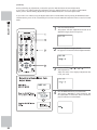
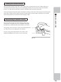
&21&(51,1*:$51,1*',63/$<6
This SEGA product has stickers attached describing
the product manufacture No. (Serial No.) and Electrical
6SHFL¿FDWLRQV,WDOVRKDVD6WLFNHUGHVFULELQJZKHUHWR
contact for repair and for purchasing parts.
When inquiring about or asking for repairs, mention
the Serial No. and Name of Machine indicated on
the Sticker. The Serial Number indicates the product
UHJLVWHU,GHQWLFDOPDFKLQHVFRXOGKDYHGLIIHUHQW
parts depending on the date of production. Also,
LPSURYHPHQWVDQGPRGL¿FDWLRQVPLJKWKDYHEHHQPDGH
DIWHUWKHSXEOLFDWLRQRIWKLVPDQXDO,QRUGHUWRHQVXUH
you order the correct parts, mention the Serial No. when
contacting the applicable places.
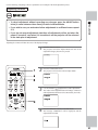
This SEGA product has warning displays on stickers,
labels and/or printed instructions adhered/attached to or
incorporated in the places where a potentially hazardous
situation could arise. The warning displays are intended
for accident prevention for customers and for avoiding
hazardous situations relating to maintenance and
servicing work. Some portions of the cabinet contain
high voltage and may cause accidents if touched. When
performing maintenance, be very careful of the warning
GLVSOD\V,WLVHVSHFLDOO\LPSRUWDQWWKDWDQ\FRPSOH[
repair and replacement work not mentioned herein
should be performed by those technical personnel who
KDYHNQRZOHGJHRIHOHFWULFLW\DQGWHFKQLFDOH[SHUWLVH
,QRUGHUWRSUHYHQWDFFLGHQWVFDXWLRQDQ\FXVWRPHU
ignoring the warnings to cease and desist immediately.
NOTE: The stickers referred to in this manual are all
attached to each machine.
㆑࿈
㆑࿈
វ㞹ࡌࡾ༱㝜࠵ࡽࡱࡌ
ࡡ࡚㸡షᴏ๑࡞ࡢᚪࡍࠈࠈ
㞹″ࢅวࡖ࡙ࡂࡓࡈ࠷㸣
វ㞹ࡌࡾ༱㝜࠵ࡽࡱࡌ
ࡡ࡚㸡షᴏ๑࡞ࡢᚪࡍࠈࠈ
㞹″ࢅวࡖ࡙ࡂࡓࡈ࠷㸣
1
HANDLING PRECAUTIONS
&21&(51,1*7+(67,&.(5',63/$<
ᮇࣗࢼࢴࢹ㈹㔖
㹠㹜
3
1
HANDLING PRECAUTIONS
4
1
HANDLING PRECAUTIONS
5
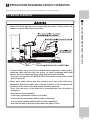
2 PRECAUTIONS REGARDING INSTALLATION LOCATION
2
PRECAUTIONS REGARDING INSTALLATION LOCATION
6
This product is an indoor game machine. Do not install it outside. Even indoors,
avoid installing in places mentioned below so as not to cause a fire, electric
VKRFNLQMXU\DQGRUPDOIXQFWLRQ
- Places subject to rain or water leakage, or places subject to high humidity in
WKHSUR[LPLW\RIDQLQGRRUVZLPPLQJSRRODQGRUVKRZHUHWF
- Places subject to direct sunlight, or places subject to high temperatures in the
proximity of heating units, etc.
3ODFHVÀOOHGZLWKLQÁDPPDEOHJDVRUSODFHVLQWKHYLFLQLW\RIKLJKO\LQÁDPPDEOH
volatile chemicals or hazardous matter.
- Dusty places.
- Sloped surfaces.
- Places subject to any type of violent impact.
3ODFHVLQWKHYLFLQLW\RIDQWLGLVDVWHUIDFLOLWLHVVXFKDVÀUHH[LWVDQGÀUHH[WLQJXLVKHUV
- Areas where the temperature exceeds the applicable temperature (ambient
temperature) range of 5 to 30 degrees centigrade.
2-1 LIMITATIONS OF USAGE
• A dedicated breaker and grounding mechanism are necessary for the control
tower and each cabinet of this product. Failure to heed this warning can cause
DÀUHRUHOHFWULFVKRFN
• Use wires of the following capacity for the indoor power wiring. The use of wires
RIGLIIHUHQWHOHFWULFDOVSHFLÀFDWLRQVFDQFDXVHDÀUHRUHOHFWULFVKRFN
Per cabinet: Single phase AC 208 V, 15 A min.
%HVXUHWRXVHDQLQGHSHQGHQWSRZHUVXSSO\HTXLSSHGZLWKDQHDUWKOHDNDJH
breaker. Using a power supply without an earth leakage breaker can cause an
RXWEUHDNRIÀUHLIDSRZHUVXUJHRFFXUV
• Putting many loads on one electrical outlet can cause generation of heat and a
ÀUHUHVXOWLQJIURPRYHUORDG
• Use cable as rated below for the power cable. Use of a rated cable that does
QRWVDWLVI\WKHSUHVFULEHGUDWLQJFDQFDXVHÀUHDQGHOHFWULFVKRFN
Single phase AC 208 V, 15 A min.
2
PRECAUTIONS REGARDING INSTALLATION LOCATION
• Be sure to check the Electrical Specifications. Ensure that this product
LV FRPSDWLEOH ZLWK WKH ORFDWLRQ
V SRZHU VXSSO\ YROWDJH DQG IUHTXHQF\
UHTXLUHPHQWV $ SODWH GHVFULELQJ (OHFWULFDO 6SHFLILFDWLRQV LV DWWDFKHG WR WKH
SURGXFW 1RQFRPSOLDQFH ZLWK WKH (OHFWULFDO 6SHFLILFDWLRQV FDQ FDXVH D ILUH
and electric shock.
Electricity Consumption:
[Per cabinet]
MAX. 4.8 A (Single phase AC 208 V)
7
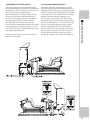
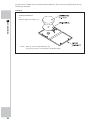
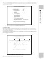
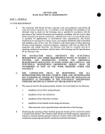
2-2 OPERATION AREA
2
PRECAUTIONS REGARDING INSTALLATION LOCATION
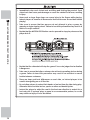
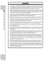
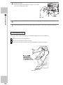
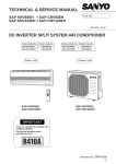
• For the operation of this machine, secure a minimum area of 4.9 m (W) x 4.9 m
(D). These dimensions are necessary to enable the customer to walk around the
PDFKLQHDQGDOVRWRSURYLGH DGHTXDWH YHQWLODWLRQ 7KLV PDFKLQH LV D ULGH VR
there is a possibility of a player falling off. In such an event, if a player strikes his
or her head, a serious accident may occur, so be sure to secure the minimum
DUHDDURXQGWKHPDFKLQHVSHFLÀHGLQWKLVPDQXDO
%HVXUHWRSURYLGHVXIÀFLHQWVSDFHVSHFLÀHGLQWKLVPDQXDO'RQRWDOORZREMHFWV
WREORFNWKHYHQWLODWLRQSRUWV,WFDQFDXVHJHQHUDWLRQRIKHDWDQGDÀUH
• SEGA shall not be held responsible for damage or compensation for damage to
a third party, resulting from the failure to observe this instruction.
,IWKHPDFKLQHGRHVQRWÀWWKURXJKWKHHQWU\ZD\WRWKHLQVWDOODWLRQORFDWLRQGR
QRWGLVDVVHPEOHLWZLWKRXWÀUVWFRQVXOWLQJWKHLQVWUXFWLRQV7KHPDFKLQHVKRXOG
only be disassembled in accordance with the instructions listed in this manual;
GRQRWDWWHPSWWRGLVDVVHPEOHLWLQDQ\RWKHUZD\6SHFLÀFWRROVDQGDGMXVWPHQW
SURFHGXUHVDUHUHTXLUHGWRDVVHPEOHDQGGLVDVVHPEOHWKHPHFKDQLFDOSDUWV
Attempting to assemble or disassemble the machine without consulting the
LQVWUXFWLRQVPD\UHVXOWLQDFFLGHQWVGXULQJDVVHPEO\GLVDVVHPEO\DQGHOHFWULF
VKRFNVKRUWFLUFXLWVDQGRUSHUVRQDOLQMXU\GXULQJRSHUDWLRQ,IWKHPDFKLQHVWLOO
GRHVQRWÀWWKURXJKWKHHQWU\ZD\DIWHUIROORZLQJWKHSURFHGXUHVLQWKLVPDQXDO
FRQWDFW\RXUUHWDLOHURUWKHRIÀFHOLVWHGLQWKLVPDQXDO
• If the machine is still too large to fit through the entryway after following the
procedures listed in this manual, do not tip the machine on its side. Attempting
to transport the machine while it is tipped on its side may cause accidents. It
may also damage or warp parts of the machine, resulting in accidents during
operation.
• To install this product, the entrance must be at least 1.4 m in width and 1.45 m in
height. If the entrance is too narrow, do not tilt the product carelessly. If all the
product weight is put on the casters at one side only, there could be damage
or deformation, causing serious accidents such as workers getting caught
underneath.
វ㞹ࡌࡾ༱㝜࠵ࡽࡱࡌ
ࡡ࡚㸡షᴏ๑࡞ࡢᚪࡍࠈࠈ
㞹″ࢅวࡖ࡙ࡂࡓࡈ࠷㸣
⇍ࡂࡖࡒ⺧ක⅁ࡷ㞹⌣࡞ࡻࡽ
ℾഭࢅࡌࡾ༱㝜࠵ࡽࡱࡌ㸣
ஹᥦ࡞ࡢ༎ฦἸណࡊ࡙ࡂࡓࡈ࠷㸣
㆑࿈
㆑࿈
ᮇࣗࢼࢴࢹ㈹㔖
㹠㹜
វ㞹ࡌࡾ༱㝜࠵ࡽࡱࡌ
ࡡ࡚㸡షᴏ๑࡞ࡢᚪࡍࠈࠈ
㞹″ࢅวࡖ࡙ࡂࡓࡈ࠷㸣
⇍ࡂࡖࡒ⺧ක⅁ࡷ㞹⌣࡞ࡻࡽ
ℾഭࢅࡌࡾ༱㝜࠵ࡽࡱࡌ㸣
ஹᥦ࡞ࡢ༎ฦἸណࡊ࡙ࡂࡓࡈ࠷㸣
㆑࿈
㆑࿈
ᮇࣗࢼࢴࢹ㈹㔖㹠㹜
FIG.2 Operation Area (Unit: mm)
8
3 PRECAUTIONS REGARDING PRODUCT OPERATION
To avoid injury and trouble, be sure to pay attention to the behavior of visitors and players.
3-1 BEFORE OPERATION
3
PRECAUTIONS REGARDING PRODUCT OPERATION
• Check if all of the adjusters are in contact with the surface. If they are not, the
cabinet can move and cause an accident.
• To ensure safety, carry out a trial run before starting operation, and be sure to
FKHFN WKH VDIHW\ GHYLFHV (DFK ULGH PRYHV VR HDFK LV HTXLSSHG ZLWK VDIHW\
devices. Be sure to check that these safety devices function normally.
'RHVWKHULGHVWRSZKHQWKH027,216723EXWWRQDWWKHFHQWHURIWKHFRQWURO
panel is pressed?
• Check each safety device and also check to see if any of the rides move
abnormally. Abnormal motion may cause an accident, so do not operate the
machine until the cause of the abnormality has been removed.
- Does the ride move in the direction corresponding to the direction of
operation?
- Does the ride move smoothly?
- Is there any undesirable looseness in the ride?
- Is any unusual noise emitted while the ride is operating?
- Is any unusual vibration emitted while the ride is operating?
- Does the ride stop at an even position when the game is over?
9
• If an abnormality occurs in the ride mechanism, immediately stop operation,
WXUQRIIWKHSRZHUDQGFRQWDFWWKHRIÀFHLQGLFDWHGLQWKLVPDQXDORUWKHSRLQWRI
purchase. If you continue to operate the machine while there is an abnormality
LQLWDVHULRXVDFFLGHQWVXFKDVDQHOHFWULFVKRFNVKRUWFLUFXLWÀUHRUDIDOOPD\
occur.
3
PRECAUTIONS REGARDING PRODUCT OPERATION
• The motion of the ride will not stop when the ride is touched by anybody other
than a player. Be sure to monitor the machine during a game.
• If a part related to the actuator of the ride mechanism breaks or deforms,
IRU H[DPSOH QHFHVVLWDWLQJ UHSODFHPHQW RU UHSDLU RI WKH SDUW UHTXHVW WKH
RIÀFHLQGLFDWHGLQWKLVPDQXDORUWKHSRLQWRISXUFKDVHWRFDUU\RXWWKLVZRUN
Specialized knowledge, technical expertise, and tools are necessary for
carrying out this work. If you attempt to carry out this work yourself, an accident
may occur.
• Be sure to perform appropriate adjustment of the projector. For operation of this
PDFKLQHGRQRWOHDYHPRQLWRU·VÁLFNHULQJRUGHYLDWLRQDVLV)DLOXUHWRREVHUYH
this can have a bad influence upon the players’ or the customers’ physical
conditions.
• It is suggested to prepare a rest space for players who feel sick after playing the
game.
• Do not put any heavy item on this product. Placing any heavy item on the
product can cause an accident fall or parts damage.
• Do not climb on the product. Climbing on the product can cause an accident
fall. To check the top portion of the product, use a step ladder.
• To avoid electric shock, check to see if door & cover parts are damaged or
omitted.
7R DYRLG HOHFWULF VKRFN VKRUW FLUFXLW DQGRU SDUWV GDPDJH GR QRW SXW WKH
following items on or in the periphery of the product.
)ORZHU YDVHV IORZHUSRWV FXSV ZDWHU WDQNV FRVPHWLFV DQG UHFHSWDFOHV
FRQWDLQHUVYHVVHOVFRQWDLQLQJFKHPLFDOVDQGZDWHU
10
• Inspect for the following items during a trial run. If there is any type of error, use
the Test Mode, etc., to resolve the problem. If you continue use with an error, it
can cause an accident or irreparable parts damage.
- Do the steering wheel and the ride move smoothly during the initialization
operation? (See Chapter 6.)
- Is there any abnormality in the steering wheel reaction mechanism?
- Is there any improper adjustment of the projector screen?
- Are the bellows torn or has a screw dropped out of them?
• During daily cleaning, be sure to check the surface of the steering wheel, gear
shifter, and other parts that the player touches with his hands for damage,
cracks, or loose screws. If a player uses the machine while it is damaged,
cracked, or has a loose screw, the player may become injured.
• During daily cleaning, be sure to check the seat for any abnormality, wetness,
etc. Failure to do this may result in deliberate tampering or negligence being
left undetected.
• Players directly hold the controller with their bare hands so it is recommended
that wet towels (paper towels) be provided.
3
PRECAUTIONS REGARDING PRODUCT OPERATION
- Is there any strangeness in the operability of the steering wheels or the pedals?
(QGHDYRUWRFOHDQWKHVWHHULQJZKHHODQGVHDWIUHTXHQWO\
• Provide a container or space for storing the customers’ hand luggage, etc. To
help prevent an accident and also protect parts, establish measures so that
customers do not bring raingear, such as umbrellas, on rainy days, or juice or
other beverages, into the area where the machine is installed.
• During network play, if communication is interrupted for some reason, each
game will continue independently. Also, if communication is interrupted while in
Customer Welcome Mode, the Test Screen will appear.
• When one cabinet connected for network play enters the Test Mode, the other
cabinets will move to the Test Screen. For this reason, do not needlessly put
a cabinet in the Test Mode while a customer is playing a game, even if the
cabinet is not being used.
<RXFDQPDNHJDPHVHWWLQJVDQGFRLQFUHGLWIHHVHWWLQJVLQGLYLGXDOO\HYHQ
IRU FDELQHWV WKDW DUH FRQQHFWHG IRU QHWZRUN SOD\ <RX FDQ DOVR FKDQJH WKH
settings of an individual cabinet to those for advanced players or beginners, for
H[DPSOH1RUPDOO\KRZHYHUVHWDOORIWKHFDELQHWVWRWKHVDPHVHWWLQJV,I\RX
make a mistake in the fee setting, it is likely that the balance of payments and
other items will be adversely affected.
11
3-2 DURING OPERATION (PAYING ATTENTION TO CUSTOMERS)
,QRUGHUWRSUHYHQWDQDFFLGHQWRUXQQHFHVVDU\WURXEOHWKHDWWHQGDQWRURSHUDWRUPXVWHQGHDYRUWRDOZD\VSD\
attention to the behavior of the players and customer. This machine has movable rides of about the same size as an
DXWRPRELOH6RPHWLPHVDSOD\HURUDFXVWRPHUPD\EHKDYHLQDQXQH[SHFWHGZD\%HDGHTXDWHO\DZDUHRIVDIHW\
and stop any behavior that is considered dangerous.
3
PRECAUTIONS REGARDING PRODUCT OPERATION
• For safety, do not allow any of the following people to play the game.
- Those who have high blood pressure or a heart problem.
- Those who have experienced muscle convulsion or loss of consciousness
when playing video games, etc.
- Those who have neck or spinal cord problems.
7KRVHZKRDUHLQWR[LFDWHGRUXQGHUWKHLQÁXHQFHRIGUXJV
- Pregnant women or those who could be pregnant.
- Those who are not in good health.
- Those who do not follow the attendant’s instructions.
- Those who cannot grasp the Control Unit securely because of immobility in
ÀQJHUVKDQGVRUDUPV
- Persons who disregard the product’s warning displays.
The game cannot be played while sitting in a wheelchair.
• For safety’s sake, a person of less than 140 cm in height cannot play games on
this machine. Because of the dimensions of the seat and the place where the
player puts his or her feet, there is a risk that when the ride moves the player
may fail to support their weight, causing the player to fall off the ride.
• Even players who have never been adversely affected by light stimulus might
experience dizziness or headache depending on their physical condition when
playing the game. Small children are especially likely to experience these
symptoms. Caution guardians of small children to keep watch on their children
during play.
• Instruct those who feel sick during play to have a medical examination.
• To avoid injury from falls and electric shocks due to spilled drinks, instruct the
player not to place heavy items or drinks on the product.
• To avoid electric shocks and short circuits, do not allow customers to put
KDQGVDQGÀQJHUVRUH[WUDQHRXVPDWWHULQWKHRSHQLQJVRIWKHSURGXFWRUVPDOO
openings in or around the doors.
• For safety’s sake, warning indicators such as stickers are placed on the
PDFKLQH+RZHYHUDFDUHOHVVSOD\HUZLOOJHQHUDOO\IDLOWRUHDGWKHVHZDUQLQJV
The attendant must point out steps and level differences on the ride in order to
prevent the occurrence of an accident.
• To avoid falls and resulting injury, immediately stop customers from leaning
against or climbing on the product, etc.
12
1R PRUH WKDQ SHUVRQV VKRXOG VLW RQ HDFK ULGH RI WKLV PDFKLQH ,QVWUXFW
customers that 3 or more players must not sit on a ride. Failure to observe
this precaution may result in players striking their bodies against each other,
causing them to receive blows, fall over, or fall off the ride.
• Entering the cabinet with a wet umbrella or wet shoes is strictly forbidden. There
are electrical parts and wiring underneath the cabinet floor. If these become
wet, this can cause an electric shock or short circuit. Be especially careful in
managing the product on rainy days.
• Take care not to place a heavy object on a ride or seat. This may cause the
object to strike the player when the ride moves.
• Instruct customers not to play a game with a child on their knees. This may
cause an accident such as the child becoming caught between the control
panel and the player or the child falling off the ride.
• Instruct players not to stand during a game in which the ride moves. This may
result in the player falling off the ride or falling over.
• Instruct persons other than players to keep away from the machine while a
game is in progress. If a person touches the moving ride, this may result in an
DFFLGHQWVXFKDVWKHSHUVRQIDOOLQJRYHURUJHWWLQJKLVRUKHUÀQJHUVFDXJKWLQ
the bellows.
3
PRECAUTIONS REGARDING PRODUCT OPERATION
• Instruct customers not to get on or in any ride part, such as the rear of the ride
or behind the back of the seat, other than the seat. Failure to observe this
precaution may results in players falling over, falling off, or catching body parts
in the ride.
• An infant is unable to recognize danger, so instruct the guardian of the infant to
be attentive and ensure that the infant does not approach the machine.
13
• Immediately stop such violent acts as hitting and kicking the product. Such
violent acts can cause parts damage or cause the cabinet to fall over, resulting
in injury.
3
PRECAUTIONS REGARDING PRODUCT OPERATION
• Items such as large finger rings can cause injury to the fingers while playing.
Instruct players to remove all accessories that could cause an accident before
playing.
• Take care to ensure that two persons do not attempt to play a game by
grasping a single steering wheel. Failure to heed this precaution may result in a
minor or a major collision.
([SODLQWKDWWKH027,216723EXWWRQFDQEHSUHVVHGWRVWRSSOD\ZKHQHYHUWKH
player feels ill.
• Explain that the attendant will stop the game if he or she judges that a situation
is dangerous.
• Take care to ensure that other customers do not touch operating devices during
a game. Failure to heed this precaution may result in an accident or cause
trouble between customers.
• There are steps and level differences on each ride, so instruct players to be
careful when getting on or off the ride.
• Do not allow players to extend their hands or feet out from the ride during play.
Otherwise there could be bruises, sprains or other accidental injuries.
• Instruct the player to adjust the seat in the front-rear direction to match his or
her body size. If a player plays a game in an unreasonable posture, he or she
may sustain an injury or incur discomfort.
14
• The load limit on one ride of the machine is 300 kg. If you allow a person or
persons weighing more than the load limit to get on a ride and operate it, the
ride may break down or wear considerably.
• After the end of a game, check to ensure that the player has not forgotten or
dropped any belongings.
3
PRECAUTIONS REGARDING PRODUCT OPERATION
• If a player carries hand luggage or other items onto a ride, objects may fall off
or roll over, for example, when the ride moves, resulting in injury or damage.
Also, instruct players not to take breakable items, etc., onto the ride.
15
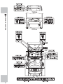
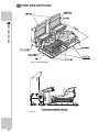
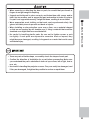
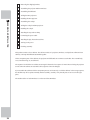
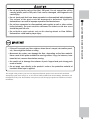
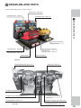
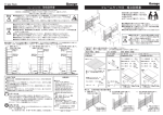
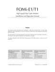
4 PART DESCRIPTIONS
4
PART DESCRIPTIONS
FIG. 4a Overall Diagram
FIG. 4b
16
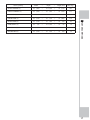
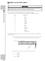
Name (quantity)
×
Depth
×
Height (mm)
Mass (kg)
5($5&$%,1(7
W 1,400
×
D 1,850
×
H 1,170
363
)5217&$%,1(7
W 1,620
×
D
880
×
H 1,250
177
'/3%$6(
W 1,510
×
D
850
×
H
920
152
PROJECTOR (2)
W 1,510
×
D
570
×
H 1,400
110
REAR LAMP (2)
W 1,310
×
D
360
×
H
210
23
6,'(67(3/
W
332
×
D 1,990
×
H
62
18
6,'(67(35
W
332
×
D 1,990
×
H
62
18
%,//%2$5'
W 1,510
×
D
×
H
360
32
630
4
PART DESCRIPTIONS
Width
17
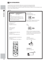
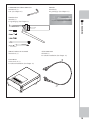
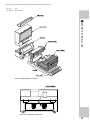
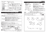
5 ACCESSORIES
&RQ¿UPWKDWWKHDFFHVVRULHVOLVWHGLQWKHWDEOHEHORZDUHSUHVHQWZKHQVHWWLQJXSWKHSURGXFW
Accessories marked "Spare" in the note column are consumable items but included as spares.
,IWKHUHDUHDQLQVXI¿FLHQWQXPEHURIJDPHSOD\PDQXDOVUHTXHVWWKHSRLQWRISXUFKDVHRUWKHRI¿FHLQGLFDWHGLQWKLV
manual to supply additional manuals.
5
TABLE 5a
ACCESSORIES
'(6&5,37,21 2:1(5¶60$18$/
Part No. (Qty.):
420-7004-02 (1)
Note:
This manual
Figures:
Parts not labeled with part numbers are as yet
XQUHJLVWHUHGRUFDQQRWEHUHJLVWHUHG%HVXUHWR
handle all parts with care, as some parts are not
available for purchase separately.
6(59,&(0$18$/
420-7005-01 (1)
([SODQDWLRQRIVRIWZDUH
KEY MASTER
220-5793-2-A001 (2)
For opening/closing the doors
The key master is shipped with the manual
packed together with the accessories.
KEY
(2 each)
PARTS CATALOG
420-7006-02 (1)
Parts list
/,1'%(5*+6(59,&(0$18$/
420-6921-01 (1)
([SODQDWLRQRIEXLOWLQJDPHERDUG
Each key is used for opening and closing the
coin chute door of a seat. The key for each seat
is different. The keys are placed inside the coin
chute doors for shipping.
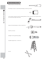
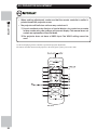
PROJECTOR REMOTE CONTROLLER
200-6023 (2)
For making adjustments. (See Chapter 8.)
92/80(
220-5753/220-5484 (2)
Spare. (See Chapters 9 and 11.)
0,&526:,7&+
509-5704 (2)
Spare. (See Chapter 10.)
18
TAMPERPROOF SCREW WRENCH
540-0007-01 (1)
Tool. (See Chapter 10.)
GREASE
090-0289 (1)
For greasing up. (See Chapter 13.)
*5($6(*81
090-0083 (1)
For greasing up. (See Chapter 13.)
ACCESSORIES
6(59,&(0$18$/'93(1*
420-6923-01 (1)
5
$66<:,5('9'
605-0094 (1)
For software installation. (See Chapter 17.)
'9''5,9(
610-0719-01-91 (1)
For software installation. (See Chapter 17.)
19
7KHSDUWVVKRZQLQ7$%/(EDUHQRWXVHGIRUQRUPDOPDLQWHQDQFH7KH\DUHXVHGWRUHLQVWDOOVRIWZDUHWKDWZDV
inadvertently uninstalled.
TABLE 5b
5
'9'62)7:$5(.,7
(1)
Software media. (See Chapter 17.)
ACCESSORIES
NOTE: When you order the DVD-ROM disc only,
specify the part number 610-0726-0015 (DVD SOFT ORA).
20
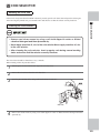
6 ASSEMBLY AND INSTALLATION
• Perform assembly work by following the procedure herein stated. Failure to
comply with the instructions can cause electric shock.
• When assembling, be sure to use plural persons. Depending on the assembly
work, there are some cases in which working by one person alone can cause
personal injury or parts damage.
• Adhere strictly to all of the work procedures stipulated in this document. If two
or more workers are working at the same time, exercise special caution. If
VHTXHQFHVDUHFDUULHGRXWHUURQHRXVO\DFFLGHQWVFDQUHVXOW7KHUHPLJKWDOVR
be cases in which the assembly cannot be completed.
• Pay special attention to the surroundings when a multiple number of workers
are working at the same time. There is always the danger that a worker might
be injured. In assembly and installation of this product, there are procedures in
which a stepladder is used, procedures in which heavy objects are attached,
and procedures involving connection of a rated power supply of 15 amperes.
Carelessness in doing work could lead to grave injuries and even fatalities.
6
ASSEMBLY AND INSTALLATION
• Perform assembling as per this manual. Since this is a complex machine,
LQFRUUHFW DVVHPEOLQJFDQFDXVHDQHOHFWULFVKRFNPDFKLQHGDPDJH DQGRU
LPSURSHUIXQFWLRQLQJDVSHUVSHFLÀHGSHUIRUPDQFH
• Ensure that connectors are accurately connected. Incomplete connections can
cause electric shock.
• This work should be carried out by the site maintenance personnel or other
TXDOLÀHGSURIHVVLRQDOV:RUNSHUIRUPHGE\QRQWHFKQLFDOSHUVRQQHOFDQFDXVH
a severe accident such as electric shock. Failing to comply with this instruction
can cause a severe accident such as electric shock to the player during
RSHUDWLRQ ,I QR RQH ZLWK SURSHU WHFKQRORJLFDO H[SHUWLVH LV DYDLODEOH UHTXHVW
VHUYLFHIURPWKHRIÀFHLQGLFDWHGLQWKLVGRFXPHQWRUWKHSRLQWRISXUFKDVHVRDV
to ensure safety.
• Be careful not to damage the wires. Damaged wires may cause electric shock
RUVKRUWFLUFXLWRUSUHVHQWDULVNRIÀUH
• Do not leave power cable or earth lines exposed over passageways. Exposure
could lead to damage, electric shock or short circuit. Wherever wiring has been
laid out on a floor surface, use a wiring protection cover. (Wiring diameter:
Power cable, approx. Ø18)
3HUVRQV ZKR FRQQHFW LQGRRU SRZHU VXSSOLHV PXVW EH TXDOLILHG HOHFWULFLDQV
'RQRWDOORZDQ\RQHZLWKRXWSURSHUTXDOLÀFDWLRQVWRPDNHVXFKFRQQHFWLRQV
Otherwise there could be electric shock.
21
6
• Provide power cables for connecting the indoor power supply to the product.
Two cables are needed for the cabinets. The rating of each power cable must
EHDWOHDVWDPSHUHV7KHFDEOHVPXVWFRQIRUPWRWKLVUHTXLUHPHQWDQGDOVR
EHRIVXIÀFLHQWOHQJWKWRHQDEOHWKHLQGRRUSRZHUVXSSO\WREHFRQQHFWHGWRWKH
SURGXFWZLWKRXWGLIÀFXOW\8VHRIDFDEOHWKDWGRHVQRWPHHWWKHUHTXLUHPHQWV
FDQUHVXOWLQDÀUHRUHOHFWULFVKRFN
ASSEMBLY AND INSTALLATION
• For the sake of safety and workability, use 3 core coaxial cabtire cables for the
power cables.
• Provide an earth wire for connecting the indoor earth terminal to the product
earth terminal. Unless grounding is secure, there could be electric shock,
damage to parts, or faulty operation.
• When inserting or removing a connector, always hold it by its main part. If you
hold it by anything else while doing so, the connections between wire and
connector terminal fixtures could be damaged; and there could be a short
FLUFXLWRUÀUH
0DNHVXUHWKDWDOOWKHDGMXVWHUVDUHUHVWLQJRQWKHÁRRU7KHFDELQHWPD\PRYH
and cause an accident if the adjusters are not laid out properly.
• Whenever any fasteners (e.g. screws, nuts) have been lost, always use
replacement fasteners with proper dimensions as specified in this document.
,IIDVWHQHUVRIDQ\RWKHUGLPHQVLRQVDUHXVHGLWFRXOGFDXVHGDPDJHDQGRU
separation of parts that result in secondary accidents.
• In order to perform the work of assembling this product reliably and safely,
provide a number of stepladders. If there is only one step ladder, it will be
GLIÀFXOWWRFDUU\RXWWKHZRUN
• Exercise due caution when using stepladders while working. If anyone stumbles
or falls, it could cause a serious accident. In locations where the ceiling is low, a
head injury could occur.
• Be careful when aligning, attaching or mounting parts so that your head, hands,
ÀQJHUVHWFGRQRWJHWFDXJKWLQDQ\WKLQJ,IWZRRUPRUHZRUNHUVDUHZRUNLQJ
at the same time, exercise special caution. Failure to be cautious could result
in accidental bone fractures or amputation. Check the surroundings carefully
before proceeding.
• When connecting wires inside the cabinet, there may be instances in which the
LQGRRUOLJKWLQJGRHVQRWUHDFKWKDWORFDWLRQ+DYHDÁDVKOLJKWRURWKHUDX[LOLDU\
OLJKWLQJHTXLSPHQWRQKDQG,IZLUHVDUHFRQQHFWHGFDUHOHVVO\WKHUHFRXOGEH
DQDFFLGHQWDOVKRUWFLUFXLWÀUHHWF
• After installing the step, be careful. If you trip over the step and fall over, you
may seriously injure yourself.
• When tightening bolts and screws, ensure that other parts are suspended
properly and bolts and screws are fastened tightly. Be sure to take accident
prevention measures such as having another worker support parts. If a part
drops or topples over during this work, a serious accident may result.
22
• When removing or attaching the door or parts, be careful that your hands or
ÀQJHUVGRQRWJHWFDXJKWLQDQ\WKLQJ
6XSSRUWDQGKROGSDUWVLQSODFHVHFXUHO\DQGIDVWHQWKHPZLWKVFUHZVDQGRU
bolts. Use two workers, one to support the part and another to fasten it in place.
If a part is not supported securely, it might fall down, resulting in an accident.
• When installing a wire protection cover over a floor, use a material shaped
so that no one passing by will stumble over it. Using a material that could be
stumbled over might lead to an accidental fall.
• Be careful in handling plastic parts. Be sure not to tighten screws or nuts
too tightly. If such parts are exposed to excessive loads or impact, they
might become damaged, resulting in fragments or cracks that could cause
accidental injury.
6
ASSEMBLY AND INSTALLATION
• Wear appropriate work clothing so that work can be performed safely. Use
gloves and safety shoes to prevent accidents or injuries.
• There are parts of similar shape, so carefully check the shape of each part.
• Confirm the direction of installation for a part before proceeding. Make sure
you understand the part’s orientation in terms of up or down, left or right, front or
rear, etc.
• Be careful in handling the projector screens. They can easily be damaged, and
if they are damaged, it might not be possible to service or repair them.
23
6
ASSEMBLY AND INSTALLATION
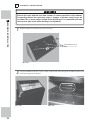
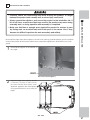
1
Removing the shipping brackets
2
Assembling the projector and the DLP base
3
Assembling the billboard
4
Joining the DLP projectors
5
,QVWDOOLQJWKH'/3SURMHFWRU
6
Assembling the cockpit
7
Joining the cockpit and DLP projector
8
,QVWDOOLQJWKHFRFNSLW
9
Attaching the step and rear lamp
10
Connecting the power cable
11
Attaching the play instructions stickers
12
Turning on the power
13
Checking assembly
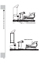
This product consists of two cabinets. The cabinet consists of a projector, DLP base, cockpit (front cabinet and rear
cabinet), rear lamp and billboard assembled together.
2IWKHFRPSRQHQWSDUWVRIWKHFDELQHWVWKHSURMHFWRUVDQGELOOERDUGVDUHFRPPRQWRHDFKRWKHU7KHH[WHUQDOERG\
cover, internal wiring, etc, are different.
The sequence in which the two cabinets are arranged is fastened. The sequence is 1P and 2P seen facing the projector
screens when the cabinets are assembled. This sequence cannot be changed.
,I\RXDVVHPEOHWKHFDELQHWVZLWKWKHFRPSRQHQWSDUWVVHWRXWLQFRUUHFWO\RUZLWKWKHFDELQHWVLQWKHZURQJVHTXHQFH
WKHPDFKLQHPD\IDLOWRRSHUDWHQRUPDOO\%HIRUHDVVHPEO\FDUHIXOO\YHULI\WKDWDOOSDUWVDUHWREHVHWLQWKHULJKW
place.
The number sticker of each DLP base is on the rear of that DLP base.
24
The body color of each cabinet and the rear lamp nameplate are shown below.
1P: Red
2P: Yellow
F50
Dino246GTS
6
ASSEMBLY AND INSTALLATION
FIG. 6a Component parts of cabinet
FIG. 6b No. indication on DLP base
25
Tools necessary for work
- Philips screwdrivers (for M4, M5, and M8)
- Short Philips screwdriver or ratchet handle with Philips screwdriver tip (for M4)
6
ASSEMBLY AND INSTALLATION
6RFNHWZUHQFKHVRUKH[DJRQVFUHZGULYHUVPHDVXULQJGLVWDQFHVRIPPPPDQGPPWRRSSRVLWHVLGHIRU
00DQG0KH[DJRQEROWVDQGQXWV
- Spanner with measuring distance of 24mm to opposite side
24 mm
- Master key (accessory)
- Flashlight or other supplementary lighting
- Stepladder (height must be 1.5 meters min.)
- Scissors
26
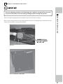
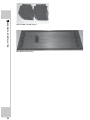
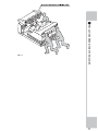
1
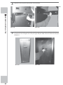
REMOVING THE SHIPPING BRACKETS
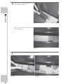
Store the shipping brackets and fastening bolts carefully, because they are used
to prevent the product from becoming damaged while moving the product.
5HPRYHWKHIRXUKH[DJRQEROWVIURPHDFKVKLSSLQJEUDFNHWDQGUHPRYHWKHVKLSSLQJEUDFNHW7KHEUDFNHWXVHVÀDW
washers with bolts that have spring washers attached.
ASSEMBLY AND INSTALLATION
There are red-painted shipping brackets at the bellows at the rear part of the rear cabinets.
6
FIG. 6-1a
FIG. 6-1b SHIPPING BRACKET
27
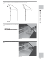
2
6
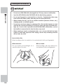
ASSEMBLING THE PROJECTOR AND THE DLP BASE
• Be sure to have at least four persons lift the projector. Do not perform this work
using three or fewer persons. Failure to heed this warning may result in an
accident or injury to a worker.
ASSEMBLY AND INSTALLATION
%H FDUHIXO QRW WR JHW \RXU KDQGV RU ILQJHUV FDXJKW +ROG WKH SURMHFWRU E\ WKH
handles on the side, and also at the bottom part at the rear face. Failure to follow
this precaution may result in broken bones or amputation.
• In addition to the workers who carry the projector, have another worker support
WKH'/3EDVH7KLVZLOOSUHYHQWWKHEDVHIURPPRYLQJDQGFDXVLQJDQDFFLGHQW
2QFH WKH SURMHFWRU KDV EHHQ PRXQWHG RQ WKH '/3 EDVH SURPSWO\ IDVWHQ LW LQ
place. If it is left in an unfastened condition, an unforeseen accident may occur.
The screen of the projector is easily damaged, so try not to touch it during the
above work.
0RXQWWKHSURMHFWRURQWKH'/3EDVH(PSOR\DWRWDORIDWOHDVW¿YHZRUNHUVIRXUIRUFDUU\LQJWKHSURMHFWRUDQGRQH
for supporting the DLP base.
The DLP base has notches to enable the casters on the projector to pass into the DLP base. Mount the projector from
the side of the DLP base that has the notches.
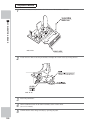
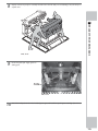
1
Have at least four persons lift the projector, and place it on the DLP base.
FIG. 6-2a
28
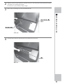
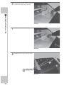
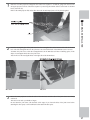
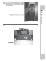
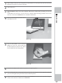
2
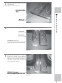
Align the projector and the DLP base so that their sides are in the same plane, and then push them together
so that there is no opening between them.
%HFDUHIXOQRWWRJHW\RXUKDQGVRU¿QJHUVFDXJKW
3
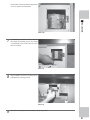
Remove the two fastening screws from the DLP front door.
6
4
ASSEMBLY AND INSTALLATION
FIG. 6-2b
8QORFNWKH'/3IURQWGRRUXVLQJWKHPDVWHUNH\DQGWKHQUHPRYHWKHGRRU
FIG. 6-2c
29
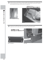
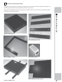
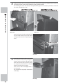
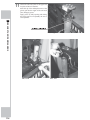
5
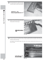
$WWDFKHDFKRIWKHWZRIURQWKROGHUV8VKDSHGUHFWDQJXODUVKHHWPHWDOSDUWVZLWKWZRKH[DJRQEROWVWRWKH
LQVLGHRIWKH'/3IURQWGRRU7KHKROGHUVXVHÀDWZDVKHUVZLWKEROWVWKDWKDYHVSULQJZDVKHUVDWWDFKHG
When attaching the front holder, join the projector to the DLP base.
6
ASSEMBLY AND INSTALLATION
FIG. 6-2d FRONT HOLDER
FIG. 6-2e
6
Attach joint A (L-shaped sheet metal part) to the rear corner of the projector. Fasten each joint A with four
KH[DJRQEROWV-RLQW$XVHÀDWZDVKHUVZLWKEROWVWKDWKDYHVSULQJZDVKHUVDWWDFKHG
FIG. 6-2f JOINT A
30
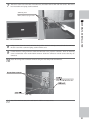
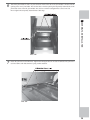
FIG. 6-2g
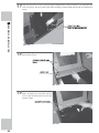
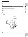
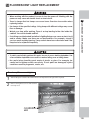
7
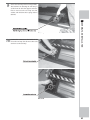
Attach two caster lids on the back of the DLP base, and fasten each of them with four screws. The screws
KDYHÀDWZDVKHUVDQGVSULQJZDVKHUVDWWDFKHG
SCREW (4), black
M4x16, w/flat & spring washers
6
8
9
10
FIG. 6-2i
8VLQJDVFUHZIDVWHQWKHURXQGWHUPLQDODWWKHWLSRIWKHHDUWKZLUHDOUHDG\FRQQHFWHGLQVLGHWKH'/3EDVH
%HVXUHWRXVHDÀDWZDVKHUDQGVSULQJZDVKHUZLWKWKHVFUHZ
ASSEMBLY AND INSTALLATION
FIG. 6-2h CASTER LID
Connect the three wiring connectors inside the DLP base to the projector connectors. There are fastening
VFUHZVRQERWKVLGHVRIWKHPHWDO'68%FRQQHFWRU6HFXUHWKHFRQQHFWRUVZLWKWKHVFUHZVDIWHUWKH\DUH
connected.
Fasten the wiring of the connected connector using the cord clamp inside the DLP base.
FIG. 6-2j
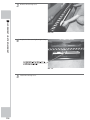
11
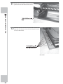
Attach the DLP front door, lock it and fasten it with the two truss screws.
31
3
6
ASSEMBLING THE BILLBOARD
ASSEMBLY AND INSTALLATION
3HUIRUPWKLVZRUNZLWKWKHWRROVDQGQXPEHURIZRUNHUVVSHFLÀHGLQWKLVPDQXDO
Proceeding without the necessary tools or number of workers could cause an
accident. Two or more workers should lift up the billboard, in cooperation with one
other worker who assists while standing on a stepladder.
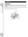
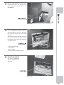
1
Remove the three screws then remove the service door.
TRUSS SCREW (3), black
M4×8
FIG. 6-3a
2
Lift up the billboard with two or more workers. From the rear of the DLP, place the billboard down on the
hook on the upper part of the DLP.
FIG. 6-3b
32
FIG. 6-3c
3
Slide the billboard forward. Hitch the billboard onto the bracket of the DLP.
6
ASSEMBLY AND INSTALLATION
FIG. 6-3d
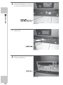
4
)DVWHQWKHELOOERDUGZLWKWZRKH[DJRQEROWV
FIG. 6-3e
5
8QGRWKHFRUGFODPSWRDFFHVVWKHFRQQHFWRU
FIG. 6-3f
33
6
Connect this connector to the connector on
the panel on the upper part of the DLP.
6
ASSEMBLY AND INSTALLATION
FIG. 6-3g
7
Fasten the wire with the cord clamp.
FIG. 6-3h
8
Reattach the service door with three screws.
FIG. 6-3i
34
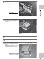
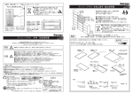
4
JOINING THE DLP PROJECTORS
Arrange the two DLP projectors consisting of the projectors mounted on their DLP bases alongside each other, and
join them together. Attach the following parts between the two projectors.
The parts to be attached between the two projectors are uniform. Note, however, that the wiring connections differ
according to the particular projectors.
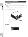
6
ASSEMBLY AND INSTALLATION
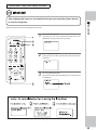
JOINT UPPER (Total 1)
JOINT HOLDER (Total 4)
JOINT MIDDLE (Total 1)
LAN JOINT (Total 1)
JOINT LOWER COVER (Total 1)
JOINT LOWER (Total 1)
35
6
ASSEMBLY AND INSTALLATION
JOINT WIRE COVER (Total 2)
DLP SIDE PLATE (Total 1)
36
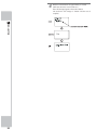
1
Place the two DLP projectors alongside each other. The sequence is 1P and 2P going from the left seen
facing the projector screens. Check the sequence by observing the number stickers at the back of the DLP
EDVHV6HH),*E
Remove the DLP projector lids on the sides where the 1P and 2P projectors will be joined together.
6
2
,QVHUWWKHUHFWDQJXODUSLSHRIWKHMRLQWORZHULQWRWKHUHFWDQJXODUKROHVDWWKHERWWRPRIWKHVLGHRIWKH'/3
base. The side rectangular holes for the joint lower are towards the back of the DLP base (rear of screen).
Assemble the joint lower so that the rectangular holes in the DLP base still have remaining space (in the
shape of a rectangular hole) above the joint lower.
Attach a lid over the rectangular holes in the right side of the 2P DLP base.
FIG. 6-4b
3
ASSEMBLY AND INSTALLATION
FIG. 6-4a
FIG. 6-4c
Move the DLP projector so that the side of the DLP base and the side of the joint lower are firmly
connected.
7DNHFDUHQRWWRFDWFK\RXUKDQGVRU¿QJHUV
'RQRWIDVWHQWKHMRLQWORZHUZLWKWKHEROWVDWWKLVVWDJH,I\RXLQVHUWWKHEROWVRIWKHMRLQWORZHUEHIRUH
DWWDFKLQJWKHRWKHUSDUWVLWZLOOEHGLI¿FXOWWRWKHQDWWDFKWKHRWKHUSDUWV
37
4
7HPSRUDULO\IDVWHQWKHWZRMRLQWKROGHUVWRWKHVLGHRIWKHSURMHFWRUXVLQJWZRKH[DJRQEROWVIRUHDFK7KH
MRLQWKROGHUVXVHÀDWZDVKHUVZLWKEROWVWKDWKDYHVSULQJZDVKHUVDWWDFKHG
The mounting face is the side that faces the adjacent DLP projector. Do not attach joint holders on the left
side of 1P or the right side of 2P.
6
ASSEMBLY AND INSTALLATION
FIG. 6-4d
FIG. 6-4e
,QVHUWWKHMRLQWSDUWLQWRWKHRSHQLQJEHWZHHQ
the joint holder and the projector side. Fasten
DKH[DJRQEROWORRVHO\VRWKHRSHQLQJLVNHSW
intact.
FIG. 6-4f
5
Attach the joint upper in such a way that the
sheet metal on the side of the joint upper is
inserted into the opening of the upper joint
holder. The face that has a notch for passing
the temporarily fastened bolts of the joint
holder is the side of the joint upper.
Also, the face with the rectangular holes is
the screen side.
Do not tighten the temporarily fastened bolts
at this stage.
FIG. 6-4g
38
6
Attach the joint middle in such a way that the sheet metal on the side of the joint middle is inserted into the
opening of the lower joint holder. The face that has a notch for passing the temporarily fastened bolts of the
joint holder is the side of the joint middle. Also, the face with the rectangular holes is the screen side.
Do not tighten the temporarily fastened bolts at this stage.
6
ASSEMBLY AND INSTALLATION
FIG. 6-4h
7
)DVWHQWKHMRLQWORZHUWRWKH'/3EDVH7LJKWHQWKUHHKH[DJRQEROWVRQRQHVLGHRIHDFKVLGH7KHMRLQWORZHU
XVHVÀDWZDVKHUVZLWKEROWVWKDWKDYHVSULQJZDVKHUVDWWDFKHG
FIG. 6-4i
39
8
Tighten all of the temporarily fastened bolts of the joint holder.
6
ASSEMBLY AND INSTALLATION
FIG. 6-4j
9
FIG. 6-4k
Attach the DLP side plate (wooden board). Attach the upper and lower sheet metal parts so that they are
suspended from the rectangular holes in the joint upper and joint middle. Hoist the central sheet metal part
and attach it.
FIG. 6-4l
40
FIG. 6-4m
10
)DVWHQWKH'/3VLGHSODWHXVLQJVL[KH[DJRQEROWV8VHWKUHH
bolts each for the joint upper and middle, respectively. The
MRLQWXSSHUDQGPLGGOHXVHÀDWZDVKHUVZLWKEROWVWKDWKDYH
spring washers attached.
6
11
ASSEMBLY AND INSTALLATION
FIG. 6-4n
Remove the 2 screws fastening the DLP back door at the back of the DLP base. The screws have spring
ZDVKHUVDQGÀDWZDVKHUVDWWDFKHG
FIG. 6-4o
41
12
8QORFNWKH'/3EDFNGRRUZLWKWKHPDVWHU
key, and remove the door. Remove the doors
of all two DLP bases.
6
ASSEMBLY AND INSTALLATION
FIG. 6-4p
13
Connect the LAN cables between the DLP bases. Draw out the LAN cables from the rectangular holes at the
sides of the 1P and 2P. Connect their connectors inside the joint lower.
Also, at this time, draw out the earth wire from the 2P together with the LAN cable.
FIG. 6-4q
Also, use LAN joints to connect the LAN
cables.
FIG. 6-4r
42
14
At the bottom of the joint lower in the area
that is left unpainted, there is a provisionally
fastened screw for securing the earth wire.
Temporarily remove the earth wire fastening
screw, and then use it to secure the round
WHUPLQDOWKDWIDVWHQVWKHHDUWKZLUH%HVXUH
WRXVHDVSULQJZDVKHUDQGDÀDWZDVKHUZLWK
the screw.
6
15
Attach the joint lower cover on the joint
lower. Take care not to damage the wiring.
ASSEMBLY AND INSTALLATION
FIG. 6-4s
FIG. 6-4t
16
Fasten the joint lower cover using two
screws. Each screw has a flat washer and
spring washer attached.
FIG. 6-4u
43
17
Attach the joint wire cover by the left and right rectangular holes of the joint lower cover, and fasten each
ZLWKVHYHQVFUHZV7KHVFUHZVKDYHDÀDWZDVKHUDQGVSULQJZDVKHUDWWDFKHG%HFDUHIXOQRWWRGDPDJHWKH
wiring.
6
ASSEMBLY AND INSTALLATION
FIG. 6-4v
18
Provisionally tighten the center plate on both
sides with two screws.
FIG. 6-4w
19
Pass the keyhole slots of the bracket plate
holder through the provisionally fastened
screws. Push forward until the center hole
becomes visible.
FIG. 6-4x
44
20
Tighten the screw for the center hole.
6
21
Tighten the remaining screws on the both
sides of the bracket plate holder.
ASSEMBLY AND INSTALLATION
FIG. 6-4y
FIG. 6-4z
45
5
INSTALLING THE DLP PROJECTOR
• Carefully check the surrounding area while moving the projector. If you get
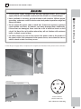
caught between the product and the wall, a serious accident may occur.
6
ASSEMBLY AND INSTALLATION
%HVXUHWRJURXQGWKHDGMXVWHUVDQGVHFXUHWKHSURGXFWÀUPO\WRWKHLQVWDOODWLRQ
location. If the projector moves either during assembly work or during operation
after the completion of assembly, a serious accident may occur.
6HFXUHDGHTXDWHVSDFHDWWKHEDFNRIWKHSURGXFWWRHQDEOHZRUNHUVWRSDVV
E\WKHSURGXFWZLWKRXWSUREOHP$FRQÀQHGVSDFHPD\UHVXOWLQDQDFFLGHQW
during work. It will also prevent work from being carried out accurately and
reliably.
*UDVSWKHKDQGOHVDWWKHVLGHRIWKHSURMHFWRURUWKHVLGHRIWKH'/3EDVHRUKROG
at the bottom, and then either push or pull to move and change direction. Do not
push or hold the sheet metal part because this may result in injury.
• When the adjusters are grounded and secured to the installation location, the
projector cannot be moved easily. Carefully check the distance between
nearby walls and other installed items when grounding the adjusters.
,IWKHÁRRUZKHUHWKHSURMHFWRULVWREHPRYHGLVPDGHRIFDUSHWRUGHFRUDWLYH
sheeting, there is a risk of wear or staining.
(DFK'/3EDVHKDVIRXUFDVWHUVDQGIRXUDGMXVWHUV6HH),*G0RYHWRWKHLQVWDOODWLRQSRVLWLRQGLUHFWO\JURXQG
WKHDGMXVWHUVSURYLGHDQRSHQLQJRIDERXWPPEHWZHHQWKHÀRRUVXUIDFHDQGWKHFDVWHUVDQGSHUIRUPDGMXVWPHQWV
so the machine is level to the ground.
The subsequent assembly work includes placing a ladder at the back of the product and the connecting of power
cables.
%HVXUHWRVHFXUHHQRXJKVSDFHDWWKHEDFNRIWKHSURGXFWWRHQDEOHZRUNHUVWRSDVVE\WKHSURGXFWHDVLO\
46
1
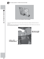
Move the two joined DLP projectors to the installation position. Grasp the handles at the side of the
projector or the side of the DLP base, or hold at the bottom, and then either push or pull to move and change
direction.
6
ASSEMBLY AND INSTALLATION
FIG. 6-5a
2
After moving the DLP projectors to the installation position, check the passageway for customers to ensure
that it has a width of at least 1.2 m, and that there is a clearance of at least 1 m behind the product.
FIG. 6-5b
47
3
Ground all of the adjusters at the bottom of
the DLP base.
6
ASSEMBLY AND INSTALLATION
FIG. 6-5c Ground adjusters
4
Adjust the height of the adjusters. Provide a clearance of about 5 mm between the casters and the floor
surface. After adjustment, tighten the nuts of the adjusters in the upward direction so as to secure the height.
FIG. 6-54d Bottom view of two DLP bases joined together
FIG. 6-5e Adjustment of adjusters
48
6
ASSEMBLING THE COCKPIT
$VVHPEOHWKHWZRFDELQHWV¶FRFNSLWV-RLQWKHIURQWFDELQHWVDQGUHDUFDELQHWVWRJHWKHUDQGFRQQHFWWKHZLULQJ%H
sure that the color of the front cabinet parts matches the body color of the rear cabinet.
6
1
ASSEMBLY AND INSTALLATION
FIG. 6-6a Match the color of the front cabinet and rear cabinet
5HPRYHWKHOHIWDQGULJKWÀRRUVHFWLRQVRIWKH
rear cabinet. Remove three truss screws for
HDFK7KHOHIWDQGULJKWÀRRUVDUHLGHQWLFDO
FIG. 6-6b
2
Join the front cabinet and rear cabinet
together by inserting the two rectangular
SLSHVRIWKHIURQWFDELQHWLQWRWKH8VKDSHG
rectangular hole on the underside of the rear
FDELQHW%HFDUHIXOQRWWRJHW\RXUKDQGVRU
¿QJHUVFDXJKW
FIG. 6-6c
49
3
Fasten the front cabinet and rear cabinet
WRJHWKHUZLWKHLJKWKH[DJRQEROWV8VHIRXU
EROWVLQVLGHHDFKRIWKHOHIWDQGULJKWÀRRUV
Check to ensure that all eight bolts can be
tightened properly before tightening them
IXOO\7KHVHEROWVXVHÀDWDQGVSULQJZDVKHUV
6
ASSEMBLY AND INSTALLATION
FIG. 6-6d
4
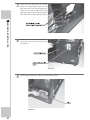
Remove the two truss screws fastening the
motor driver door on the right side of the
front cabinet.
FIG. 6-6e
5
8QORFNXVLQJWKHPDVWHUNH\DQGUHPRYHWKHPRWRUGULYHUGRRU
FIG. 6-6f
50
6
Pass the rear cabinet wiring into the interior of the front cabinet, and connect the two connectors.
6
7
,QVLGHWKHOHIWVLGHÀRRUSXOOWKHIURQWFDELQHWZLULQJWRWKHUHDUFDELQHWDQGFRQQHFWWKHFRQQHFWRU
FIG. 6-6i
8
FIG.6-6h
ASSEMBLY AND INSTALLATION
FIG. 6-6g
FIG. 6-6j
Pass the motor driver wiring (the black
covered wiring with the L and R tags) and
the earth wire to the front cabinet.
FIG. 6-6k
51
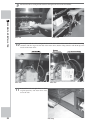
9
Pull the motor driver wiring and the earth wire through to the front of the front cabinet.
6
ASSEMBLY AND INSTALLATION
FIG. 6-6l
10
The two parts with the white casing at the front of the front cabinet is the motor driver. Connect the wiring
connector with the L tag to the near side of the motor driver, and the wiring connector with the R tag to the
far side of the motor driver.
FIG. 6-6n
11
52
FIG. 6-6m
FIG. 6-6o
Reattach the left and right floors to their
original positions, and fasten three truss
screws for each.
FIG. 6-6p
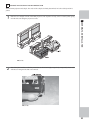
7
JOINING THE COCKPIT AND DLP PROJECTOR
Join each DLP projector and cockpit. The order of the cockpits is already determined. 1P is the red body and 2P is
yellow.
1
Place the two cockpits in front of the DLP projectors. The sequence of body color is red and yellow going
from the left seen facing the projector screens.
6
ASSEMBLY AND INSTALLATION
FIG. 6-7a
2
$WWDFKWKHMRLQWEUDFNHWVVRWKDWWKH\H[WHQGRXWWRWKHOHIWDQGULJKWUHVSHFWLYHO\7HPSRUDULO\IDVWHQHDFK
ZLWKWKHWZRKH[DJRQEROWVWKDWZHUHUHPRYHG
FIG. 6-7b
53
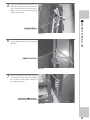
3
Place the cockpit near the DLP projector. As the wiring is
not long, keep the distance between them at around 10 cm.
6
ASSEMBLY AND INSTALLATION
The connector panels are to the front left and right of the
'/3 SURMHFWRU %HVLGHV WKH FRQQHFWRU SDQHO FRQQHFWRUV
there is an earth wire inside the rectangular hole on the left
VLGH,QVLGHWKHUHFWDQJXODUKROHRQWKHULJKWVLGHWKHUHLVD
wire for the yellow connector.
FIG. 6-7d LEFT SIDE CONNECTOR PANEL
4
FIG. 6-7e RIGHT SIDE CONNECTOR PANEL
Remove one screw from the near side motor
driver terminal. The screw uses flat and
VSULQJZDVKHUV%HFDUHIXOQRWWRPLVSODFH
these washers.
FIG. 6-7f
54
FIG. 6-7c
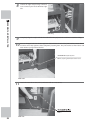
5
Fasten the round terminal of the earth wire
pulled from the DLP projector to the motor
driver terminal with the removed screw.
Make sure to always use flat and spring
washers with the screw.
6
6
Connect the four cockpit wiring connectors
to the connector panel on the left side of the
DLP base.
ASSEMBLY AND INSTALLATION
FIG. 6-7g
FIG. 6-7h
7
Pull out the wiring for the yellow connector
from the inside of the right side rectangular
hole. Connect with the yellow connector of
the cockpit side wiring.
FIG. 6-7i
55
8
Connect the eight cockpit wiring connectors
to the connector panel on the DLP base right
side.
6
ASSEMBLY AND INSTALLATION
FIG. 6-7j
9
10
&RPSOHWHO\DOLJQWKHFRFNSLWZLWKWKHIURQWVLGHRIWKH'/3SURMHFWRU%HFDUHIXOQRWWRFDWFKWKHZLULQJ
3DVVWZRKH[DJRQEROWVLQWRWKH'/3SURMHFWRUVLGHEROWKROHVRIHDFKRIWKHMRLQWEUDFNHWV(QVXUHWKDWDOO
IRXUEROWVFDQEHIXOO\WLJKWHQHGEHIRUHWHPSRUDULO\IDVWHQLQJWKHP7KHMRLQWEUDFNHWVXVHÀDWZDVKHUVZLWK
bolts that have spring washers attached.
HEXAGON BOLT (total 4), black
M8x20, w/spring washer, flat washer used
FIG. 6-7k
11
Attach the motor driver door, lock it, and secure with two truss screws.
FIG. 6-7l
56
8
INSTALLING THE COCKPIT
• Carefully check the surrounding area while moving the product. If caught
between the product and a nearby wall, a serious injury could result.
• Make sure that there is enough space behind the product for workers to pass
by. During work, an accident may result if this space is too narrow. Also, it may
EHFRPHWRRGLIÀFXOWWRSHUIRUPWKHZRUNDFFXUDWHO\DQGUHOLDEO\
(DFKFRFNSLWKDVHLJKWFDVWHUVDQGVL[DGMXVWHUV6HH),*E'LUHFWO\JURXQGWKHDGMXVWHUVSURYLGHDFOHDUDQFH
RIDERXWPPEHWZHHQWKHÀRRUVXUIDFHDQGWKHFDVWHUVDQGSHUIRUPDGMXVWPHQWVVRWKHPDFKLQHLVOHYHOWRWKH
ground.
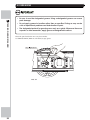
1
Ground all the adjusters on the underside of
the cockpit.
6
ASSEMBLY AND INSTALLATION
• Always ground the adjusters, and secure the product to the installation site. If
this is not done, a serious accident may result as the product may move during
assembly work, or during operation after assembly is completed.
FIG. 6-8a Ground adjusters
2
Adjust the height of the adjusters. Provide
a clearance of about 5 mm between
the casters and the floor surface. After
adjustment, tighten the nuts of the adjusters
in an upward direction so as to secure the
height.
FIG. 6-8b
57
6
ASSEMBLY AND INSTALLATION
58
FIG. 6-8c Adjust the adjusters
3
Fully tighten the four fastening bolts for each of the cockpit joint brackets temporarily fastened to the DLP
projector side.
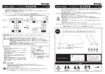
9
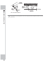
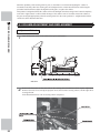
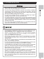
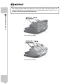
ATTACHING THE STEP AND REAR LAMP
There are two kinds of metal board parts used for the step. These are step side L for use on the left side of the
cockpit, and step side R for use on the right side of the cockpit. First, assemble the step to be attached between the
cockpits.
When attaching the step, the rear lamp is also attached at the same time to the cockpit base rear part. Each rear lamp
is different. Match each rear lamp with the correct cockpit body color before attaching.
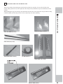
6
ASSEMBLY AND INSTALLATION
STEP HOLDER L (Total 2)
STEP HOLDER R (Total 2)
STEP LID L, R (2 each)
JOINT BRACKET (Total 2)
CUSHIONING (1)
STEP SIDE L, R (2 each)
REAR LAMP (Total 2)
59
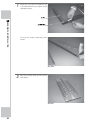
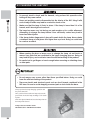
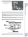
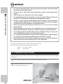
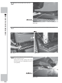
1
Prepare step L and step R. Assemble the step
to be attached between the cockpits. Attach
cushioning to step L.
6
ASSEMBLY AND INSTALLATION
FIG. 6-9a
Cut away any surplus cushioning with a
scissors.
FIG. 6-9b
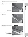
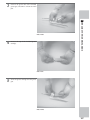
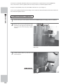
2
Place step L and step R side by side as shown
in the picture.
FIG. 6-9c
60
3
Link step L and step R with the joint bracket
and four screws.
Link the opposite side in the same way.
6
4
3URYLVLRQDOO\IDVWHQVWHSKROGHU/DQGVWHSKROGHU5WRWKHOLQNHGVWHSZLWKIRXUKH[DJRQEROWV
STEP HOLDER R
ASSEMBLY AND INSTALLATION
FIG. 6-9d
STEP HOLDER L
HEXAGON BOLT (2 ea.), black
M8×20, w/spring washer and flat washer used
FIG. 6-9e
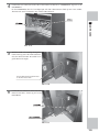
5
,QVHUWWKHOLQNHGVWHSEHWZHHQWKHFRFNSLWV
6HFXUH WR WKH FRFNSLWV ZLWK WZR KH[DJRQ
bolts each. At this time, fully tighten the
bolts that were provisionally fastening the
VWHSKROGHUV8VHÀDWZDVKHUVZLWKEROWVWKDW
have spring washers attached.
FIG. 6-9f
61
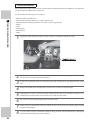
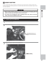
6
Secure the step side L and R in the same
ZD\%RWKVWHSVLGH/DQG5XVHÀDWZDVKHUV
with bolts that have spring washers attached.
6
ASSEMBLY AND INSTALLATION
FIG. 6-9g
7
Remove the rear lamp lids on both sides.
Remove two truss screws from each. The left
and right lids are identical parts.
FIG. 6-9h
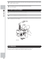
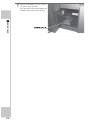
8
$OLJQDUHDUODPSZLWKHDFKFRFNSLWUHDUSDUW$WWKDWWLPHSXOORXWWKHÀXRUHVFHQWOLJKWZLULQJDQGWKHHDUWK
ZLUHIURPWKHKROHLQWKHOHIWUHDUDUHDRIWKHFRFNSLWDQGGUDZWKHPLQWRWKHLQVLGHRIWKHUHDUODPS%H
careful not to catch the wiring.
Pay attention to the nameplate design in the center of the rear lamp. The photo below showing “F50” is for
the 1P rear lamp.
FIG. 6-9i
62
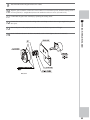
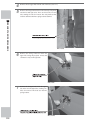
9
6HFXUHWKHUHDUODPSZLWKWZRKH[DJRQEROWV
The bolt hole for fastening the rear lamp is
visible from the hole that appears after the
lids are removed. The rear lamp uses flat
washers with bolts that have spring washers
attached.
6
10
Connect the connector to the inside of the
lid on the rear lamp left side and connect the
earth wire to the rear lamp.
ASSEMBLY AND INSTALLATION
FIG. 6-9j
FIG. 6-9k
63
11
Reattach the removed lids at their original
positions. Secure each with two truss screws.
6
ASSEMBLY AND INSTALLATION
FIG. 6-9l
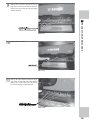
12
Attach the step lid L and R. The slanted side is for the rear
ODPSVLGH8VHQLQHWUXVVVFUHZVIRUHDFKVWHSOLG7KHWUXVV
VFUHZVXVHÀDWZDVKHUV
FIG. 6-9m
64
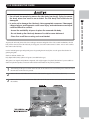
10
CONNECTING THE POWER CABLE
8VHWKHSRZHUVXSSO\HTXLSSHGZLWKDQHDUWKOHDNDJHEUHDNHU 8VHRISRZHU
VXSSO\ZLWKRXWVXFKDEUHDNHUFRXOGUHVXOWLQÀUHLIWKHUHLVDFXUUHQWOHDNDJH
• Do not expose the power cable or earth wire. If these are exposed, customers
could stumble over them, for instance, and easily damage them. Additionally,
if these lines are damaged, there could be a risk of electrical shock or short
circuit. Set these lines at locations where they will not interfere with customer
WUDIÀFRUDWWDFKFRYHUVWRWKHP
• For safety reasons, be sure to first connect the power cable to the product. If
WKHSRZHUFDEOHLVÀUVWFRQQHFWHGWRWKHSRZHUVRXUFHDQDFFLGHQWVXFKDVDQ
electric shock or short circuit may occur.
6
ASSEMBLY AND INSTALLATION
+DYH DYDLODEOH D VHFXUHO\ JURXQGHG LQGRRU HDUWK WHUPLQDO :LWKRXW SURSHU
grounding, customers could be electrocuted and product operations might not
always be stable.
Connect the power supply cables (2 cockpits) to the receptacle (not included) correctly and secure the connection.
POWER CABLE
FIG. 6-10a
L
RECEPTACLE
Hubbell:HBL23
23(for single h
pase)
N
EARTH
6,1*/(3+$6(
+XEEHOO+%/
FIG. 6-10b
FIG. 6-10c Power Cable Plug
65
11
ATTACHING THE PLAY INSTRUCTIONS STICKERS
6
ASSEMBLY AND INSTALLATION
FIG. 6-11a PLAY INSTRUCTIONS STICKERS
$WWDFKDSOD\LQVWUXFWLRQVVWLFNHURQWRSRIHDFKFRFNSLWFRLQFKXWHWRZHU%RWKSOD\LQVWUXFWLRQVVWLFNHUVDUH
identical.
Place the sticker on top of the tower in a visible direction facing the players. Fasten with two screws. The screws
KDYHÀDWDQGVSULQJZDVKHUVDWWDFKHG
FIG. 6-11b
66
12
TURNING ON THE POWER
• Turn on the power only after checking that there are no foreign objects or
abnormalities near the ride’s moving parts or the steering wheel. If any parts are
damaged or deformed due to the presence of a foreign object when the ride
or steering wheel moves during the initialization operation, an accident may
occur.
• Turn on the power, only after reinspecting the assembly work. If the power is
engaged directly after the installation and assembly work is completed, a fatal
accident may occur if the adjusters are not grounded properly, screws are not
fastened, or tools or spare screws have been left on or in the product.
6
ASSEMBLY AND INSTALLATION
• Turn on the power only after carefully checking the surrounding area. The
initialization operation begins automatically when the power is engaged. If a
person is near the product and the ride (car body) or steering wheel moves, that
SHUVRQPD\FROOLGHZLWKWKHSURGXFWDQGDQDFFLGHQWVXFKDVDIDOORUÀQJHUV
being caught may occur.
It will take about five minutes for the Customer Welcome Screen to appear
after the power is engaged and the initialization operation is completed. Do not
touch the ride or steering wheel until the Customer Welcome Screen appears.
The product cannot be operated properly if the initialization operation is not
completed properly. If there is any abnormality when the ride or steering wheel
moves, make sure to reengage the power and conduct the initialization operation
properly.
Take great care when working on this product. This product has a ride the same size as an actual automobile. A
serious accident could occur if proper care is not taken.
Follow the steps below, and then turn on the power. After beginning operation, always be mindful that customers
may leave belongings behind or tamper with the product. Carefully inspect all areas of the product before engaging
power.
1
Reinspect the assembly work, paying special attention to the points below. Finally, check that there are no
persons near the ride.
Has the shipping bracket been removed?
+DYHDOOWKHDGMXVWHUVEHHQSURSHUO\JURXQGHGDQGDUHQRFDVWHUVFRQWDFWLQJWKHÀRRUVXUIDFH"
Have all power cable terminal blocks been fastened correctly?
Has the cover been attached to the terminal block?
Have all fastening bolts and screws been tightened?
Have any foreign objects been placed near the ride, or have any tools or spare screws, etc. been left on or in the
product?
Have any foreign objects been placed near the steering wheel?
67
2
Turn the power switches for each cabinet on the left side of the DLP base on.
Following the order below, output locations will activate.
D 7KHÀXRUHVFHQWOLJKWVRIWKHUHDUODPSDQGWKHELOOERDUGZLOOJORZ
E 7KH/,1'%(5*+ORJRLVGLVSOD\HGRQWKHSURMHFWRUVFUHHQ
c) The steering wheel L initializes. After aligning itself in a center position, it turns completely to the left,
and then returns to the center position.
d) The steering wheel R initializes. After aligning itself in a center position, it turns completely to the left,
and then returns to the center position.
e) The actuator initializes. After moving from its lowest point to its highest point, the actuator stops at its
home position.
f) A network check is performed. The projector screen display changes to a network check display.
J ,IWKHQHWZRUNFKHFNLVFRPSOHWHGSURSHUO\WKH&XVWRPHU:HOFRPH6FUHHQDSSHDUVDQGVRXQGLVRXWSXW
at the same time.
6
ASSEMBLY AND INSTALLATION
3
&KHFNWKDWWKH&XVWRPHU:HOFRPH6FUHHQDSSHDUVRQDOOWKHVFUHHQV,IWKHQHWZRUNFKHFNFRQWLQXHVIRU¿YH
minutes or more, there is most likely a fault in the network play connection or settings.
,IDIWHUWKHLQLWLDOL]DWLRQRSHUDWLRQHQGVWKHVWHHULQJZKHHOLVQRWDWLWVFHQWHUSRVLWLRQIDFLQJVWUDLJKW
DKHDGRUWKHULGHVWRSVDWDWLOWHGSRVLWLRQIRUH[DPSOHUHHQJDJHWKHSRZHUDQGFRQGXFWWKHLQLWLDOL]DWLRQ
operation again.
,IWKHSUREOHPLVQRWFRUUHFWHGDIWHUUHSHDWLQJWKHLQLWLDOL]DWLRQWKHUHLVPRVWOLNHO\DIDXOWLQWKHYROXPH
settings.
Enter Test Mode, and check the settings. (See service manual.)
For this product, the following data and settings are still saved even if the power is turned off. Coin numbers
represented in fractions (number of coins deposited that are not enough for one credit) and bonus adder
count data are not saved.
68
- Number of credits
- Ranking data
7HVW0RGHVHWWLQJVFRLQFUHGLWVHWWLQJVGLI¿FXOW\OHYHOHWF
13
CHECKING ASSEMBLY
8VH7HVW0RGHWRFRQ¿UPWKDWDVVHPEO\KDVEHHQSURSHUO\GRQHDQGWKDWWKH/,1'%(5*+FRQQHFWLQJERDUGVDQG
input/output devices are normal.
Perform the following tests in Test Mode.
)RUWHVWVWRUHIHUWRWKH/,1'%(5*+VHUYLFHPDQXDO)RUWHVWVWRVHHVHUYLFHPDQXDO>*DPH7HVW
Mode].
(1) Information Display Screen
:KHQ³6<67(0,1)250$7,21´³6725$*(,1)250$7,21´RU³-967(67´KDVEHHQVHOHFWHGRQWKH
6\VWHP7HVW0RGH0HQXV\VWHPLQIRUPDWLRQJDPHLQIRUPDWLRQDQGLQIRUPDWLRQRQ-96,2ERDUGFRQQHFWHGWR
/,1'%(5*+DUHGLVSOD\HG
,IHDFKFDWHJRU\RILQIRUPDWLRQLVGLVSOD\HGZLWKRXWDQRPDOLHVWKH/,1'%(5*+LVQRUPDO
6
ASSEMBLY AND INSTALLATION
7KHUHLVD/,1'%(5*+LQVWDOOHGLQHDFKRIWKHWZRFDELQHWVRIWKLVSURGXFW$OZD\V
enter the Test Mode of all two cabinets when checking settings or making
inspections.
When using Test Mode for a particular cabinet, only that cabinet can be checked.
(2) JVS Input Test Screen
:KHQ³,13877(67´KDVEHHQVHOHFWHGRQWKH-96WHVWVFUHHQGDWDLQSXWWRWKH-96,2ERDUGLVGLVSOD\HG2QWKH
product, this is the screen for testing the coin switch.
,QVHUWDFRLQ,IWKHGLVSOD\WRWKHVLGHRIWKHVZLWFKFKDQJHVWKHVZLWFKDQGZLULQJFRQQHFWLRQVDUHQRUPDO
(3) Monitor Test Screen
:KHQ³021,7257(67´KDVEHHQVHOHFWHGRQWKH6\VWHP7HVW0RGH0HQXWKHVFUHHQIRUFKHFNLQJPRQLWRU
adjustment status appears.
Monitor adjustment is completed when the product is shipped from the factory, but you should observe the test
screen to determine whether further adjustment is necessary. Refer to Chapter 8 and adjust the monitor if necessary.
(4) Speaker Test Screen
When “SPEAKER TEST” has been selected on the System Test Mode Menu, the screen for checking speaker sound
output appears.
7RFRQ¿UPWKDWDXGLRRXWSXWLVQRUPDOKDYHWHVWVRXQGRXWSXWIURPWKHJDPHXQLW¶VVSHDNHU
69
(5) Input Test
:KHQ³,13877(67´KDVEHHQVHOHFWHGRQWKH*DPH7HVW0RGH0HQXWKHVFUHHQIRUWHVWLQJLQSXWGHYLFHVDSSHDUV
7HVWWKHLQSXWGHYLFHVE\SUHVVLQJHDFKVZLWFK,IWKHGLVSOD\RQWKHVLGHRIHDFKLQSXWGHYLFHFKDQJHVWR³21´DQG
numerical values change smoothly in accordance with each operation, the input device and its wiring connections
are normal.
INPUT TEST
6
ASSEMBLY AND INSTALLATION
STEERING (1P)
STEERING (2P)
GAS (1P)
GAS (2P)
BRAKE (1P)
BRAKE (2P)
GEAR POSITION
START
VIEW CHANGE
SERVICE
TEST
MOTION STOP
**H
**H
**H
**H
**H
**H
N
OFF
OFF
OFF
OFF
OFF
PRESS TEST AND SERVICE TO EXIT
FIG. 6-13a INPUT TEST Screen
(6) Output Test
:KHQ³2873877(67´KDVEHHQVHOHFWHGRQWKHJDPHWHVWPRGHPHQXWKHVFUHHQIRUWHVWLQJODPSVDQGRWKHU
output devices appears.
,IHDFKRXWSXWGHYLFHRSHUDWHVSURSHUO\WKHRXWSXWGHYLFHDQGLWVZLULQJFRQQHFWLRQVDUHQRUPDO
OUTPUT TEST
START BUTTON
VIEW CHANGE BUTTON
TAIL LAMP
DRIVER LAMP L
DRIVER LAMP R
-> EXIT
OFF
OFF
OFF
OFF
OFF
SELECT WITH SERVICE AND PRESS TEST
FIG. 6-13b OUTPUT TEST Screen
70
:KHQ³$&78$725&21752/%2$5'7(67´KDVEHHQVHOHFWHGWKHVFUHHQIRUWHVWLQJULGHPHFKDQLVPVDSSHDUV
,IZKHQWKHFRQWUROVDUHPDQLSXODWHGWKHULGHPRYHVSURSHUO\DQGLWVWRSVDWLWVOLPLWSRVLWLRQVWKHPHFKDQLVPVDQG
wiring connections are normal.
ACTUATOR CONTROL BOARD TEST
SELECT WITH SERVICE AND PRESS TEST
6
ASSEMBLY AND INSTALLATION
L CW LIMIT SWITCH
OFF
L CCW LIMIT SWITCH
OFF
R CW LIMIT SWITCH
OFF
R CCW LIMIT SWITCH
OFF
L ACTUATOR
***mm
R ACTUATOR
***mm
INITIALIZE
L ACT CW MOVE
L ACT CCW MOVE
R ACT CW MOVE
R ACT CCW MOVE
LR ACT CW MOVE
LR ACT CCW MOVE
L ACT CW R ACT CCW MOVE
L ACT CCW R ACT CW MOVE
ACTUATOR MOVE SPEED
LOW (MID /HIGH)
-> EXIT
FIG. 6-13c ACTUATOR CONTROL BOARD TEST Screen
(7) Calibration Setting
%HJLQDJDPHDQGFKHFNWRVHHLIWKHUHLVDQ\LUUHJXODULW\LQWKHFRQWUROVIRUWKHLQSXWGHYLFHVRULQWKHPRYHPHQW
of the ride. These are adjusted before the product is shipped, but, due to vibration, etc. during transit, there may be a
need to adjust these settings again.
,IWKHFRQWUROVFDQQRWEHRSHUDWHGVDWLVIDFWRULO\VHOHFW³&$/,%5$7,21´RQWKH*DPH7HVW0RGH0HQX6FUHHQDQG
FKHFNDQGDGMXVWWKHYROXPH¿JXUHV
CALIBRATION SETTING MENU
INPUT STEERING VALUE ***
CENTER OF STEER ***
SETTING HANDLE
SETTING CONTENTS
RIGHT
LEFT
-> EXIT
LEFT
CENTER OF STEER
SELECT WITH SERVICE AND PRESS TEST
FIG. 6-13d CALIBRATION SETTING MENU Screen
Also, be sure to conduct the above inspections regularly once a month.
71
(8) Game Assignments
At shipping, the settings for this product are such that coin-operated network play can be conducted on all two
cabinets. Check this setting by entering the Game Setting Screen.
After turning on the power and allowing for the initialization operation to end, check the settings and connection
IRUQHWZRUNSOD\,IWKHVHWWLQJVDQGFRQQHFWLRQDUHQRUPDOWKH&XVWRPHU:HOFRPH6FUHHQZLOODSSHDURQDOOWZR
screens.
,IDOOWZRFDELQHWVFDQFRQGXFWVLPXOWDQHRXVQHWZRUNSOD\SURSHUO\WKHVHWWLQJVDUHQRUPDO
6
ASSEMBLY AND INSTALLATION
GAME ASSIGNMENTS MENU
DIFFICULTY
CABINET
ADVERTISE SOUND
SPEED METER
QUICK START
15 COURSE MODE
DRIVER CHANGE MODE
TIELE TYPE
LINK ID
TOTAL MACHINE
GROUP
VS CAR SELECT
CABINET CAR TYPE
23(5$7,2102'(
-> EXIT
NORMAL
DX
ON
KILO
OFF
OFF
FREE
AMERICA
1
1
1
FIXED
F50
&2,1
SELECT WITH SERVICE AND PRESS TEST
FIG. 6-13e GAME ASSIGNMENTS MENU Screen
[Settings at the time of shipping]
*DPH6HWWLQJ6FUHHQ,WHPV
1P
2P
DX
DX
/,1.,'
1
2
727$/0$&+,1(
2
2
*5283
1
1
),;('
),;('
F50
',12
&2,1
&2,1
&$%,1(7
96&$56(/(&7
&$%,1(7&$57<3(
23(5$7,217<3(
NOTES:
*: This setting must be the same for all two cabinets.
#: This setting is different for each cabinet.
72
7 PRECAUTIONS WHEN MOVING THE MACHINE
• Even when the product is to be moved within the same building, store or facility,
contact the point of purchase or the office indicated in these instructions if
there will be level differences or narrow or low level entrances while moving.
2UUHTXHVWWKDWPRYLQJEHGRQHIRU\RX1HYHUGLVDVVHPEOHWKHSURGXFWLQDQ\
ZD\QRWFRYHUHGLQWKHVHLQVWUXFWLRQV2WKHUZLVHWKHUHFRXOGEHDÀUHHOHFWULF
VKRFNDQGRUVKRUWFLUFXLW
• Always disconnect the power cable before moving the product. If it is moved
ZLWKWKHSRZHUFDEOHFRQQHFWHGWKHFDEOHFRXOGEHGDPDJHGFDXVLQJÀUHRU
electric shock.
$TXDOLÀHGHOHFWULFLDQLVUHTXLUHGIRUPRYLQJSURGXFWSDUWVZLWKLQDVWRUHDQG
for changing indoor wiring. Do not have work performed by anyone who is not
TXDOLÀHG2WKHUZLVHWKHUHFRXOGEHHOHFWULFVKRFN
7
PRECAUTIONS WHEN MOVING THE MACHINE
• As used in these instructions, the term “moving” refers to moving of the product
within the same building, store or facility. These instructions do not cover moving
between different buildings, areas, stores or facilities, since diverse factors are
involved, not only packaging but also loading onto transport vehicles, and
securing the product in place during transport. To transport the product to a
different building or store, contact the vendor where the product was purchased
RUWKHRIÀFHLQGLFDWHGLQWKHVHLQVWUXFWLRQV2UUHTXHVWWKDWPRYLQJEHGRQHIRU
you. This product is made up of parts that are of large size and heavy weight.
Unless work is entrusted to someone with expertise in packaging and transport
of such parts, a serious accident might occur.
+DYH ZRUN SHUIRUPHG E\ VLWH PDLQWHQDQFH SHUVRQQHO RU RWKHU TXDOLILHG
individuals. Do not allow people without proper knowledge and technical
expertise to work on the product. Otherwise there could be an electric shock
or other serious accident. Also, customers could be injured while operating the
product.
1HYHUPRYHWKHSURGXFWDIWHULWKDVEHHQDVVHPEOHG$OZD\VVHSDUDWHWKHWZR
FDELQHWV·FRFNSLWXQLWVIURPWKH'/3VZLWKWKHSURMHFWRUUHPDLQLQJRQWKH'/3
base). Moving the product while it is assembled may cause abnormalities in the
joints and fastenings, and can result in accidents such as electric shock, short
FLUFXLWDQGÀUH
%HFDXVHLWLVVWUXFWXUDOO\GLIÀFXOWIRUH[WHULRUOLJKWLQJWRHQWHUWKHFDELQHWKDYH
auxiliary lighting available. Working within a dark environment can lead to
accidents.
• For instructions on separation and disassembly of the cabinet, please refer to
Chapter 6 of this manual. Failure to follow the instructions given by this manual
leaves a high risk of accidents such as electric shock occurring.
• Proceed with checks and tasks as indicated in these instructions. If instructions
DUHQRWIROORZHGRULIWDVNVDQGRUFKHFNVDUHQHJOHFWHGDQHOHFWULFVKRFNRU
other very serious accident, even fatal accident, can occur. Also, customers
could be injured while operating the product.
73
• Be careful not to damage wiring. Before separating parts that have wiring
connections, disconnect the wiring connections, unravel wire bundles and
undo fastenings. Only after that, remove fasteners (screws, nuts, etc.). If wiring
EHFRPHVGDPDJHGWKHUHFRXOGEHDQHOHFWULFVKRFNVKRUWFLUFXLWRUÀUH
7
PRECAUTIONS WHEN MOVING THE MACHINE
• When inserting or removing a connector, always hold it by its main part. If you
hold it by anything else while doing so, the connections between wire and
connector terminal fixtures could be damaged; and there could be a short
FLUFXLWRUÀUH7KHUHFRXOGDOVREHSRRUFRQQHFWLYLW\
• Do not move unit with the adjusters in contact with the floor. Otherwise parts
might be damaged or deformed and there might be accidents.
• Whenever any fasteners (e.g. screws, nuts) have been lost, always use
replacement fasteners with proper dimensions as specified in this manual. If
IDVWHQHUV RI DQ\ RWKHU GLPHQVLRQV DUH XVHG LW FRXOG FDXVH GDPDJH DQGRU
separation of parts that result in secondary accidents.
• Check surroundings carefully while moving the unit. If you should get caught
between the unit and a wall, for instance, there could be a serious accident.
'RQRWSODFHWKHFRFNSLWRU'/3RQLQFOLQHVRUXQHYHQVXUIDFHV7KLVFRXOGUHVXOW
in the unit falling over.
+DYHRQKDQGDQXPEHURIZRUNHUVDSSURSULDWHIRUHDFKWDVNWKDWQHHGVWREH
done. Make calculations by approximating that one worker can lift roughly 15
kg of weight.
If an insufficient number of workers try to lift a heavy object, it could result
in a worker stumbling and the object being dropped, crushing someone or
something underneath. Workers could also injure their backs, etc.
• When lifting a heavy object, be sure to carefully consider the area where it
will be lifted. If possible, lift the object by its handles or base. If weak fasteners
or fragile parts are gripped, they could be damaged under the weight of
the object, and this could result in a worker stumbling and the object being
dropped, causing personal injury.
1HYHUGLVDVVHPEOHWKHXQLWLQZD\VRWKHUWKDQWKRVHGHVFULEHGLQWKLVPDQXDO
'RLQJVRFDQFDXVHDFFLGHQWVVXFKDVHOHFWULFVKRFNVVKRUWFLUFXLWVDQGÀUHV
'RQRWDWWHPSWWRWLOWWKHXQLWWRÀWLWWKURXJKQDUURZGRRUZD\V0RYLQJWKHXQLW
while it is tilted can result in an accident. It can also cause deformations and
damage to parts, as well as deviations of fastening positions, which could result
in accidents during operation.
74
'R QRW SXVK SODVWLF SDUWV RU WKH ULGH·V )53 SDUWV 'R QRW VXSSRUW WKH XQLW E\
FDUU\LQJSODVWLFSDUWVRU)53SDUWV3DUWVFDQEHGDPDJHGDQGIUDJPHQWVFDQ
cause injury.
• Do not lean separated or disassembled parts against a wall or other surface
indiscriminately. The parts could be deformed. Accidents could also occur
should the parts fall over.
• Do not hold or push controls such as the steering wheels or Gear Shifters.
Deformations could lead to player injury.
,IWKHXQLWLVPRYHGRYHUÁRRUVXUIDFHVZKHUHWKHUHLVFDUSHWGHFRUDWLYHSDQHO
etc., there might be friction or soiling.
0RYHPHQWE\FDVWHUVFDQGDPDJHWKHÁRRUGHSHQGLQJRQWKHÁRRUPDWHULDO
+DYHDPDWRUWKLQSODWHDYDLODEOHIRUPRYLQJFDVWHUV,IUXJVIRULQVWDQFHKDYH
been laid out, remove them before moving.
7
PRECAUTIONS WHEN MOVING THE MACHINE
• Do not stack parts that have been separated or disassembled indiscriminately.
The surface of the parts could be damaged or deformed. Significant
deformations can result in improper operation and breakdowns.
• Be careful not to damage the surfaces of parts. Support and push strong parts
made of metal.
• Do not apply rope directly to the product’s surface. Use protective material at
locations where rope is applied.
7KHVWUHQJWKRIWKLVSURGXFW¶VMRLQWVZHUHQRWGHVLJQHGVXFKWKDWWKHSURGXFWFDQEHPRYHGZKLOHDVVHPEOHG
Attempting to push on the cockpit, etc. to move the unit while assembled can result in damage, deformation, and
misalignment of the joints. Abnormalities in the joints can result in improper operation or breakdown in internal
mechanisms.
75
7
PRECAUTIONS WHEN MOVING THE MACHINE
76
FIG. 7a
FIG. 7b
7
PRECAUTIONS WHEN MOVING THE MACHINE
FIG. 7c
77
8 PROJECTOR
The projector is adjusted prior to leaving the factory. Avoid any unnecessary
adjustment.
8
PROJECTOR
• If the adjustment method in this manual does not resolve the problem contact
the customer service number in this manual or your supplier.
• “Snow” on the screen and changes in brightness for a short period are due to
the high pressure mercury lamp in the projector. This is not a defect and does
not need repairs.
• There is no way of knowing when the lamp is going to cease to function. Once
it ceases to function, the projector will be unable to display anything and the
SURGXFWFDQQRWEHXVHG+DYHDVSDUHODPSUHDG\DWDOOWLPHV
• Do not stick tape, stickers or anything else onto the screen. Any kind of
adhesive may damage the surface of the screen.
The projector can save adjustments.
:KHQWKHWHVWVFUHHQVKRZVGLVWRUWLRQVXVHWKHUHPRWHFRQWUROOHUWRDGMXVWWKHSURMHFWRU¶VVHWWLQJV
7KHSURMHFWRU¶VKLJKSUHVVXUHPHUFXU\ODPSKDVDQDYHUDJHOLIHVSDQRIURXJKO\KRXUVVXUYLYDOUDWHEXW
the actual lifespan may vary depending on its usage.
7KHODPSLVDUHSODFHDEOHSURGXFW,IWKHVFUHHQEHFRPHVGDUNRUJRHVRXWRFFDVLRQDOO\UHSODFHWKHODPSDVTXLFNO\
as possible.
Replace the lamp following the instructions in the instruction manual provided with the projector. Also, be sure to
reset the timer setting.
78
8-1 CLEANING THE SCREEN
Since the projector screen is susceptible to damage, pay careful attention to its
handling. When cleaning, refrain from using water or volatile chemicals.
PROJECTOR
When the screen surface becomes dirty with dust, etc., clean it by using a soft cloth such as gauze. When water, and
volatile chemicals such as benzene, thinner, etc., spill on the screen surface, it may be subject to damage, therefore,
do not use them.
Also, since the surfaces are susceptible to damage, refrain from rubbing them with a hard material or using a duster.
,IWKHVFUHHQLVHVSHFLDOO\GLUW\FDOOLQDSURIHVVLRQDOFOHDQHU
8
FIG. 8-1 Cleaning the screen
79
8-2 PROJECTOR ADJUSTMENT
8
• When making adjustments, make sure that the remote controller’s emitter is
pointed toward the projector screen.
PROJECTOR
• The projector unit itself does not have any controls on it.
*1 Do not needlessly enter Service or Special Modes. Any control errors made
in these modes may alter settings and prevent display. This manual does not
contain an explanation of Service Mode.
*2 The projector does not have a VIDEO input. The VIDEO setting cannot be
used.
8VHWKHDFFRPSDQ\LQJUHPRWHFRQWUROOHUWRSHUIRUPDOOSURMHFWRUDGMXVWPHQWV
7KHUHPRWHFRQWUROOHUFDQQRWWXUQWKHSURMHFWRURUWKHHQWLUHJDPHV\VWHP¶VSRZHU21RU2))
FIG. 8-2a
80
$'-867$GMXVW0RGH
3UHVVWKLVEXWWRQWRHQWHU$GMXVW0RGH,WDOVRIXQFWLRQVDVWKH
(;,7EXWWRQ
(2)
:%VZLWFKZKLWHEDODQFH
6HOHFW:KLWH%DODQFH0RGH
(3)
:5,7,1*PHPRU\
Store adjustment data.
(4)
5*%FRORUVHOHFW
8VHWRVHOHFWDFRORUZKHQDGMXVWLQJFRORUEDODQFH
(5)
CONTRAST:
Adjust the contrast of the projected image.
(6)
%5,*+7
Adjust the black level (brightness) of the projected image.
(7)
TP (test pattern):
Display an internal test pattern.
(8)
PHASE (phase adjust):
Adjust the sampling phase.
(9)
CLOCK (clock adjust):
Adjust the sampling clock.
(10) 326,GLVSOD\SRVLWLRQ
Adjust the display position of the projected image.
(11) &$3785(DGMXVWLPDJHFDSWXUH
Adjust timing of image capture.
(12) 9,'(2LQSXW
Select video input.
(13) 5*%LQSXW
6HOHFW5*%LQSXW
(14) '9,LQSXW
6HOHFW'9,LQSXW
(15) 6(59,&(
Enter Service Mode.
(16) &872))DGMXVWFXWRII
Adjust the white balance of dark areas.
8
PROJECTOR
(1)
(17) $'-867DGMXVWXSGRZQDQGOHIWULJKW Adjusted selected category.
(18) 63(&,$/
Enter Special Mode.
(19) '5,9(DGMXVWGULYH
Adjust the white balance of light areas.
Control and Adjustment
The projector is precisely adjusted in the factory prior to sale. Avoid unnecessary
DGMXVWPHQWDWDOOFRVWV1HHGOHVVO\DOWHULQJDGMXVWPHQWGDWDPD\PDNHDQ\ODWHU
repairs harder to perform.
81
[Controls]
%HIRUHSHUIRUPLQJDQ\DGMXVWPHQWV\RXPXVW¿UVWSUHVVWKH$'-867EXWWRQDQGHQWHU$GMXVW0RGH
,I\RXZLVKWRH[LWZLWKRXWPDNLQJDQ\DGMXVWPHQWVSUHVVWKH$'-867EXWWRQWZLFHWRUHWXUQWR1RUPDO0RGH
:KHQ\RXKDYH¿QLVKHGPDNLQJDGMXVWPHQWVSUHVVWKH:5,7,1*EXWWRQWRUHFRUGWKHDGMXVWHGGDWD
,I\RXZLVKWRH[LWZLWKRXWVDYLQJWKHDGMXVWHGGDWDUHWXUQWR1RUPDO0RGHZLWKRXWSUHVVLQJWKH:5,7,1*EXWWRQ
DQGWKHQWXUQWKHSRZHURIIIRUDUHDVRQDEOHSHULRGRIWLPH3UHVVWKH$'-867EXWWRQWKUHHWLPHVWRUHWXUQWR1RUPDO
Mode.
8
PROJECTOR
82
1
3UHVVWKH$'-867EXWWRQ
The projector will enter Adjust Mode and wait for an
adjustment category button to be pressed.
2
Press an adjustment category button.
The projector will enter the selected Adjustment Mode.
3
8VHWKH$'-867> ] [ ] [ ] [ ] buttons to
make adjustments.
Adjust the values of the displayed adjustment data
to suit your needs.
4
3UHVVWKH:5,7,1*EXWWRQUHFRUGDQG¿QLVK
7KHPHVVDJH³:5,7,1*´ZLOOEHGLVSOD\HGDQG
the adjusted data recorded. After about 3 seconds the
projector will return to Normal Mode.
8VHWKHIROORZLQJ³$GMXVWLQJ&RQWUDVW´H[SODQDWLRQDVDQH[DPSOHRIWKHPDLQDGMXVWPHQWSURFHVV
Adjusting Contrast
• If you wish to carry on and make further adjustments to a different menu repeat
2~3.
• If you do not record adjustment data then all adjustments will be lost when the
power if turned off, and when it is turned back on the projector will be returned
to the state prior to adjustment.
8
PROJECTOR
• To abort adjustment without recording any changes press the ADJUST button
WZLFHLQVRPHLQVWDQFHVWKUHHWLPHVWRUHWXUQWR1RUPDO0RGH
Adjusting the contrast will alter the tones of the displayed image.
1
3UHVVWKH$'-867EXWWRQ
The projector will enter Adjust Mode and wait for an
adjustment category button to be pressed.
2
Press the CONTRAST button.
The projector will enter the Contrast Adjust Mode.
3
8VHWKH$'-867> ] [ ] buttons to make adjustments.
The values of the adjustment data will change. Continue to
PDNHDGMXVWPHQWVXQWLOWKHVFUHHQ¶VFRQWUDFWVXLWV\RXUQHHGV
4
3UHVVWKH:5,7,1*EXWWRQUHFRUGDQG¿QLVK
7KH PHVVDJH ³:5,7,1*´ ZLOO EH GLVSOD\HG DQG WKH
adjusted data recorded.
83
8-3 CHANGING THE LAMP UNIT
• To prevent electric shock and fire hazards, only perform this operation after
turning off the power switch.
8
PROJECTOR
1HYHUSXWDQ\WKLQJPHWDORUÁDPPDEOHLQWRWKHLQWHULRURIWKH'/38VLQJLWZLWK
VXFKDQREMHFWLQVLGHPD\OHDGWRDQHOHFWULFVKRFNRUÀUH
• Make sure that the lamp is firmly in place. If the lamp is loose then it is a fire
hazard, and it also might not come on.
• The lamp becomes very hot during use and remains so for a while afterward.
Attempting to change the lamp before it has sufficiently cooled may lead to
burns and other injuries.
,IWKHODPSVKDWWHUVIUDJPHQWVRIJODVVZLOOUHPDLQLQVLGHWKHODPS1HYHUVKDNH
DVKDWWHUHGODPSRUKROGSODFHRQHKLJKHUWKDQH\HOHYHO'RLQJVRFRXOGOHDG
to a serious accident.
• When opening the door or lamp cover to change the lamp, do not touch or
remove any parts that are unrelated to the lamp changing process. Doing so
PD\OHDGWRLQMXU\DQGFRXOGDOVRKDUPWKHHIÀFLHQWZRUNLQJRIWKHSURGXFW
%HFDUHIXOQRWWRJHWÀQJHUVRUKDQGVFDXJKWZKHQUHPRYLQJRUDWWDFKLQJGRRUV
or other parts.
• Do not remove any screws other than those specified below. Doing so could
KDUPWKHHIÀFLHQWZRUNLQJRIWKHSURGXFW
• There are electric and electronic parts such as circuit boards contained in the
'/3EDVH%HVXUHWRDYRLGGURSSLQJUHPRYHGSDUWVRUWRROVLQVLGHWKHEDVH
Always perform the lamp changing operation with
the power turned off.
Once you have inserted the new lamp only turn the
SRZHUEDFNRQRQFHWKHODPSH[FKDQJHFRYHULVEDFN
in place.
Then enter Special Mode and reset the lamp timer on
the Lamp Timer Screen.
Lamp Unit Parts Number/Name
200-6020/ASSY LAMP DLP PJTN DSPL
84
1
2
7XUQWKHSRZHURIIIRUWKHFDELQHWZKRVHSURMHFWRU¶VODPSZLOOEHFKDQJHG
Remove the DLP front door. Remove the two
truss screws that fasten the door.
8
PROJECTOR
FIG. 8-3a
3
8QORFNXVLQJWKHPDVWHUNH\DQGUHPRYHWKH
DLP front door.
FIG. 8-3b
4
Remove the front beam from the top of the
'/3IURQWGRRUDWWDFKPHQW¿[WXUH5HPRYH
WZRWUXVVVFUHZVDQGWZRÀDWKHDGVFUHZV
FIG. 8-3c
85
5
5HPRYH WKH IURQW EHDP %H FDUHIXO QRW WR
drop it inside the DLP base.
8
PROJECTOR
FIG. 8-3d
There is a lamp replacement cover in the
front of the projector.
FIG. 8-3e
6
Remove four screws, and remove the lamp replacement cover.
FIG. 8-3f
86
FIG. 8-3g
On the inside of the removed lamp replacement
cover are replacement instructions.
8
PROJECTOR
FIG. 8-3h
7
8VHDÀDWKHDGVFUHZGULYHUWRIXOO\ORRVHQWKH
three lamp unit fastening screws. The design
is such that the screws will not be lost even if
they are loosened.
FIG. 8-3i
8
Grip the handle, and remove the lamp unit by
pulling directly towards yourself.
FIG. 8-3j
9
$WWDFKWKHQHZODPSXQLW,QVHUWLWXQWLOLWLVDOOWKHZD\LQVLGH
87
8
PROJECTOR
88
10
11
12
13
Tighten the three lamp unit fastening screws.
Attach the lamp replacement cover, and fasten its four screws.
Attach the front beam.
Attach the DLP front door, and lock it. Fasten the two truss screws.
Special Mode: Lamp Timer Display and Reset
After changing the lamp you must perform the lamp reset operation (step 4 below)
to reset the lamp timer.
1
3UHVVWKH$'-867EXWWRQ
The projector will enter Adjust Mode and wait for an
adjustment category button to be pressed.
2
3UHVVWKH63(&,$/EXWWRQ
The projector will enter Special Mode and await further
selections.
3
3UHVVWKH:5,7,1*EXWWRQ
The amount of time the current lamp has been used for will
be displayed.
PROJECTOR
Displays the amount of time the lamp has been used for.
8
89
4
8
PROJECTOR
90
+ROGGRZQWKH3EXWWRQIRUDSSUR[LPDWHO\VHFRQGV
:LOOUHVHWWKHWLPHUUHFRUGLWDQGH[LW
Once this message appears release the P button.
The used time will change to “00000” and the reset is
complete.
9 STEERING WHEEL MECHANISM
• When working with the product, be sure to turn the power off. Working with the
power on may cause an electric shock or short circuit.
• Do not touch any parts that are not specified in these directions. Touching
XQVSHFLÀHGORFDWLRQVPD\OHDGWRHOHFWULFVKRFNRUFDXVHVKRUWFLUFXLWV
• This work should be performed by site maintenance personnel or other skilled
professionals. Work performed by non-technical personnel can cause a severe
accident such as an electric shock.
• To prevent accidents while working or while operating the product after it
has been installed, be sure not to conduct any procedures other than those
given in this manual. There are cases in which procedures not covered in this
PDQXDOUHTXLUHVSHFLDOWRROVDQGVNLOOV,IDSURFHGXUHQRWJLYHQLQWKLVPDQXDOLV
UHTXLUHGUHTXHVWVHUYLFHIURPWKHRIÀFHJLYHQLQWKLVPDQXDORUIURPWKHSRLQWRI
purchase.
9
STEERING WHEEL MECHANISM
• Be careful not to damage the wires. Damaged wires may cause an electric
VKRFNVKRUWFLUFXLWRUSUHVHQWDULVNRIÀUH
• Exercise due caution in performing soldering procedures. If the soldering iron is
KDQGOHGFDUHOHVVO\WKHUHFRXOGEHÀUHVRUEXUQV
• Proceed very carefully when heating the thermal contraction tube. Careless
RSHUDWLRQVFDQUHVXOWLQÀUHVRUEXUQV
• The motor parts may be hot immediately after a game has been completed, so
allow some time to pass before beginning work on the parts.
• Stand back from the cabinet when restoring power after maintenance has been
completed. The ride and steering wheel will automatically undergo initialization
operation when power is restored. Failure to move away from the product could
result in an accident such as a collision or fall.
• Be careful when handling the parts of the steering wheel mechanism. Avoid
damaging, deforming, or losing them. The loss of even one part will adversely
affect the operation of the steering wheel, and may cause player injury. It could
also result in fatal breakdown or faulty operations.
• Be careful not to get fingers caught when removing or attaching doors or
DGMXVWLQJWKH95EUDFNHW
• The handle mechanism has mechanical parts such as gears and timing belts.
3HUIRUPLQJ PDLQWHQDQFH DOVR UHTXLUHV D SHUVRQ WR EHQG RYHU WKH VLGH RI WKH
cockpit. Careless work methods can result in injuries such as back and shoulder
LQMXULHVRUÀQJHUVEHLQJFDXJKW
91
When the operability of the steering wheel is poor, or when there is no effect from adjusting the volume in
Test Mode, most likely either the volume gears are misaligned or the volume has broken down. Following the
procedures described below, adjust the alignment of the gears, or replace the volume.
This product is designed such that the volume will not be damaged when the steering wheel is turned completely
WRWKHOHIWRUULJKWEHFDXVHLWZLOOEHZLWKLQWKHUDQJHRIWKHYROXPH¶VD[LVRIUHYROXWLRQ)DVWHQWKHYROXPHVR
the gears are aligned appropriately when the steering wheel is in the center position (i.e. straight ahead) with the
YROXPHD[LVLQWKHLOOXVWUDWHGGLUHFWLRQ
9
STEERING WHEEL MECHANISM
9-1 VOLUME ADJUSTMENT AND REPLACEMENT
Adjustment Method
1
Turn off the power switch of the cabinet that requires maintenance.
FIG. 9-1a
2
92
Remove the hood door on the same side as the steering wheel mechanism which requires adjustment.
Remove four truss screws. Facing the projector screen, the left side is steering wheel L, and the right side is
steering wheel R.
,QWKHLOOXVWUDWLRQVEHORZZRUNRQVWHHULQJZKHHO/LVGHSLFWHG
FIG. 9-1b
3
Remove hood door L (R). On the top of the
door, there is a handle near the side. When
reattaching the hood door after work has
completed, be aware of the direction in
which it is to be attached.
9
4
5
6
7
8
Loosen the two screws that fasten the VR bracket, and undo the gear alignment. Only loosen the two screws.
$OLJQWKHJHDUVVRWKDWWKHYROXPHD[LVLVDVGHSLFWHGEHORZZLWKWKHVWHHULQJZKHHOLQFHQWHUSRVLWLRQLH
straight ahead).
STEERING WHEEL MECHANISM
FIG. 9-1c
Tighten the two VR bracket fastening screws.
&RQ¿UPWKDWWKHJHDUVURWDWHVPRRWKO\E\RSHUDWLQJWKHVWHHULQJZKHHO
On the Calibration Screen in the Game Test Mode, set the volume values. (See service manual.)
FIG. 9-1d STEERING WHEEL MECHANISM VOLUME
9
&RQ¿UPWKDWWKH¿JXUHVFKDQJHVPRRWKO\E\RSHUDWLQJWKHVWHHULQJZKHHO
93
Replacement Method
When replacing the volume, prepare the new volume and three thermal contraction tubes (PART No. 310-5029-F20).
8VHWKHZLULQJWREHVROGHUHGWRWKHYROXPHDVLV
For replacement, the following tools are required.
9
STEERING WHEEL MECHANISM
- Philips screwdriver for M4 screws
- Allen wrench measuring a distance of 1.5 mm to opposite side
- Adjustable spanner measuring a distance of 11 mm to 12 mm to opposite side
- Nippers
- Cutter
- Soldering iron
,QGXVWULDOGU\HU
- Solder
1
8QSOXJWKHZLULQJFRQQHFWRUVIURPWKHYROXPH8QGRWKHFRUGFODPSWKDWIDVWHQVWKHZLULQJ
FIG. 9-1e
2
3
4
5
6
7
8
94
Remove the two screws that fasten the VR bracket, and remove the VR bracket together with the volume.
7KHVFUHZVKDYHÀDWDQGVSULQJZDVKHUVDWWDFKHG
/RRVHQWKHWZRKH[DJRQVRFNHWVFUHZVIURPWKHJHDUKROGHUDQGSXOORXWWKHJHDUKROGHUIURPWKHYROXPH
D[LV
Remove the nut that fastens the VR bracket, and remove the volume from the VR bracket.
:LWK QLSSHUV RU D FXWWHU UHPRYH WKH WKHUPDO FRQWUDFWLRQ WXEH WKDW FRYHUV WKH VROGHU ZHOG SDUW 8VH D
soldering iron to melt the solder weld, and remove the wiring from the volume.
Run each wire of the wiring through a thermal contraction tube.
6ROGHUHDFKZLUHWRWKHWHUPLQDOVRIWKHQHZYROXPH%HVXUHWRYHULI\WKHZLUHIRUVROGHULQJDQGLWVWHUPLQDO
using the wiring diagram.
Cover the solder weld part with thermal contraction tubing, and heat with the industrial dryer, adhering the
thermal contraction tubing to the solder weld part.
Attach the VR bracket and gear holder to the volume.
$OLJQWKHJHDUVVRWKDWWKHYROXPHD[LV¶V'FXWVXUIDFHLVOHYHOZLWKWKHWRSVLGHZKLOHWKHVWHHULQJZKHHOLV
LQFHQWHUSRVLWLRQLHVWUDLJKWDKHDG)DVWHQWKH95EUDFNHWZLWKWZRVFUHZV6HH),*G
&RQ¿UPWKDWWKHJHDUVURWDWHVPRRWKO\E\RSHUDWLQJWKHVWHHULQJZKHHO
Connect the connectors. Fasten the wiring with a cord clamp so that it does not get caught in the gears or
other parts.
Turn on the power. Take proper precautions since the initialization operation will begin.
2QWKH&DOLEUDWLRQ6FUHHQLQWKH*DPH7HVW0RGHVHWWKHYROXPH¿JXUHV6HHVHUYLFHPDQXDO
9
STEERING WHEEL MECHANISM
9
10
11
12
13
14
FIG. 9-1f
95
9-2 GREASING
9
• Be sure to use the designated grease. Using undesignated grease can cause
parts damage.
STEERING WHEEL MECHANISM
'RQRWDSSO\JUHDVHWRORFDWLRQVRWKHUWKDQDVVSHFLÀHG'RLQJVRPD\FUHDWH
a risk of operational problems and deterioration of parts.
• The designated periods for greasing serve only as a guide. Whenever there are
VTXHDNVRURWKHUDQRPDOLHVDSSO\JUHDVHDWGHVLJQDWHGORFDWLRQV
Grease the parts listed below once every three months.
8VH*5($6(0$7(3$571RDVVSUD\JUHDVH
FIG. 9-2
96
10 GEAR SHIFTER
,IWKHUHLVDQDEQRUPDOLW\LQWKH*HDU6KLIWHU¶VVZLWFKLQSXWDVVHHQRQWKH7HVW6FUHHQUHSODFHWKHVZLWFK$OVR
PHFKDQLFDOVOLGLQJSDUWVVKRXOGEHJUHDVHGRQFHHYHU\WKUHHPRQWKV%RWKRIWKHDERYHRSHUDWLRQVUHTXLUHUHPRYDO
of the Gear Shifter unit.
10
• Be careful not to damage the wires. Damaged wires may cause an electric
VKRFNVKRUWFLUFXLWRUSUHVHQWDULVNRIÀUH
GEAR SHIFTER
• When working with the product, be sure to turn the power off. Working with the
power on may cause an electric shock or short circuit.
10-1 GEAR SHIFTER REMOVAL
1
2
Turn off the power switch.
Remove the four tamperproof screws, and lift up the Gear Shifter unit.
TAMPERPROOF SCREW (4), black
M5x12
FIG. 10-1a
3
8QSOXJWKHFRQQHFWRUVDQGUHPRYHWKH*HDU6KLIWHUXQLW
FIG. 10-1b
97
10
4
7RDWWDFKGRWKHUHYHUVHSURFHGXUH'RWKHDERYHVWHSVLQWKHRSSRVLWHRUGHU%HVXUHWRDWWDFKVRWKDWWKH
“DOWN” display is upwards.
5
$IWHUDWWDFKLQJYHULI\SURSHURSHUDWLRQXVLQJWKH,QSXW7HVWLQ7HVW0RGH
(See service manual.)
10-2 SWITCH REPLACEMENT
GEAR SHIFTER
1
2
3
8QGRWKHZLULQJFRQQHFWRUVIURPWKHVZLWFKWREHUHSODFHG
Remove two tapping screws, and replace the microswitch.
9HULI\WKDWWKHLQGLFDWRUVFKDQJHLQUHVSRQVHWRWKHPDQLSXODWLRQRIWKH*HDU6KLIWHURQWKH,QSXW7HVW6FUHHQ
in Test Mode. (See service manual.)
FIG. 10-2
10-3 GREASING
2QFHHYHU\WKUHHPRQWKVDSSO\JUHDVHWRWKHGHVLJQDWHGSRLQWVSHFL¿HG6HH),*
8VH12../8%(5/RU*5($6(0$7(3$571RDVVSUD\JUHDVH
98
11 ACCELERATOR & BRAKE
• When working with the product, be sure to turn the power off. Working with the
power on may cause an electric shock or short circuit.
• Do not touch any parts that are not specified in these directions. Touching
XQVSHFLÀHGORFDWLRQVPD\OHDGWRHOHFWULFVKRFNRUFDXVHVKRUWFLUFXLWV
• This work should be performed by site maintenance personnel or other skilled
professionals. Work performed by non-technical personnel can cause a severe
accident such as an electric shock.
• For the replacement of parts whose replacement methods are not listed in this
PDQXDOZRUNVKRXOGEHGRQHRQO\DIWHUFRQÀUPLQJWKHSURFHGXUHDQGSRLQWVRI
FDXWLRQIURPWKHSRLQWRISXUFKDVHRURIÀFHOLVWHGLQWKLVPDQXDO8VLQJLPSURSHU
replacement parts or making improper adjustments can cause overloading and
inadvertent contact between parts, which can result in electric shocks, short
FLUFXLWVRUÀUHV
11
ACCELERATOR & BRAKE
• Be careful not to damage the wires. Damaged wires may cause an electric
VKRFNVKRUWFLUFXLWRUSUHVHQWDULVNRIÀUH
After replacing or adjusting the volume, always set the volume’s movement values
at the Volume Settings Screen in Test Mode. (See service manual.)
When the accelerator and brake pedal do not operate properly, either the volume attachment position must be
adjusted, or the volume must be replaced. Also, the gear alignment position and spring should be greased once every
three months.
11-1 VOLUME ADJUSTMENT AND REPLACEMENT
A Philips screwdriver for M4 and M5 screws is required for the following procedures.
To view the volume values, use Test Mode. (See service manual.)
%HFDXVHWKLVSURFHGXUHLQYROYHVKDQGOLQJPDFKLQHU\ZLWKWKHSRZHUVWLOOFRQQHFWHGQHYHUWRXFKSODFHVRWKHUWKDQ
those designated. Failure to observe this precaution could result in electric shocks and short circuits.
99
Adjustment Method
1
Remove two truss screws, and remove the front cover of the accelerator and brake.
11
ACCELERATOR & BRAKE
FIG. 11-1a
2
Loosen the screw that secures the potentiobase, and adjust the volume values by moving the base.
FIG. 11-1b
3
4
5
100
Fasten the potentiobase.
On the Calibration Screen in the Game Test Mode, set the volume values.
(See service manual.)
&RQ¿UPWKDWWKHYDOXHVFKDQJHVPRRWKO\E\RSHUDWLQJWKHSHGDO
Replacement Method
5HPRYHWZRVFUHZVDQGUHPRYHWKHSRWHQWLRFRYHU),*F
11
8QGRWKHFRQQHFWRURIWKHYROXPHWREHUHSODFHG
5HPRYHWKHVFUHZWKDWIDVWHQVWKHSRWHQWLREDVH),*E
:LWKWKHYROXPHVWLOODWWDFKHGUHPRYHWKHSRWHQWLREDVH),*F
Remove the base and the gears, and replace the volume.
ACCELERATOR & BRAKE
1
2
3
4
5
6
7
Turn off the power.
After replacement, set the volume as described in the “Adjustment Method” section above. (See service
manual.)
TRUSS SCREW (2)
M4x8
POTENTIOCOVER
POTENTIOBASE
FIG. 11-1c
8
$IWHUDGMXVWLQJWKHVHWWLQJVFRQ¿UPWKDWWKHYDOXHVFKDQJHVPRRWKO\E\RSHUDWLQJWKHSHGDO
101
11-2 GREASING
11
ACCELERATOR & BRAKE
Be sure to use the designated grease. Using undesignated grease can cause parts
damage.
Grease the spring and gear alignment area once every three months.
8VH*5($6(0$7(3$571RDVVSUD\JUHDVH
FIG. 11-2
102
12 COIN SELECTOR
Handling the Coin Jam
,IWKHFRLQLVQRWUHMHFWHGZKHQWKH5(-(&7EXWWRQLVSUHVVHGRSHQWKHFRLQFKXWHGRRUDQGRSHQWKHVHOHFWRUJDWH
After removing the jammed coin, put a normal coin in and check to see that the selector correctly functions.
12
5HPRYH DQG FOHDQ VPHDUV E\ XVLQJ D VRIW FORWK GLSSHG LQ ZDWHU RU GLOXWHG
FKHPLFDOGHWHUJHQWDQGWKHQVTXHH]HGGU\
COIN SELECTOR
Cleaning the Coin Selector
1HYHUDSSO\PDFKLQHRLOHWFWRWKHFRLQVHOHFWRU1HYHUDSSO\PDFKLQHRLOHWF
to the coin selector.
• After cleaning the coin selector, insert a regular coin during normal working
status and ensure that the selector correctly functions.
The coin selector should be cleaned once every 3 months.
When cleaning, follow the procedure below:
1
2
3
Turn the power for the machine OFF. Open the coin chute door.
Remove the coin selector from the coin chute door.
Open the gate and dust off by using a soft brush (made of wool, etc.).
FIG. 12a
4
Remove and clean smears by using a soft cloth dipped in water or diluted chemical detergent and then
squeezed dry.
103
5
Remove the cradle.
When removing the retaining ring (E ring), be very careful
so as not to bend the rotary shaft.
12
COIN SELECTOR
FIG. 12b
6
7
Remove any stains from the rotary shaft and shaft receiving portions by wiping with a soft cloth, etc.
After wiping off as per previous step, further apply a dry cloth, etc. to dry the coin selector completely.
Coin Insertion Test
Once every month, when performing the Coin SW Test, simultaneously check the following:
Does the coin meter count satisfactorily?
'RHVWKHFRLQGURSLQWRWKHFDVKER[FRUUHFWO\"
,VWKHFRLQUHMHFWHGZKHQLQVHUWHGZKLOHNHHSLQJWKH5(-(&7EXWWRQSUHVVHGGRZQ"
FIG. 12c
104
13 GREASING THE RIDE MECHANISMS
• When working with the product, be sure to turn the power off. Working with the
power on may cause an electric shock or short circuit.
• Do not touch any parts that are not specified in these directions. Touching
XQVSHFLÀHGORFDWLRQVPD\OHDGWRHOHFWULFVKRFNRUFDXVHVKRUWFLUFXLWV
• This work should be performed by site maintenance personnel or other skilled
professionals. Work performed by non-technical personnel can cause a severe
accident such as an electric shock.
• To prevent accidents while working or while operating the product after it
has been installed, be sure not to conduct any procedures other than those
given in this manual. There are cases in which procedures not covered in this
PDQXDOUHTXLUHVSHFLDOWRROVDQGVNLOOV,IDSURFHGXUHQRWJLYHQLQWKLVPDQXDOLV
UHTXLUHGUHTXHVWVHUYLFHIURPWKHRIÀFHJLYHQLQWKLVPDQXDORUIURPWKHSRLQWRI
purchase.
13
GREASING THE RIDE MECHANISMS
• Be careful not to damage the wires. Damaged wires may cause an electric
VKRFNVKRUWFLUFXLWRUSUHVHQWDULVNRIÀUH
• Stand back from the cabinet when restoring power after maintenance has been
completed. The ride and steering wheel will automatically undergo initialization
operation when power is restored. Failure to observe this precaution could result
in a collision or fall.
• Do not carelessly touch the ride mechanism. Doing so could result in broken
bones or amputation.
When using grease, adhere to all warnings described on the grease’s packaging.
Careless use of grease can present health risks to workers.
- Grease may cause inflammation upon contact with skin. Use gloves for
protection, and be careful not to let the grease come in contact with bare skin.
If grease gets into contact with skin, wash thoroughly with soap and water.
- There is a risk of cutting your hands when opening the container of grease. Use
gloves for protection.
- The handling of grease is governed by laws and ordinances. Use grease in
accordance with the laws and ordinances administered by the area where the
facility is located. Unlawful usage can result in environmental pollution. If you
are unsure of the laws and ordinances associated with handling grease, consult
with the point of purchase of this product.
105
8VHRQO\WKHVSHFLÀHGJUHDVH8VLQJDQ\RWKHUNLQGRIJUHDVHFDQUHVXOWLQIDXOW\
operations and damage to parts.
13
• To prevent dirt or water from mixing with grease, tightly seal the grease after
usage.
GREASING THE RIDE MECHANISMS
• Store the grease in a dark area, out of direct sunlight.
• The designated periods for greasing serve only as a guide. Whenever there are
VTXHDNVRURWKHUDQRPDOLHVDSSO\JUHDVHDWGHVLJQDWHGORFDWLRQV
• Be sure to use the special grease included with the product. The same grease
is applied before shipping. Use of different grease creates chemical changes,
and can result in faulty operations or operational failures.
• Order more grease from the point of purchase if you run out of the included
special grease.
• Control the grease gun’s lever so it is completely open and completely closed.
Without implementing the full range of motion, the grease cannot be applied.
'RQRWDSSO\JUHDVHWRORFDWLRQVRWKHUWKDQDVVSHFLÀHG'RLQJVRPD\FUHDWH
a risk of operational problems and deterioration of parts.
8VHRQO\WKHVSHFLÀHGDPRXQWRIJUHDVHZKHQDSSO\LQJJUHDVHZLWKWKHJUHDVH
JXQ$SSO\LQJPRUHWKDQWKHVSHFLÀHGDPRXQWRIZLOOKDYHQRHIIHFW
• If you turn the power off when the actuators that move the ride are stretched,
they will make noise when shrinking. This is not a malfunction.
7KHFRFNSLW¶VULGHPHFKDQLVPKDVWZRDFWXDWRUVDQGDJXLGHLQWKHPLGGOH
Grease the mechanisms at the following frequencies listed below.
- Actuator:
- Guide:
Once per two months
Once per year
13-1 GREASING THE ACTUATOR
Equip the included grease gun with the H-shaped nozzle, and apply the special grease to the upper and lower nipples
of the actuator.
1
2
106
Turn off the power switch on the DLP base side of the ride that needs greasing.
Attach the H-shaped nozzle on the grease
JXQPDLQSDUWDQG¿UPO\IDVWHQLW
FIG. 13-1a
3
8QVFUHZ WKH JUHDVH WXEH RI WKH LQFOXGHG
grease gun, and remove it from the main
part.
13
4
Remove the cap of the included grease
cartridge.
GREASING THE RIDE MECHANISMS
FIG. 13-1b
FIG. 13-1c
5
Screw the grease cartridge onto the grease
gun.
FIG. 13-1d
107
6
Reattach the grease tube to its original
position on the grease gun main part.
13
GREASING THE RIDE MECHANISMS
FIG. 13-1e
7
Remove the two upper lids at the rear of the seat. Remove eight truss screws for each.
After removing the upper lids, you will see the upper nipple of the actuator.
FIG. 13-1f
8
FIG. 13-1g
,QVHUW WKH +VKDSHG QR]]OH¶V WLS LQWR WKH
nipple, and apply grease.
Apply grease by fully opening and closing
WKHJUHDVHJXQ¶VOHYHUUHSHDWHGO\'RWKUHHWR
four repetitions.
FIG. 13-1h
108
9
Remove the rear holder that fastens the top
part on the rear side of the bellows. Remove
IRXUVFUHZV7KHVFUHZVKDYHÀDWDQGVSULQJ
washers attached.
13
10
Remove the rear holder.
GREASING THE RIDE MECHANISMS
FIG. 13-1i
FIG. 13-1j
11
Remove the side holders that fasten the upper
part on the left and right side of the bellows.
5HPRYH¿YHVFUHZVIURPHDFK7KHVFUHZV
KDYHÀDWDQGVSULQJZDVKHUVDWWDFKHG
FIG. 13-1k
109
12
Remove the side holders from each side.
13
GREASING THE RIDE MECHANISMS
FIG. 13-1l
13
Push down on the bellows to assure there is an opening. You will see the lower nipple of the actuator.
FIG. 13-1m
14
FIG. 13-1n
,QVHUW WKH +VKDSHG QR]]OH¶V WLS LQWR WKH
nipple, and apply grease.
Apply grease by fully opening and closing
WKHJUHDVHJXQ¶VOHYHUUHSHDWHGO\'RRQHWR
two repetitions.
FIG. 13-1o
110
13-2 GREASING THE GUIDE
• Use at least two people to remove the ride body (car body). Trying to remove
the body alone can result in an accident. The ride body itself could also be
damaged.
- Assure the availability of space to place the removed ride body.
- Do not stand up the ride body because it could become deformed.
3ODFHLWRQDVRIWÁRRUFRYHULQJVXFKDVDEODQNHW
7RJUHDVHWKHXQLYHUVDOMRLQWVRIWKHORZHUDQGXSSHUDFWXDWRUVDQGJXLGHRIWKHULGH¶VFHQWUDOPHFKDQLVPVWKHULGH
body will be removed. Since the ride body is a large part, one worker cannot remove it alone. Two or more workers
must remove the ride body.
8VHWKHLQFOXGHGJUHDVHJXQDQGVSHFLDOJUHDVHIRUJUHDVLQJWKHXQLYHUVDOMRLQWV8VHWKHJUHDVHOLVWHGEHORZIRU
greasing the guide.
GREASING THE RIDE MECHANISMS
• In order not to damage the ride body, take appropriate measures. If damaged,
chipped pieces and fragments could cause injury, and maintenance and repair
FRXOGEHGLIÀFXOWWRFRQGXFW
13
Sumico Lubricant Sumitec 305
3RO\DOSKDROH¿Q3$2V\QWKHWLFRLOJUHDVHH[WUDOXEULFDWLRQW\SH
7KLVJUHDVHLVDQRUJDQLFPRO\EGHQXPFRPSRXQGZLWKZHLJKWVXSSRUWIRUSODVWLFOXEULFDWLRQ,I\RXDUHXQDEOHWR
REWDLQDQHTXLYDOHQWSURGXFWFRQWDFWWKHRI¿FHOLVWHGLQWKLVPDQXDORUWKHSRLQWRISXUFKDVH
1
2
3
After turning off the power switch on the rear side of the control tower, turn off the power switch on side of
the DLP base of the ride to be greased.
Remove the two side holders and rear holders that fasten the top part of the bellows. (See 13-1.)
Remove the lower cover on the lower side at the rear of the seat. Remove ten truss screws. The screws use
ÀDWZDVKHUV
FIG. 13-2a
111
4
5
Remove the two upper lids from the rear of the seat. (See 13-1.)
5HPRYHWKHKH[DJRQEROWVEHWZHHQWKHULGHERG\VLGHSDQHOV
and the left and right seats. There are three bolts on each
VLGHWRWDOLQJVL[EROWVIRUUHPRYDO7KHVLGHSDQHOVXVHÀDW
washers with bolts that have spring washers attached.
13
GREASING THE RIDE MECHANISMS
FIG. 13-2b
6
Remove the wiring connector inside the
upper lid. Facing the projector screen, this
connector is only on the right side.
FIG. 13-2c
7
5HPRYHWKHKH[DJRQEROWVLQVLGHWKHXSSHU
lid on the left and right sides, totaling two
bolts for removal. The bolts use flat and
spring washers.
FIG. 13-2d
112
8
Employ at least two people to vertically lift and remove the ride body. To avoid damage, carry the body to a
separate area.
13
GREASING THE RIDE MECHANISMS
FIG. 13-2e
9
Grease the guide part. Apply grease to
sliding parts.
FIG. 13-2f
10
Attach the H-shaped nozzle on the included grease gun, and install the special grease cartridge. (See 13-1.)
113
11
Grease the universal joints of the upper and
low parts of the two actuators.
,QVHUWWKHWLSRIWKH+VKDSHGQR]]OHRIWKH
grease gun into the nipple of the universal
joint, and apply grease.
Apply grease by fully opening and closing
WKHJUHDVHJXQ¶VOHYHUUHSHDWHGO\'RRQHWR
two repetitions.
13
GREASING THE RIDE MECHANISMS
FIG. 13-2g
FIG. 13-2h
114
FIG. 13-2i
14 FLUORESCENT LIGHT REPLACEMENT
• When working with the product, be sure to turn the power off. Working with the
power on may cause an electric shock or short circuit.
8VHODPSVRIWKHVSHFLÀHGUDWLQJV8VLQJODPSVZLWKGLIIHUHQWUDWLQJVPD\FDXVH
ÀUHVRUGDPDJH
• Watch your step while working. There is a step leading to the ride inside the
FDELQHW<RXFRXOGVWXPEOHDQGIDOO
6XFKWKLQJVDVGHWHULRUDWHGLQVXODWLRQLQOLJKWLQJÀ[WXUHVFDQFDXVHDVKRUWFLUFXLW
DQGRU VPRNH 0DNH VXUH WKHUH DUH QR DEQRUPDOLWLHV )RU H[DPSOH FKHFN LI
you can smell anything burning, if any sockets have been discolored and if the
ODPSKDVWREHUHSODFHGIUHTXHQWO\
14
FLUORESCENT LIGHT REPLACEMENT
• There is danger that hot lamps can cause burns. Exercise due caution when
replacing lamps.
• To safely and reliably perform this work, be sure to use a stable stepladder. Use
of an unstable stepladder can result in a worker falling over or falling down.
• Be careful when handling parts made of plastic or glass. For example, be
careful not to tighten screws excessively. If such parts are damaged, injuries
could be caused by fragments, cracks, etc.
Rear Lamp Fluorescent Light
1
2
7XUQRIIWKHSRZHUVZLWFKRIWKHFDELQHWZKRVHUHDUODPSÀXRUHVFHQWOLJKWZLOOEHUHSODFHG
Remove the eight truss screws that fasten the
rear lamp cover.
FIG. 14a
115
3
Remove the rear lamp cover.
14
FLUORESCENT LIGHT REPLACEMENT
FIG. 14b
4
5HSODFHWKHÀXRUHVFHQWOLJKWDQGJORZODPS
FIG. 14c
5
116
Attach the rear lamp cover.
Billboard Fluorescent Light
1
Remove the three screws then remove the
service door.
14
FLUORESCENT LIGHT REPLACEMENT
FIG. 14d
FIG. 14e
2
5HSODFHWKHÀXRUHVFHQWOLJKWDQGJORZODPS
FIG. 14f
117
3
Reattach the service door.
14
FLUORESCENT LIGHT REPLACEMENT
118
FIG. 14g
15 PERIODIC INSPECTION
1HYHU XVH D ZDWHU MHW HWF WR FOHDQ LQVLGH DQG RXWVLGH WKH FDELQHW ,I WKH
machine gets wet for any reason, do not use it until it has completely dried.
3HULRGLFDOO\DURXQGRQFHD\HDUJHWLQWRXFKZLWKWKHRIÀFHKHUHLQVWDWHGRU
the distributor, etc. where the product was purchased from, regarding internal
cleaning. Using the product with accumulated dust in the interior can cause a
ÀUHRUDFFLGHQW1RWHWKDWSURIHVVLRQDOFOHDQLQJZLOOUHTXLUHDIHH
7KHUHLVWKHGDQJHURIDFFLGHQWVLQYROYLQJHOHFWULFDOVKRUWVFLUFXLWVRUÀUHFDXVHG
by factors such as the deterioration of insulation in electrical and electronic
HTXLSPHQWRYHUWLPH&KHFNWKDWWKHUHDUHQRDEQRUPDOLWLHVVXFKDVRGRUVIURP
burning.
15
PERIODIC INSPECTION
• Be sure to check once a year to see whether power cords are damaged, the
plug is securely inserted, dust has accumulated between the socket outlet and
WKHSRZHUSOXJHWF8VLQJWKHSURGXFWZLWKDFFXPXODWHGGXVWFDQFDXVHÀUH
and electric shock.
• For all normal maintenance procedures, always turn off the power before
beginning. Starting the procedures with the power still on can result in electric
shocks or short circuits.
• When restoring power after maintenance is completed or going into or coming
out of the Test Mode, be sure to verify that there are no people near the product.
When the power is restored or when coming out of Test Mode, the product will
automatically undergo initialization operation. If someone is near the product,
there could be a minor or major collision.
• In the event that parts related to the ride mechanisms (actuators, limit switches,
etc.) are damaged or break down, or when parts replacement or repairs are
QHHGHGUHTXHVWZRUNEHGRQHE\WKHSRLQWRISXUFKDVHRUWKHRIÀFHOLVWHGLQ
WKLVPDQXDO6XFKSURFHGXUHVUHTXLUHVSHFLDOL]HGNQRZOHGJHWHFKQLTXHVDQG
tools. Improperly performed procedures can result in accidents.
119
The items listed below require periodic checks and maintenance to guarantee the performance of this machine and to
ensure safe operation.
Regularly clean all points of direct player contact such as the steering wheel, gear shifter, and seat. Make regular
inspections to ensure there is no damage to the surfaces and there are no foreign objects on the parts.
TABLE 15 PERIODIC INSPECTION TABLE
,7(06
15
'(6&5,37,21
REFERENCE
PERIODIC INSPECTION
Area surrounding
installed product
&KHFNVSDFHIRUHYDFXDWLRQDQGH[KDXVW
Daily
2
&$%,1(7
&RQ¿UPWKDWDGMXVWHUVFRQWDFWÀRRU
Daily
3
,QVSHFWEHOORZV
Daily
3
Steering wheel, gear shifter surface
inspection
Daily
3
Seat inspection, removal of foreign objects
Daily
3
Trial run
Daily
3
&RQ¿UPRSHUDWLRQRI027,216723
button
Daily
3
DLP PROJECTOR
Screen cleaning
Weekly
8-1
&RQ¿UPVHWWLQJV
Monthly
6 13 , 8-2
Replace lamp
67((5,1*:+((/
0(&+$1,60
*($56+,)7(5
Volume inspection
ACCELERATOR &
%5$.(
8-3
Service Manual 3
Gear alignment inspection
Every 3 months
Service Manual 3
Greasing
Every 3 months
9-2
Switch inspection
Volume inspection
Greasing
&2,16(/(&725
8SRQPHVVDJH
display
Monthly
Greasing
120
3(5,2'
Monthly
Every 3 months
Monthly
Every 3 months
Service Manual 3
10-3
Service Manual 3
11-2
Coin switch inspection
Monthly
12
Coin insertion test
Monthly
12
Selector cleaning
Every 3 months
12
6($75$,/
Greasing
Every 3 months
1H[WSDJH
$&78$725
Greasing
Every 2 months
13
*8,'(
Greasing
1 year
13
)/825(6&(17
/,*+76/$036
/LJKWLQJ¿[WXUHLQVSHFWLRQ
As appropriate
As above
(/(&7521,&
(/(&75,&$/3$576
,QVSHFWLRQ
As appropriate
As above
*$0(%2$5'
All tests
Monthly
Service Manual 3
&RQ¿UPVHWWLQJV
Monthly
Service Manual 3
32:(5&$%/(6
($57+:,5(6
,QVSHFWLRQ&OHDQLQJ
1 year
As above
&$%,1(7,17(5,25
Cleaning
1 year
As above
&$%,1(7
685)$&(6
Cleaning
As appropriate
1H[WSDJH
Cleaning the Cabinet Surfaces
When the cabinet surfaces become dirty, remove stains with a soft cloth soaked in water or diluted (with water)
FKHPLFDOGHWHUJHQWDQGWKHQZUXQJGU\7RDYRLGGDPDJLQJWKH¿QLVKGRQRWXVHVXFKVROYHQWVVXFKDVWKLQQHU
benzene, etc. (other than ethyl alcohol) or abrasives (bleaching agent and chemical dust-cloth).
Seat (Greasing to Seat Rail Portion)
Move the seat to the rearmost position and apply grease to the
SRUWLRQVKRZQLQWKH¿JXUHRQFHHYHU\PRQWKVE\XVLQJ12.
./8%(5/RU*5($6(0$7(6(*$3$571R
After greasing, move the seat a few times forward and backward so
as to allow the grease to be applied all over uniformly.
15
PERIODIC INSPECTION
Some general-purpose household, kitchen, and furniture cleaning products may contain strong solvents that degrade
SODVWLFSDUWVFRDWLQJVDQGSULQW%HIRUHXVLQJDQ\FOHDQLQJSURGXFWUHDGWKHSURGXFW¶VFDXWLRQDU\QRWHVFDUHIXOO\
DQGWHVWWKHSURGXFW¿UVWRQDVPDOODUHDWKDWLVQRWKLJKO\YLVLEOH
%HVXUHWRZLSHJUHDVHZKLFKDWWDFKHVWRWKHVXUIDFHVRIWKH
3527(&758%%(5RQWKHVHDWUDLORUDQ\H[FHVVJUHDVH
FIG. 15
121
16 TROUBLESHOOTING
16
TROUBLESHOOTING
• Should an error message appear, have the facility’s maintenance or technical
staff deal with the issue. Work by those without the necessary specialized
knowledge and technical expertise can result in electric shocks, short circuits,
and fires. If such maintenance or technical staff is not available, or if the
problem is with the ride mechanisms, immediately turn off the product’s power
DQGFRQWDFWWKHRIÀFHOLVWHGLQWKLVPDQXDORUWKHSRLQWRISXUFKDVH
•
In the event that problems arise beyond those covered in this manual, or if the
procedures listed in this document do not solve the problem, do not attempt
to solve the problem with careless measures. Immediately turn off the product’
s power and contact the office listed in this manual or the point of purchase.
Improper procedures can result in unforeseen accidents. There is also a risk of
fatal damage.
• When restoring power after the problem has been resolved or going into or
coming out of Test Mode procedures, be sure to verify that there are no people
near the product. When the power is restored or when coming out of Test Mode,
the product will automatically undergo initialization operation. If someone is
near the product, there could be a minor or major collision.
• When working with the product, be sure to turn the power off. Working with the
power on may cause an electric shock or short circuit.
• Be careful not to damage the wires. Damaged wires may cause an electric
VKRFNVKRUWFLUFXLWRUSUHVHQWDULVNRIÀUH
• Once the reason that the breaker or circuit protector activated has been
removed, restore the breaker or circuit protector to its original condition. If the
product is used while the reason for activation has not yet been removed, heat
DQGRUÀUHFRXOGEHJHQHUDWHG
• In the event that parts related to the ride mechanism actuator are damaged
RU EUHDN GRZQ RU ZKHQ SDUWV UHSODFHPHQW RU UHSDLUV DUH QHHGHG UHTXHVW
ZRUNEHGRQHE\WKHSRLQWRISXUFKDVHRUWKHRIÀFHOLVWHGLQWKLVPDQXDO6XFK
SURFHGXUHVUHTXLUHVSHFLDOL]HGNQRZOHGJHWHFKQLTXHVDQGWRROV,PSURSHUO\
performed procedures can result in accidents.
%HFDXVHWKLVSURGXFWKDVSDUWVVXFKDVWKHULGHPHFKDQLVPVLWKDVVRPHXQLTXHHUURUPHVVDJHV
When an error message appears, refer to the supplemental service manual.
,IWURXEOHDULVHV¿UVWLQVSHFWWKHFRQQHFWLRQVRIWKHZLULQJFRQQHFWRUV
122
TABLE 16
352%/(06
The steering wheels do
not initialize.
&$86(
The wiring is not connected
correctly.
&2817(50($685(6
Check the connections of the wiring from the
steering wheel motor to the steering wheel
driver board.
Check the wiring from the game board to the
steering wheel drive switchboard.
The ride does not
initialize.
The wiring is not connected
correctly.
Check the connections of the wiring from the
game board to the actuator control board.
Check the connections of the wiring from the
DFWXDWRUFRQWUROERDUGWRWKHVHUYRDPSOL¿HU
Check the connections of the wiring from the
VHUYRDPSOL¿HUWRWKHDFWXDWRUPRWRU
Sound does not output
from speakers.
The wiring is not connected
correctly.
Check the connections of the wiring from the
game board to the speaker.
The volume is not appropriate.
Check the volume inside the coin tower.
The wiring is not connected
correctly.
Check the connections of the wiring of the
projector.
The projector lamp has burned out.
5HSODFHWKHSURMHFWRU¶VODPSXQLW6HH
The steering wheel volume has
broken down.
8VH7HVW0RGHWRFKHFNWKHFKDQJHVLQWKH
steering wheel values, and replace the volume
if there are problems. (See 9-1.)
The steering wheel center position
is misaligned.
$GMXVWWKHVWHHULQJZKHHO¶VFHQWHULQJXVLQJ
Test Mode.
The steering wheel does
not respond or is weak.
The Test Mode setting value.
8VH7HVW0RGHWRDGMXVWWKHPRWRUSRZHU
value to an appropriate level.
The accelerator or
brake does not perform
appropriately.
The volume has broken down.
8VH7HVW0RGHWRFKHFNWKHFKDQJHVLQWKH
various values, and replace the volume if there
are problems. (See Section 11.)
The projector does not
display an image.
The steering wheel
does not perform
appropriately.
The button has broken down, or the
The START button or
9,(:&+$1*(EXWWRQV ,2ERDUGKDVEURNHQGRZQ
do not operate properly,
or the lamps do not glow.
The ride does not move.
TROUBLESHOOTING
&KHFNWKHZLULQJIURPWKH,2ERDUGWRWKH
steering wheel unit volume.
16
8VH7HVW0RGHWRFKHFNLQSXWDQGRXWSXWDQG
replace the parts if there are problems.
An error has arisen in the servo
Turn the power of the cockpit with the
DPSOL¿HUEHFDXVHRIDSUREOHPVXFK problem to off, wait about 30 seconds, then
switch the power to on again.
as overloading.
123
352%/(06
Abnormal sounds come
from the rear part of the
ride.
&2817(50($685(6
The actuator is over its limits
because of improper adjustment
with the limit switch.
The actuator or limit switch requires
adjustment.
&RQWDFWWKHRI¿FHOLVWHGLQWKLVPDQXDORUWKH
point of purchase.
The actuator has not been properly
maintained.
Turn the power off, remove the FRP, and
grease the actuator. (See Section 13.)
7KHÀXRUHVFHQWOLJKWV
of the rear lamp or the
billboard do not glow.
The wiring is not connected
correctly.
&KHFNWKHÀXRUHVFHQWOLJKWSRZHUFRQQHFWLRQV
7KHÀXRUHVFHQWOLJKWRUJORZODPS
has burned out.
5HSODFHWKHÀRUHVFHQWOLJKWRUJORZODPS
(See Section 14.)
Network play does not
work.
Test Mode settings are not correct.
Check the game assignment items in Test
Mode. (See recommended settings for OutRun
2 SP DX.)
The hub does not have power.
Check the connections of the wiring to the hub
inside the DLP base.
The network cable is not connected
correctly.
Check the connections of the wiring inside the
joints between the DLP bases.
16
TROUBLESHOOTING
124
&$86(
17 GAME BOARD
• When working with the product, be sure to turn the power off. Working with the
power on may cause an electric shock or short circuit.
• +DYHDX[LOLDU\OLJKWLQJPDGHDYDLODEOH7KHFDELQHWVWUXFWXUHPDNHVLWGLIÀFXOWIRU
H[WHUQDOOLJKWLQJWRUHDFKLQVLGHWKHFDELQHWDQGÁRRUERDUGVDUHUHPRYHG:RUNLQJ
in an environment without proper illumination can result in accidents. It can also
cause damage to parts or wiring, resulting in an electric shock or short circuit.
17
GAME BOARD
• +DYHZRUNSHUWDLQLQJWRHOHFWULFFLUFXLWU\VXFKDVZLWKWKHJDPHERDUGGRQHE\WKH
VLWHPDLQWHQDQFHSHUVRQQHORURWKHUTXDOLÀHGSURIHVVLRQDOV2WKHUZLVHWKHUHFRXOG
be an electric shock or other serious accident. If no one with proper knowledge and
VNLOOVLVDYDLODEOHUHTXHVWZRUNIURPWKHSRLQWRISXUFKDVHRUWKHRIÀFHLQGLFDWHGLQ
these instructions.
• Be careful not to damage the wires. Damaged wires may cause an electric shock,
VKRUWFLUFXLWRUSUHVHQWDULVNRIÀUH
• Do not expose the game board, etc. for any reason. Doing so may cause electric
shock or malfunctioning.
• 1RFRQQHFWRUVRWKHUWKDQWKRVHFRQQHFWHGRQWKHJDPHERDUGZKHQÀUVWGHOLYHUHG
can be used by this product. Do not connect any other wires to any of the unused
connectors. This may lead to the generation of heat, smoke or burn outs.
• When replacing or repairing the game board and then returning it to the cabinet,
be sure to reconnect all the connectors correctly. Improper connection may cause
HOHFWULFVKRFNVKRUWFLUFXLWRUÀUH
• When connecting the connectors, be sure to attach them correctly. There is only
one correct way in which they must be connected. Attempting to connect them
incorrectly may cause damage to the pins on the connectors, and cause electric
VKRFNVKRUWFLUFXLWRUÀUH
• In this product, setting changes are made using the Test Mode. The game
board need not be operated. Use the game board, etc. as is with the same
setting made at the time of shipment so as not to cause electric shock and
malfunctioning.
• The chip parts on IC boards can be damaged by electrostatic discharge from
the human body. Before handling an IC board, always neutralize any static
charge in the body by touching a grounded metal surface.
%HFDUHIXOQRWWRJHWÀQJHUVFDXJKWZKHQUHPRYLQJGRRUVRURWKHUSDUWV
• Be careful of the steps and joint lowers which cause level differences. Tripping
over these could result in sprains or other accidents.
:RUNLVGRQHE\VTXDWWLQJGRZQEHWZHHQFDELQHWV+LWWLQJWKHFDELQHWZLWK\RXU
body, or remaining in uncomfortable positions for long periods of time can result
in neck, shoulder, and back injuries, etc.
125
• When exchanging the game board, place and post the damaged board in
the new board’s special packaging. If you do not have the packaging or it is
GDPDJHG RUGHU RQH XVLQJ WKH IROORZLQJ SURGXFW QXPEHUQDPH &$5721%2;/%*!
17
GAME BOARD
• When sending a board for repairs, do not dismantle the board in any way prior
WRVHQGLQJLWDZD\,WPD\QRWEHSRVVLEOHWRPHHW\RXUUHTXHVWLIDQ\SDUWVDUH
missing.
• Send a game board in for repair with the key chip still inserted.
/,1'%(5*+XQLWVWKDWDUHVHQWDVUHSODFHPHQWVDOUHDG\KDYHVRIWZDUHLQVWDOOHG
RQWKHPEXWVHWWLQJVVXFKDVVHDWQXPEHUVDUHUHTXLUHG$IWHUUHSODFLQJWKHXQLW
and turning on the power, since network play settings do not match, network
check will continue to display. Enter Test Mode, and adjust the settings for the
cabinet on the Game Setting Screen, etc. (See Service Manual.)
17-1 REMOVING THE LINDBERGH
7KH/,1'%(5*+LVLQVLGHWKH'/3EDVHRIHDFKFDELQHWRQWKHULJKWVLGHZKHQIDFLQJWKHVFUHHQ7KH/,1'%(5*+LV
RQWRSRIWKH0$,1(/(&EDVHZRRGHQSDQHO7KH/,1'%(5*+LVUHPRYHGIURPWKH'/3EDVHDORQJZLWKLWVEDVH
1
2
6ZLWFKRIIWKHSRZHURIWKHFDELQHWZKLFKKDVD/,1'%(5*+WREHUHPRYHG
Remove the two screws that secure the main
board door on the right side of the DLP base.
The screws have flat and spring washers
attached.
FIG. 17-1a
126
3
8QORFNLWXVLQJWKHPDVWHUNH\DQGUHPRYH
the main board door. The orange-colored
sheet metal case inside the door is the
/,1'%(5*+
17
4
5
GAME BOARD
FIG. 17-1b
Remove the following connectors connected
WR WKH /,1'%(5*+ +ROG WKH FRQQHFWRU
DQGSXOOVWUDLJKWRXWWRUHPRYH%HFDUHIXO
not to pull the connector in a non-straight
direction.
7KH'68%FRQQHFWRUDQG/$1FDEOHKDVD
lock and fastening screws. After loosening
the fastening screw, remove the connector as
you unlock the lock.
'68%&211(&725
/$1&$%/(
-96,2&$%/(
6281'&$%/(&211(&725
FIG. 17-1c
Remove the two connectors
(YL6P, YL8P) on the left
VLGHRIWKH/,1'%(5*+
7KHVHDUHWKH0$,1(/(&
connectors.
FIG. 17-1d
127
6
Remove the DLP back door on the rear side
of the DLP base. Remove two screws. The
VFUHZVKDYHÀDWDQGVSULQJZDVKHUVDWWDFKHG
17
GAME BOARD
FIG. 17-1e
7
8QORFNZLWKWKHPDVWHUNH\DQGUHPRYHWKH
DLP back door.
FIG. 17-1f
8
Remove the connector (YL3P). This is also
FRQQHFWHGWR0$,1(/(&
FIG. 17-1g
128
9
Remove the two thumbscrews that fasten the
base (wooden panel). The thumbscrews use
ÀDWDQGVSULQJZDVKHUV
17
10
GAME BOARD
FIG. 17-1h
While being careful that the wiring does not
JHWFDXJKWSXOORXWWKH/,1'%(5*+DORQJ
with its base.
FIG. 17-1i
11
12
13
3ODFHWKHEDVHLQDÀDWORFDWLRQ
:KHQUHSODFLQJWKH/,1'%(5*+UHPRYHDOOFRQQHFWRUVFRQQHFWHGWR/,1'%(5*+
Remove the four screws fastening the base.
The screws have flat and spring washers
attached.
Send the unit in for repair with the key chip
at the side of the connector still attached.
FIG. 17-1j
129
17-2 COMPOSITION OF THE GAME BOARD
17
• The game board becomes the game board for this product once the key chip
is inserted.
GAME BOARD
• The DIP SW (dip switches) on the board must be set as specified below. If set
incorrectly for this product, an error will be displayed and the game will not run.
ASSY CASE LBG L 1GB ORA USA (844-0008D-01)
FIG. 17-2a
DIP SW Setting
8VHWKLVSURGXFWZLWKWKH',36:VHWWLQJVVKRZQLQWKH¿JXUHEHORZ
FIG. 17-2b
130
17-3 SOFTWARE INSTALLATION
• When working with the product, be sure to turn the power off. Working with the
power on may cause an electric shock or short circuit.
• Be careful not to damage DVD wire, for example, by letting it get caught in
VRPHWKLQJ2WKHUZLVHWKHUHFRXOGEHDVKRUWFLUFXLWRUÀUH
17
GAME BOARD
• The ride will go through initialization operation and software installation
simultaneously. Verify that there are no people near the product, and then
begin installation. The car-sized ride will move. There is a step in the area of the
ride. Even the slightest contact could cause a fall.
• The following explanation assumes that the unit has been assembled properly
as instructed. If there are operations or abnormalities other than as mentioned
below, cut off the power supply immediately. If power is left on, there could be
DQHOHFWULFVKRFNRUÀUH
'RQRWORRNGLUHFWO\LQWRWKH'9''5,9(LQWHULRU,I\RXORRNGLUHFWO\DWWKHODVHU
EHDPLQVLGHWKH'9''5,9(\RXUYLVLRQFRXOGEHLPSDLUHG
• Because power is engaged while software has not been installed in the game
ERDUG/,1'%(5*+´(UURUµLVGLVSOD\HGEXWWKLVLVQRWDPDOIXQFWLRQ
+RZHYHU LI DQ\ RWKHU HUURU LV GLVSOD\HG RU LI WKH VFUHHQ UHPDLQV FRPSOHWHO\
blank, it could be that there was an error in assembly, a wire connection is
IDXOW\RUWKH/,1'%(5*+KDVEURNHQGRZQ
• After turning on the power, wait for “Error 22” to be displayed. If you perform
VRPH RSHUDWLRQ EHIRUHKDQG WKHUH FRXOG EH SUREOHPV PDOIXQFWLRQ DQGRU
damage to parts.
$IWHU´(UURUµKDVEHHQGLVSOD\HGVHWWKH'9'GLVFLQWKH'9''5,9(UHVHWWKH
power. Then, installation is executed.
• For about 30 seconds after the power has been engaged, the tray will not come
RXWHYHQLIWKHVZLWFKLVSUHVVHGEHFDXVHWKH'9''5,9(LVLQLWLDOL]LQJ
7KH'9''5,9(WUD\FDQEHPDGHWRFRPHRXWDQGRUJREDFNLQRQO\ZKLOHWKH
power is on. The tray does not move if the power has been disconnected.
• After software has been installed, be sure to store the DVD software kit, DVD
'5,9(DQG'9'ZLUHDWDVHFXUHORFDWLRQ
• If for some reason installation cannot be completed, an error message will be
displayed. Take corrective action as indicated in the service manual.
• After software installation, the seat numbers, etc. must be set. After turning on
the power and installing the software, network play will not be set. Enter Test
Mode, and adjust the settings for the cabinet on the Game Setting Screen, etc.
(See service manual.)
131
,IVRIWZDUHLVDFFLGHQWDOO\XQLQVWDOOHGIROORZWKHSURFHGXUHVEHORZWRLQVWDOOVRIWZDUHWRWKH/,1'%(5*+
Also, if the software version is updated, follow the same procedures to install the updated software.
5HDG\WKHLQFOXGHG'9'VRIWZDUHNLW'9''5,9(DQG'9'ZLUH6HH&KDSWHU
,IWKHYHUVLRQLVXSGDWHGGHWDLOVDERXWWKHFKDQJHVFDQEHIRXQGLQWKHPDQXDOLQFOXGHGZLWKWKH'9'VRIWZDUHNLW
that contains the updated software.
17
GAME BOARD
Software Installation Preparation
1
2
6ZLWFKRIIWKHSRZHURIWKHFDELQHWZKLFKKDVWKH/,1'%(5*+WKDWZLOOXQGHUJRVRIWZDUHLQVWDOODWLRQ
Remove the two screws that fasten the main
board door on the right side of the DLP base.
The screws have flat and spring washers
attached.
FIG. 17-3a
3
8QORFNZLWKWKHPDVWHUNH\DQGUHPRYHWKH
main board door.
FIG. 17-3b
132
4
&RQQHFW WKH WZR FRQQHFWRUV RQ WKH VLGH RI WKH '9' ZLUH WKDW KDV D ³/,1'%(5*+´ WDJ RQ LW WR WKH
/,1'%(5*+
2QWKH/,1'%(5*+WKHUHLVDER[VKDSHGSDUWZLWKIRXU86%FRQQHFWRUVOLQHGXSQH[WWRRQHDQRWKHU
7KH'9'ZLUHFDQEHFRQQHFWHGWRDQ\RIWKHVH86%FRQQHFWRUV
17
GAME BOARD
FIG. 17-3c
5
With the DVD wire running through the
notch on the top part of the main board door,
FORVHWKHPDLQERDUGGRRU%HFDUHIXOQRWWR
get the DVD wire caught.
Pass the DVD wire through the notch
on the main board door.
FIG. 17-3d
6
Connect the two connectors on the side of the
DVD wire that has a “DVD” tag on it to the
'9''5,9(
FIG. 17-3e
133
7
:LWKWKH'9''5,9(FDVHOLGLQIURQWRI
you, place it on the joint lower.
3ODFHWKH'9'LQVLGHWKH'9''5,9(DQG
LQVWDOOWKHVRIWZDUH3ODFHLWLQDÀDWSODFH
17
GAME BOARD
134
FIG. 17-3f
INSTALLING THE SOFTWARE
Handling the DVD DRIVE
17
[Do not use or store in these locations]
$Q\ZKHUHZKLFKPD\YLEUDWHRUVKRFNWKHHTXLSPHQW
- In direct sunlight
- In damp or dusty places
- In places with a sharp change in temperature
- Close to anything that gives off heat (a heater, etc.)
&ORVHWRDQ\WKLQJZLWKDVWURQJPDJQHWLFÀHOGPDJQHWVPRQLWRUVSHDNHUV
radio, etc.)
- Anywhere that is likely to get wet (kitchen, etc.)
- Anywhere with a slope or incline
$Q\ZKHUHZLWKFRUURVLYHJDVLQWKHDLUFKORULQHK\GURJHQVXOÀGHDPPRQLD
sulfur dioxide, etc.)
- Anywhere with strong static electricity
[Do not use in these locations]
- Close to anything that is highly retentive of heat (carpet, sponge, cardboard,
etc.)
$Q\ZKHUHWKDWEORFNVWKH'9''5,9(DLUYHQW
GAME BOARD
'RQRWXVHRUVWRUHWKH'9''5,9(RU'9'ZLUHLQDQ\RIWKHIROORZLQJORFDWLRQV
as this may result in serious damage.
7KH'9''5,9(LVDGHOLFDWHSLHFHRIHTXLSPHQW$YRLGWKHIROORZLQJ
- Dropping or shaking it violently.
*HWWLQJZDWHURURWKHUOLTXLGVRQLWRUSODFLQJVPDOOLWHPVRQWRSRILW
- Placing large or heavy items on top of it.
'ULQNLQJRUVPRNLQJFORVHWRWKH'9''5,9(
'R QRW WXUQ RII WKH SRZHU WR WKH '9' '5,9( ZKHQ LWV DFFHVV ODPS LV RQ RU
ÁDVKLQJDVWKLVFRXOGFDXVHGDPDJHWRWKHGHYLFH
'RQRWDOORZDQ\IRUHLJQPDWHULDOVVXFKDVOLTXLGVPHWDOVRUVPRNHLQVLGHWKH
'9''5,9(
8VHDVRIWGU\FORWKWRZLSHRIIDQ\GLUWRUPDUNVRQWKH'9''5,9(
- If you need to use a cleaning agent, always use a “neutral” agent diluted in
water.
1HYHUXVHSURGXFWVRUFOHDQLQJDJHQWVFRQWDLQLQJEHQ]HQHDOFRKROWKLQQHUV
etc.
'R QRW WRXFK WKH OHQV LQVLGH WKH '9' '5,9( 'RLQJ VR PD\ SUHYHQW LW IURP
reading accurately
• The chip components on IC boards can be damaged by electrostatic discharge
from the human body. Before handling an IC board, always neutralize any static
charge in the body by touching a grounded metal surface.
135
Handling the DVD-ROM Disc
'RQRWXVHD'9'520ZLWKDGDPDJHGIURQW7KLVPD\FDXVHDPDOIXQFWLRQ
17
GAME BOARD
,QVHUWWKH'9'520LQWRWKH'9''5,9(ZLWKWKHODEHOIDFLQJXSZDUGV
• Do not get fingerprints or dust particles on the disc. Contaminated discs may
ORZHUDXGLRDQGYLGHRTXDOLW\DQGPD\UHVXOWLQUHDGPDOIXQFWLRQV
• When cleaning the disc, do not use volatile chemicals (benzene, thinner, etc.),
cleaning sprays, or antistatic agents.
• Do not use a cracked, warped, or damaged disc. Do not attach papers or seals
onto the disc to avoid scratching it. Do not use a disc with signs of peeled seals,
WDSHHWF,IVXFKDGLVFLVSODFHGLQWKH'9'520'5,9(PDOIXQFWLRQVVXFKDV
the inability to remove the disc from the drive, may result.
• When cleaning a heavily contaminated disc, use a clean cloth that has been
VRDNHGLQZDWHUDQGVTXHH]HG$IWHUZLSLQJUHPRYHDQ\UHPDLQLQJPRLVWXUH
with a clean, dry cloth.
+RZWR+ROGD'LVF
:KHQKDQGOLQJDGLVFEHFDUHIXOQRWWRFRQWDPLQDWHLWZLWK\RXUÀQJHUSULQWV
136
With both hands:
With one hand:
3XW \RXU WKXPEV DQG IRUHÀQJHUV RQ RSSRVLWHVLGHVRIWKHGLVF
When handling a disc, be careful not to
FRQWDPLQDWHLWZLWK\RXUÀQJHUSULQWV
1
2
3
Turn on the power.
7KH/,1'%(5*+VWDUWXSVFUHHQZLOOEHGLVSOD\HG:DLWDWOHDVWDPLQXWHEHIRUHSURFHHGLQJ$QHUURUZLOO
show.
&RQ¿UPWKDWLWLVDQ³(UURU´,ILWLVDQ³(UURU´FRQWLQXHZLWKWKHIROORZLQJSURFHGXUHV,ILWLVQRWDQ
³(UURU´UHIHUWRWKH/,1'%(5*+VHUYLFHPDQXDOIRULQVWUXFWLRQV
Remove 1 resin-head screw, and then remove
'9''5,9(FDVHOLG
17
GAME BOARD
4
%HIRUHWXUQLQJRQWKHSRZHUGRDQLQVSHFWLRQWRHQVXUHWKDWWKHUHDUHQRSHRSOHLQWKHDUHDQHDUWKHULGHDQG
that there are no tools, etc. left on or in the ride.
FIG. 17-3g
5
3UHVV WKH '9' '5,9( VZLWFK7KH '9'
'5,9(WUD\FRPHVRXW6HWWKH'9'IURP
the DVD software kit into the tray. Always
have the DVD label side facing upward.
FIG. 17-3h
6
7
8
3UHVVWKH'9''5,9(VZLWFKDQGWKHWUD\UHWXUQVWRLWVRULJLQDOSRVLWLRQ
After verifying that there are no people in the area of the ride, reset the power. After temporarily turning the
power off, once again restore power after at least a minute has passed.
6RIWZDUHLQVWDOOVDXWRPDWLFDOO\IURPWKH'9'WRWKH/,1'%(5*+,QVRPHFDVHVLWPD\WDNHDVORQJDV
PLQXWHVIRUWKHVRIWZDUHWRLQVWDOOWRWKH/,1'%(5*+
137
17
GAME BOARD
138
9
Once installation completes, initialization operation will begin automatically. The steering wheel and ride will
move.
Standby until the ride stops at a level position. Touching the ride unnecessarily could result in accidents,
errors, or trouble.
10
8SRQFRPSOHWLRQRIWKHLQLWLDOL]DWLRQRSHUDWLRQWKH&XVWRPHU:HOFRPH6FUHHQZLOOEHGLVSOD\HG
When installing the software, the settings for network play are cleared, so use Test Mode in order to set up
network play.
11
12
13
14
15
16
17
18
19
20
21
22
Open the coin chute door of the cabinet whose software was installed, and use the switch unit to put the
cabinet into Test Mode.
Adjust the settings as appropriate using the Coin Setting Screen and Game Setting Screen, etc.
([LW7HVW0RGH
When the Customer Welcome Screen displays, setup has been completed.
3UHVVWKH'9''5,9(¶VVZLWFKWRRSHQWKHWUD\DQGUHPRYHWKH'9'
3UHVVWKH'9''5,9(¶VVZLWFKWRFORVHWKHWUD\7KHWUD\ZLOOQRWPRYHLIWKHSRZHULVWXUQHGRII
Turn off the power.
5HPRYHWKH'9'ZLUHIURPWKH'9''5,9(
$WWDFKWKHFDVHOLGWRWKH'9''5,9(DQGIDVWHQLWZLWKDUHVLQKHDGVFUHZ
5HPRYHWKHPDLQERDUGGRRUDIWHUXQORFNLQJLW%HFDUHIXOQRWWRGDPDJHWKH'9'ZLUH
5HPRYHWKH'9'ZLUHIURPWKH/,1'%(5*+
Attach the main board door, lock it, and fasten it with two screws.
6WRUHWKH'9''5,9('9'ZLUHDQG'9'VRIWZDUHNLWLQDORFDWLRQIUHHRIGXVWDQGFLJDUHWWHVPRNH
18 DESIGN-RELATED PARTS
For the warning display stickers, refer to Section 1.
CENTER PLATE ORA-0026
BILLBOARD PLATE
ORA-1211
BILLBOARD PLATE ORA-1211
18
DESIGN-RELATED PARTS
ACRYL PLATE YELLOW UL
ORA-5004-02UL
STEP SHEET SIDE L ORA-5203
STEP SHEET SIDE L ORA-5203
(Opposite Side)
STEP SHEET SIDE R ORA-5303
(Opposite Side)
STEP SHEET SIDE R ORA-5303
STICKER STRIPES
ACRYL PLATE RED UL
ORA-5007
ORA-5004-01UL
FIG. 18a
STICKER SUB INSTR ENG ORA-0023-01
METER PLATE ORA-3130
STICKER PLAY INSTR LL ENG
ORA-3117-D
STICKER PLAY INSTR LR ENG ORA-3117-E
STICKER PLAY INSTR RR ENG
ORA-3118-E
STICKER CONSOLE ORA-3511-B
FIG. 18b
STICKER PLAY INSTR RL ENG ORA-3118-D
STICKER MOTION STOP SW ORA-3353
139
7KH YDULRXV VWLFNHUV WKDW DUH SODFHG RQ HDFK ULGH )53 FDU ERG\ FDQQRW EH
ordered individually. We appreciate your understanding that an entire set of
stickers must be purchased at the same time.
18
DESIGN-RELATED PARTS
FIG. 18c FRP STICKERS
FIG. 18d FRP STICKERS
140
19
WIRE COLOR CODE TABLE
141
19 WIRE COLOR CODE TABLE
The DC power wire color for this product is different from previous SEGA titles.
:RUNLQJIURPWKHSUHYLRXVZLUHFRORUVZLOOFUHDWHDKLJKULVNRIÀUH
19
WIRE COLOR CODE TABLE
The color codes for the wires used in the diagrams in the following chapter are as follows.
Wires other than those of any of the above 5 single colors will be displayed by 2 alphanumeric characters.
&2'(
:,5(&2/25
10
RED
%/8(
30
YELLOW
40
GREEN
:+,7(
70
ORANGE
%/$&.
90
GRAY
$
3,1.
%
6.<%/8(
&
%52:1
'
3853/(
(
/,*+7*5((1
,IWKHULJKWKDQGVLGHQXPHUDORIWKHFRGHLVWKHQWKHZLUHZLOOEHRIDVLQJOHFRORUVKRZQE\WKHOHIWKDQGVLGH
numeral (see the above).
Note 1:If the right-hand side numeral is not 0, that particular wire has a spiral color code. The lefthand side character shows the base color and the right-hand side one, the spiral color.
([DPSOH!«««:+,7(5('
5('
:+,7(
Note 2:The character following the wire color code indicates the size of the wire.
142
8
$:*
K
:
AWG18
L
:
AWG20
None :
AWG22
20 WIRING DIAGRAM (D-1/10) CABINET
20
WIRING DIAGRAM
143
(D-2/10) CABINET
20
WIRING DIAGRAM
144
(D-3/10) CABINET
20
WIRING DIAGRAM
145
(D-4/10) CABINET
20
WIRING DIAGRAM
146
(D-5/10) CABINET
20
WIRING DIAGRAM
147
(D-6/10) CABINET
20
WIRING DIAGRAM
148
(D-7/10) CABINET
20
WIRING DIAGRAM
(灰:Gray 白:White 桃:Pink 赤:Red 橙:Orange 黒:Black)
149
(D-8/10) CABINET
20
WIRING DIAGRAM
150
(D-9/10) CABINET
20
WIRING DIAGRAM
151
(D-10/10) CABINET
20
WIRING DIAGRAM
152
BILLBOARD
20
WIRING DIAGRAM
153